WO2024252670A1 - 外気処理ユニットおよび空気調和機 - Google Patents
外気処理ユニットおよび空気調和機 Download PDFInfo
- Publication number
- WO2024252670A1 WO2024252670A1 PCT/JP2023/021553 JP2023021553W WO2024252670A1 WO 2024252670 A1 WO2024252670 A1 WO 2024252670A1 JP 2023021553 W JP2023021553 W JP 2023021553W WO 2024252670 A1 WO2024252670 A1 WO 2024252670A1
- Authority
- WO
- WIPO (PCT)
- Prior art keywords
- air
- fan
- refrigerant
- outdoor
- heat exchanger
- Prior art date
- Legal status (The legal status is an assumption and is not a legal conclusion. Google has not performed a legal analysis and makes no representation as to the accuracy of the status listed.)
- Ceased
Links
Images




Classifications
-
- F—MECHANICAL ENGINEERING; LIGHTING; HEATING; WEAPONS; BLASTING
- F24—HEATING; RANGES; VENTILATING
- F24F—AIR-CONDITIONING; AIR-HUMIDIFICATION; VENTILATION; USE OF AIR CURRENTS FOR SCREENING
- F24F1/00—Room units for air-conditioning, e.g. separate or self-contained units or units receiving primary air from a central station
- F24F1/0007—Indoor units, e.g. fan coil units
- F24F1/0035—Indoor units, e.g. fan coil units characterised by introduction of outside air to the room
- F24F1/0038—Indoor units, e.g. fan coil units characterised by introduction of outside air to the room in combination with simultaneous exhaustion of inside air
-
- F—MECHANICAL ENGINEERING; LIGHTING; HEATING; WEAPONS; BLASTING
- F24—HEATING; RANGES; VENTILATING
- F24F—AIR-CONDITIONING; AIR-HUMIDIFICATION; VENTILATION; USE OF AIR CURRENTS FOR SCREENING
- F24F11/00—Control or safety arrangements
- F24F11/30—Control or safety arrangements for purposes related to the operation of the system, e.g. for safety or monitoring
- F24F11/32—Responding to malfunctions or emergencies
- F24F11/36—Responding to malfunctions or emergencies to leakage of heat-exchange fluid
-
- F—MECHANICAL ENGINEERING; LIGHTING; HEATING; WEAPONS; BLASTING
- F24—HEATING; RANGES; VENTILATING
- F24F—AIR-CONDITIONING; AIR-HUMIDIFICATION; VENTILATION; USE OF AIR CURRENTS FOR SCREENING
- F24F7/00—Ventilation
- F24F7/007—Ventilation with forced flow
-
- F—MECHANICAL ENGINEERING; LIGHTING; HEATING; WEAPONS; BLASTING
- F24—HEATING; RANGES; VENTILATING
- F24F—AIR-CONDITIONING; AIR-HUMIDIFICATION; VENTILATION; USE OF AIR CURRENTS FOR SCREENING
- F24F7/00—Ventilation
- F24F7/04—Ventilation with ducting systems, e.g. by double walls; with natural circulation
- F24F7/06—Ventilation with ducting systems, e.g. by double walls; with natural circulation with forced air circulation, e.g. by fan positioning of a ventilator in or against a conduit
- F24F7/08—Ventilation with ducting systems, e.g. by double walls; with natural circulation with forced air circulation, e.g. by fan positioning of a ventilator in or against a conduit with separate ducts for supplied and exhausted air with provisions for reversal of the input and output systems
Definitions
- This disclosure relates to an outdoor air processing unit and an air conditioner equipped with an outdoor air processing unit.
- One type of air conditioner is an outdoor air processing unit that draws in air from outside, adjusts the temperature using a heat exchanger, and takes the air indoors, while also expelling the indoor air to the outside.
- Flammable or slightly flammable refrigerants are sometimes used in such outdoor air processing units. If a flammable or slightly flammable refrigerant leaks from the outdoor air processing unit, it is desirable to discharge the air containing the refrigerant outside the outdoor air processing unit in order to reduce the concentration of the refrigerant.
- JP 2017-75777 A discloses a technology for discharging leaked refrigerant in a user-side air conditioner as an outside air processing unit and in an air conditioner equipped with a user-side air conditioner.
- JP 2017-75777 A Patent Document 1
- the air supply and exhaust mechanism discharges the refrigerant together with the air inside the casing.
- Patent Document 1 JP 2017-75777 A (Patent Document 1) to a highly airtight property, for example, there is a concern that negative pressure will develop indoors, reducing the amount of exhaust air discharged outdoors.
- the objective of this disclosure is to provide an outdoor air processing unit and an air conditioner equipped with the outdoor air processing unit that can effectively exhaust refrigerant without reducing exhaust air volume when refrigerant leaks.
- the air conditioner of the present disclosure includes an outdoor unit, an indoor unit, piping connecting the outdoor unit and the indoor unit and through which a refrigerant flows, an expansion valve that reduces the pressure of the refrigerant, and a control device.
- the outdoor unit includes a compressor and a first heat exchanger.
- the indoor unit includes a first fan installed in the first air duct, a second fan installed in the second air duct, a second heat exchanger installed in the first air duct, and a sensor that detects refrigerant leakage in the first air duct.
- a refrigerant circuit is configured in which the refrigerant flows through the compressor, first heat exchanger, expansion valve, second heat exchanger, and compressor in that order.
- the control device operates one of the first fan and the second fan to supply air from outside and the other to exhaust air to the outside, discharging air from the first air duct in which the second heat exchanger is installed.
- the present disclosure relates to an outdoor air processing unit connected to an outdoor unit.
- the outdoor air processing unit includes a first fan installed in a first air duct, a second fan installed in a second air duct, a second heat exchanger installed in the first air duct and through which refrigerant circulates between the first air duct and the outdoor unit, and a sensor that detects refrigerant leakage in the first air duct.
- the sensor detects refrigerant leakage
- one of the first and second fans operates to supply air from outside the room and the other operates to exhaust air to the outside, discharging air from the first air duct in which the second heat exchanger is installed.
- the outdoor air processing unit and air conditioner disclosed herein perform exhaust and air supply in the event of a refrigerant leak, making it possible to prevent a decrease in exhaust air volume and effectively discharge the refrigerant.
- FIG. 1 is a schematic diagram showing the configuration of an air conditioner in a first embodiment.
- FIG. 1 is a diagram showing a refrigerant circuit of an air conditioner according to a first embodiment.
- 4 is a schematic diagram showing a state of the outside air processing unit during normal operation in the first embodiment.
- FIG. 4 is a schematic diagram showing a state of the outside air processing unit when a refrigerant leaks in the first embodiment.
- FIG. 4 is a flowchart showing control of the outside air processing unit in the first embodiment.
- FIG. 11 is a schematic diagram showing the state of the outside air processing unit during normal operation in the second embodiment.
- 13 is a schematic diagram showing a state of the outside air processing unit when a refrigerant leaks in embodiment 2.
- FIG. 10 is a flowchart showing control of the outside air processing unit in the second embodiment.
- Fig. 1 is a schematic diagram showing the configuration of an air conditioner 100 in embodiment 1.
- the air conditioner 100 includes an outdoor unit 10, an outdoor air processing unit 20 that functions as an indoor unit, and refrigerant piping 30.
- Fig. 1 shows a schematic diagram of the outdoor air processing unit 20 as seen from the side.
- the outdoor unit 10 and the outdoor air processing unit 20 are connected by the refrigerant piping 30.
- the outdoor air processing unit 20 includes an indoor heat exchanger 21, a first fan 23, a second fan 24, a damper 25, and a sensor 50 within a main body casing.
- the outdoor air processing unit 20 is placed in the attic 101.
- the outdoor air processing unit 20 takes in outdoor air OA into the duct 40 and blows it out as supply air SA from the air outlet 41.
- the outdoor air processing unit 20 takes in indoor air RA into the duct 40 via the air inlet 42 and blows it out to the outside as exhaust air EA.
- the indoor heat exchanger 21 is an indoor heat exchanger that exchanges heat between a refrigerant and air. After the outdoor air OA passes through the indoor heat exchanger 21 by the first fan 23, it is supplied to the room as supply air SA.
- the air duct in which the indoor heat exchanger 21 and the first fan 23 are installed is referred to as the first air duct.
- the indoor air RA is exhausted to the outside as exhaust air EA by the second fan 24.
- the air duct in which the second fan 24 is installed is referred to as the second air duct.
- the damper 25 switches the air flow by switching between a first position and a second position.
- the first position is an indoor blowing position where air is blown into the room.
- the second position is a refrigerant discharge position where leaked refrigerant is discharged to the outside.
- the sensor 50 is a sensor for detecting refrigerant leakage. The sensor 50 is located near the indoor heat exchanger 21.
- FIG. 2 is a diagram showing the refrigerant circuit 110 of the air conditioner 100 in the first embodiment.
- the air conditioner 100 comprises an outdoor unit 10 and an outdoor air processing unit 20 that functions as an indoor unit.
- the outdoor unit 10 and the outdoor air processing unit 20 are connected by refrigerant piping 30 to form the refrigerant circuit 110.
- the outdoor unit 10 comprises a compressor 11, a four-way valve 12, an outdoor heat exchanger 13, and an outdoor fan 14.
- the outdoor air processing unit 20 comprises an indoor heat exchanger 21 and an expansion valve 22. Note that, although an example in which the expansion valve 22 is installed in the outdoor air processing unit 20 will be described, it may also be installed on the outdoor unit 10 side.
- the refrigerant circuit 110 is configured such that during cooling operation, the refrigerant circulates through the compressor 11, the outdoor heat exchanger 13, the expansion valve 22, and the indoor heat exchanger 21 in that order.
- the outdoor heat exchanger 13 functions as a condenser
- the indoor heat exchanger 21 functions as an evaporator.
- the air conditioner 100 switches the four-way valve 12 so that the refrigerant flows in the opposite direction to that during cooling operation.
- the compressor 11 draws in low-temperature, low-pressure refrigerant, compresses it, and discharges it as high-temperature, high-pressure gas refrigerant.
- the compressor 11 is driven, for example, by an inverter, and its capacity (the amount of refrigerant discharged per unit time) is controlled.
- the four-way valve 12 switches the flow of refrigerant depending on the operating mode of the air conditioner 100.
- the outdoor heat exchanger 13 exchanges heat between the refrigerant flowing through the refrigerant circuit 110 and the outdoor air.
- the outdoor fan 14 is adjacent to the outdoor heat exchanger 13.
- the outdoor fan 14 sends air to the outdoor heat exchanger 13.
- the expansion valve 22 is, for example, an electronic expansion valve whose valve opening degree can be controlled.
- the indoor heat exchanger 21 exchanges heat between the outdoor air sent by the first fan 23 shown in FIG. 1 and the refrigerant flowing through the refrigerant circuit 110.
- the air conditioner 100 is equipped with a control device 60 that comprehensively controls the driving components such as the outdoor fan 14, the first fan 23, the second fan 24, the damper 25, and the expansion valve 22.
- the control device 60 is composed of a CPU (Central Processing Unit) 61, memory 62 (ROM (Read Only Memory) and RAM (Random Access Memory)), and an input/output device (not shown) for inputting and outputting various signals.
- the CPU 61 deploys a program stored in the ROM into the RAM etc. and executes it.
- the program stored in the ROM is a program in which the processing procedures of the control device 60 are written.
- the control device 60 controls each device in accordance with these programs. This control is not limited to processing by software, but can also be processed by dedicated hardware (electronic circuits).
- the control device 60 adjusts the air flow volume, for example, by controlling the rotation speeds of the outdoor fan 14, the first fan 23, and the second fan 24.
- the control device 60 controls the amount of pressure reduction of the refrigerant, for example, by controlling the opening degree of the expansion valve 22.
- the control device 60 switches the position of the damper 25, for example, by controlling the damper 25.
- the control device 60 may be provided in each of the outdoor unit 10 and the outdoor air processing unit 20, and installed so as to be able to communicate with each other.
- Figure 3 is a schematic diagram showing the state of the outdoor air processing unit 20 during normal operation in embodiment 1.
- the arrows in Figure 3 indicate the flow of air.
- the control device 60 sets the damper 25 to the indoor blowing position, which is the first position, during normal operation.
- the indoor blowing position (first position) is a position that blocks a hole provided in the boundary wall between the first air passage and the second air passage.
- the damper 25 is in the first position, as shown in Figure 3, the outdoor air OA flows through the first air passage so as to be supplied to the room as supply air SA after passing through the indoor heat exchanger 21 by the first fan 23.
- the indoor air RA flows through the second air passage so as to be exhausted to the outside of the room as exhaust air EA by the second fan 24.
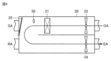
- FIG. 4 is a schematic diagram showing the state of the outdoor air processing unit 20 when the refrigerant leaks in the first embodiment.
- the arrows in FIG. 4 indicate the flow of air.
- the control device 60 sets the damper 25 to the refrigerant discharge position, which is the second position.
- the refrigerant discharge position (second position) is a position where the opening on the indoor side of the first air passage is blocked and a hole is opened in the boundary wall between the first air passage and the second air passage.
- the damper 25 is in the second position, as shown in FIG. 4, the outdoor air OA flows from the first air passage to the second air passage after passing through the indoor heat exchanger 21 by the first fan 23, and is discharged to the outside as exhaust air EA by the second fan 24 together with the leaked refrigerant.
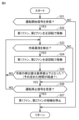
- FIG. 5 is a flowchart showing the control of the outside air processing unit 20 in embodiment 1.
- the processing of the flowchart in FIG. 5 is repeatedly called and executed as a subroutine from the main routine in the control of the control device 60.
- step S11 the control device 60 determines whether or not an operation start signal has been received.
- the operation start signal is a signal transmitted from an input device such as a remote control in response to a user's operation. If the control device 60 has not received an operation start signal (NO in S11), the control device 60 returns the process from the subroutine to the main routine. If the control device 60 has received an operation start signal in S11 (YES in S11), the control device 60 sets the damper 25 to the indoor air outlet position shown in FIG. 3 (S12).
- the control device 60 operates the first fan 23 and the second fan 24 (S13).
- the outdoor air processing unit 20 the outdoor air OA is passed through the indoor heat exchanger 21 by the first fan 23, and then flows through the first air duct so as to be supplied to the room as supply air SA.
- the indoor air RA flows through the second air duct so as to be exhausted to the outside of the room as exhaust air EA by the second fan 24.
- control device 60 determines whether or not a refrigerant leak has been detected based on the information transmitted from the sensor 50 (S14). If the control device 60 has not detected a refrigerant leak (NO in S14), it proceeds to processing in S17. If the control device 60 detects a refrigerant leak (YES in S14), it sets the damper 25 to the refrigerant discharge position shown in FIG. 4 in S15 (S15).
- the control device 60 determines whether the detection value of the refrigerant sent from the sensor 50 is equal to or less than a predetermined reference value (S16). If the detection value of the refrigerant is greater than the reference value (NO in S16), the control device 60 proceeds to processing of S14. If the detection value of the refrigerant is equal to or less than the reference value (YES in S16), the control device 60 proceeds to processing of S17. Note that the control device 60 may also determine whether a predetermined time has elapsed since the sensor 50 detected a refrigerant leak in processing of S16. This allows the condition that the refrigerant has been discharged to be that the predetermined time has elapsed.
- the control device 60 determines whether or not an operation stop signal has been received in S17.
- the operation stop signal is a signal transmitted from an input device such as a remote control in response to a user operation. If the control device 60 has not received an operation stop signal (NO in S17), it proceeds to processing in S14. If the control device 60 has received an operation stop signal in S17 (YES in S17), it stops the operation of the first fan 23 and the second fan 24 (S18) and returns processing from the subroutine to the main routine.
- the first fan 23 and the second fan 24 supply outdoor air OA to the room as supply air SA, and exhaust indoor air RA to the outside as exhaust air EA, by the process of S13 in FIG. 5.
- the control device 60 sets the damper 25 to the refrigerant exhaust position by the process of S15.
- the outdoor air OA flows from the first air duct in which the indoor heat exchanger 21 is installed to the second air duct, and is exhausted to the outside together with the leaked refrigerant as exhaust air EA.
- the outdoor air processing unit 20 can effectively exhaust the refrigerant to the outside without reducing the exhaust air volume because the outdoor air OA is always taken in by the outdoor air processing unit 20.
- the control device 60 determines whether the detected refrigerant value is below the reference value, and if so, determines whether to stop the operation of the first fan 23 and the second fan 24. This ensures that the leaked refrigerant is discharged outside.
- Embodiment 2 The outdoor air processing unit 20A of the second embodiment will be described.
- the outdoor air processing unit 20A of the second embodiment does not have a damper 25, and the control of the first fan 23 and the second fan 24 is different from that of the outdoor air processing unit 20 of the first embodiment.
- the rest of the configuration is the same as that of the outdoor air processing unit 20 of the first embodiment.
- Figure 6 is a schematic diagram showing the state of the outdoor air processing unit 20A during normal operation in embodiment 2.
- the arrows in Figure 6 indicate the flow of air.
- the control device 60 rotates the first fan 23 and the second fan 24 in the forward direction during normal operation.
- the outdoor air OA passes through the indoor heat exchanger 21 by the first fan 23, and then flows through the first air duct to be supplied to the room as supply air SA.
- the indoor air RA flows through the second air duct to be exhausted to the outside of the room as exhaust air EA by the second fan 24.
- FIG. 7 is a schematic diagram showing the state of the outdoor air processing unit 20A when the refrigerant leaks in the second embodiment.
- the arrows in FIG. 7 indicate the flow of air.
- the control device 60 rotates the first fan 23 and the second fan 24 in the opposite direction to that during normal operation.
- the indoor air RA flows through the first air duct so as to be exhausted to the outside of the room as exhaust air EA after passing through the indoor heat exchanger 21 by the first fan 23.
- FIG. 7 is a schematic diagram showing the state of the outdoor air processing unit 20A when the refrigerant leaks in the second embodiment.
- the arrows in FIG. 7 indicate the flow of air.
- the outdoor air OA flows through the second air duct so as to be supplied to the room as supply air SA by the second fan 24.
- the direction of the air flowing through the first air duct and the second air duct is opposite to that during normal operation.
- FIG. 8 is a flowchart showing the control of the outside air processing unit 20A in embodiment 2.
- the processing of the flowchart in FIG. 8 is repeatedly called and executed as a subroutine from the main routine in the control of the control device 60.
- step S21 the control device 60 determines whether or not an operation start signal has been received.
- the operation start signal is a signal transmitted from an input device such as a remote control in response to a user's operation. If the control device 60 has not received an operation start signal (NO in S21), the control device 60 returns the process from the subroutine to the main routine. If the control device 60 has received an operation start signal in S21 (YES in S21), the control device 60 operates the first fan 23 and the second fan 24 in the forward rotation direction as shown in FIG. 6 (S22).
- control device 60 determines whether or not a refrigerant leak has been detected based on the information transmitted from the sensor 50 (S23). If the control device 60 has not detected a refrigerant leak (NO in S23), it proceeds to processing in S26. If the control device 60 has detected a refrigerant leak (YES in S23), it operates the first fan 23 and the second fan 24 in the opposite direction to normal operation (S24), as shown in FIG. 7.
- the control device 60 determines whether the detection value of the refrigerant sent from the sensor 50 is equal to or less than a predetermined reference value (S25). If the detection value of the refrigerant is greater than the reference value (NO in S25), the control device 60 proceeds to processing of S23. If the detection value of the refrigerant is equal to or less than the reference value (YES in S25), the control device 60 proceeds to processing of S26. Note that the control device 60 may also determine whether a predetermined time has elapsed since the sensor 50 detected a refrigerant leak in processing of S25. This allows the condition that the refrigerant has been discharged to be that the predetermined time has elapsed.
- the control device 60 determines whether or not an operation stop signal has been received in S26.
- the operation stop signal is a signal transmitted from an input device such as a remote control in response to a user operation. If the control device 60 has not received an operation stop signal (NO in S26), it proceeds to processing in S23. If the control device 60 has received an operation stop signal in S26 (YES in S26), it stops the operation of the first fan 23 and the second fan 24 (S27) and returns processing from the subroutine to the main routine.
- the first fan 23 and the second fan 24 are rotated in the forward direction by the process of S22 in FIG. 8, so that outdoor air OA is supplied to the room as supply air SA and indoor air RA is exhausted to the outside as exhaust air EA.
- the control device 60 rotates the first fan 23 and the second fan 24 in the reverse direction to that during normal operation by the process of S24.
- the indoor air RA flows through the first air duct to be exhausted to the outside as exhaust air EA after passing through the indoor heat exchanger 21 together with the leaked refrigerant.
- the outdoor air OA flows through the second air duct to be supplied to the room as supply air SA by the second fan 24.
- the outdoor air processing unit 20A is able to blow air containing the refrigerant outside instead of into the room.
- the outdoor air processing unit 20A can constantly take in clean air into the room via the outdoor air processing unit 20, which can prevent the deterioration of indoor air quality. Because the outdoor air OA is constantly taken in by the outdoor air processing unit 20, the outdoor air processing unit 20A and the room do not become negative pressure, and the refrigerant can be effectively discharged outside without reducing the exhaust air volume.
- control device 60 determines whether the detected refrigerant value is below the reference value, and if so, determines whether to stop the operation of the first fan 23 and the second fan 24. This ensures that the leaked refrigerant is discharged outside.
- the air conditioner 100 of the present disclosure includes an outdoor unit 10, outdoor air processing units 20, 20A as indoor units, a refrigerant pipe 30 that connects the outdoor unit 10 and the outdoor air processing unit 20 and through which a refrigerant flows, an expansion valve 22 that reduces the pressure of the refrigerant, and a control device 60.
- the outdoor unit 10 includes a compressor 11 and an outdoor heat exchanger 13.
- the outdoor air processing units 20, 20A include a first fan 23 installed in a first air duct, a second fan 24 installed in a second air duct, an indoor heat exchanger 21 installed in the first air duct, and a sensor 50 that detects refrigerant leakage in the first air duct.
- a refrigerant circuit 110 is configured in which a refrigerant flows in the order of the compressor 11, the outdoor heat exchanger 13, the expansion valve 22, the indoor heat exchanger 21, and the compressor 11 during cooling operation.
- the control device 60 operates one of the first fan 23 and the second fan 24 to supply air from outside the room, and operates the other to exhaust air to the outside, thereby discharging air from the first air duct in which the indoor heat exchanger 21 is installed.
- control device 60 stops the operation of the first fan 23 and the second fan 24 after the sensor 50 detects a refrigerant leak and the detection value of the sensor 50 falls below a predetermined reference value.
- control device 60 stops the operation of the first fan 23 and the second fan 24 after a predetermined time has elapsed since the sensor 50 detected a refrigerant leak.
- the outdoor air processing unit 20 further includes a damper 25 that is set to an indoor blowing position during normal operation and set to a refrigerant discharge position when the sensor 50 detects a refrigerant leak.
- the indoor blowing position is a position where the outdoor air OA is taken into the room after passing through the first air duct
- the refrigerant discharge position is a position where the outdoor air OA is discharged to the outside after passing through the second air duct after passing through the first air duct.
- the control device 60 rotates the first fan 23 in the forward direction to take in outdoor air OA through the first air duct and rotates the second fan 24 in the forward direction to expel indoor air RA to the outside through the second air duct, and when the sensor 50 detects a refrigerant leak, it rotates the first fan 23 in the reverse direction to expel the leaked refrigerant to the outside through the first air duct and rotates the second fan 24 in the reverse direction to take in outdoor air OA through the second air duct.
- the present disclosure relates to an outdoor air processing unit 20, 20A connected to an outdoor unit 10.
- the outdoor air processing unit 20, 20A includes a first fan 23 installed in a first air duct, a second fan 24 installed in a second air duct, an indoor heat exchanger 21 installed in the first air duct and through which a refrigerant circulates between the outdoor unit 10 and the outdoor air processing unit 20, 20A, and a sensor 50 that detects refrigerant leakage in the first air duct.
- the sensor 50 detects a refrigerant leakage
- one of the first fan 23 and the second fan 24 operates to supply air from the outdoors and the other operates to exhaust air to the outdoors, discharging air in the first air duct in which the indoor heat exchanger 21 is installed.
- the outdoor air processing units 20, 20A of this embodiment and the air conditioner 100 equipped with the outdoor air processing units 20, 20A are configured as described above, so that even if the refrigerant leaks, the outdoor air OA is always taken into the outdoor air processing units 20, 20A, and the refrigerant can be effectively discharged without reducing the exhaust air volume when the refrigerant leaks.
- the outdoor air processing unit 20A can always take in clean air into the room through the outdoor air processing unit 20, which prevents the deterioration of the indoor air quality and prevents the room from becoming negative pressure.
Landscapes
- Engineering & Computer Science (AREA)
- Chemical & Material Sciences (AREA)
- Combustion & Propulsion (AREA)
- Mechanical Engineering (AREA)
- General Engineering & Computer Science (AREA)
- Air Conditioning Control Device (AREA)
Abstract
空気調和機(100)は、室外機(10)と、外気処理ユニット(20)と、冷媒配管(30)と、膨張弁(22)と、制御装置(60)とを備える。室外機(10)は、圧縮機(11)と、室外熱交換器(13)とを備える。外気処理ユニット(20)は、第1ファン(23)と、第2ファン(24)と、室内熱交換器(21)と、センサ(50)とを備える。冷房運転中に圧縮機(11)、室外熱交換器(14)、膨張弁(22)、室内熱交換器(21)、圧縮機(11)の順に冷媒が流れる冷媒回路(110)が構成される。制御装置(60)は、センサ(50)が冷媒の漏洩を検出した際に、第1ファン(23)および第2ファン(24)のうち一方を室外からの給気用として動作させ、他方を室外への排気用として動作させ、室内熱交換器(21)が設置されている第1風路内の空気を排出する。
Description
本開示は、外気処理ユニットおよび外気処理ユニットを備えた空気調和機に関する。
空気調和機の方式の一つとして、室外から吸い込んだ空気を熱交換器により温度調整し室内に取り入れるとともに、室内空気を室外へ吐き出す外気処理ユニットがある。このような外気処理ユニットにおいて可燃性もしくは微燃性の冷媒が使用されることがある。外気処理ユニットにおいて可燃性もしくは微燃性の冷媒が漏洩した場合、冷媒の濃度を下げるために冷媒を含む空気を外気処理ユニットの外部へ排出することが望ましい。
特開2017-75777号公報(特許文献1)には、外気処理ユニットとしての利用側空調装置および利用側空調装置を備えた空調装置において、漏洩した冷媒を排出する技術が開示されている。特開2017-75777号公報(特許文献1)では、冷媒漏洩検知装置が冷媒の漏洩を検知した際に、給排気機構によってケーシング内の空気とともに冷媒を排出する。
しかしながら、例えば気密性の高い物件において特開2017-75777号公報(特許文献1)の技術を適用する場合、室内が負圧となり室外へ排出する排気風量が低下することが懸念される。
本開示の目的は、冷媒の漏洩時に排気風量を低下させず効果的に冷媒を排出することのできる外気処理ユニットおよび外気処理ユニットを備えた空気調和機を提供することである。
本開示の空気調和機は、室外機と、室内機と、室外機と室内機とを接続し内部に冷媒が流れる配管と、冷媒を減圧する膨張弁と、制御装置とを備える。室外機は、圧縮機と、第1熱交換器とを備える。室内機は、第1風路に設置される第1ファンと、第2風路に設置される第2ファンと、第1風路に設置される第2熱交換器と、第1風路において冷媒の漏洩を検出するセンサとを備える。冷房運転中に圧縮機、第1熱交換器、膨張弁、第2熱交換器、圧縮機の順に冷媒が流れる冷媒回路が構成される。制御装置は、センサが冷媒の漏洩を検出した際に、第1ファンおよび第2ファンのうち一方を室外からの給気用として動作させ、他方を室外への排気用として動作させ、第2熱交換器が設置されている第1風路内の空気を排出する。
本開示は、室外機と接続される外気処理ユニットに関する。外気処理ユニットは、第1風路に設置される第1ファンと、第2風路に設置される第2ファンと、第1風路に設置され室外機との間で冷媒が循環する第2熱交換器と、第1風路において冷媒の漏洩を検出するセンサとを備える。第1ファンおよび第2ファンは、センサが冷媒の漏洩を検出した際に、一方が室外からの給気用として動作し、他方が室外への排気用として動作し、第2熱交換器が設置されている第1風路内の空気を排出する。
本開示の外気処理ユニットおよび空気調和機によれば、冷媒が漏洩した際に排気を実行するとともに給気が実行されるため、排気風量の低下を抑制し効果的に冷媒を排出することができる。
以下、本開示の実施の形態について、図面を参照しながら詳細に説明する。以下に説明する実施の形態において、個数、量などに言及する場合、特に記載がある場合を除き、本開示の範囲は必ずしもその個数、量などに限定されない。同一の部品、相当部品に対しては、同一の参照番号を付し、重複する説明は繰り返さない場合がある。実施の形態における構成を適宜組み合わせて用いることは当初から予定されている。
実施の形態1.
図1は、実施の形態1における空気調和機100の構成を示す概略図である。空気調和機100は、室外機10と、室内機として機能する外気処理ユニット20と、冷媒配管30とを備える。図1では、外気処理ユニット20を側面から見た概略図が示されている。室外機10と外気処理ユニット20とは、冷媒配管30により接続されている。外気処理ユニット20は、本体ケーシング内に、室内熱交換器21と、第1ファン23と、第2ファン24と、ダンパ25と、センサ50とを備える。
図1は、実施の形態1における空気調和機100の構成を示す概略図である。空気調和機100は、室外機10と、室内機として機能する外気処理ユニット20と、冷媒配管30とを備える。図1では、外気処理ユニット20を側面から見た概略図が示されている。室外機10と外気処理ユニット20とは、冷媒配管30により接続されている。外気処理ユニット20は、本体ケーシング内に、室内熱交換器21と、第1ファン23と、第2ファン24と、ダンパ25と、センサ50とを備える。
外気処理ユニット20は、天井裏101に配置されている。外気処理ユニット20は、室外空気OAをダクト40へ取込み、吹出口41から給気SAとして吹き出す。外気処理ユニット20は、室内空気RAを吸込口42を介してダクト40へ取込み、排気EAとして室外へ吐き出す。
室内熱交換器21は、冷媒と空気との間で熱交換を行なう室内熱交換器である。室外空気OAは、第1ファン23によって室内熱交換器21を通過した後に、給気SAとして室内に供給される。室内熱交換器21および第1ファン23が設置されている風路を第1風路と称する。他方、室内空気RAは、第2ファン24によって排気EAとして室外に排出される。第2ファン24が設置されている風路を第2風路と称する。
ダンパ25は、第1位置と第2位置とに位置を切替えることによって空気の流れを切替える。第1位置は、空気が室内に吹き出す室内吹出位置である。第2位置は、漏洩した冷媒を室外へ排出する冷媒排出位置である。センサ50は、冷媒の漏洩を検出するためのセンサである。センサ50は、室内熱交換器21の近傍に配置されている。
図2は、実施の形態1における空気調和機100の冷媒回路110を示す図である。図2に示すように、空気調和機100は、室外機10と、室内機として機能する外気処理ユニット20とを備える。室外機10と外気処理ユニット20とは、冷媒配管30により接続され、冷媒回路110を構成する。室外機10は、圧縮機11と、四方弁12と、室外熱交換器13と、室外ファン14とを備える。外気処理ユニット20は、室内熱交換器21と、膨張弁22とを備える。なお、膨張弁22は、外気処理ユニット20に設置される例を説明するが、室外機10側に設置されてもよい。
冷媒回路110は、冷房運転中において、圧縮機11、室外熱交換器13、膨張弁22、および室内熱交換器21の順に冷媒が循環するように構成される。冷房運転中は、室外熱交換器13が凝縮器として機能し、室内熱交換器21が蒸発器として機能する。空気調和機100は、暖房運転中において、四方弁12が切替えられることによって冷房運転中と逆方向に冷媒が流れる。
圧縮機11は、低温、低圧の冷媒を吸入して圧縮し、高温、高圧のガス冷媒として吐出する。圧縮機11は、例えば、インバータにより駆動し、容量(単位時間当たりに吐出する冷媒の量)が制御される。四方弁12は、空気調和機100の運転モードに応じて冷媒の流れを切替える。
室外熱交換器13は、冷媒回路110を流れる冷媒と室外空気との間で熱交換を行なう。室外熱交換器13には、室外ファン14が隣接されている。室外ファン14は、室外熱交換器13への送風を行なう。膨張弁22は、例えば、弁の開度が制御可能な電子式膨張弁で構成される。室内熱交換器21は、図1に示す第1ファン23によって送風される室外空気と冷媒回路110を流れる冷媒との間で熱交換を行なう。空気調和機100は、室外ファン14、第1ファン23、第2ファン24、ダンパ25、膨張弁22等の駆動部品を統括的に制御する制御装置60を備えている。
制御装置60は、CPU(Central Processing Unit)61と、メモリ62(ROM(Read Only Memory)およびRAM(Random Access Memory))と、各種信号を入出力するための図示しない入出力装置等を含んで構成される。CPU61は、ROMに格納されているプログラムをRAM等に展開して実行する。ROMに格納されるプログラムは、制御装置60の処理手順が記されたプログラムである。制御装置60は、これらのプログラムに従って、各機器の制御を実行する。この制御については、ソフトウェアによる処理に限られず、専用のハードウェア(電子回路)で処理することも可能である。
制御装置60は、例えば、室外ファン14、第1ファン23、第2ファン24の回転速度を制御することによって、送風量を調整する。制御装置60は、例えば、膨張弁22の開度を制御することによって、冷媒の減圧量を制御する。制御装置60は、例えば、ダンパ25を制御することによって、ダンパ25の位置を切り替える。なお、制御装置60は、室外機10および外気処理ユニット20においてそれぞれ設けられ、互いに通信可能に設置されるようにしてもよい。
次に、通常運転中における外気処理ユニット20の状態について説明する。図3は、実施の形態1における通常運転中の外気処理ユニット20の状態を示す概略図である。図3の矢印は、空気の流れを示している。制御装置60は、通常運転中においてダンパ25を第1位置である室内吹出位置とする。室内吹出位置(第1位置)は、第1風路と第2風路との境界壁に設けられた穴を塞ぐ位置である。ダンパ25が第1位置となることによって、図3に示すように、室外空気OAは第1ファン23によって室内熱交換器21を通過した後に、給気SAとして室内に供給されるように第1風路を流れる。他方、図3に示すように、室内空気RAは、第2ファン24によって排気EAとして室外に排気されるように第2風路を流れる。
次に、冷媒が漏洩した際の外気処理ユニット20の状態について説明する。図4は、実施の形態1における冷媒が漏洩した際の外気処理ユニット20の状態を示す概略図である。図4の矢印は、空気の流れを示している。制御装置60は、センサ50により冷媒の漏洩が検知された場合、ダンパ25を第2位置である冷媒排出位置とする。冷媒排出位置(第2位置)は、第1風路の室内側の口を塞ぎ、第1風路と第2風路との境界壁の穴を開く位置である。ダンパ25が第2位置となることによって、図4に示すように、室外空気OAは第1ファン23によって室内熱交換器21を通過した後に、第1風路から第2風路へ流れ、漏洩した冷媒とともに第2ファン24によって排気EAとして室外に排出される。
次に、制御装置60が実行する処理について説明する。図5は、実施の形態1における外気処理ユニット20の制御を示すフローチャートである。図5のフローチャートの処理は、制御装置60の制御におけるメインルーチンから、サブルーチンとして繰返し呼び出されて実行される。
制御装置60は、ステップS11において、運転開始信号を受信したか否かを判定する。運転開始信号は、ユーザの操作によりリモコン等の入力装置から送信される信号である。制御装置60は、運転開始信号を受信していない場合(S11のNO)、処理をサブルーチンからメインルーチンに戻す。制御装置60は、S11において運転開始信号を受信した場合(S11のYES)、ダンパ25を図3に示す室内吹出位置とする(S12)。
次いで、制御装置60は、第1ファン23、および第2ファン24を稼働させる(S13)。これによって、外気処理ユニット20では室外空気OAが、第1ファン23によって室内熱交換器21を通過した後に、給気SAとして室内に供給されるように第1風路を流れる。他方、室内空気RAが、第2ファン24によって排気EAとして室外に排気されるように第2風路を流れる。
次いで、制御装置60は、センサ50から送信される情報によって冷媒漏洩を検出したか否かを判定する(S14)。制御装置60は、冷媒漏洩を検出していない場合(S14のNO)、S17の処理へ移行する。制御装置60は、冷媒漏洩を検出した場合(S14のYES)、S15においてダンパ25を図4に示す冷媒排出位置とする(S15)。
次いで、制御装置60は、センサ50から送信される冷媒の検出値が予め定められた基準値以下となったか否かを判定する(S16)。制御装置60は、冷媒の検出値が基準値よりも大きい場合(S16のNO)、S14の処理へ移行する。制御装置60は、冷媒の検出値が基準値以下となっている場合(S16のYES)、S17の処理へ移行する。なお、制御装置60は、S16の処理においてセンサ50が冷媒の漏洩を検出してから予め定められた時間が経過したか否かの判定をしてもよい。これによって、予め定められた時間が経過したことを冷媒が排出された条件とすることができる。
制御装置60は、S17において運転停止信号を受信したか否かを判定する。運転停止信号は、ユーザの操作によりリモコン等の入力装置から送信される信号である。制御装置60は、運転停止信号を受信していない場合(S17のNO)、S14の処理へ移行する。制御装置60は、S17において運転停止信号を受信した場合(S17のYES)、第1ファン23、および第2ファン24の稼働を停止し(S18)、処理をサブルーチンからメインルーチンに戻す。
図5のS13の処理によって、通常運転中は、第1ファン23および第2ファン24によって、室外空気OAを給気SAとして室内に供給し、室内空気RAを排気EAとして室外に排出する。センサ50が冷媒の漏洩を検出した際は、S15の処理によって制御装置60がダンパ25を冷媒排出位置とする。これによって、室外空気OAが室内熱交換器21の設置されている第1風路から第2風路へ流れ、漏洩した冷媒とともに排気EAとして室外に排出される。外気処理ユニット20は、冷媒が漏洩した場合であっても室外空気OAが外気処理ユニット20内に常に取り込まれているため排気風量を低下させずに効果的に冷媒を室外へ排出することができる。
図5のS16の処理によって、制御装置60は、冷媒の検出値が基準値以下となっているか否かを判定し、基準値以下となった場合に以降の第1ファン23、および第2ファン24を運転を停止する処理の判定をする。これによって、漏洩した冷媒を確実に室外へ排出することができる。
実施の形態2.
実施の形態2の外気処理ユニット20Aについて説明する。実施の形態2の外気処理ユニット20Aは、ダンパ25が設置されておらず、第1ファン23および第2ファン24の制御が実施の形態1の外気処理ユニット20と異なっている。それ以外の構成は、実施の形態1の外気処理ユニット20の構成と同様である。
実施の形態2の外気処理ユニット20Aについて説明する。実施の形態2の外気処理ユニット20Aは、ダンパ25が設置されておらず、第1ファン23および第2ファン24の制御が実施の形態1の外気処理ユニット20と異なっている。それ以外の構成は、実施の形態1の外気処理ユニット20の構成と同様である。
通常運転中における外気処理ユニット20Aの状態について説明する。図6は、実施の形態2における通常運転中の外気処理ユニット20Aの状態を示す概略図である。図6の矢印は、空気の流れを示している。制御装置60は、通常運転中において第1ファン23および第2ファン24を正回転させる。これによって、図6に示すように、室外空気OAは第1ファン23によって室内熱交換器21を通過した後に、給気SAとして室内に供給されるように第1風路を流れる。他方、図6に示すように、室内空気RAは、第2ファン24によって排気EAとして室外に排気されるように第2風路を流れる。
次に、冷媒が漏洩した際の外気処理ユニット20Aの状態について説明する。図7は、実施の形態2における冷媒が漏洩した際の外気処理ユニット20Aの状態を示す概略図である。図7の矢印は、空気の流れを示している。制御装置60は、センサ50により冷媒の漏洩が検知された場合、第1ファン23および第2ファン24を通常運転中と逆回転させる。これによって、図7に示すように、室内空気RAは、第1ファン23によって室内熱交換器21を通過した後に、排気EAとして室外に排気されるように第1風路を流れる。他方、図7に示すように、室外空気OAは第2ファン24によって給気SAとして室内に供給されるように第2風路を流れる。つまり、冷媒が漏洩した際は、第1風路および第2風路を流れる空気の向きが通常運転中とは逆向きとなる。
次に、制御装置60が実行する処理について説明する。図8は、実施の形態2における外気処理ユニット20Aの制御を示すフローチャートである。図8のフローチャートの処理は、制御装置60の制御におけるメインルーチンから、サブルーチンとして繰返し呼び出されて実行される。
制御装置60は、ステップS21において、運転開始信号を受信したか否かを判定する。運転開始信号は、ユーザの操作によりリモコン等の入力装置から送信される信号である。制御装置60は、運転開始信号を受信していない場合(S21のNO)、処理をサブルーチンからメインルーチンに戻す。制御装置60は、S21において運転開始信号を受信した場合(S21のYES)、第1ファン23および第2ファン24を図6に示すように正回転で稼働する(S22)。
次いで、制御装置60は、センサ50から送信される情報によって冷媒漏洩を検出したか否かを判定する(S23)。制御装置60は、冷媒漏洩を検出していない場合(S23のNO)、S26の処理へ移行する。制御装置60は、冷媒漏洩を検出した場合(S23のYES)、図7に示すように、第1ファン23および第2ファン24を通常運転中と逆回転で稼働する(S24)。
次いで、制御装置60は、センサ50から送信される冷媒の検出値が予め定められた基準値以下となったか否かを判定する(S25)。制御装置60は、冷媒の検出値が基準値よりも大きい場合(S25のNO)、S23の処理へ移行する。制御装置60は、冷媒の検出値が基準値以下となっている場合(S25のYES)、S26の処理へ移行する。なお、制御装置60は、S25の処理においてセンサ50が冷媒の漏洩を検出してから予め定められた時間が経過したか否かの判定をしてもよい。これによって、予め定められた時間が経過したことを冷媒が排出された条件とすることができる。
制御装置60は、S26において運転停止信号を受信したか否かを判定する。運転停止信号は、ユーザの操作によりリモコン等の入力装置から送信される信号である。制御装置60は、運転停止信号を受信していない場合(S26のNO)、S23の処理へ移行する。制御装置60は、S26において運転停止信号を受信した場合(S26のYES)、第1ファン23、および第2ファン24の稼働を停止し(S27)、処理をサブルーチンからメインルーチンに戻す。
図8のS22の処理によって、通常運転中は、第1ファン23および第2ファン24を正回転させることによって、室外空気OAを給気SAとして室内に供給し、室内空気RAを排気EAとして室外に排出する。センサ50が冷媒の漏洩を検出した際は、S24の処理によって制御装置60が第1ファン23および第2ファン24を通常運転中と逆回転させる。これによって、室内空気RAは、漏洩した冷媒とともに室内熱交換器21を通過した後に、排気EAとして室外に排気されるように第1風路を流れる。他方、室外空気OAは第2ファン24によって給気SAとして室内に供給されるように第2風路を流れる。
このように、外気処理ユニット20Aは、冷媒が漏洩した場合であっても冷媒を含む空気を室内へ吹き出さずに、室外へ吹き出すことが可能となる。外気処理ユニット20Aは、きれいな空気を常に外気処理ユニット20内を介して室内へ取り込むことができるため、室内空気の質の悪化を抑制することができる。外気処理ユニット20Aは、室外空気OAが外気処理ユニット20内に常に取り込まれているため外気処理ユニット20Aおよび室内が負圧となることがなく、排気風量を低下させずに効果的に冷媒を室外へ排出することができる。
図8のS25の処理によって、制御装置60は、冷媒の検出値が基準値以下となっているか否かを判定し、基準値以下となった場合に以降の第1ファン23、および第2ファン24を運転を停止する処理の判定をする。これによって、漏洩した冷媒を確実に室外へ排出することができる。
<まとめ>
本開示の空気調和機100は、室外機10と、室内機としての外気処理ユニット20,20Aと、室外機10と外気処理ユニット20とを接続し内部に冷媒が流れる冷媒配管30と、冷媒を減圧する膨張弁22と、制御装置60とを備える。室外機10は、圧縮機11と、室外熱交換器13とを備える。外気処理ユニット20,20Aは、第1風路に設置される第1ファン23と、第2風路に設置される第2ファン24と、第1風路に設置される室内熱交換器21と、第1風路において冷媒の漏洩を検出するセンサ50とを備える。冷房運転中に圧縮機11、室外熱交換器13、膨張弁22、室内熱交換器21、圧縮機11の順に冷媒が流れる冷媒回路110が構成される。制御装置60は、センサ50が冷媒の漏洩を検出した際に、第1ファン23および第2ファン24のうち一方を室外からの給気用として動作させ、他方を室外への排気用として動作させ、室内熱交換器21が設置されている第1風路内の空気を排出する。
本開示の空気調和機100は、室外機10と、室内機としての外気処理ユニット20,20Aと、室外機10と外気処理ユニット20とを接続し内部に冷媒が流れる冷媒配管30と、冷媒を減圧する膨張弁22と、制御装置60とを備える。室外機10は、圧縮機11と、室外熱交換器13とを備える。外気処理ユニット20,20Aは、第1風路に設置される第1ファン23と、第2風路に設置される第2ファン24と、第1風路に設置される室内熱交換器21と、第1風路において冷媒の漏洩を検出するセンサ50とを備える。冷房運転中に圧縮機11、室外熱交換器13、膨張弁22、室内熱交換器21、圧縮機11の順に冷媒が流れる冷媒回路110が構成される。制御装置60は、センサ50が冷媒の漏洩を検出した際に、第1ファン23および第2ファン24のうち一方を室外からの給気用として動作させ、他方を室外への排気用として動作させ、室内熱交換器21が設置されている第1風路内の空気を排出する。
好ましくは、制御装置60は、センサ50が冷媒の漏洩を検出してからセンサ50の検出値が予め定めた基準値以下となった後に第1ファン23および第2ファン24の動作を停止する。
好ましくは、制御装置60は、センサ50が冷媒の漏洩を検出してから予め定めた時間が経過した後に第1ファン23および第2ファン24の動作を停止する。
好ましくは、外気処理ユニット20は、通常運転中に室内吹出位置とされ、センサ50が冷媒の漏洩を検出した際に冷媒排出位置とされるダンパ25をさらに備える。室内吹出位置は、室外空気OAが第1風路を通過した後に室内に取り入れられる位置であり、冷媒排出位置は、室外空気OAが第1風路を通過した後に第2風路を通過し室外へ吐き出される位置である。
好ましくは、制御装置60は、通常運転中に第1ファン23を正回転させ第1風路を通して室外空気OAを室内に取り入れるとともに、第2ファン24を正回転させ第2風路を通して室内空気RAを室外へ吐き出し、センサ50が冷媒の漏洩を検出した際に第1ファン23を逆回転させ第1風路を通して漏洩した冷媒を室外へ吐き出すとともに、第2ファン24を逆回転させ第2風路を通して室外空気OAを室内へ取り入れる。
本開示は、室外機10と接続される外気処理ユニット20,20Aに関する。外気処理ユニット20,20Aは、第1風路に設置される第1ファン23と、第2風路に設置される第2ファン24と、第1風路に設置され室外機10との間で冷媒が循環する室内熱交換器21と、第1風路において冷媒の漏洩を検出するセンサ50とを備える。第1ファン23および第2ファン24は、センサ50が冷媒の漏洩を検出した際に、一方が室外からの給気用として動作し、他方が室外への排気用として動作し、室内熱交換器21が設置されている第1風路内の空気を排出する。
本実施の形態の外気処理ユニット20,20Aおよび外気処理ユニット20,20Aを備えた空気調和機100は、上記の構成を備えることによって、冷媒が漏洩した場合であっても室外空気OAが外気処理ユニット20,20A内に常に取り込まれているため、冷媒の漏洩時に排気風量を低下させず効果的に冷媒を排出することができる。特に外気処理ユニット20Aは、きれいな空気を常に外気処理ユニット20内を介して室内へ取り込むことができるため、室内空気の質の悪化を抑制し、室内が負圧とならないようにすることができる。
今回開示された実施の形態は、すべての点で例示であって制限的なものではないと考えられるべきである。本開示の範囲は、上記した実施の形態の説明ではなくて請求の範囲によって示され、請求の範囲と均等の意味および範囲内でのすべての変更が含まれることが意図される。
10 室外機、11 圧縮機、12 四方弁、13 室外熱交換器、14 室外ファン、20,20A 外気処理ユニット、21 室内熱交換器、22 膨張弁、23 第1ファン、24 第2ファン、25 ダンパ、30 冷媒配管、40 ダクト、41 吹出口、42 吸込口、50 センサ、60 制御装置、61 CPU、62 メモリ、100 空気調和機、101 天井裏、110 冷媒回路、EA 排気、OA 室外空気、RA 室内空気、SA 給気。
Claims (6)
- 室外機と、
室内機と、
前記室外機と前記室内機とを接続し内部に冷媒が流れる配管と、
冷媒を減圧する膨張弁と、
制御装置とを備え、
前記室外機は、
圧縮機と、
第1熱交換器とを備え、
前記室内機は、
第1風路に設置される第1ファンと、
第2風路に設置される第2ファンと、
前記第1風路に設置される第2熱交換器と、
前記第1風路において冷媒の漏洩を検出するセンサとを備え、
冷房運転中に前記圧縮機、前記第1熱交換器、前記膨張弁、前記第2熱交換器、前記圧縮機の順に冷媒が流れる冷媒回路が構成され、
前記制御装置は、前記センサが冷媒の漏洩を検出した際に、前記第1ファンおよび前記第2ファンのうち一方を室外からの給気用として動作させ、他方を室外への排気用として動作させ、前記第2熱交換器が設置されている前記第1風路内の空気を排出する、空気調和機。 - 前記制御装置は、前記センサが冷媒の漏洩を検出してから前記センサの検出値が予め定めた基準値以下となった後に前記第1ファンおよび前記第2ファンの動作を停止する、請求項1に記載の空気調和機。
- 前記制御装置は、前記センサが冷媒の漏洩を検出してから予め定めた時間が経過した後に前記第1ファンおよび前記第2ファンの動作を停止する、請求項1に記載の空気調和機。
- 前記室内機は、通常運転中に第1位置とされ、前記センサが冷媒の漏洩を検出した際に第2位置とされるダンパをさらに備え、
前記第1位置は、室外空気が前記第1風路を通過した後に室内に取り入れられる位置であり、前記第2位置は、室外空気が前記第1風路を通過した後に前記第2風路を通過し室外へ吐き出される位置である、請求項1から請求項3のいずれか1項に記載の空気調和機。 - 前記制御装置は、
通常運転中に前記第1ファンを正回転させ前記第1風路を通して室外空気を室内に取り入れるとともに、前記第2ファンを正回転させ前記第2風路を通して室内空気を室外へ吐き出し、
前記センサが冷媒の漏洩を検出した際に前記第1ファンを逆回転させ前記第1風路を通して漏洩した冷媒を室外へ吐き出すとともに、前記第2ファンを逆回転させ前記第2風路を通して室外空気を室内へ取り入れる、請求項1から請求項3のいずれか1項に記載の空気調和機。 - 室外機と接続される外気処理ユニットであって、
第1風路に設置される第1ファンと、
第2風路に設置される第2ファンと、
前記第1風路に設置され前記室外機との間で冷媒が循環する第2熱交換器と、
前記第1風路において冷媒の漏洩を検出するセンサとを備え、
前記第1ファンおよび前記第2ファンは、前記センサが冷媒の漏洩を検出した際に、一方が室外からの給気用として動作し、他方が室外への排気用として動作し、前記第2熱交換器が設置されている前記第1風路内の空気を排出する、外気処理ユニット。
Priority Applications (1)
| Application Number | Priority Date | Filing Date | Title |
|---|---|---|---|
| PCT/JP2023/021553 WO2024252670A1 (ja) | 2023-06-09 | 2023-06-09 | 外気処理ユニットおよび空気調和機 |
Applications Claiming Priority (1)
| Application Number | Priority Date | Filing Date | Title |
|---|---|---|---|
| PCT/JP2023/021553 WO2024252670A1 (ja) | 2023-06-09 | 2023-06-09 | 外気処理ユニットおよび空気調和機 |
Publications (1)
| Publication Number | Publication Date |
|---|---|
| WO2024252670A1 true WO2024252670A1 (ja) | 2024-12-12 |
Family
ID=93795851
Family Applications (1)
| Application Number | Title | Priority Date | Filing Date |
|---|---|---|---|
| PCT/JP2023/021553 Ceased WO2024252670A1 (ja) | 2023-06-09 | 2023-06-09 | 外気処理ユニットおよび空気調和機 |
Country Status (1)
| Country | Link |
|---|---|
| WO (1) | WO2024252670A1 (ja) |
Citations (6)
| Publication number | Priority date | Publication date | Assignee | Title |
|---|---|---|---|---|
| WO2017187483A1 (ja) * | 2016-04-25 | 2017-11-02 | 三菱電機株式会社 | 室内機および空気調和装置 |
| WO2019097604A1 (ja) * | 2017-11-15 | 2019-05-23 | 日立ジョンソンコントロールズ空調株式会社 | ダクト式空気調和機 |
| JP2019086246A (ja) * | 2017-11-08 | 2019-06-06 | 三菱電機株式会社 | 換気システム、空調システム、換気方法及びプログラム |
| WO2021192374A1 (ja) * | 2020-03-27 | 2021-09-30 | 三菱電機株式会社 | 車両用空気調和装置 |
| US20210310678A1 (en) * | 2017-12-01 | 2021-10-07 | Johnson Controls Tyco IP Holdings LLP | Systems and methods for refrigerant leak management |
| WO2023002653A1 (ja) * | 2021-07-23 | 2023-01-26 | 三菱電機株式会社 | 空気調和機 |
-
2023
- 2023-06-09 WO PCT/JP2023/021553 patent/WO2024252670A1/ja not_active Ceased
Patent Citations (6)
| Publication number | Priority date | Publication date | Assignee | Title |
|---|---|---|---|---|
| WO2017187483A1 (ja) * | 2016-04-25 | 2017-11-02 | 三菱電機株式会社 | 室内機および空気調和装置 |
| JP2019086246A (ja) * | 2017-11-08 | 2019-06-06 | 三菱電機株式会社 | 換気システム、空調システム、換気方法及びプログラム |
| WO2019097604A1 (ja) * | 2017-11-15 | 2019-05-23 | 日立ジョンソンコントロールズ空調株式会社 | ダクト式空気調和機 |
| US20210310678A1 (en) * | 2017-12-01 | 2021-10-07 | Johnson Controls Tyco IP Holdings LLP | Systems and methods for refrigerant leak management |
| WO2021192374A1 (ja) * | 2020-03-27 | 2021-09-30 | 三菱電機株式会社 | 車両用空気調和装置 |
| WO2023002653A1 (ja) * | 2021-07-23 | 2023-01-26 | 三菱電機株式会社 | 空気調和機 |
Similar Documents
| Publication | Publication Date | Title |
|---|---|---|
| US7997097B2 (en) | Air conditioner | |
| JP6225776B2 (ja) | マルチタイプ空気調和機 | |
| JP2002228281A (ja) | 空気調和機 | |
| US20050257539A1 (en) | Air conditioner and method for controlling operation thereof | |
| JP4797727B2 (ja) | 冷凍装置 | |
| JP2025057923A (ja) | 冷凍サイクル装置 | |
| US7624587B2 (en) | Multi-stage operation type air conditioner | |
| WO2024252670A1 (ja) | 外気処理ユニットおよび空気調和機 | |
| JPH07310962A (ja) | ヒートポンプ式マルチタイプ空気調和機 | |
| KR20040034906A (ko) | 멀티 공조기의 역상/결상 감지방법 | |
| JP2002243307A (ja) | 空気調和装置 | |
| JP7625145B2 (ja) | 空気調和装置および空気調和システム | |
| CN111322723A (zh) | 多联机空调系统及其控制方法、控制装置和存储介质 | |
| JP3123873B2 (ja) | 空気調和装置 | |
| JP2003329290A (ja) | 空気調和機の運転制御方法 | |
| US11988403B2 (en) | Air conditioner and control method thereof | |
| JP4830399B2 (ja) | 空気調和装置 | |
| JP7709065B2 (ja) | 冷凍サイクル装置 | |
| JP4778849B2 (ja) | 空気調和機 | |
| KR100502308B1 (ko) | 멀티 에어컨의 바이패스 장치 및 그 제어방법 | |
| JP7657096B2 (ja) | 冷凍サイクル装置および冷媒漏洩判定システム | |
| JP3748620B2 (ja) | 空気調和装置 | |
| KR102105655B1 (ko) | 공기 조화기 및 그 제어방법 | |
| JP2005037003A (ja) | 空気調和機 | |
| JP2002013777A (ja) | 空気調和装置 |
Legal Events
| Date | Code | Title | Description |
|---|---|---|---|
| 121 | Ep: the epo has been informed by wipo that ep was designated in this application |
Ref document number: 23940768 Country of ref document: EP Kind code of ref document: A1 |
|
| NENP | Non-entry into the national phase |
Ref country code: DE |