WO2024252651A1 - エラー要因識別装置 - Google Patents
エラー要因識別装置 Download PDFInfo
- Publication number
- WO2024252651A1 WO2024252651A1 PCT/JP2023/021457 JP2023021457W WO2024252651A1 WO 2024252651 A1 WO2024252651 A1 WO 2024252651A1 JP 2023021457 W JP2023021457 W JP 2023021457W WO 2024252651 A1 WO2024252651 A1 WO 2024252651A1
- Authority
- WO
- WIPO (PCT)
- Prior art keywords
- error
- unit
- cause
- mounting
- component
- Prior art date
- Legal status (The legal status is an assumption and is not a legal conclusion. Google has not performed a legal analysis and makes no representation as to the accuracy of the status listed.)
- Ceased
Links
Images





Classifications
-
- H—ELECTRICITY
- H05—ELECTRIC TECHNIQUES NOT OTHERWISE PROVIDED FOR
- H05K—PRINTED CIRCUITS; CASINGS OR CONSTRUCTIONAL DETAILS OF ELECTRIC APPARATUS; MANUFACTURE OF ASSEMBLAGES OF ELECTRICAL COMPONENTS
- H05K13/00—Apparatus or processes specially adapted for manufacturing or adjusting assemblages of electric components
- H05K13/08—Monitoring manufacture of assemblages
- H05K13/083—Quality monitoring using results from monitoring devices, e.g. feedback loops
Definitions
- This specification relates to an error cause identification device that identifies the cause of an error that occurs during the mounting operation of a component mounting machine.
- a typical example of a substrate-to-substrate operation machine is a component mounting machine that mounts components.
- a component mounting machine is equipped with a component supply unit such as a tape feeder that supplies components, and a component mounting unit such as a suction nozzle that picks up components from the component supply unit and mounts them on the substrate.
- a component supply unit such as a tape feeder that supplies components
- a component mounting unit such as a suction nozzle that picks up components from the component supply unit and mounts them on the substrate.
- the component mounting machine discards the component in question and performs the mounting operation again using a different component. For this reason, an increase in mounting operation errors leads to an increase in the component discard rate, which may even increase the defective rate of PCB products.
- Patent Document 1 discloses an example of a technique for identifying the cause of errors when there is an increase in mounting operation errors.
- Patent Document 1 discloses a mounting error cause estimation device that includes an error history storage unit that collects and stores error occurrence situations in which a mounting operation fails in a component mounting machine, a factor setting unit that sets a first cause and a second cause from among devices and data used in the mounting operation, a first determination unit that determines whether the error occurrence situation obtained for each individual of the second cause under conditions in which an individual of the first cause is specified is biased according to differences in the second cause, a second determination unit that determines whether the error occurrence situation obtained for each individual of the first cause under conditions in which an individual of the second cause is specified is biased according to differences in the first cause, and a cause estimation unit that estimates the individual causing the error (cause) based on the determination results of the first determination unit and the second determination unit.
- the cause estimation device is said to be able to estimate the individual causing the error with higher reliability than before based on a large number of determination results.
- the problem to be solved in this specification is to provide an error cause identification device that can reduce the number of cases in which the cause of an error is not identified when the number of mounting operation errors increases in a component mounting machine.
- an error cause identification device that includes a storage unit that stores operation quality information indicating the quality of each operation result of a mounting operation performed multiple times in a component mounting machine, and operation condition information indicating two or more of the multiple components of the component mounting machine and the mounting job data involved in each of the multiple mounting operations; an identification unit that, when the occurrence rate or occurrence frequency of an error in the mounting operation exceeds a predetermined value in at least one of the component mounting machine, the components, and the mounting job data, compares two or more of the error contribution rate for each component calculated based on the operation quality information and the operation condition information and the error contribution rate of the mounting job data to identify the component or the mounting job data that is the cause of the error; and an estimation unit that estimates the component or the mounting job data that is the cause of the error using a predetermined estimation logic that differs from the comparison of the error contribution rates.
- the memory unit stores operation pass/fail information and operating condition information for each mounting operation performed multiple times by the component mounting machine. Furthermore, the identification unit compares two or more error contribution rates to identify the cause of the error when the error occurrence rate or number of occurrences in the mounting operation exceeds a predetermined value, and the estimation unit estimates the cause of the error using estimation logic different from that of the identification unit.
- “identify” and “estimate” correspond to one form of “identify,” so that even in cases where the identification unit is unable to identify (specify) the cause of the error, the estimation unit can identify (estimate) the cause of the error, thereby reducing the number of cases in which the cause of the error is not identified.
- FIG. 1 is a diagram including a functional block diagram of an error cause identification device according to an embodiment and a plan view showing a schematic configuration example of a component mounting machine to which the device is applied; 11 is a diagram illustrating an example of log data of a component mounting machine including operation quality information and operating condition information.
- FIG. 4 is a diagram showing an example of a mounting cycle executed by a component mounting machine.
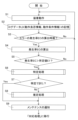
- FIG. 4 is an operational flow diagram illustrating the operation of the error cause identification device according to the embodiment.
- FIG. 13 is a table showing an example of the number of operations of a population when the occurrence rate of individual errors is calculated collectively for component supply units and component mounting units each time a component mounting machine performs mounting operations on a predetermined number of boards.
- FIG. 13 is a table showing the number of times an error occurred, the rate at which an error occurred, and the rate at which an error contributed in the first example.
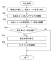
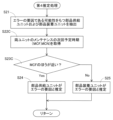
- FIG. 5 is a sub-operational flow diagram illustrating details of the identification process executed by the identification unit in step S6 of the operational flow of FIG. 4.
- FIG. 11 is an error cause identification diagram for illustrating the process contents of the identification process for the first example.
- FIG. 11 is a table showing the number of times an error occurred, the rate at which an error occurred, and the rate at which an error contributed in the second example.
- FIG. 11 is an error cause identification diagram for illustrating the process contents of the identification process for the second example.
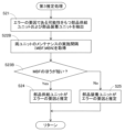
- FIG. 5 is a sub-operational flow diagram illustrating details of the estimation process executed by the estimation unit in step S8 of the operational flow of FIG.
- FIG. 5 is a diagram showing an operational flow of a response process executed by the error cause identification device following the operational flow of FIG. 4 .
- FIG. 13 is a diagram showing a sub-operation flow of a second estimation process using an error occurrence rate executed by the estimation unit.
- FIG. 13 is a diagram showing a sub-operation flow of a third estimation process using a maintenance implementation interval performed by an estimation unit.
- FIG. 13 is a diagram showing a sub-operation flow of a fourth estimation process using the next scheduled time of maintenance performed by the estimation unit.
- the component mounting machine 1 performs a mounting operation to mount components on a board K.
- the horizontal direction from the left to the right of the paper in Fig. 1 is the X-axis direction along which the board K is transported, the horizontal direction from the lower side (front side) to the upper side (rear side) of the paper is the Y-axis direction, and the vertical direction is the Z-axis direction.
- the component mounting machine 1 is configured by assembling a board transport device 2, a component supply device 3, a component transfer device 4, a control device 5, etc., on a base 10.
- the board transport device 2 has a pair of guide rails 21 that form a transport path for the board K.
- the board transport device 2 transports the board K that has been brought into the input end (left end in FIG. 1) of the guide rails 21 by the board input device or external transport device along the guide rails 21 to a predetermined stop position.
- the predetermined stop position for the board K is set approximately at the center of the transport direction of the transport path.
- the board transport device 2 has a positioning mechanism 22 that pushes up the board K at the stop position and clamps it between the guide rails 21.
- the component transfer device 4 performs a component mounting operation on the positioned board K. After the mounting operation is completed, the board transport device 2 transports the board K from the stop position to the output end (right end in FIG. 1) and removes it from the machine.
- the component supply device 3 is disposed at the front in the Y-axis direction on the top surface of the base 10.
- the component supply device 3 is composed of a plurality of component supply units 31 arranged in a line in the X-axis direction.
- Each of the component supply units 31 supplies components in the mounting operation, and corresponds to a component involved in the mounting operation.
- a tape feeder is used for the component supply unit 31.
- the tape feeder sends out a carrier tape on which a plurality of components are stored in a line toward a supply position at the tip side.
- the component supply unit 31 may be a tray feeder that uses a tray in which components are stored in a plurality of storage sections arranged in a grid pattern, or a stick feeder that stores components in a line inside a cylindrical stick.
- the component transfer device 4 is composed of a Y-axis moving body 41, an X-axis moving body 42, a mounting head 43, a rotary tool 44, multiple component mounting units 45, a board camera 46, and a component camera 47.
- the Y-axis moving body 41 is formed of a member that is long in the X-axis direction, and is driven by a Y-axis drive mechanism (not shown) to move in the Y-axis direction.
- the X-axis moving body 42 is mounted on the Y-axis moving body 41, and is driven by an X-axis drive mechanism (not shown) to move in the X-axis direction.
- the mounting head 43 is attached to the front of the X-axis moving body 42. The mounting head 43 is driven in two horizontal directions together with the X-axis moving body 42, and moves to above the component supply device 3 and above the board K.
- a rotary tool 44 is rotatably mounted below the mounting head 43.
- the rotary tool 44 is driven by an R-axis drive mechanism (not shown) to rotate about a vertical central axis.
- the rotary tool 44 holds multiple component mounting units 45 below it.
- Each of the component mounting units 45 picks up a component at the supply position of the component supply unit 31 and mounts it at the mounting position on the board K, and corresponds to a component involved in the mounting operation.
- a suction nozzle is used in the component mounting unit 45.
- the mounting head 43 and rotary tool 44 hold multiple suction nozzles and move between the component supply unit 31 and the board K, and correspond to a component involved in the mounting operation.
- the rotary tool 44 has 12 suction nozzles (component mounting units 45) at equal distances from the vertical center axis.
- the suction nozzles are driven by an unillustrated lifting drive mechanism to move up and down, and are driven by an unillustrated Q-axis drive mechanism to rotate about the vertical axis.
- the suction nozzles are further selectively supplied with negative pressure air and positive pressure air from the air supply mechanism.
- the suction nozzles perform a mounting operation of picking up components from the component supply unit 31 and mounting them on the board K.
- a plurality of mounting heads 43, rotary tools 44, and component mounting units 45 are prepared, and are automatically or manually replaced as necessary.
- the mounting head 43 may be provided with multiple suction nozzles 45 arranged in a row or in a lattice pattern without the rotary tool 44.
- the component mounting unit 45 is not limited to a suction nozzle, and may be a chuck that clamps and picks up a component.
- the board camera 46 is mounted facing downward on the X-axis moving body 42 alongside the mounting head 43.
- the board camera 46 captures an image of the position reference mark attached to the board K from above.
- the acquired image data is processed to accurately determine the stopping position of the board K.
- the component camera 47 is mounted facing upward on the base 10 between the board transport device 2 and the component supply device 3.
- the component camera 47 captures an image of the components picked up by the component mounting unit 45 from below while the mounting head 43 is moving from the component supply device 3 to the board K.
- the acquired image data is processed to determine whether the type of component is correct, and further, the position and orientation of the component relative to the component mounting unit 45 are detected and reflected in the mounting operation.
- the component camera 47 corresponds to a component involved in the mounting operation. Examples of the board camera 46 and the component camera 47 include digital imaging devices having imaging elements such as CCD (Charge Coupled Device) and CMOS (Complementary Metal Oxide Semiconductor).
- the component transfer device 4 performs the mounting operation by repeating a mounting cycle. To explain the mounting cycle in detail, the component transfer device 4 first moves the mounting head 43 to the component supply unit 31, where each of the multiple component mounting units 45 picks up a component. The component transfer device 4 then moves the mounting head 43 above the component camera 47. The component camera 47 then captures an image of the holding state of the components in the multiple component mounting units 45. The component transfer device 4 then moves the mounting head 43 to the board K and mounts the multiple components. The component transfer device 4 then moves the mounting head 43 back to the component supply unit 31, completing one mounting cycle.
- the control device 5 is attached to the base 10, and its position is not limited.
- the control device 5 is configured as a computer device having a CPU and operating on software.
- the control device 5 may be configured with multiple CPUs distributed within the machine and connected for communication.
- the control device 5 has a storage device 51 that stores various information.
- the control device 5 is connected for communication to the line management device 6.
- the control device 5 receives mounting job data 52 transferred from the line management device 6 and stores it in the storage device 51.
- the mounting job data 52 is data used in the mounting operation, and is created for each type of board K (board product).
- the mounting job data 52 includes board data relating to the shape etc. of the board K, and component data relating to the shape etc. of the components to be mounted on the board K.
- Each of the multiple pieces of component data included in the mounting job data 52 has the potential to cause an error in the mounting operation. This is similar to the fact that each of the multiple component supply units 31 that make up the component supply device 3 can potentially cause an error, and that each of the multiple component mounting units 45 held by the mounting head 43 can potentially cause an error.
- the mounting job data 52 also includes coordinate data of the supply position of the component supply unit 31, and coordinate data of the mounting position on the board K where the components are to be mounted. Furthermore, the mounting job data 52 includes data on the type and arrangement of the component supply unit 31 and component mounting unit 45 to be used, as well as detailed procedural data for the mounting operation. Based on the mounting job data 52, the control device 5 controls the board transport device 2, the component supply device 3, and the component transfer device 4 to repeat the mounting cycle and proceed with the mounting operation.
- the line management device 6 manages a board production line 7 that is configured by arranging a plurality of board-related operation machines, including the component mounting machine 1.
- the line management device 6 is configured using a computer device.
- the line management device 6 has an input device 61, such as a keyboard or a touch panel, that receives instructions and selection operations from workers, etc.
- the line management device 6 has a display device 62, such as a liquid crystal display, that displays various information to workers, etc.
- the line management device 6 is communicatively connected to the feeder maintenance device 77 and the nozzle maintenance device 78.
- the feeder maintenance device 77 receives the component supply unit 31 (tape feeder) and performs maintenance on it.
- the line management device 6 can obtain the maintenance implementation history performed by the feeder maintenance device 77 on the component supply unit 31. Furthermore, when regular maintenance is performed on the component supply unit 31, the line management device 6 can obtain the maintenance implementation interval and future implementation plan from the feeder maintenance device 77.
- the nozzle maintenance device 78 receives the component mounting unit 45 (suction nozzle) and performs maintenance on it.
- the line management device 6 can obtain the history of maintenance performed on the component mounting unit 45 by the nozzle maintenance device 78. Furthermore, when periodic maintenance is performed on the component mounting unit 45, the line management device 6 can obtain the maintenance interval and future maintenance plan from the nozzle maintenance device 78.
- maintenance of the component supply unit 31 (tape feeder) and the component mounting unit 45 (suction nozzle) may be performed by an operator. In this case, the operator may input the maintenance history into the line management device 6 using the input device 61, and may also input the maintenance interval and maintenance plan.
- the multiple substrate-related work machines that make up board production line 7 are, in order from the upstream side, a solder printer 71, a print inspection machine 72, a component mounting machine 1, a substrate visual inspection machine 73, and a reflow machine 74. These substrate-related work machines are connected via communication to line management device 6.
- the line configuration of board production line 7 can be changed in various ways.
- line management device 6 may manage multiple board production lines 7.
- the line management device 6 receives log data LD, which records a detailed history of the operating status, from each substrate-related operation machine in approximately real time.
- the data format of the log data LD may differ for each type of substrate-related operation machine, or may be unified.
- the log data LD of the component mounting machine 1 includes history information of each mounting operation that is performed multiple times.
- the log data LD of the component mounting machine 1 may also include transport history information related to the transport operation of the substrate K and replacement history information related to the replacement operation of the component parts.
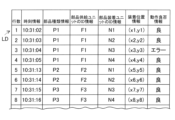
- FIG. 2 An example of the log data LD that the line management device 6 receives from the control device 5 of the component mounting machine 1 is shown in FIG. 2.
- Each row in FIG. 2 corresponds to one piece of log data LD.
- the log data LD related to the mounting operation of the component mounting machine 1 has a data format in which six pieces of information are associated. That is, the log data LD is associated with time information, component type information, ID information of the component supply unit 31, ID information of the component mounting unit 45, mounting position information, and operation success/failure information. Note that the row numbers 1 to 8 are added for the sake of convenience in order to distinguish and explain the eight pieces of log data LD.
- the data format of the log data LD of the component mounting machine 1 may also be modified as appropriate.
- the time information indicates the time (hour:minute:second) when the mounting operation was performed, and is represented, for example, by the timing when the component mounting unit 45 that mounted the component on the board K finished rising.
- the component type information indicates the type of component that was the subject of the mounting operation.
- the ID information of the component supply unit 31 is information that identifies the individual component supply unit 31 that supplied the component.
- the ID information of the component mounting unit 45 is information that identifies the individual component mounting unit 45 that picked up the component and mounted it on the board K.
- the ID information of the component supply unit 31 and the component mounting unit 45 corresponds to the operating condition information that indicates the components involved in each of the multiple mounting operations.
- the mounting position information is information that indicates the mounting position on the board K where the component is to be mounted in the X-Y coordinate system.
- the operation success/failure information is information that indicates the success/failure (good or error) of the operation result of the mounting operation of the component.
- the log data LD in line number 1 of Figure 2 is data related to the mounting operation at time 10:31:02.
- This log data LD indicates that a component of type P1 was supplied from component supply unit 31 with ID information F1, and mounted at mounting position (x1, y1) on board K by component mounting unit 45 with ID information N1. Furthermore, this log data LD indicates that the performance of the mounting operation for that component was good.
- the four log data LD in rows 1 to 4 indicate that four components of type P1 were supplied from the component supply unit 31 with ID information F1 and were mounted at four locations on board K by the four component mounting units 45 with ID information N1 to N4.
- the log data LD in rows 1, 2, and 4 indicate that the results of the mounting operations at mounting positions (x1, y1), (x2, y2), and (x4, y4) on board K were good.
- the log data LD in row 3 indicates that the result of the mounting operation at mounting position (x3, y3) on board K was an error. Note that for that mounting position (x3, y3), a recovery mounting cycle is set and the mounting operation of the components of type P1 is performed again.
- the two log data LDs on lines 5 and 6 indicate that two components of type P2 were supplied from a component supply unit 31 with ID information F2 and were mounted at two locations on board K by two component mounting units 45 with ID information N1 and N2. Furthermore, it is indicated that the results of the mounting operations at mounting positions (x5, y5) and (x6, y6) on board K were good.
- the two log data LDs on lines 7 and 8 indicate that two components of type P3 were supplied from a component supply unit 31 with ID information F3 and were mounted at two locations on board K by two component mounting units 45 with ID information N3 and N4. Furthermore, it is indicated that the results of the mounting operations at mounting positions (x7, y7) and (x8, y8) on board K were good.
- Examples of errors that may occur in the mounting operation include the following cases 1) to 7). 1) A case where image data was not acquired by the part camera 47. 2) Cases where image data was not properly processed. 3) A case in which it is determined as a result of image processing that the component mounting unit 45 is not holding a component. 4) Cases where image processing determined that the part type was incorrect. 5) As a result of image processing, the part orientation was found to be significantly incorrect, making it impossible to install. 6) A case in which a component falls off the component mounting unit 45 while the mounting head 43 is moving from the component camera 47 to the board K. 7) A case in which a component remains held in the component mounting unit 45 but is not mounted on the board K.
- the board visual inspection machine 73 judges an error to be present when there is an excessive error in the actual mounting position of the component mounted on the board K, when there is an excessive error in the orientation of the component (rotation within the horizontal plane), or when the component is mounted at an excessive angle.
- the board visual inspection machine 73 transmits log data LD including the error inspection results to the line management device 6.
- the line management device 6 extracts the log data LD of the corresponding component mounting machine 1 based on the mounting position information of the component judged to be an error, which is included in the log data LD of the board visual inspection machine 73, and rewrites the operation pass/fail information from good to error.
- the cause of the error in each of the above cases can be various, such as the component supply unit 31 or the component mounting unit 45 (components of the component mounting machine 1), or the mounting job data 52. It is also possible that the cause of the error is a component such as the mounting head 43, rotary tool 44, or component camera 47. In order to make the response more efficient and labor-saving when the number of errors of this kind increases, an error cause identification device 8 is used.
- the error factor identification device 8 is configured as one of the management function units of the line management device 6. However, without being limited to this, the error factor identification device 8 may be configured inside the control device 5 of the component mounting machine 1, or may be configured using another computer device.
- the error factor identification device 8 is configured with four function units, namely, a storage unit 81, an identification unit 82, an estimation unit 83, and a notification unit 84.
- the storage unit 81 stores the log data LD of the component mounting machine 1 in a memory or the like (not shown). In other words, the storage unit 81 stores operation quality information and operation condition information.
- the operation quality information is included in each of the log data LD illustrated in FIG. 2.
- the operation condition information is information indicating two or more of the multiple components of the component mounting machine 1 involved in each of the multiple mounting operations and the mounting job data 52.
- the information indicating the component supply unit 31 and the component mounting unit 45 in the operation condition information is included in each of the log data LD illustrated in FIG. 2.
- the information indicating the mounting head 43, the rotary tool 44, and the component camera 47 in the operation condition information is acquired from the log data LD including replacement history information of the components of the component mounting machine 1.
- the mounting job data 52 in the operation condition information has already been stored in the storage device 51.
- the identification unit 82 executes an identification process to identify the cause of an error when the error occurrence rate EC of the mounting operation exceeds a predetermined value E1 in the component mounting machine 1, any of the components of the component mounting machine 1, and at least one of the mounting job data 52, as a trigger condition.
- a predetermined value E1 can be set to, for example, 0.03% for the total number of operations of the component mounting machine 1, and 0.1% for the other number of operations.
- the identification unit 82 may collectively calculate the individual error occurrence rate EC for the multiple components and mounting job data 52 each time the component mounting machine 1 performs a mounting operation on a predetermined number of boards K, or each time the component mounting machine 1 has been in operation for a predetermined period of time. This allows the time periods of the populations when calculating the error occurrence rate EC for each of the multiple components and mounting job data 52 to be aligned, while the sizes of the multiple populations will differ.
- the identification unit 82 may also calculate the error occurrence rate EC for each of the multiple components and mounting job data 52 each time a predetermined number of times each component is involved in the mounting operation. For example, the identification unit 82 may calculate the error occurrence rate EC for each of the multiple component supply units 31 each time it operates 20,000 times, and may calculate the error occurrence rate EC for each of the multiple component mounting units 45 each time it operates 10,000 times. This allows the size of the population when calculating the error occurrence rate EC for each of the multiple components and mounting job data 52 to be aligned to a predetermined number of times, while the time periods of the multiple populations will differ.
- the identification unit 82 may execute the identification process using the number of times an error has occurred exceeding a predetermined value as a trigger condition, rather than the error occurrence rate EC.
- the identification unit 82 sets a population in the same way as when calculating the error occurrence rate EC, and determines the number of times an error has occurred within the population, but does not determine the cumulative number of times an error has occurred across the population.
- the identification unit 82 performs an identification process to compare the error contribution rates ER to identify the cause of the error. More specifically, the identification unit 82 first calculates two or more of the error contribution rate ER for each component and the error contribution rate ER of the mounting job data 52 based on the operation quality information and the operating condition information. The identification unit 82 then determines whether the error contribution rate ER is biased according to the differences in the individual components, with a different type of component or mounting job data 52 as the second cause, under conditions in which the individual components or mounting job data 52 with a high error contribution rate ER are identified as the first cause. If there is no bias, the identification unit 82 determines that the individual component with the identified first cause is the cause of the error.
- the identification unit 82 further determines whether the error contribution rate ER is biased according to the differences in the individuals of the first cause under conditions in which an individual of the second cause in which errors occur biased is identified. If there is no bias, the identification unit 82 sets the identified individual of the second cause as the cause of the error. According to this identification process, in cases where the error contribution rate ER is biased according to the differences in the individuals of the second cause under conditions in which an individual of the first cause is identified, and the error contribution rate ER is biased according to the differences in the individuals of the first cause under conditions in which an individual of the second cause is identified, the cause of the error is not identified.
- the component supply unit 31 and the component mounting unit 45 can be used as options for the first and second causes.
- multiple component data can be considered as different individuals and can be selected as options.
- options can be selected when log data LD including replacement history information exists and multiple individuals are used.
- the component camera 47 when capturing images by switching between multiple imaging conditions, the multiple imaging conditions can be considered as different individuals and can be selected as options.
- the error contribution rate ER is expressed as a ratio in which the total number of errors is the denominator and the number of errors that occurred in each of the multiple individuals included in the first or second cause is the numerator.
- whether or not the error contribution rate ER is biased is determined as follows. That is, the identification unit 82 determines that the error contribution rate ER is biased when the error contribution rate ER of one of the multiple individuals included in the first or second cause is equal to or greater than a predetermined contribution rate E2. The identification unit 82 also determines that the error contribution rate ER is not biased when the error contribution rate ER of each of the multiple individuals included in the first or second cause is less than the predetermined contribution rate E2.
- the predetermined contribution rate E2 can be set to, for example, 80%.
- the estimation unit 83 estimates the component or mounting job data 52 that is the cause of the error by using estimation logic that differs from the identification process of the identification unit 82, in other words, estimation logic that differs from the comparison of the error involvement rate ER.
- the estimation unit 83 operates only in cases where the identification unit 82 is unable to identify the cause of the error.
- the estimation unit 83 operates in cases where the identification unit 82 is unable to identify the cause of the error in the identification process in which the component supply unit 31 and the component mounting unit 45 are the first and second causes. Note that the estimation unit 83 may operate regardless of the success or failure of the identification process of the identification unit 82.
- the estimation unit 83 compares the last time maintenance was performed on the component supply unit 31 and the component mounting unit 45, which may be the cause of the error, and determines that the unit with the oldest last maintenance time is the cause of the error. In other words, the estimation unit 83 makes an estimation based on the basic idea (an idea based on empirical rules) that "units that have been maintained for a long time are more likely to experience performance degradation and become the cause of an error." Also, even if the mounting head 43 or the rotary tool 44 is selected as either the first or second cause, the estimation unit 83 can make an estimation by comparing the last time maintenance was performed. Note that the estimation logic of the estimation unit 83 may use a modified form described below.
- the notification unit 84 notifies the worker of the cause of the error identified by the identification unit 82 and the cause of the error estimated by the estimation unit 83.
- the notification unit 84 provides notification using the display device 62, and may also provide notification via wireless communication to the worker's mobile terminal as another notification method.
- two of the component supply unit 31, the component mounting unit 45, the mounting head 43, and the rotary tool 44 may be selected as the first cause and the second cause.
- the notification unit 84 notifies the worker to carry out maintenance for the cause of the error identified by the identification unit 82 and the cause of the error estimated by the estimation unit 83.
- the functions of the identification unit 82 and the estimation unit 83 cannot be said to be perfect, and there is a possibility that the cause of the error will be identified incorrectly.
- the error occurrence rate EC does not improve to below the predetermined value E1.
- the estimation unit 83 corrects the other of the component supply unit 31 and the component mounting unit 45 that is still in use to determine that it is the cause of the error.
- the notification unit 84 then notifies the user to carry out maintenance on the corrected cause of the error. Note that the function of the estimation unit 83 to correct the cause of the error may be omitted.
- the component mounting machine 1 uses a first nozzle N1, a second nozzle N2, a third nozzle N3, and a fourth nozzle N4, which correspond to four component mounting units 45 (suction nozzles).
- the component mounting machine 1 also uses five component supply units 31 (tape feeders) shown in parentheses. Specifically, the component mounting machine 1 uses a first feeder F1 that supplies components of type P1, a second feeder F2 that supplies components of type P2, a third feeder F3 that supplies components of type P3, a fourth feeder F4 that supplies components of type P4, and a fifth feeder F5 that supplies components of type P5.
- the component mounting machine 1 uses the first nozzle N1 to the fourth nozzle N4 to pick up four components of type P1 from the first feeder F1 and mount them on the board K.
- the component mounting machine 1 uses the first nozzle N1 and the second nozzle N2 to pick up two components of type P2 from the second feeder F2, and uses the third nozzle N3 and the fourth nozzle N4 to pick up two components of type P3 from the third feeder F3 and mounts them.
- the component mounting machine 1 uses the first nozzle N1 and the second nozzle N2 to pick up two components of type P4 from the fourth feeder F4, and uses the third nozzle N3 to pick up one component of type P5 from the fifth feeder F5 and mounts them.
- the component mounting machine 1 does not use the fourth nozzle N4.
- the identification unit 82 selects the component supply unit 31 and the component mounting unit 45 as the first and second causes. It is also assumed that the identification unit 82 collectively calculates the error occurrence rate EC for each individual component supply unit 31 and component mounting unit 45 each time the component mounting machine 1 performs mounting operations on 5,000 boards K. It is also assumed that the predetermined value E1 is set to 0.1% as a trigger condition for the identification unit 82 to execute the identification process. It is also assumed that the predetermined involvement rate E2, which determines whether the error involvement rate ER is biased, is set to 80%.
- step S1 of FIG. 4 the component mounting machine 1 executes the mounting operations of the first to third mounting cycles in order, then replaces the board K and continues the mounting operation.
- the memory unit 81 acquires and stores log data LD related to each mounting operation of the component mounting machine 1.
- the log data LD includes operation success/failure information and operating condition information for each mounting operation.
- the frequency of execution of this storage process may be every time one mounting operation is completed, every time one mounting cycle (3 to 4 mounting operations) is completed, or every time 11 mounting operations on one board K are completed.
- the identification unit 82 determines whether the time has come to calculate the error occurrence rate EC, and branches the operation flow. The calculation time has not come if the mounting operation for 5,000 substrates K has not been completed after the start of production of substrates K, or after the previous calculation time. In this case, the identification unit 82 returns the operation flow to step S1. Then, until the calculation time comes, the operation loop of steps S1 to S3 is repeated, and log data LD is accumulated. If the calculation time has come in step S3, the identification unit 82 advances the operation flow to step S4.
- step S4 the identification unit 82 calculates the error occurrence rate EC for each of the component supply unit 31 and the component mounting unit 45 collectively.
- the number of operations that constitutes the population when calculating the error occurrence rate EC is shown in FIG. 5.
- the number of operations for each of the component supply units 31 is 20,000 for the first feeder, 10,000 for the second feeder F2, the third feeder F3, and the fourth feeder F4, and 5,000 for the fifth feeder F5.
- the number of operations for each of the component mounting units 45 is 15,000 for the first nozzle N1, the second nozzle N2, and the third nozzle N3, and 10,000 for the fourth nozzle N4.
- the breakdown of the number of errors occurring for each individual component supply unit 31 is as follows: 1 for the first feeder, 22 for the second feeder F2, 1 for the third feeder F3, 0 for the fourth feeder F4, and 1 for the fifth feeder F5.
- the identification unit 82 divides these occurrence numbers by the number of operations of the population shown in FIG. 5 to calculate the error occurrence rate EC.
- the specific error occurrence rates EC are 0.01% for the first feeder, 0.22% for the second feeder F2, 0.01% for the third feeder F3, 0% for the fourth feeder F4, and 0.02% for the fifth feeder F5 (rounded off to the nearest 0.01%).
- the breakdown of the number of times errors occurred for each individual component mounting unit 45 is as follows: 9 times for the first nozzle N1, 13 times for the second nozzle N2, 2 times for the third nozzle N3, and 1 time for the fourth nozzle N4.
- the identification unit 82 calculates the error occurrence rate EC by dividing these occurrence numbers by the number of operations of the population shown in Figure 5.
- the specific error occurrence rates EC are 0.06% for the first nozzle N1, 0.09% for the second nozzle N2, 0.01% for the third nozzle N3, and 0.01% for the fourth nozzle N4.
- the predetermined value E1 may be set to 0.03% for the total number of operations of the component mounting machine 1 as a trigger condition for the identification unit 82 to execute the identification process.
- step S6 the identification unit 82 executes an identification process to identify the cause of the error.
- the identification unit 82 executes the identification process shown in the sub-operation flow of FIG. 7.
- step S11 of FIG. 7 the identification unit 82 calculates the individual error contribution rate ER of the component supply unit 31 and the component mounting unit 45.
- the identification unit 82 identifies an individual of the first cause with a high error contribution rate ER.
- the identification unit 82 selects the component supply unit 31 as the first cause, selects the component mounting unit 45 as the second cause, and identifies the second feeder F2 as the first cause with a high error contribution rate ER of 88%.
- the identification unit 82 determines whether there is a bias due to differences in the individual of the second cause. Under the conditions for identifying the second feeder F2, the total number of errors that occurred was 22, with 9 errors from the first nozzle N1 and 13 errors from the second nozzle N2.
- the identification unit 82 identifies the identified first cause, that is, the second feeder F2, as the cause of the error. To add to that, the second feeder F2, which has the highest number of errors, is naturally more likely to be the cause of the error. However, it cannot be denied that either of the component mounting units 45 used in combination may be the cause of the error.
- the error occurs not only in one of the first nozzle N1 or the second nozzle N2, but in both. It is extremely rare for the performance of the first nozzle N1 and the second nozzle N2 to deteriorate at the same time and become a cause of the error. Therefore, the identification unit 82 can identify that the error occurred due to a deterioration in the performance of the second feeder F2, and there is almost no risk of an erroneous identification result.
- the processing contents of the above-mentioned identification process are shown diagrammatically in the error cause identification diagram of FIG. 8.
- the vertical axis indicates the error contribution rate ER of the component supply unit 31, and the horizontal axis indicates the error contribution rate ER of the component mounting unit 45.
- the first region A1 is the region where the error contribution rates ER of the component supply unit 31 and the component mounting unit 45 are both less than the predetermined contribution rate E2.
- the second region A2 is the region where the error contribution rate ER of the component supply unit 31 is equal to or greater than the predetermined contribution rate E2 and the error contribution rate ER of the component mounting unit 45 is less than the predetermined contribution rate E2.
- the third region A3 is the region where the error contribution rate ER of the component supply unit 31 is less than the predetermined contribution rate E2 and the error contribution rate ER of the component mounting unit 45 is equal to or greater than the predetermined contribution rate E2.
- the fourth area A4 is the area where the error contribution rates ER of the component supply unit 31 and the component mounting unit 45 are both equal to or greater than the predetermined contribution rate E2.
- the identification unit 82 calculates the error contribution rate ER of the first nozzle N1 and the error contribution rate ER of the second nozzle N2 under the conditions in which the second feeder F2 is identified as described above.
- the calculation results are plotted as P1 (F2, N1) and P2 (F2, N2) in the error cause identification diagram.
- P1 (F2, N1) is plotted at the intersection of the error contribution rate ER of the second feeder F2 of 88% and the error contribution rate ER of the first nozzle N1 of 38% under the conditions in which the second feeder F2 is identified.
- the identification unit 82 when plots such as P1 (F2, N1) and P2 (F2, N2) indicating the processing contents of the identification unit 82 are included in the second area A2, the identification unit 82 can identify one of the component supply units 31 as the cause of the error. Furthermore, taking into account the duality between the component supply unit 31 and the component mounting unit 45, when the plot showing the processing content of the identification unit 82 is included in the third area A3, the identification unit 82 can identify one of the component mounting units 45 as the cause of the error.
- the identification unit 82 may select the component mounting unit 45 as the first factor, select the component supply unit 31 as the second factor, and identify the second nozzle N2 as the first factor with a high error contribution rate ER of 52%. Then, in the next step S13, the identification unit 82 determines whether or not there is a bias due to individual differences in the second factor under the conditions in which the second nozzle N2 is identified. Under the conditions in which the second nozzle N2 is identified, the total number of occurrences of errors is 13.
- the sub-operation flow branches to step S15.
- This processing is plotted as Q1 (N2, F1), Q2 (N2, F2), and Q3 (N2, F4) in the error cause identification diagram in Figure 8.
- step S15 the identification unit 82 identifies the second feeder F2, which is an individual of the second cause in which errors occurred unevenly.
- the identification unit 82 determines whether or not there is a bias according to differences in the individual of the first cause under the conditions in which the second feeder F2 was identified. Under the conditions in which the second feeder F2 was identified, the total number of times errors occurred is 22.
- the error contribution rate ER of the first nozzle N1, which is the first cause, is 38%
- the error contribution rate ER of the second nozzle N2 is 62%. Therefore, the error contribution rate ER is not uneven, and the sub-operation flow branches to step S17.
- step S17 the identification unit 82 identifies the identified second cause, i.e., the second feeder F2, as the cause of the error. In this way, even if the identification unit 82 executes an identification process in which the first cause and the second cause are swapped in the application example, it is possible to obtain the same identification result as in the first example.
- the sub-operation flow of the identification process ends with the execution of step S14 or step S17.
- the identification process of the identification unit 82 for the second example shown in FIG. 9 will be described.
- the breakdown of the number of errors for each individual component supply unit 31 is as follows: 1 for the first feeder, 22 for the second feeder F2, 1 for the third feeder F3, 0 for the fourth feeder F4, and 1 for the fifth feeder F5. Therefore, the error occurrence rates EC for each individual component supply unit 31 calculated by the identification unit 82 in step S4 are 0.01% for the first feeder, 0.22% for the second feeder F2, 0.01% for the third feeder F3, 0% for the fourth feeder F4, and 0.02% for the fifth feeder F5.
- the breakdown of the number of errors that occurred for each individual component mounting unit 45 is as follows: first nozzle N1: 2 times, second nozzle N2: 20 times, third nozzle N3: 2 times, and fourth nozzle N4: 1 time. Therefore, the error occurrence rates EC for each individual component mounting unit 45 calculated by the identification unit 82 are: first nozzle N1: 0.01%, second nozzle N2: 0.13%, third nozzle N3: 0.01%, and fourth nozzle N4: 0.01%.
- step S5 the identification unit 82 advances the operation flow to step S6 since the error occurrence rate EC of the second feeder F2 is 0.22%, which is equal to or greater than the predetermined value E1.
- step S11 of FIG. 7, which corresponds to the identification process of step S6, the identification unit 82 calculates the individual error contribution rates ER of the component supply units 31 as follows: 4% for the first feeder, 88% ( 22/25 ⁇ 100) for the second feeder F2, 4% for the third feeder F3, 0% for the fourth feeder F4, and 4% for the fifth feeder F5.
- the identification unit 82 selects the component supply unit 31 as the first cause and the component mounting unit 45 as the second cause, and identifies the second feeder F2 as the first cause with a high error contribution rate ER of 88%.
- step S15 the identification unit 82 identifies the second nozzle N2, which is an individual of the second cause in which the error occurred unevenly.
- the details of the identification process in the second example are shown diagrammatically in the error cause identification diagram of FIG. 10.
- the details of the processes in steps S12 and S13 of the identification unit 82 are plotted at P4 (F2, N1) and P5 (F2, N2) in the error cause identification diagram.
- the details of the processes in step S16 of the identification unit 82 are plotted at Q4 (N2, F1), Q5 (N2, F2), and Q6 (N2, F4) in the error cause identification diagram.
- P5 (F2, N2) and Q5 (N2, F2) which indicate the details of the processes in the identification unit 82, are included in the fourth area A4, the identification unit 82 cannot identify the cause of the error.
- the plot showing the processing content of the identification unit 82 is included in the first area A1, and the identification unit 82 is unable to identify the cause of the error.
- the identification unit 82 is unable to identify the cause of the error, but the estimation unit 83 is able to estimate the first unit that caused the error. Then, after the first unit is maintained and reused, or after a spare unit is used in place of the first unit, the identification unit 82 is able to identify the second unit that caused the error in the next identification process.
- the estimation unit 83 branches the operation flow depending on whether or not the identification unit 82 was able to identify the cause of the error. In cases where the identification unit 82 was able to identify the cause of the error, the estimation unit 83 skips step S8 and advances the operation flow to step S9. On the other hand, in cases where the identification unit 82 was unable to identify the cause of the error, the estimation unit 83 executes the estimation process shown in the sub-operation flow in FIG. 11 in step S8.
- the estimation unit 83 extracts the component supply unit 31 and the component mounting unit 45 that may be the cause of the error. For example, in the second case, the estimation unit 83 extracts the second feeder F2 and the second nozzle N2, where errors are occurring unevenly. In the next step S22, the estimation unit 83 obtains the final timing for maintenance of both units. That is, the estimation unit 83 obtains the final timing MAF for maintenance of the second feeder F2 from the feeder maintenance device 77. The estimation unit 83 also obtains the final timing MAN for maintenance of the second nozzle N2 from the nozzle maintenance device 78.
- step S23 the estimation unit 83 advances the sub-operation flow to step S24 if the last maintenance time MAF of the second feeder F2 is older than the last maintenance time MAN of the second nozzle N2, and advances the sub-operation flow to step S25 if not.
- step S24 the estimation unit 83 estimates that the second feeder F2 (component supply unit 31) is the cause of the error.
- step S25 the estimation unit 83 estimates that the second nozzle N2 (component mounting unit 45) is the cause of the error. In other words, the estimation unit estimates that the unit with the older last maintenance time is the cause of the error. This ends the sub-operation flow of the estimation process.
- the notification unit 84 notifies the identification unit 82 to carry out maintenance for the cause of the error identified by the identification unit 82. Furthermore, in cases where the identification unit 82 is unable to identify the cause of the error, the notification unit 84 notifies the estimation unit 83 to carry out maintenance for the cause of the error estimated by the estimation unit 83. This ends the operation flow shown in FIG. 4, and the error cause identification device 8 moves to the response process shown in FIG. 12.
- the notification unit 84 notifies the identification unit 82 to carry out maintenance for the second feeder F2 (one side) indicated by the estimation result of the estimation unit 83, out of the second feeder F2 (one side) and the second nozzle N2 (the other side) in which errors have occurred unevenly.
- step S31 of the response process shown in FIG. 12 the worker suspends operation of the component mounting machine 1 and removes the second feeder F2 for which maintenance has been notified.
- step S32 the worker transports the second feeder F2 to the feeder maintenance device 77 and performs maintenance on it.
- the worker installs the second feeder F2 for which maintenance has been completed in the component mounting machine 1 for reuse, and resumes operation of the component mounting machine 1.
- steps S1 to S4 in FIG. 4 are executed, and the identification unit 82 calculates the individual error occurrence rate EC of the second feeder F2.
- step S35 if the error occurrence rate EC has not improved, the estimation unit 83 corrects the error to the second nozzle N2 (the other one), which continues to be used, as the cause of the error.
- step S36 the notification unit 84 notifies the user to carry out maintenance on the second nozzle N2, which is the corrected cause of the error. This ends the operational flow of the response process.
- the worker removes the second nozzle N2 for which maintenance has been notified from the component mounting machine 1 and has the nozzle maintenance device 78 carry out the maintenance.
- the worker then re-installs the second nozzle N2 for which maintenance has been completed back into the component mounting machine 1 for reuse, and resumes operation of the component mounting machine 1.
- maintenance is carried out on both the second feeder F2 and the second nozzle N2, which may be the cause of the error, and therefore the occurrence of the error is improved in the majority of cases.
- step S33 the operator may equip the component mounting machine 1 with a spare sixth feeder F6 in place of the second feeder F2 for which maintenance has been notified, and resume operation of the component mounting machine 1.
- the cause of the error is the second feeder F2
- the error occurrence rate EC is improved, and the operation flow proceeds from step S34 to end.
- the cause of the error is something other than the second feeder F2, the error occurrence rate EC is not improved, and the operation flow proceeds from step S34 to step S35.
- step S35 the estimation unit 83 corrects the cause of the error to be the second nozzle N2, which has been continuously used.
- the notification unit 84 notifies the operator to carry out maintenance on the second nozzle N2. This ends the operation flow of the response process.
- the estimation process of the estimation unit 83 can be modified into a second estimation process shown in Fig. 13, a third estimation process shown in Fig. 14, and a fourth estimation process shown in Fig. 15.
- steps S21, S24, and S25 are the same as the estimation process described using Fig. 11, and the processing contents of steps S22 and S23 are changed.
- step S22A of the second estimation process shown in FIG. 13 the estimation unit 83 acquires the error occurrence rate ECF of the second feeder F2 (component supply unit 31) and the error occurrence rate ECN of the second nozzle N2 (component mounting unit 45) from the identification unit 82.
- step S23A if the error occurrence rate ECF of the second feeder F2 is higher than the error occurrence rate ECN of the second nozzle N2, the estimation unit 83 advances the sub-operation flow to step S24, and if not, advances the sub-operation flow to step S25.
- the estimation unit 83 makes an estimation based on the basic idea that "a unit with a high error occurrence rate is highly likely to be the cause of an error.” Note that the estimation unit 83 may acquire the number of error occurrences from the identification unit 82 instead of the error occurrence rate (ECF, ECN), compare the number of occurrences, and advance the sub-operation flow to step S24 or step S25.
- ECF error occurrence rate
- step S22B of the third estimation process shown in FIG. 14 the estimation unit 83 acquires the maintenance interval MBF of the second feeder F2 (component supply unit 31) from the feeder maintenance device 77.
- the estimation unit 83 also acquires the maintenance interval MBN of the second nozzle N2 (component mounting unit 45) from the nozzle maintenance device 78.
- step S23B if the maintenance interval MBF of the second feeder F2 is shorter than the maintenance interval MBN of the second nozzle N2, the estimation unit 83 advances the sub-operation flow to step S24, and if not, the sub-operation flow advances to step S25.
- the estimation unit 83 makes an estimation based on the basic idea that "for units that are prone to performance degradation and have a high probability of becoming a cause of errors, maintenance at short intervals is recommended.”
- step S22C of the fourth estimation process shown in FIG. 15 the estimation unit 83 acquires the next scheduled time MCF for maintenance of the second feeder F2 (component supply unit 31) from the feeder maintenance device 77.
- the estimation unit 83 also acquires the next scheduled time MCN for maintenance of the second nozzle N2 (component mounting unit 45) from the nozzle maintenance device 78.
- the estimation unit 83 advances the sub-operation flow to step S24, and if not, the sub-operation flow advances to step S25.
- the estimation unit 83 makes an estimation based on the basic idea that "units for which a long time has passed since the last maintenance and whose next scheduled time is approaching are more likely to experience performance degradation and cause errors."
- the memory unit 81 stores operation pass/fail information and operating condition information for each of the mounting operations executed multiple times in the component mounting machine 1. Furthermore, when the error occurrence rate EC of the mounting operation exceeds a predetermined value E1, the identification unit 82 compares two or more error contribution rates ER to identify the cause of the error, and the estimation unit 83 estimates the cause of the error using an estimation logic different from that of the identification unit 82.
- identify and estimate correspond to one form of “identify”, so that even in cases where the identification unit 82 is unable to identify (specify) the cause of the error, the estimation unit 83 can identify (estimate) the cause of the error, thereby reducing the number of cases where the cause of the error is not identified.
- the error factor identification device 8 of the embodiment functions similarly for actual operating conditions other than the assumed first and second cases, and also functions similarly under conditions different from the assumptions.
- the number of components mounted on the board K and the number of component supply units 31 and component mounting units 45 used are generally greater than those in the assumed cases.
- the population for calculating the error occurrence rate EC does not have to be 5,000 boards K.
- the predetermined value E1 and the predetermined participation rate E2 may be set to values different from those in the embodiment.
- the estimation unit 83 operates regardless of the success or failure of the identification process of the identification unit 82
- the identification result of the identification unit 82 and the estimation result of the estimation unit 83 do not necessarily always match.
- the notification unit 84 only needs to notify the cause of the matching error.
- the notification unit 84 will give priority to notifying the cause of the error identified by the identification unit 82, or will notify the two causes that do not match.
- the processing content of the identification process of the identification unit 82 can be modified as appropriate, and the estimation unit 83 is required to use inference logic that differs from the modified identification process of the identification unit 82.
- various other applications and modifications are possible for the embodiment and modified forms.
- Component placement machine 2 Board transport device 3: Component supply device 31: Component supply unit 4: Component transfer device 43: Placement head 45: Component placement unit 47: Component camera 5: Control device 52: Placement job data 6: Line management device 7: Board production line 73: Board appearance inspection machine 77: Feeder maintenance device 78: Nozzle maintenance device 8: Error cause identification device 81: Memory unit 82: Identification unit 83: Estimation unit 84: Notification unit LD: Log data EC, ECF, ECN: (error) occurrence rate ER: Error contribution rate E1: Predetermined value E2: Predetermined contribution rate MAF, MAN: Last implementation time MBF, MBN: Implementation interval MCF, MCN: Next scheduled time
Landscapes
- Engineering & Computer Science (AREA)
- Operations Research (AREA)
- Manufacturing & Machinery (AREA)
- Microelectronics & Electronic Packaging (AREA)
- Supply And Installment Of Electrical Components (AREA)
Abstract
Description
まず、実施形態のエラー要因識別装置8の適用対象となる部品装着機1の構成例について、図1中の平面図を参考にして説明する。部品装着機1は、基板Kに部品を装着する装着動作を実施する。図1の紙面左側から右側に向かう水平方向が基板Kを搬送するX軸方向、紙面下側(前側)から紙面上側(後側)に向かう水平方向がY軸方向、鉛直方向がZ軸方向となる。部品装着機1は、基板搬送装置2、部品供給装置3、部品移載装置4、および制御装置5などが基台10に組み付けられて構成される。
次に、部品装着機1を管理するライン管理装置6、および部品装着機1の動作履歴を記録したログデータLDについて説明する。ライン管理装置6は、部品装着機1を含む複数の対基板作業機が並んで構成された基板生産ライン7を管理する。ライン管理装置6は、コンピュータ装置を用いて構成される。ライン管理装置6は、作業者等の指令や選択操作などを受け付けるキーボードやタッチパネルなどの入力装置61を有する。さらに、ライン管理装置6は、種々の情報を作業者等に向けて表示する液晶ディスプレイなどの表示装置62を有する。
1)部品カメラ47で画像データが取得されなかったケース。
2)画像データが適正に画像処理されなかったケース。
3)画像処理の結果、部品装着ユニット45が部品を保持していないと判定されたケース。
4)画像処理の結果、部品の種類が誤っていると判定されたケース。
5)画像処理の結果、部品の姿勢の誤差が大きく装着動作が無理と判定されたケース。
6)装着ヘッド43が部品カメラ47から基板Kに移動する途中で、部品が部品装着ユニット45から落下したケース。
7)部品が部品装着ユニット45に保持されたままで、基板Kに装着されなかったケース。
次に、実施形態のエラー要因識別装置8の構成および機能について、図1中の機能ブロック図を参考にして説明する。エラー要因識別装置8は、ライン管理装置6の一つの管理機能部として構成される。これに限定されず、エラー要因識別装置8は、部品装着機1の制御装置5の内部に構成され、または、その他のコンピュータ装置を用いて構成されてもよい。エラー要因識別装置8は、四つの機能部、すなわち記憶部81、特定部82、推定部83、および通知部84で構成される。
次に、実施形態のエラー要因識別装置8の動作について、事例を想定しつつ図3~図12を参考にして説明する。動作の説明に先立ち、基板Kへの装着動作に関して次のように想定する。すなわち、基板Kは、合計で11個の部品が装着され、その内訳は種類P1の部品が4個、種類P2の部品が2個、種類P3の部品が2個、種類P4の部品が2個、および種類P5の部品が1個であると想定する。この想定に対応するために、部品装着機1は、図3に示された三つの装着サイクルの装着動作を実行する。
推定部83の推定処理は、図13に示される第2推定処理、図14に示される第3推定処理、および図15に示される第4推定処理に変形することができる。第2~第4推定処理において、ステップS21、ステップS24、およびステップS25は、図11を用いて説明した推定処理と同じであり、ステップS22およびステップS23の処理内容が変更される。
なお、実施形態のエラー要因識別装置8は、想定した第一事例および第二事例以外の実際の稼動状況に対して同様に機能し、かつ想定と異なる条件下でも同様に機能する。例えば、基板Kに装着される部品の個数や、部品供給ユニット31および部品装着ユニット45の使用数は、想定した事例よりも多数である場合が一般的である。また、エラーの発生率ECを算出する際の母集団は、5000枚の基板Kでなくともよい。さらに、所定値E1および所定関与率E2は、実施形態と相違する値が設定されてもよい。
Claims (15)
- 部品装着機において複数回にわたって実行された装着動作の各々の動作結果の良否を示す動作良否情報、ならびに、複数回の前記装着動作の各々に関与した前記部品装着機の複数の構成部材および装着ジョブデータのうち二つ以上を示す動作条件情報を記憶する記憶部と、
前記部品装着機、前記構成部材、および前記装着ジョブデータの少なくとも一つで前記装着動作のエラーの発生率または発生回数が所定値を超えた場合に、前記動作良否情報および前記動作条件情報に基づいて算出された前記構成部材ごとのエラー関与率および前記装着ジョブデータのエラー関与率のうち二つ以上を比較して、前記エラーの要因である前記構成部材または前記装着ジョブデータを特定する特定部と、
前記エラー関与率の比較と相違する所定の推定ロジックを用いて、前記エラーの要因である前記構成部材または前記装着ジョブデータを推定する推定部と、
を備えるエラー要因識別装置。 - 前記特定部は、前記エラー関与率が高い前記構成部材または前記装着ジョブデータを第一要因としてその個体を特定した条件下で、別種の前記構成部材または前記装着ジョブデータを第二要因としてその個体の違いに応じて前記エラー関与率が偏っていない場合に、特定した前記第一要因の個体を前記エラーの要因とする、請求項1に記載のエラー要因識別装置。
- 前記特定部は、前記第一要因の個体を特定した条件下で、前記第二要因の個体の違いに応じて前記エラー関与率が偏っている場合に、前記エラーが偏って発生した前記第二要因の個体を特定した条件下で、前記第一要因の個体の違いに応じて前記エラー関与率が偏っていないときに、特定した前記第二要因の個体を前記エラーの要因とする、請求項2に記載のエラー要因識別装置。
- 前記特定部は、前記第一要因または前記第二要因に含まれる複数の個体のうち一つの個体の前記エラー関与率が所定関与率以上である場合に前記エラー関与率が偏っていると判定する、請求項2または3に記載のエラー要因識別装置。
- 複数の前記構成部材は、前記装着動作で部品を供給する部品供給ユニット、および前記部品供給ユニットから前記部品を採取して基板に装着する部品装着ユニットを含み、
前記推定部は、前記エラーの要因である可能性をもつ前記部品供給ユニットおよび前記部品装着ユニットに実施されたメンテナンスの最終実施時期を比較して、前記最終実施時期が古い方のユニットを前記エラーの要因とする前記推定ロジックを用いる、
請求項1に記載のエラー要因識別装置。 - 複数の前記構成部材は、前記装着動作で部品を供給する部品供給ユニット、および前記部品供給ユニットから前記部品を採取して基板に装着する部品装着ユニットを含み、
前記推定部は、前記エラーの要因である可能性をもつ前記部品供給ユニットおよび前記部品装着ユニットの前記エラーの前記発生率または前記発生回数を比較して、前記発生率が高い方または前記発生回数が多い方のユニットを前記エラーの要因とする前記推定ロジックを用いる、
請求項1に記載のエラー要因識別装置。 - 複数の前記構成部材は、前記装着動作で部品を供給するとともに定期的にメンテナンスが実施される部品供給ユニット、および前記部品供給ユニットから前記部品を採取して基板に装着するとともに定期的にメンテナンスが実施される部品装着ユニットを含み、
前記推定部は、前記エラーの要因である可能性をもつ前記部品供給ユニットおよび前記部品装着ユニットの前記メンテナンスの実施間隔を比較して、前記実施間隔が短い方のユニットを前記エラーの要因とする前記推定ロジックを用いる、
請求項1に記載のエラー要因識別装置。 - 複数の前記構成部材は、前記装着動作で部品を供給するとともに定期的にメンテナンスが実施される部品供給ユニット、および前記部品供給ユニットから前記部品を採取して基板に装着するとともに定期的にメンテナンスが実施される部品装着ユニットを含み、
前記推定部は、前記エラーの要因である可能性をもつ前記部品供給ユニットおよび前記部品装着ユニットの前記メンテナンスの次回予定時期を比較して、前記次回予定時期が近い方のユニットを前記エラーの要因とする前記推定ロジックを用いる、
請求項1に記載のエラー要因識別装置。 - 前記推定部は、前記特定部が前記エラーの要因を特定できなかった場合に限って動作する、請求項1~3、5~8のいずれか一項に記載のエラー要因識別装置。
- 前記特定部が特定した前記エラーの要因、および前記推定部が推定した前記エラーの要因を通知する通知部を備える、請求項1~3、5~8のいずれか一項に記載のエラー要因識別装置。
- 前記特定部が特定した前記エラーの要因、および前記推定部が推定した前記エラーの要因のメンテナンスを実施するように通知する通知部を備える、請求項5~8のいずれか一項に記載のエラー要因識別装置。
- 前記推定部は、前記通知部が通知した前記エラーの要因に相当する前記部品供給ユニットおよび前記部品装着ユニットの一方に前記メンテナンスが実施されて再使用されても前記エラーの前記発生率または前記発生回数が前記所定値以下に改善されない場合に、前記部品供給ユニットおよび前記部品装着ユニットの他方が前記エラーの要因であると修正する前記推定ロジックを用い、
前記通知部は、修正された前記エラーの要因の前記メンテナンスを実施するように通知する、
請求項11に記載のエラー要因識別装置。 - 前記特定部は、前記部品装着機が所定数量の基板への前記装着動作を行うごとに、または前記部品装着機の稼動時間が所定時間経過するごとに、複数の前記構成部材および前記装着ジョブデータのうち二つ以上を対象として、個体別の前記エラーの前記発生率または前記発生回数を一括して求める、請求項1~3、5~8のいずれか一項に記載のエラー要因識別装置。
- 前記特定部は、複数の前記構成部材および前記装着ジョブデータのうち二つ以上を対象として、個体別に前記装着動作に関与する回数が所定回数経過するごとに前記エラーの前記発生率または前記発生回数を個別に求める、請求項1~3、5~8のいずれか一項に記載のエラー要因識別装置。
- 複数の前記構成部材は、前記装着動作で部品を供給する部品供給ユニット、前記部品供給ユニットから前記部品を採取して基板に装着する部品装着ユニット、前記部品装着ユニットを保持して前記部品供給ユニットと前記基板の間を移動する装着ヘッド、および前記部品装着ユニットに採取された前記部品を撮像する部品カメラのうち一つ以上を含む、請求項1~3のいずれか一項に記載のエラー要因識別装置。
Priority Applications (4)
| Application Number | Priority Date | Filing Date | Title |
|---|---|---|---|
| PCT/JP2023/021457 WO2024252651A1 (ja) | 2023-06-09 | 2023-06-09 | エラー要因識別装置 |
| DE112023006480.6T DE112023006480T5 (de) | 2023-06-09 | 2023-06-09 | Fehlerfaktor-Identifikationsvorrichtung |
| CN202380098988.7A CN121241669A (zh) | 2023-06-09 | 2023-06-09 | 错误原因识别装置 |
| JP2025525896A JPWO2024252651A1 (ja) | 2023-06-09 | 2023-06-09 |
Applications Claiming Priority (1)
| Application Number | Priority Date | Filing Date | Title |
|---|---|---|---|
| PCT/JP2023/021457 WO2024252651A1 (ja) | 2023-06-09 | 2023-06-09 | エラー要因識別装置 |
Publications (1)
| Publication Number | Publication Date |
|---|---|
| WO2024252651A1 true WO2024252651A1 (ja) | 2024-12-12 |
Family
ID=93795581
Family Applications (1)
| Application Number | Title | Priority Date | Filing Date |
|---|---|---|---|
| PCT/JP2023/021457 Ceased WO2024252651A1 (ja) | 2023-06-09 | 2023-06-09 | エラー要因識別装置 |
Country Status (4)
| Country | Link |
|---|---|
| JP (1) | JPWO2024252651A1 (ja) |
| CN (1) | CN121241669A (ja) |
| DE (1) | DE112023006480T5 (ja) |
| WO (1) | WO2024252651A1 (ja) |
Citations (3)
| Publication number | Priority date | Publication date | Assignee | Title |
|---|---|---|---|---|
| JP2008028032A (ja) * | 2006-07-19 | 2008-02-07 | Matsushita Electric Ind Co Ltd | サービス供給方法 |
| WO2018142532A1 (ja) * | 2017-02-02 | 2018-08-09 | 株式会社Fuji | 生産管理装置 |
| JP2021073732A (ja) * | 2021-02-04 | 2021-05-13 | 株式会社Fuji | 生産管理方法 |
-
2023
- 2023-06-09 CN CN202380098988.7A patent/CN121241669A/zh active Pending
- 2023-06-09 DE DE112023006480.6T patent/DE112023006480T5/de active Pending
- 2023-06-09 JP JP2025525896A patent/JPWO2024252651A1/ja active Pending
- 2023-06-09 WO PCT/JP2023/021457 patent/WO2024252651A1/ja not_active Ceased
Patent Citations (3)
| Publication number | Priority date | Publication date | Assignee | Title |
|---|---|---|---|---|
| JP2008028032A (ja) * | 2006-07-19 | 2008-02-07 | Matsushita Electric Ind Co Ltd | サービス供給方法 |
| WO2018142532A1 (ja) * | 2017-02-02 | 2018-08-09 | 株式会社Fuji | 生産管理装置 |
| JP2021073732A (ja) * | 2021-02-04 | 2021-05-13 | 株式会社Fuji | 生産管理方法 |
Also Published As
| Publication number | Publication date |
|---|---|
| JPWO2024252651A1 (ja) | 2024-12-12 |
| DE112023006480T5 (de) | 2026-04-09 |
| CN121241669A (zh) | 2025-12-30 |
Similar Documents
| Publication | Publication Date | Title |
|---|---|---|
| JP4952692B2 (ja) | 電子部品実装装置および電子部品実装方法 | |
| JP5440486B2 (ja) | 部品実装装置および部品実装装置における機種切替え方法 | |
| CN110168458B (zh) | 管理装置、安装关联装置及安装系统 | |
| US11259451B2 (en) | Production management device | |
| US11076520B2 (en) | Production management device for mounting components on multiple board types | |
| WO2012172715A1 (ja) | 段取り方法、部品実装方法および部品実装システム | |
| JP5980944B2 (ja) | 部品実装ラインの生産監視システム及び生産監視方法 | |
| JP2008186992A (ja) | 電子部品装着装置 | |
| JP6960575B2 (ja) | 部品実装システムにおける実装基板の製造方法および部品実装方法 | |
| JP2012134303A (ja) | 電子部品装着装置、および、電子部品装着方法 | |
| JP6684982B2 (ja) | 部品実装システムおよび部品実装方法 | |
| JP5281546B2 (ja) | 電子部品の装着方法、電子部品装着装置、電子部品装着装置の電子部品装着順序決定方法及び電子部品装着装置の装着データ作成方法 | |
| JP7578831B2 (ja) | 部品実装システム | |
| JP5713441B2 (ja) | 部品実装システム | |
| CN114208412B (zh) | 安装装置、安装系统以及检查安装方法 | |
| JPWO2020003383A1 (ja) | 部品供給ユニットの配置決定方法および部品実装システム | |
| JP4425529B2 (ja) | 電子回路部品装着方法および電子回路部品装着システム | |
| JP6139948B2 (ja) | 部品実装装置 | |
| JP7061703B2 (ja) | 生産管理方法 | |
| CN121241669A (zh) | 错误原因识别装置 | |
| JP6293465B2 (ja) | 電子部品装着装置 | |
| JP7826233B2 (ja) | 部品実装システム | |
| JP7179211B2 (ja) | 実装システム及びエラー対処方法 | |
| WO2023281750A1 (ja) | 部品実装機及び異常判断方法 | |
| WO2025126372A1 (ja) | 部品実装システム |
Legal Events
| Date | Code | Title | Description |
|---|---|---|---|
| 121 | Ep: the epo has been informed by wipo that ep was designated in this application |
Ref document number: 23940749 Country of ref document: EP Kind code of ref document: A1 |
|
| ENP | Entry into the national phase |
Ref document number: 2025525896 Country of ref document: JP Kind code of ref document: A |
|
| WWE | Wipo information: entry into national phase |
Ref document number: 2025525896 Country of ref document: JP |
|
| WWE | Wipo information: entry into national phase |
Ref document number: 112023006480 Country of ref document: DE |
|
| WWP | Wipo information: published in national office |
Ref document number: 112023006480 Country of ref document: DE |