WO2024252552A1 - モータ制御装置 - Google Patents
モータ制御装置 Download PDFInfo
- Publication number
- WO2024252552A1 WO2024252552A1 PCT/JP2023/021142 JP2023021142W WO2024252552A1 WO 2024252552 A1 WO2024252552 A1 WO 2024252552A1 JP 2023021142 W JP2023021142 W JP 2023021142W WO 2024252552 A1 WO2024252552 A1 WO 2024252552A1
- Authority
- WO
- WIPO (PCT)
- Prior art keywords
- speed
- value
- axis current
- command value
- synchronous motor
- Prior art date
- Legal status (The legal status is an assumption and is not a legal conclusion. Google has not performed a legal analysis and makes no representation as to the accuracy of the status listed.)
- Ceased
Links
Images

Classifications
-
- H—ELECTRICITY
- H02—GENERATION; CONVERSION OR DISTRIBUTION OF ELECTRIC POWER
- H02P—CONTROL OR REGULATION OF ELECTRIC MOTORS, ELECTRIC GENERATORS OR DYNAMO-ELECTRIC CONVERTERS; CONTROLLING TRANSFORMERS, REACTORS OR CHOKE COILS
- H02P21/00—Arrangements or methods for the control of electric machines by vector control, e.g. by control of field orientation
- H02P21/14—Estimation or adaptation of machine parameters, e.g. flux, current or voltage
- H02P21/18—Estimation of position or speed
-
- H—ELECTRICITY
- H02—GENERATION; CONVERSION OR DISTRIBUTION OF ELECTRIC POWER
- H02P—CONTROL OR REGULATION OF ELECTRIC MOTORS, ELECTRIC GENERATORS OR DYNAMO-ELECTRIC CONVERTERS; CONTROLLING TRANSFORMERS, REACTORS OR CHOKE COILS
- H02P25/00—Arrangements or methods for the control of AC motors characterised by the kind of AC motor or by structural details
- H02P25/02—Arrangements or methods for the control of AC motors characterised by the kind of AC motor or by structural details characterised by the kind of motor
- H02P25/022—Synchronous motors
-
- H—ELECTRICITY
- H02—GENERATION; CONVERSION OR DISTRIBUTION OF ELECTRIC POWER
- H02P—CONTROL OR REGULATION OF ELECTRIC MOTORS, ELECTRIC GENERATORS OR DYNAMO-ELECTRIC CONVERTERS; CONTROLLING TRANSFORMERS, REACTORS OR CHOKE COILS
- H02P6/00—Arrangements for controlling synchronous motors or other dynamo-electric motors using electronic commutation dependent on the rotor position; Electronic commutators therefor
- H02P6/14—Electronic commutators
- H02P6/16—Circuit arrangements for detecting position
- H02P6/18—Circuit arrangements for detecting position without separate position detecting elements
- H02P6/182—Circuit arrangements for detecting position without separate position detecting elements using back-emf in windings
Definitions
- the present invention relates to a motor control device.
- a known method of controlling motor speed is vector control, which adjusts the magnetic flux current (d-axis current) that is in phase with the rotor and the torque current (q-axis current) that is 90° out of phase with the rotor.
- the rotor position can be detected by a sensor such as an encoder.
- sensorless vector control which estimates the rotor position and performs vector control, has the advantage of simplifying the motor configuration.
- a widely used method for estimating the rotor position is to use an extended electromotive force observer, that is, to estimate the extended electromotive force using an extended electromotive force model (see, for example, Non-Patent Document 1).
- the extended electromotive force model cannot accurately estimate the rotor position in the low-speed range where the induced voltage is small.
- the q-axis current is set to zero, so a large torque cannot be obtained, and the motor acceleration cannot be increased. For this reason, a motor control device with high acceleration and deceleration performance in the low speed range is desired.
- a motor control device is a motor control device that performs sensorless vector control of a synchronous motor, and includes an induced voltage estimation unit that estimates an induced voltage of the synchronous motor, a speed estimation unit that estimates the speed of the synchronous motor based on the induced voltage estimated by the induced voltage estimation unit, a speed control unit that generates a d-axis current command value and a q-axis current command value by receiving feedback of the speed estimated by the speed estimation unit so as to realize the synchronous motor speed specified by a speed command value, a d-axis current control unit that controls the d-axis current value of the synchronous motor to match the d-axis current command value, a q-axis current control unit that controls the q-axis current value of the synchronous motor to match the q-axis current command value, and an offset addition unit that adds an offset value to the d-axis current command value output from the speed control unit.
- FIG. 1 is a block diagram showing a configuration of a motor control device according to an embodiment of the present disclosure.
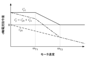
- 4 is a graph illustrating a relationship between a d-axis current command value and a rotation speed of the motor control device of FIG. 1 .
- FIG. 1 is a block diagram showing the configuration of a motor control device 1 according to one embodiment of the present disclosure.
- the motor control device 1 is a device that performs sensorless vector control of a synchronous motor 2, and controls the output of an inverter 3 that supplies power to the synchronous motor 2.
- the motor control device 1 also performs sensorless vector control in the low speed range.
- the motor control device 1 includes a speed control unit 11, a d-axis current control unit 12, a q-axis current control unit 13, a two-phase/three-phase conversion unit 14, a three-phase/two-phase conversion unit 15, an induced voltage estimation unit 16, a speed estimation unit 17, a position calculation unit 18, an offset addition unit 19, and a saturation adjustment unit 20.
- the speed control unit 11 receives a speed command value ⁇ * that specifies the speed of the synchronous motor 2, and generates a d-axis current command value i * ⁇ 0 that specifies the magnitude of the d-axis ( ⁇ -axis) component of the current input to the synchronous motor 2 and a q-axis current command value i * ⁇ that specifies the magnitude of the q-axis ( ⁇ -axis) component of the current input to the synchronous motor 2.
- the "d-axis in the control” and the "q-axis in the control” are simply referred to as the "d-axis" and the "q-axis”.
- the speed control unit 11 receives feedback of the speed ⁇ ⁇ estimated by a speed estimation unit 17 described later so as to realize the speed of the synchronous motor 2 specified by the speed command value ⁇ *, and calculates the d-axis current command value i * ⁇ 0 and the q-axis current command value i * ⁇ .
- the configuration of the speed control unit 11 can be the same as that in a conventional motor control device.
- " * " is added to the command value and " ⁇ " is added to the estimated value according to convention.
- the d-axis current control unit 12 calculates a d-axis voltage command value v * ⁇ that specifies a d-axis voltage value that can output a d-axis current that coincides with the d-axis current command value i* ⁇ output from the speed control unit 11 and after an offset is added by the offset adder 19 and the saturation adjuster 20.
- the d-axis current control unit 12 calculates the d-axis voltage command value v * ⁇ by receiving feedback of the value of the d-axis current actually applied to the synchronous motor 2, that is, the d-axis current value i ⁇ calculated by the three-phase/ two -phase conversion unit 1 from the current value of the synchronous motor 2.
- the configuration of the d-axis current control unit 12 can be the same as that in a conventional motor control device, and can be configured to perform, for example, PI control.
- the q-axis current control unit 13 calculates a q-axis voltage command value v * ⁇ that specifies a value of a q-axis voltage that can output a q-axis current that coincides with the q-axis current command value i* ⁇ output from the speed control unit 11.
- the q-axis current control unit 13 calculates the q-axis voltage command value v* ⁇ by receiving feedback of the q-axis current value i ⁇ calculated by the three-phase/two-phase conversion unit 1 from the current value of the synchronous motor 2.
- the configuration of the q-axis current control unit 13 may be the same as that in a conventional motor control device, and may be configured to perform, for example, PI control.
- the two-phase/three-phase converter 14 converts two-phase voltage commands, the d-axis voltage command value v * ⁇ output from the d-axis current controller 12 and the q-axis voltage command value v * ⁇ output from the q-axis current controller 13, into voltage command values v * u , v * v , and v * w for each phase of the three-phase voltage to be input to the synchronous motor 2.
- the configuration of the two-phase/three-phase converter 14 can be the same as that in a conventional motor control device.
- the three-phase/two-phase converter 15 performs dq conversion on the detected values of the three-phase currents (current values of at least two phases) supplied to the synchronous motor 2, and calculates the actual d-axis current value i ⁇ and q-axis current value i ⁇ .
- the configuration of the three-phase/two-phase converter 15 can be the same as that in a conventional motor control device.
- the induced voltage estimator 16 estimates the d-axis extended induced voltage e ⁇ ⁇ and the q-axis extended induced voltage e ⁇ ⁇ for control of the synchronous motor 2 from the d-axis voltage command value v * ⁇ output from the d-axis current control unit 12, the q-axis voltage command value v* ⁇ output from the q-axis current control unit 13, and the actual d-axis current value i ⁇ and q-axis current value i ⁇ calculated by the three-phase/two-phase conversion unit 15.
- the induced voltage estimator 16 can be configured by a well-known extended induced voltage observer.
- the speed estimator 17 estimates the actual speed ⁇ of the synchronous motor 2 based on the d-axis extended induced voltage e ⁇ ⁇ and the q-axis extended induced voltage e ⁇ ⁇ estimated by the induced voltage estimator.
- the speed estimator 17 may have a configuration similar to that of a conventional motor control device.
- the position calculation unit 18 estimates the actual rotational angle position ⁇ of the synchronous motor 2 from the actual speed ⁇ of the synchronous motor 2 estimated by the speed estimation unit 17.
- the configuration of the position calculation unit 18 can be the same as that in a conventional motor control device, and can be configured to estimate the rotational angle position ⁇ by integrating the rotational angle position ⁇ (transfer function 1/s), for example.
- the offset adder 19 adds an offset value i * ⁇ 1 to the d-axis current command value i * ⁇ 0 output from the speed control unit 11.
- the offset value i * ⁇ 1 can be adjusted by a saturation adjuster 20 (described later) so as not to exceed the current value permitted by the synchronous motor 2 and the inverter 3, but the offset adder 19 generates an offset value i * ⁇ 1 that does not take into account such equipment limitations. Therefore, the offset adder 19 can be configured to determine the offset value based only on the speed command value ⁇ * input to the speed control unit 11 or the speed ⁇ estimated by the speed estimator 17.
- the offset adding unit 19 is preferably configured to set a first speed threshold ⁇ T1 and a second speed threshold ⁇ T2 larger than the first speed threshold ⁇ T1 in advance, set the offset value i * ⁇ 1 to a constant value when the absolute value of the speed command value ⁇ * or the speed ⁇ ⁇ is less than the first speed threshold ⁇ T1 (offset control), set the offset value i * ⁇ 1 to a value that monotonically decreases with an increase in the absolute value of the speed command value ⁇ * or the speed ⁇ when the absolute value of the speed command value ⁇ * or the speed ⁇ is equal to or greater than the first speed threshold ⁇ T1 and equal to or less than the second speed threshold ⁇ T2 (transition control), and set the offset value i * ⁇ 1 to 0 when the absolute value of the speed command value ⁇ * or the speed ⁇ exceeds the second speed threshold ⁇ T2 (normal sensorless vector control).
- the second speed threshold ⁇ T2 can be set to a lower limit speed that is considered to be appropriately controlled by normal sensorless vector control, and the first speed threshold ⁇ T1 is preferably set so that the offset control and the sensorless vector control can be smoothly switched even when the speed change is large.
- the monotonic decrease when the absolute value of the speed command value ⁇ * or the speed ⁇ is equal to or greater than the first speed threshold value ⁇ T1 and equal to or less than the second speed threshold value ⁇ T2 may have any profile, such as a quadratic curve.
- the d-axis current command value i * ⁇ 0 output by the speed control unit 11 is a negative value proportional to the speed in order to utilize reluctance torque or apply flux-weakening control. In this way, when the speed is extremely low, the offset value i * ⁇ 1 ensures a certain amount of d-axis current and forms sufficient magnetic flux, so that step-out does not easily occur even if the error in the speed ⁇ becomes large.
- the saturation adjustment unit 20 adjusts the offset value i * ⁇ 1 so that the norm of the vector sum does not exceed the norm threshold, preferably so that the norm of the vector sum matches the norm threshold, and adds the adjusted offset value i * ⁇ 2 to the d-axis current command value i * ⁇ 0 output by the speed control unit 11.
- the saturation adjustment unit 20 can be configured to set the smaller of the offset value ⁇ (i a 2 -i * ⁇ 2 ) 1/2 -i * ⁇ 0 ⁇ where the norm of the vector sum ⁇ ( i * ⁇ 2 +i * ⁇ 2 ) 1/2 ⁇ coincides with the norm threshold i a and the offset value i * ⁇ 1 calculated by the offset addition unit 19 as an adjusted offset value i * ⁇ 2 to be added to the d-axis current command value i * ⁇ 0 output by the speed control unit 11.
- This makes it possible to protect the device by preventing the generation of a command value requesting a current that exceeds the capabilities of the synchronous motor 2 and the inverter 3, and to prevent operation stop due to the activation of a safety device such as a current trip.
- the motor control device 1 having the above configuration performs sensorless vector control using the d-axis current command value i * ⁇ 0 and the q-axis current command value i * ⁇ calculated by the speed control unit 11 even in the low speed range, and therefore ensures acceleration/deceleration performance by applying a q-axis current according to the q-axis current command value i * ⁇ that generates torque in the synchronous motor 2.
- the motor control device 1 adds an offset value i * ⁇ 1 to the d-axis current command value i * ⁇ 0 to ensure a certain level of d-axis current and form a sufficient magnetic flux, so that step-out does not easily occur even when the error in the speed ⁇ becomes large.
- a motor control device (1) is a motor control device (1) that performs sensorless vector control of a synchronous motor, an induced voltage estimation unit (16) for estimating an induced voltage of a synchronous motor (2); a speed estimation unit (17) that estimates a speed of the synchronous motor (2) based on the induced voltage estimated by the induced voltage estimation unit (16); a speed control unit (11) that receives feedback of a speed estimated by a speed estimation unit (17) and generates a d-axis current command value and a q-axis current command value so as to realize a speed of a synchronous motor (2) designated by the speed command value; a d-axis current control unit (12) that controls a value of a d-axis current of a synchronous motor (2) so that the value coincides with a d-axis current command value; a q-axis current control unit (13) that controls a value of a q-axis current of
- the offset addition unit (19) may be configured so that a first speed threshold and a second speed threshold greater than the first speed threshold are set in advance, and when the speed command value or the absolute value of the speed is less than the first speed threshold, the offset value is set to a constant value, when the speed command value or the absolute value of the speed is equal to or greater than the first speed threshold and equal to or less than the second speed threshold, the offset value is set to a value that monotonically decreases as the speed command value or the absolute value of the speed increases, and when the speed command value or the absolute value of the speed exceeds the second speed threshold, the offset value is set to 0.
- the motor control device (1) of Supplementary Note 1 or 2 may further include a saturation adjustment unit (20) that, when the norm of a vector sum of the d-axis current command value and the q-axis current command value to which the offset value has been added exceeds a predetermined norm threshold, adjusts at least one of the offset value, the d-axis current command value, and the q-axis current command value so that the norm of the vector sum does not exceed the norm threshold.
- a saturation adjustment unit (20) that, when the norm of a vector sum of the d-axis current command value and the q-axis current command value to which the offset value has been added exceeds a predetermined norm threshold, adjusts at least one of the offset value, the d-axis current command value, and the q-axis current command value so that the norm of the vector sum does not exceed the norm threshold.
- the saturation adjustment unit (20) may adjust the offset value so that the norm of the vector sum coincides with a norm threshold value.
- the saturation adjustment unit can be omitted.
- the saturation adjustment unit may adjust at least one of the d-axis current command value and the q-axis current command value output by the speed control unit.
Landscapes
- Engineering & Computer Science (AREA)
- Power Engineering (AREA)
- Control Of Ac Motors In General (AREA)
Abstract
Description
(付記1)
モータ制御装置(1)は、同期モータをセンサレスベクトル制御するモータ制御装置(1)であって、
同期モータ(2)の誘起電圧を推定する誘起電圧推定部(16)と、
誘起電圧推定部(16)が推定した誘起電圧に基づいて同期モータ(2)の速度を推定する速度推定部(17)と、
速度指令値が指定する同期モータ(2)の速度を実現するよう、速度推定部(17)が推定した速度のフィードバックを受けてd軸電流指令値及びq軸電流指令値を生成する速度制御部(11)と、
同期モータ(2)のd軸電流の値をd軸電流指令値に一致させるよう制御するd軸電流制御部(12)と、
同期モータ(2)のq軸電流の値をq軸電流指令値に一致させるよう制御するq軸電流制御部(13)と、
速度制御部(11)から出力されるd軸電流指令値にオフセット値を加算するオフセット加算部(19)と、
を備える。
付記1のモータ制御装置(1)において、オフセット加算部(19)は、予め第1速度閾値と第1速度閾値よりも大きい第2速度閾値が設定され、速度指令値又は速度の絶対値が第1速度閾値未満のときは、オフセット値を一定値とし、速度指令値又は速度の絶対値が第1速度閾値以上第2速度閾値以下であるときは、オフセット値を速度指令値又は速度の絶対値の増大に伴って単調減少する値とし、速度指令値又は速度の絶対値が第2速度閾値を超えるときは、オフセット値を0としてもよい。
付記1又は2のモータ制御装置(1)は、オフセット値を加算したd軸電流指令値とq軸電流指令値のベクトル和のノルムが所定のノルム閾値を超える場合、ベクトル和のノルムがノルム閾値を超えないよう、オフセット値、d軸電流指令値及びq軸電流指令値の少なくともいずれかを調整する飽和調整部(20)をさらに備えてもよい。
付記3のモータ制御装置(1)において、飽和調整部(20)は、ベクトル和のノルムがノルム閾値に一致するようオフセット値を調整してもよい。
2 同期モータ
3 インバータ
11 速度制御部
12 d軸電流制御部
13 q軸電流制御部
14 2相/3相変換部
15 3相/2相変換部
16 誘起電圧推定部
17 速度推定部
18 位置算出部
19 オフセット加算部
20 飽和調整部
Claims (4)
- 同期モータをセンサレスベクトル制御するモータ制御装置であって、
前記同期モータの誘起電圧を推定する誘起電圧推定部と、
前記誘起電圧推定部が推定した誘起電圧に基づいて前記同期モータの速度を推定する速度推定部と、
速度指令値が指定する前記同期モータの速度を実現するよう、前記速度推定部が推定した速度のフィードバックを受けてd軸電流指令値及びq軸電流指令値を生成する速度制御部と、
前記同期モータのd軸電流の値を前記d軸電流指令値に一致させるよう制御するd軸電流制御部と、
前記同期モータのq軸電流の値を前記q軸電流指令値に一致させるよう制御するq軸電流制御部と、
前記速度制御部から出力される前記d軸電流指令値にオフセット値を加算するオフセット加算部と、
を備える、モータ制御装置。 - 前記オフセット加算部は、
予め第1速度閾値と前記第1速度閾値よりも大きい第2速度閾値が設定され、
前記速度指令値又は前記速度の絶対値が前記第1速度閾値未満のときは、前記オフセット値を一定値とし、
前記速度指令値又は前記速度の絶対値が前記第1速度閾値以上前記第2速度閾値以下であるときは、前記オフセット値を前記速度指令値又は前記速度の絶対値の増大に伴って単調減少する値とし、
前記速度指令値又は前記速度の絶対値が前記第2速度閾値を超えるときは、前記オフセット値を0とする、請求項1に記載のモータ制御装置。 - 前記オフセット値を加算した前記d軸電流指令値と前記q軸電流指令値のベクトル和のノルムが所定のノルム閾値を超える場合、前記ベクトル和のノルムが前記ノルム閾値を超えないよう、前記オフセット値、前記d軸電流指令値及び前記q軸電流指令値の少なくともいずれかを調整する飽和調整部をさらに備える、請求項1又は2に記載のモータ制御装置。
- 前記飽和調整部は、前記ベクトル和のノルムが前記ノルム閾値に一致するよう前記オフセット値を調整する、請求項3に記載のモータ制御装置。
Priority Applications (4)
| Application Number | Priority Date | Filing Date | Title |
|---|---|---|---|
| CN202380098759.5A CN121263953A (zh) | 2023-06-07 | 2023-06-07 | 电动机控制装置 |
| PCT/JP2023/021142 WO2024252552A1 (ja) | 2023-06-07 | 2023-06-07 | モータ制御装置 |
| DE112023005820.2T DE112023005820T5 (de) | 2023-06-07 | 2023-06-07 | Motorsteuervorrichtung |
| JP2025525520A JPWO2024252552A1 (ja) | 2023-06-07 | 2023-06-07 |
Applications Claiming Priority (1)
| Application Number | Priority Date | Filing Date | Title |
|---|---|---|---|
| PCT/JP2023/021142 WO2024252552A1 (ja) | 2023-06-07 | 2023-06-07 | モータ制御装置 |
Publications (1)
| Publication Number | Publication Date |
|---|---|
| WO2024252552A1 true WO2024252552A1 (ja) | 2024-12-12 |
Family
ID=93795587
Family Applications (1)
| Application Number | Title | Priority Date | Filing Date |
|---|---|---|---|
| PCT/JP2023/021142 Ceased WO2024252552A1 (ja) | 2023-06-07 | 2023-06-07 | モータ制御装置 |
Country Status (4)
| Country | Link |
|---|---|
| JP (1) | JPWO2024252552A1 (ja) |
| CN (1) | CN121263953A (ja) |
| DE (1) | DE112023005820T5 (ja) |
| WO (1) | WO2024252552A1 (ja) |
Citations (3)
| Publication number | Priority date | Publication date | Assignee | Title |
|---|---|---|---|---|
| JP2010063336A (ja) * | 2008-09-08 | 2010-03-18 | Denso Corp | 回転機の制御装置 |
| JP2017046397A (ja) * | 2015-08-25 | 2017-03-02 | 富士電機株式会社 | 電力変換装置 |
| JP2017046391A (ja) * | 2015-08-25 | 2017-03-02 | 富士電機株式会社 | 電力変換装置 |
-
2023
- 2023-06-07 WO PCT/JP2023/021142 patent/WO2024252552A1/ja not_active Ceased
- 2023-06-07 CN CN202380098759.5A patent/CN121263953A/zh active Pending
- 2023-06-07 JP JP2025525520A patent/JPWO2024252552A1/ja active Pending
- 2023-06-07 DE DE112023005820.2T patent/DE112023005820T5/de active Pending
Patent Citations (3)
| Publication number | Priority date | Publication date | Assignee | Title |
|---|---|---|---|---|
| JP2010063336A (ja) * | 2008-09-08 | 2010-03-18 | Denso Corp | 回転機の制御装置 |
| JP2017046397A (ja) * | 2015-08-25 | 2017-03-02 | 富士電機株式会社 | 電力変換装置 |
| JP2017046391A (ja) * | 2015-08-25 | 2017-03-02 | 富士電機株式会社 | 電力変換装置 |
Also Published As
| Publication number | Publication date |
|---|---|
| JPWO2024252552A1 (ja) | 2024-12-12 |
| DE112023005820T5 (de) | 2025-12-04 |
| CN121263953A (zh) | 2026-01-02 |
Similar Documents
| Publication | Publication Date | Title |
|---|---|---|
| JP6014401B2 (ja) | 電動機制御装置 | |
| JP5957704B2 (ja) | 電動機制御装置 | |
| JP5257365B2 (ja) | モータ制御装置とその制御方法 | |
| JP3860031B2 (ja) | 同期電動機制御装置、同期電動機の制御方法 | |
| TWI587622B (zh) | Drive system and inverter device | |
| JP5948613B2 (ja) | モータの制御装置 | |
| JP6008264B2 (ja) | 永久磁石型同期電動機の磁極位置検出装置 | |
| JP4797074B2 (ja) | 永久磁石モータのベクトル制御装置、永久磁石モータのベクトル制御システム、及びスクリュー圧縮器 | |
| CN104779872A (zh) | 同步电动机的控制装置及控制方法 | |
| KR102288428B1 (ko) | 인버터형 센서리스 모터의 제어 장치 및 방법 | |
| JP6003143B2 (ja) | 同期モータの制御装置 | |
| JP7714991B2 (ja) | モータ制御装置 | |
| JP5648310B2 (ja) | 同期モータの制御装置、及び同期モータの制御方法 | |
| JP5392532B2 (ja) | 誘導電動機の制御装置 | |
| JP2019050684A (ja) | パワーステアリング装置の制御装置 | |
| US12126284B2 (en) | Electric motor control method and electric motor system | |
| KR20120054190A (ko) | 영구자석 동기기 자속 제어장치 | |
| JP7536418B2 (ja) | 電力変換装置およびその制御方法 | |
| JP6183521B2 (ja) | 同期モータの制御装置 | |
| CN121263953A (zh) | 电动机控制装置 | |
| JP3956080B2 (ja) | 同期電動機の速度制御方法 | |
| JP5307578B2 (ja) | 電動機制御装置 | |
| JP7363161B2 (ja) | モータ制御装置 | |
| JP7206707B2 (ja) | モータ制御装置 | |
| JP4123335B2 (ja) | 誘導電動機の速度センサレス制御装置 |
Legal Events
| Date | Code | Title | Description |
|---|---|---|---|
| 121 | Ep: the epo has been informed by wipo that ep was designated in this application |
Ref document number: 23940656 Country of ref document: EP Kind code of ref document: A1 |
|
| ENP | Entry into the national phase |
Ref document number: 2025525520 Country of ref document: JP Kind code of ref document: A |
|
| WWE | Wipo information: entry into national phase |
Ref document number: 2025525520 Country of ref document: JP |
|
| WWE | Wipo information: entry into national phase |
Ref document number: 112023005820 Country of ref document: DE |
|
| WWP | Wipo information: published in national office |
Ref document number: 112023005820 Country of ref document: DE |