WO2024247852A1 - 非水電解液二次電池の正極形成用スラリー、正極シート、及び非水電解液二次電池 - Google Patents
非水電解液二次電池の正極形成用スラリー、正極シート、及び非水電解液二次電池 Download PDFInfo
- Publication number
- WO2024247852A1 WO2024247852A1 PCT/JP2024/018888 JP2024018888W WO2024247852A1 WO 2024247852 A1 WO2024247852 A1 WO 2024247852A1 JP 2024018888 W JP2024018888 W JP 2024018888W WO 2024247852 A1 WO2024247852 A1 WO 2024247852A1
- Authority
- WO
- WIPO (PCT)
- Prior art keywords
- positive electrode
- active material
- electrode active
- particle group
- slurry
- Prior art date
- Legal status (The legal status is an assumption and is not a legal conclusion. Google has not performed a legal analysis and makes no representation as to the accuracy of the status listed.)
- Ceased
Links
Images
Classifications
-
- H—ELECTRICITY
- H01—ELECTRIC ELEMENTS
- H01M—PROCESSES OR MEANS, e.g. BATTERIES, FOR THE DIRECT CONVERSION OF CHEMICAL ENERGY INTO ELECTRICAL ENERGY
- H01M4/00—Electrodes
- H01M4/02—Electrodes composed of, or comprising, active material
- H01M4/36—Selection of substances as active materials, active masses, active liquids
- H01M4/48—Selection of substances as active materials, active masses, active liquids of inorganic oxides or hydroxides
- H01M4/52—Selection of substances as active materials, active masses, active liquids of inorganic oxides or hydroxides of nickel, cobalt or iron
- H01M4/525—Selection of substances as active materials, active masses, active liquids of inorganic oxides or hydroxides of nickel, cobalt or iron of mixed oxides or hydroxides containing iron, cobalt or nickel for inserting or intercalating light metals, e.g. LiNiO2, LiCoO2 or LiCoOxFy
-
- H—ELECTRICITY
- H01—ELECTRIC ELEMENTS
- H01M—PROCESSES OR MEANS, e.g. BATTERIES, FOR THE DIRECT CONVERSION OF CHEMICAL ENERGY INTO ELECTRICAL ENERGY
- H01M10/00—Secondary cells; Manufacture thereof
- H01M10/05—Accumulators with non-aqueous electrolyte
- H01M10/052—Li-accumulators
- H01M10/0525—Rocking-chair batteries, i.e. batteries with lithium insertion or intercalation in both electrodes; Lithium-ion batteries
-
- H—ELECTRICITY
- H01—ELECTRIC ELEMENTS
- H01M—PROCESSES OR MEANS, e.g. BATTERIES, FOR THE DIRECT CONVERSION OF CHEMICAL ENERGY INTO ELECTRICAL ENERGY
- H01M4/00—Electrodes
- H01M4/02—Electrodes composed of, or comprising, active material
- H01M4/04—Processes of manufacture in general
- H01M4/0402—Methods of deposition of the material
- H01M4/0404—Methods of deposition of the material by coating on electrode collectors
-
- H—ELECTRICITY
- H01—ELECTRIC ELEMENTS
- H01M—PROCESSES OR MEANS, e.g. BATTERIES, FOR THE DIRECT CONVERSION OF CHEMICAL ENERGY INTO ELECTRICAL ENERGY
- H01M4/00—Electrodes
- H01M4/02—Electrodes composed of, or comprising, active material
- H01M4/13—Electrodes for accumulators with non-aqueous electrolyte, e.g. for lithium-accumulators; Processes of manufacture thereof
- H01M4/131—Electrodes based on mixed oxides or hydroxides, or on mixtures of oxides or hydroxides, e.g. LiCoOx
-
- H—ELECTRICITY
- H01—ELECTRIC ELEMENTS
- H01M—PROCESSES OR MEANS, e.g. BATTERIES, FOR THE DIRECT CONVERSION OF CHEMICAL ENERGY INTO ELECTRICAL ENERGY
- H01M4/00—Electrodes
- H01M4/02—Electrodes composed of, or comprising, active material
- H01M4/36—Selection of substances as active materials, active masses, active liquids
- H01M4/362—Composites
- H01M4/364—Composites as mixtures
-
- H—ELECTRICITY
- H01—ELECTRIC ELEMENTS
- H01M—PROCESSES OR MEANS, e.g. BATTERIES, FOR THE DIRECT CONVERSION OF CHEMICAL ENERGY INTO ELECTRICAL ENERGY
- H01M4/00—Electrodes
- H01M4/02—Electrodes composed of, or comprising, active material
- H01M4/36—Selection of substances as active materials, active masses, active liquids
- H01M4/58—Selection of substances as active materials, active masses, active liquids of inorganic compounds other than oxides or hydroxides, e.g. sulfides, selenides, tellurides, halogenides or LiCoFy; of polyanionic structures, e.g. phosphates, silicates or borates
- H01M4/5825—Oxygenated metallic salts or polyanionic structures, e.g. borates, phosphates, silicates, olivines
-
- H—ELECTRICITY
- H01—ELECTRIC ELEMENTS
- H01M—PROCESSES OR MEANS, e.g. BATTERIES, FOR THE DIRECT CONVERSION OF CHEMICAL ENERGY INTO ELECTRICAL ENERGY
- H01M4/00—Electrodes
- H01M4/02—Electrodes composed of, or comprising, active material
- H01M4/62—Selection of inactive substances as ingredients for active masses, e.g. binders, fillers
-
- H—ELECTRICITY
- H01—ELECTRIC ELEMENTS
- H01M—PROCESSES OR MEANS, e.g. BATTERIES, FOR THE DIRECT CONVERSION OF CHEMICAL ENERGY INTO ELECTRICAL ENERGY
- H01M4/00—Electrodes
- H01M4/02—Electrodes composed of, or comprising, active material
- H01M2004/021—Physical characteristics, e.g. porosity, surface area
-
- H—ELECTRICITY
- H01—ELECTRIC ELEMENTS
- H01M—PROCESSES OR MEANS, e.g. BATTERIES, FOR THE DIRECT CONVERSION OF CHEMICAL ENERGY INTO ELECTRICAL ENERGY
- H01M4/00—Electrodes
- H01M4/02—Electrodes composed of, or comprising, active material
- H01M2004/026—Electrodes composed of, or comprising, active material characterised by the polarity
- H01M2004/028—Positive electrodes
-
- Y—GENERAL TAGGING OF NEW TECHNOLOGICAL DEVELOPMENTS; GENERAL TAGGING OF CROSS-SECTIONAL TECHNOLOGIES SPANNING OVER SEVERAL SECTIONS OF THE IPC; TECHNICAL SUBJECTS COVERED BY FORMER USPC CROSS-REFERENCE ART COLLECTIONS [XRACs] AND DIGESTS
- Y02—TECHNOLOGIES OR APPLICATIONS FOR MITIGATION OR ADAPTATION AGAINST CLIMATE CHANGE
- Y02E—REDUCTION OF GREENHOUSE GAS [GHG] EMISSIONS, RELATED TO ENERGY GENERATION, TRANSMISSION OR DISTRIBUTION
- Y02E60/00—Enabling technologies; Technologies with a potential or indirect contribution to GHG emissions mitigation
- Y02E60/10—Energy storage using batteries
Definitions
- the present invention relates to a slurry for forming a positive electrode of a nonaqueous electrolyte secondary battery, a positive electrode sheet, and a nonaqueous electrolyte secondary battery.
- Non-aqueous electrolyte secondary batteries such as lithium-ion secondary batteries
- larger batteries are being used in automobiles and other transportation equipment, and their use as storage devices for nighttime electricity and electricity generated by natural energy sources is also progressing.
- Patent Document 1 discloses a technique for making an electrode active material layer function as a secondary battery in a state of a slurry containing a high amount of active material.
- a positive electrode made of a non-bound body the positive electrode including a first active material and an electrolytic solution in a first non-aqueous liquid electrolyte
- a negative electrode made of a non-bound body the negative electrode including a second active material and an electrolytic solution in a second non-aqueous liquid electrolyte
- an ion-permeable membrane disposed between the positive electrode and the negative electrode
- An electrochemical cell comprising: The positive electrode and the negative electrode each have a thickness of about 200 ⁇ m to about 3000 ⁇ m. An electrochemical cell is described.
- the electrode active material layers (positive and negative active material layers) contain an electrolyte and are in a slurry-like, unbound state, so that the electrode active material layers can be made thick while maintaining their flexibility, and no binder is required to bind the solid particles together, so that the charge capacity and overall energy density can be significantly increased while maintaining the flexibility of the battery.
- a nonaqueous electrolyte secondary battery in which the electrode active material layer is formed in a slurry-like state containing an electrolytic solution (electrolyte) as described in Patent Document 1 may be referred to as a quasi-solid secondary battery in the following description.
- Patent Document 2 states: A method for manufacturing an electrode for a lithium ion secondary battery is disclosed, which includes: preparing a first composite particle containing a first active material and a first binder; and a second composite particle having a higher fluidity than the first composite particle and containing a second active material and a second binder; setting a strip-shaped current collector at at least one end along the longitudinal direction of a long current collector, and supplying the first composite particle to a first portion which is a strip-shaped region adjacent to the current collector; supplying the second composite particle to a second portion which is a region on the width direction center side perpendicular to the longitudinal direction of the current collector than the first portion; and rolling the first and second composite particles supplied on the current collector to form an active material layer; and in the examples, evaluation is performed on a positive electrode sheet having a positive electrode active material layer formed by the manufacturing method.
- the battery includes a positive electrode having a conductive substrate and a positive electrode mixture layer laminated on the substrate, the substrate is made of an aluminum alloy having a content ratio of elements other than aluminum of 1 mass % or more,
- the positive electrode mixture layer contains particles A and particles B having different particle diameters as a positive electrode active material, a particle size ratio (A/B) of the particle size of the particle A to the particle size of the particle B is 3 or more;
- the nonaqueous electrolyte storage element has a substrate having a tensile breaking strength of 250 MPa or more.
- the technology of Patent Document 3 is said to be capable of suppressing an increase in resistance caused by repeated charging and discharging.
- Patent Document 4 A positive electrode active material containing first lithium composite oxide particles having a layered structure and second lithium composite oxide particles having a layered structure,
- the first lithium composite oxide particles have an average particle size (D50) of 3.0 ⁇ m to 6.0 ⁇ m
- the first lithium composite oxide particles have a dibutyl phthalate oil absorption of 15 mL/100 g to 27 mL/100 g
- the second lithium composite oxide particles have an average particle size (D50) of 10.0 ⁇ m to 22.0 ⁇ m
- the positive electrode active material disclosed in Patent Document 4 has a dibutyl phthalate oil absorption of 14 mL/100 g to 22 mL/100 g of the second lithium composite oxide particles.
- the technology disclosed in Patent Document 4 is said to be capable of increasing the capacity of a non-aqueous electrolyte secondary battery and imparting resistance to a capacity decrease during repeated charging and discharging.
- Patent Document 5 states: The battery includes at least a positive electrode, a negative electrode, and an electrolyte, the positive electrode including at least a first positive electrode active material and a second positive electrode active material;
- the first positive electrode active material is represented by the formula (I): LiNi a Co b Mn c O 2 ... (I)
- the second positive electrode active material is represented by the formula (II): LiNi d Co e Mn f O 2 ...
- the electrolyte includes an electrolytic solution,
- the first positive electrode active material has a first oil absorption,
- the second positive electrode active material has a second oil absorption, The second oil absorption is greater than the first oil absorption.
- a lithium ion secondary battery is disclosed.
- the technology of Patent Document 5 is said to be capable of improving the output at cryogenic temperatures.
- non-aqueous electrolyte secondary batteries with high energy density (high capacity).
- non-aqueous electrolyte secondary batteries are used as power sources for EVs (Electric Vehicles) and drones, and in order to improve the driving range of EVs and the flight time of drones, it is important to increase the capacity of non-aqueous electrolyte secondary batteries.
- EVs Electric Vehicles
- In order to increase the capacity (energy density) of a quasi-solid secondary battery there have been attempts to increase the content of the positive electrode active material for storing ions in the slurry positive electrode active material layer.
- the positive electrode active material layer of a quasi-solid battery does not use a binder, if the positive electrode active material layer is formed thick by applying a thick layer of positive electrode forming slurry, the end of the formed positive electrode active material layer may partially collapse during the manufacturing process of a non-aqueous electrolyte secondary battery, making it difficult to form a positive electrode active material layer having a desired shape (for example, a rectangular cross section).
- the present invention relates to a quasi-solid secondary battery, and aims to provide a slurry for forming a positive electrode that has excellent formability (shape stability) of the positive electrode active material layer and can produce a nonaqueous electrolyte secondary battery that exhibits excellent battery performance.
- Another aim of the present invention is to provide a positive electrode sheet having a positive electrode active material layer formed using this slurry for forming a positive electrode, and a nonaqueous electrolyte secondary battery in which this positive electrode sheet is incorporated into the positive electrode.
- the inventors have conducted extensive research in light of the above problems and have found that when a positive electrode active material with a specific particle size distribution is used as the positive electrode active material contained in a positive electrode forming slurry for forming a positive electrode active material layer of a quasi-solid secondary battery, and the liquid absorption amount of a specific small particle positive electrode active material is increased to a specific range, even if the positive electrode active material layer is formed thick, the collapse of the resulting positive electrode active material layer is suppressed, making it possible to efficiently form a positive electrode active material layer of the desired shape, and furthermore, to achieve a higher level of capacity for the resulting nonaqueous electrolyte secondary battery.
- the present invention was completed after further research based on this knowledge.
- a slurry for forming a positive electrode of a non-aqueous electrolyte secondary battery, A positive electrode active material, an electrolyte, and a dispersion medium are included,
- the positive electrode active material is composed of a large particle group A having a particle size of 5.0 ⁇ m or more and a small particle group B having a particle size of less than 5.0 ⁇ m,
- the frequency of the large particle group A is 60% or more and the frequency of the small particle group B is 40% or less
- the slurry for forming a positive electrode has an absorption amount ⁇ B (g/100 g) of the dispersion medium per 100 g of the small particle group B, which satisfies the following formula B1: Formula B1: 15 ⁇ B ⁇ 30 [2]
- Formula A2 2 ⁇ A ⁇ 7 [4]
- [6] A positive electrode sheet having a positive electrode active material layer formed using the positive electrode forming slurry according to any one of [1] to [5].
- [7] A non-aqueous electrolyte secondary battery having the positive electrode sheet according to [6] as a positive electrode.
- a numerical range expressed using “to” means a range including the numerical values before and after “to” as the lower and upper limits.
- the term “non-aqueous electrolyte” refers to an electrolyte that does not substantially contain water. That is, the “non-aqueous electrolyte” may contain a small amount of water within a range that does not impede the effects of the present invention.
- the "non-aqueous electrolyte” has a water concentration of 200 ppm (by mass) or less, preferably 100 ppm or less, and more preferably 20 ppm or less.
- the "non-aqueous solvent” also means a solvent that does not substantially contain water. That is, the “non-aqueous solvent” may contain a small amount of water within a range that does not impede the effects of the present invention.
- the "non-aqueous solvent” has a water concentration of 200 ppm (by mass) or less, preferably 100 ppm or less, and more preferably 20 ppm or less. Note that it is practically difficult to make a non-aqueous solvent completely anhydrous, and it usually contains 1 ppm or more of water.
- the positive electrode forming slurry of the nonaqueous electrolyte secondary battery of the present invention is used to form a positive electrode active material layer, which makes it possible to form a positive electrode active material layer that is less likely to collapse.
- the positive electrode sheet of the present invention has excellent shape stability of the positive electrode active material layer, and by incorporating this as the positive electrode of a nonaqueous electrolyte secondary battery, a nonaqueous electrolyte secondary battery that exhibits excellent battery performance can be obtained.
- the nonaqueous electrolyte secondary battery of the present invention has excellent shape stability of the positive electrode active material layer and also has excellent battery performance.
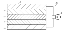
- FIG. 1 is a vertical cross-sectional view showing a schematic diagram of a basic layered structure of an embodiment of a secondary battery according to the present invention.
- the slurry for forming a positive electrode of the nonaqueous electrolyte secondary battery of the present invention is a slurry (suspension, dispersion) containing a positive electrode active material, an electrolyte, and a dispersion medium, and is a slurry suitable for forming a positive electrode active material layer of a nonaqueous electrolyte secondary battery.
- the positive electrode active material is composed of a large particle group A having a particle size of 5.0 ⁇ m or more and a small particle group B having a particle size of less than 5.0 ⁇ m, and when the total frequency in a number-based particle size distribution of the positive electrode active material is taken as 100%, the frequency of the large particle group A is 60% or more and the frequency of the small particle group B is 40% or less, and the amount of absorption of the dispersion medium by the small particle group B per 100 g, ⁇ B (g/100 g), satisfies the following formula B1: Formula B1: 15 ⁇ B ⁇ 30
- the positive electrode slurry of the present invention is composed of a positive electrode active material consisting of large particle group A and small particle group B, and the amount of dispersion medium absorbed by small particle group B is controlled within the above range. It is believed that the small particle group B, which retains a relatively large amount of dispersion medium, acts like a binder by being present in the gaps between large particle group A, effectively increasing the interaction (adhesion) between the solid particles. As a result, even if the positive electrode active material layer formed has a film thickness of about 350 ⁇ m, the formed positive electrode active material layer has excellent shape stability, and it is believed that the battery capacity of the obtained nonaqueous electrolyte secondary battery can be sufficiently increased.
- the positive electrode active material constituting the positive electrode slurry of the present invention is composed of a large particle group A having a particle size of 5.0 ⁇ m or more and a small particle group B having a particle size of less than 5.0 ⁇ m. That is, the positive electrode active material used in the present invention is roughly divided into a large particle group having a particle size including the threshold particle size of 5.0 ⁇ m and a particle group having a particle size smaller than this threshold particle size.
- the particle size can be measured using a particle size measuring device in accordance with the method for measuring particle size distribution based on number, which will be described later.
- the frequency of the large particle group A (the number of particles of the positive electrode active material classified into the large particle group A) is preferably 60 to 90%, more preferably 60 to 80%, and further preferably 65 to 75%.
- the frequency of small particle group B (the number of positive electrode active material particles classified into small particle group B) is preferably 10 to 40%, more preferably 20 to 40%, and even more preferably 25 to 35%.
- the frequency of the large particle group A and the small particle group B in the positive electrode active material can be controlled by mixing and using positive electrode active materials having different median diameters.
- the number-based particle size distribution of the positive electrode active material can be obtained by the method described in the Examples.
- the amount of dispersion medium absorbed by the small particle group B per 100 g, ⁇ B (g/100 g), satisfies the formula B1: 15 ⁇ B ⁇ 30. If the liquid absorption amount ⁇ B is too low, the interaction between the particles of the small particle group B cannot be increased to a desired level, and the formed positive electrode active material layer is prone to collapse. On the other hand, if the liquid absorption amount ⁇ B is too high, the formed positive electrode active material layer is likely to become powdery and is also prone to collapse.
- the amount of dispersion medium absorbed ⁇ B per 100 g of small particle group B means the amount of dispersion medium that 100 g of small particle group B can retain within its structure.
- the amount of dispersion medium absorbed by the small particle group B per 100 g ⁇ B can be determined as follows in accordance with JIS K6217-4:2017. -Method for measuring the amount of absorbed liquid- The liquid absorption is measured using an oil absorption measuring device (S-500 (product name), manufactured by Asahi Research Institute, Ltd.).
- the dispersion medium constituting the positive electrode slurry is added dropwise to 100 g of the powder of the positive electrode active material, the torque is measured, and the amount of dispersion medium added (mL) at which the torque becomes maximum (maximum) is measured.
- the positive electrode slurry of the present invention contains a mixed dispersion medium composed of two or more dispersion media as a dispersion medium, the above-mentioned liquid absorption amount is measured using this mixed dispersion medium as "the dispersion medium constituting the positive electrode slurry.”
- the positive electrode slurry of the present invention preferably satisfies the following formula B2, and more preferably satisfies formula B3.
- the amount of liquid absorbed by the small particle group B in the dispersion medium constituting the positive electrode slurry can be controlled by previously performing surface smoothing treatment on at least the positive electrode active material classified into the small particle group B and blending this in the positive electrode slurry.
- this surface smoothing treatment include mixing.
- the atmosphere during the surface smoothing treatment is not particularly limited, and it is preferable to perform the surface smoothing treatment under an inert gas atmosphere in order to prevent oxidation of the active material particle surface during treatment. For example, mixing under an argon atmosphere, a nitrogen atmosphere, a nitrogen-hydrogen mixed atmosphere, etc. can be mentioned.
- the treatment device in the surface smoothing treatment is not particularly limited, and examples thereof include a planetary ball mill (trade name: P-5, manufactured by Fritsch), a jet mill crusher (trade name: JETMILL100, manufactured by Powrex Corporation), a powder treatment device Nobilta (trade name: NOB MINI, manufactured by Hosokawa Micron Corporation), and a powder treatment device Composite (trade name: CP15, manufactured by Nippon Coke and Engineering Co., Ltd.).
- the treatment conditions for the above surface smoothing treatment are not particularly limited.
- mixing can be performed using a powder processing device Nobilta (product name: NOB MINI, manufactured by Hosokawa Micron Corporation) in a nitrogen atmosphere at a rotation speed of 5,000 to 9,000 rpm for a treatment time of 5 to 20 minutes.
- NOB MINI powder processing device Nobilta
- the liquid absorption amount ⁇ B decreases.
- the amount of liquid absorption ⁇ A (g/100 g) of the dispersion medium per 100 g of the large particle group A can be expressed by the following formula A0, and preferably satisfies formula A1, and more preferably satisfies formula A2.
- Formula A2: 2 ⁇ A ⁇ 7 The amount of liquid absorption ⁇ A can be measured in the same manner as the amount of liquid absorption ⁇ B.
- the amount of dispersion medium absorbed by the large particle group A, ⁇ A can be controlled within the above range by subjecting the large particle group A to a surface smoothing treatment, similar to that described for the small particle group B.
- the surface smoothing treatment is the same as that described for the small particle group B.
- the amount of dispersion medium absorption ⁇ A of the large particle group A can be calculated in the same manner as the amount of dispersion medium absorption ⁇ B of the small particle group B.
- the absolute value of the difference in the amount of liquid absorption between the large particle group A's dispersion medium absorption amount ⁇ A and the small particle group B's dispersion medium absorption amount ⁇ B (
- the closest packing rate of the positive electrode active material calculated from the cumulative particle size distribution based on volume of the positive electrode active material is preferably 75% or more, more preferably 80% or more.
- the packing rate of the positive electrode active material in the obtained positive electrode active material layer can be increased.
- This close packing ratio is an estimated value calculated based on data on the volume-based cumulative particle size distribution of the positive electrode active material contained in the positive electrode slurry of the present invention. Specifically, the closest packing ratio can be calculated by the method described in the examples of the present invention.
- the specific surface area of the small particle group B is preferably 8.0 to 13.0 m 2 /g, and more preferably 9.0 to 12.5 m 2 /g.
- the specific surface area of the large particle group A is preferably 5.0 to 8.5 m 2 /g, and more preferably 5.2 to 8.3 m 2 /g.
- the specific surface area of each of the large particle group A and the small particle group B can be measured by the BET method as described below. -BET specific surface area measurement method- 0.2 g of a sample is dried at 120° C. for 6 hours, and then measured using a BELSORP mini (product name) manufactured by Microtrac under the following measurement conditions.
- Adsorption gas N2 Equilibration time: 100 seconds
- a positive electrode active material having a large median diameter (D50) and a positive electrode active material having a small median diameter (D50) can be mixed and used as the positive electrode active material.
- the median diameter (D50) of the positive electrode active material (positive electrode active material a, large particle group a) having a large median diameter (D50) can be 6.0 to 20.0 ⁇ m, preferably 7.0 to 15.0 ⁇ m, more preferably 8.0 to 14.0 ⁇ m, and even more preferably 8.3 to 13.0 ⁇ m.
- the median diameter (D50) of the positive electrode active material (positive electrode active material b, small particle group b) having a small median diameter (D50) can be 0.1 to 4.0 ⁇ m, preferably 0.2 to 3.0 ⁇ m, more preferably 0.5 to 2.0 ⁇ m, and even more preferably 0.8 to 1.2 ⁇ m.
- a normal grinder or classifier may be used in order to make the positive electrode active material a (large particle group a) and the positive electrode active material b (small particle group b) have a predetermined median diameter (D50).
- the positive electrode active material obtained by the firing method may be used after washing with water, an acidic aqueous solution, an alkaline aqueous solution, or an organic solvent.
- the median diameter (D50) of the positive electrode active material a (large particle group a) and the positive electrode active material b (small particle group b) can be measured by the following method. -Method of measuring median diameter (D50)-
- the positive electrode active material is dispersed in water, and the particle size (volume-based median diameter D50 in water) obtained by measuring the particle size distribution using a laser diffraction/scattering particle size distribution measuring device (e.g., Particle LA-960V2 manufactured by HORIBA) is used. This also applies to the median diameter (D50) of solid particles other than the positive electrode active material.
- the positive electrode slurry of the present invention may contain the same components as a normal positive electrode slurry, except that it contains the positive electrode active material consisting of the large particle group A and the small particle group B, an electrolyte, and a dispersion medium.
- it may contain a conductive assistant, etc.
- the positive electrode active material is preferably one that can reversibly insert and release lithium ions.
- the material is not particularly limited, and examples thereof include transition metal oxides, organic substances, and substances that can be composited with Li, such as sulfur, and also include composites of sulfur and metals.
- the positive electrode active material it is preferable to use a lithium-containing transition metal oxide, and a lithium-containing transition metal oxide having a transition metal element M a (one or more elements selected from Co, Ni, Fe, Mn, Cu and V) is more preferable.
- this lithium-containing transition metal oxide may be mixed with an element M b (an element of the first (Ia) group of the periodic table other than lithium, an element of the second (IIa) group, Al, Ga, In, Ge, Sn, Pb, Sb, Bi, Si, P or B, etc.).
- the amount of the mixture is preferably 0 to 30 mol% with respect to the amount of the transition metal element M a (100 mol%). It is more preferable to mix and synthesize the Li/M a so that the molar ratio is 0.3 to 2.2.
- lithium-containing transition metal oxide examples include (MA) a lithium-containing transition metal oxide having a layered rock salt structure, (MB) a lithium-containing transition metal oxide having a spinel structure, (MC) a lithium-containing transition metal phosphate compound, (MD) a lithium-containing transition metal halide phosphate compound, and (ME) a lithium-containing transition metal silicate compound.
- MA a lithium-containing transition metal oxide having a layered rock salt structure
- MB lithium-containing transition metal oxide having a spinel structure
- MC lithium-containing transition metal phosphate compound
- MD lithium-containing transition metal halide phosphate compound
- ME lithium-containing transition metal silicate compound
- lithium - containing transition metal oxides having a layered rock salt structure include LiCoO2 (lithium cobalt oxide [LCO]), LiNi2O2 (lithium nickel oxide ) , LiNi0.85Co0.10Al0.05O2 (lithium nickel cobalt aluminum oxide [NCA]), LiNi1 /3Co1 / 3Mn1 / 3O2 (lithium nickel manganese cobalt oxide [NMC]), and LiNi0.5Mn0.5O2 (lithium manganese nickel oxide ) .
- LiCoO2 lithium cobalt oxide [LCO]
- LiNi2O2 lithium nickel oxide
- LiNi0.85Co0.10Al0.05O2 lithium nickel cobalt aluminum oxide [NCA]
- LiNi1 /3Co1 / 3Mn1 / 3O2 lithium nickel manganese cobalt oxide [NMC]
- LiNi0.5Mn0.5O2 lithium manganese nickel oxide
- lithium - containing transition metal oxides having a spinel structure examples include LiMn2O4 ( LMO ) , LiCoMnO4 , Li2FeMn3O8 , Li2CuMn3O8 , Li2CrMn3O8 , and Li2NiMn3O8 .
- lithium-containing transition metal phosphate compounds include olivine-type iron phosphates such as LiFePO4 and Li3Fe2 ( PO4 ) 3 , iron pyrophosphates such as LiFeP2O7 , cobalt phosphates such as LiCoPO4 , and monoclinic Nasicon-type vanadium phosphates such as Li3V2 ( PO4 ) 3 (lithium vanadium phosphate).
- the lithium-containing transition metal halophosphate compound include iron fluorophosphates such as Li 2 FePO 4 F, manganese fluorophosphates such as Li 2 MnPO 4 F, and cobalt fluorophosphates such as Li 2 CoPO 4 F.
- the positive electrode active material is preferably a lithium-containing transition metal oxide having a layered rock salt structure (MA) and a lithium-containing transition metal phosphate compound (MC), more preferably LiNi1 / 3Co1 / 3Mn1/ 3O2 and LiFePO4 , and even more preferably LiFePO4 .
- MA layered rock salt structure
- MC lithium-containing transition metal phosphate compound
- the chemical formula of the compound obtained by the above calcination method can be measured using inductively coupled plasma (ICP) emission spectroscopy, or simply calculated from the mass difference of the powder before and after calcination.
- ICP inductively coupled plasma
- the surface of the positive electrode active material may be coated with an oxide such as another metal oxide, a carbon-based material, etc. These surface coating layers can function as an interface resistance stabilizing layer.
- Surface coating materials include metal oxides containing Ti, Nb, Ta, W, Zr, Al, Si, or Li.
- the oxides include titanate spinel, tantalum-based oxides, niobium -based oxides, and lithium niobate -based compounds, such as Li4Ti5O12 , Li2Ti2O5 , LiTaO3 , LiNbO3 , LiAlO2 , Li2ZrO3, Li2WO4 , Li2TiO3 , Li2B4O7, Li3PO4 , Li2MoO4 , Li3BO3 , LiBO2 , Li2CO3 , Li2SiO3 , SiO2 , TiO2 , ZrO2 , Al2O3 , B2O3 , and Li3 AlF6 .
- Carbon-based materials such as C, SiC, and SiOC (carbon-doped silicon oxide) can also be used as the surface coating material.
- the positive electrode active material is preferably surface-coated with a carbon-based material in order to increase the electronic conductivity to a desired level.
- the positive electrode active material is preferably surface-coated with carbon (C).
- the carbon surface coating can be formed by baking the positive electrode active material in the presence of an additive (organic substance) that serves as a carbon source. Examples of additives that can be used include styrene-maleic anhydride copolymer, polystyrene, polycarbonate, etc.
- the surface of the positive electrode active material may be treated with sulfur or phosphorus. Furthermore, the particle surfaces of the positive electrode active material may be subjected to a surface treatment with active rays or active gas (plasma, etc.) before or after the above-mentioned surface coating.
- the above positive electrode active materials may be used alone or in combination of two or more.
- the content of the positive electrode active material in the total content of the positive electrode active material and the conductive assistant in the positive electrode slurry is preferably 96.00 to 99.97 mass%, more preferably 98.00 to 99.97 mass%, even more preferably 99.00 to 99.95 mass%, even more preferably 99.20 to 99.90 mass%, even more preferably 99.50 to 99.80 mass%, even more preferably 99.55 to 99.80 mass%, and even more preferably 99.60 to 99.80 mass%.
- the positive electrode slurry of the present invention may contain a conductive assistant.
- the conductive assistant may be any of those known as general conductive assistants.
- it may be an electron conductive material such as graphites, such as natural graphite and artificial graphite, carbon blacks, such as acetylene black, ketjen black, and furnace black, amorphous carbon, such as needle coke, carbon fibers, such as vapor-grown carbon fibers and carbon nanotubes, carbonaceous materials, such as graphene and fullerene, metal powders, metal fibers, such as copper and nickel, or conductive polymers, such as polyaniline, polypyrrole, polythiophene, polyacetylene, and polyphenylene derivatives.
- the conductive assistant is preferably a carbonaceous material, more preferably carbon blacks, and more preferably ketjen black.
- the positive electrode active material and the conductive assistant among the above conductive assistants, those that do not insert or release Li when the battery is charged and discharged and do not function as an active material are considered to be conductive assistants. Therefore, among the conductive assistants, those that can function as an active material in the active material layer when the battery is charged and discharged are classified as active materials rather than conductive assistants. Whether or not they function as an active material when the battery is charged and discharged is not unique, but is determined by the combination with the active material.
- the shape of the conductive assistant is not particularly limited, but a particulate shape is preferred.
- the median diameter (D50) of the conductive assistant is not particularly limited and is, for example, preferably 0.01 to 50 ⁇ m, more preferably 0.1 to 10 ⁇ m, and further preferably 0.2 to 2.0 ⁇ m.
- the conductive assistant may be surface-treated.
- the method of surface treatment is not particularly limited, and surface treatment using a chemical treating agent and atomic layer deposition (ALD) treatment are preferred.
- ALD atomic layer deposition
- an organic silicon compound more preferably, a silane coupling agent
- an organic phosphonic acid compound and the like are preferable, and examples thereof include methyltrimethoxysilane (MTMS), octadecyltrimethoxysilane, hexamethyldisilazane, tetraethoxysilane, trifluoropropyltrimethoxysilane, vinyltrimethoxysilane, phenyltrimethoxysilane, 3-aminopropyltriethoxysilane, 1H,1H,2H,2H-perfluorooctyltriethoxysilane, trimethoxy(octyl)silane, 1H,1H,2H,2H-perfluor
- the content of the conductive assistant in the total content of the positive electrode active material and the conductive assistant in the positive electrode slurry is preferably 0.03 to 4.00 mass%, more preferably 0.03 to 2.00 mass%, even more preferably 0.05 to 1.00 mass%, even more preferably 0.10 to 0.80 mass%, even more preferably 0.20 to 0.50 mass%, even more preferably 0.20 to 0.45 mass%, and even more preferably 0.20 to 0.40 mass%.
- the electrolyte may be any electrolyte used in electrolytic solutions for quasi-solid secondary batteries.
- Metal salts are preferred, including lithium salts, potassium salts, sodium salts, calcium salts, and magnesium salts.
- lithium salts lithium salts that are usually used as electrolytes for lithium ion secondary batteries are preferable, and examples thereof include the following lithium salts.
- Inorganic lithium salts inorganic fluoride salts such as LiPF 6 , LiBF 4 , LiAsF 6 , and LiSbF 6 , perhalogenates such as LiClO 4 , LiBrO 4 , and LiIO 4 , and inorganic chloride salts such as LiAlCl 4 , etc.
- Oxalatoborate salts lithium bis(oxalato)borate, lithium difluorooxalatoborate, etc.
- LiPF 6 , LiBF 4 , LiAsF 6 , LiSbF 6 , LiClO 4 , Li ( Rf1SO3 ), LiN( Rf1SO2 ) 2 , LiN( FSO2 ) 2 , or LiN (Rf1SO2)(Rf2SO2) are preferred, LiPF 6 , LiBF 4 , LiN(Rf1SO2)2, LiN(FSO2)2 , or LiN ( Rf1SO2 ) ( Rf2SO2 ) are more preferred , and LiPF 6 is particularly preferred.
- Rf1 and Rf2 each represent a perfluoroalkyl group, preferably having 1 to 6 carbon atoms.
- the lithium salts used in the electrolyte solution of the present invention may be used alone or in any combination of two or more kinds.
- an electrolyte solution by adding the above electrolyte to a dispersion medium, and to prepare a positive electrode slurry using this electrolyte solution.
- concentration of the lithium salt in the electrolyte solution is usually 10.0 to 50.0 mass%, and preferably 15.0 to 30.0 mass%.
- the molar concentration is preferably 0.5 to 1.5 M.
- the dispersion medium used is a non-aqueous solvent.
- an aprotic organic solvent is preferable, and among them, an aprotic organic solvent having 2 to 10 carbon atoms is more preferable.
- non-aqueous solvents include linear or cyclic carbonate compounds, lactone compounds, linear or cyclic ether compounds, ester compounds, nitrile compounds, amide compounds, oxazolidinone compounds, nitro compounds, linear or cyclic sulfone or sulfoxide compounds, and phosphate ester compounds.
- compounds having an ether bond, a carbonyl bond, an ester bond or a carbonate bond are preferred. These compounds may have a substituent.
- non-aqueous solvents examples include ethylene carbonate, fluorinated ethylene carbonate, vinylene carbonate, propylene carbonate, butylene carbonate, dimethyl carbonate, diethyl carbonate, ethyl methyl carbonate, methyl propyl carbonate, ⁇ -butyrolactone, ⁇ -valerolactone, 1,2-dimethoxyethane, tetrahydrofuran, 2-methyltetrahydrofuran, tetrahydropyran, 1,3-dioxolane, 4-methyl-1,3-dioxolane, 1,3-dioxane, 1,4-dioxane, and methyl acetate.
- ethyl acetate methyl propionate, ethyl propionate, methyl butyrate, methyl isobutyrate, methyl trimethylacetate, ethyl trimethylacetate, acetonitrile, glutaronitrile, adiponitrile, methoxyacetonitrile, 3-methoxypropionitrile, N,N-dimethylformamide, N-methylpyrrolidone (NMP), N-methyloxazolidinone, N,N'-dimethylimidazolidinone, nitromethane, nitroethane, sulfolane, trimethyl phosphate, dimethyl sulfoxide, dimethyl sulfoxide phosphate, etc.
- the dispersion medium is preferably a mixed solvent of ethylene carbonate (EC), propylene carbonate (PC) and dimethyl carbonate (DMC).
- EC ethylene carbonate
- PC propylene carbonate
- DMC dimethyl carbonate
- the positive electrode slurry of the present invention does not contain a binder.
- the binder here refers to a binder used in general non-aqueous electrolyte secondary batteries, and examples of such binders include thermoplastic resins such as fluororesins (polytetrafluoroethylene (PTFE), polyvinylidene fluoride (PVDF), etc.), polyethylene, polypropylene, polyacrylic, and polyimide; elastomers such as ethylene-propylene-diene rubber (EPDM), sulfonated EPDM, styrene butadiene rubber (SBR), and fluororubber; polysaccharide polymers, etc.
- PTFE polytetrafluoroethylene
- PVDF polyvinylidene fluoride
- EPDM ethylene-propylene-diene rubber
- SBR styrene butadiene rubber
- fluororubber polysaccharide polymers, etc.
- the positive electrode slurry of the present invention preferably has a solids content (components other than the dispersion medium (solvent)) in the positive electrode slurry of more than 60 mass%, more preferably 65 mass% or more, and even more preferably 70 mass% or more.
- the solids content is preferably 60 to 95 mass%, more preferably 65 to 92 mass%, even more preferably 70 to 90 mass%, even more preferably 72 to 88 mass%, and particularly preferably 75 to 85 mass%.
- the positive electrode slurry of the present invention may contain, as desired, an ionic liquid, a thickener, an antifoaming agent, a leveling agent, a dehydrating agent, an antioxidant, etc. These may be any of those commonly used in non-aqueous electrolyte secondary batteries.
- the content of the other components is preferably 0.05 to 1.5 parts by mass, and more preferably 0.1 to 1.0 part by mass, per 100 parts by mass of the total content of the positive electrode active material and the conductive assistant.
- the positive electrode slurry of the present invention can be prepared by mixing the positive electrode active material consisting of the large particle group A and the small particle group B, the electrolyte, the dispersion medium, and any other optional components, for example, in any of various commonly used mixers.
- the positive electrode sheet of the present invention is a positive electrode sheet having a positive electrode active material layer formed using the positive electrode slurry of the present invention, and is a positive electrode sheet suitable as a positive electrode sheet for a non-aqueous electrolyte secondary battery.
- the positive electrode active material layer contains a positive electrode active material composed of a large particle group A having a particle size of 5.0 ⁇ m or more and a small particle group B having a particle size of less than 5.0 ⁇ m, and when the total frequency in the number-based particle size distribution of the positive electrode active material is taken as 100%, the frequency of the large particle group A is 60% or more and the frequency of the small particle group B is 40% or less, and the amount of dispersion medium absorbed by the small particle group B per 100 g, ⁇ B (g/100 g), satisfies the above formula B1.
- the term "positive electrode sheet” includes both an embodiment in which the sheet is incorporated as a component of a nonaqueous electrolyte secondary battery (in a state in which the sheet is incorporated in a secondary battery) and an embodiment in which the sheet is a positive electrode material before being incorporated in a nonaqueous electrolyte secondary battery.
- the structure (area, thickness, etc.) of the positive electrode sheet may be a structure used as a positive electrode or a structure that can be processed into a structure used as a positive electrode.
- the positive electrode sheet of the present invention may have a positive electrode active material layer formed using the positive electrode slurry of the present invention, and may be in a form in which the positive electrode active material layer and the positive electrode current collector are laminated. More specifically, the positive electrode active material layer may be laminated on both sides of the positive electrode current collector, or the positive electrode active material layer may be laminated on one side of the positive electrode current collector.
- the positive electrode sheet is usually a sheet having a configuration in which the positive electrode active material layer is laminated on the positive electrode current collector.
- the positive electrode active material layer may be composed of a single layer or multiple layers.
- the positive electrode sheet may further have other layers as necessary. Examples of the other layers include a protective layer (release sheet) and a coating layer.
- the positive electrode active material layer is preferably laminated in a state of being in direct contact with the positive electrode current collector.
- the thickness of the positive electrode active material layer is not particularly limited and can be, for example, 50 to 600 ⁇ m, preferably 150 to 500 ⁇ m, and more preferably 200 to 400 ⁇ m.
- the positive electrode current collector constituting the positive electrode sheet of the present invention is not particularly limited, and a positive electrode current collector used in a normal secondary battery can be appropriately applied.
- a positive electrode current collector used in a normal secondary battery for example, JP 2016-201308 A, JP 2005-108835 A, JP 2012-185938 A, WO 2018/135395, etc. can be appropriately referred to.
- the positive electrode current collector is preferably made of aluminum, an aluminum alloy, or the like.
- the positive electrode sheet of the present invention is less susceptible to collapse (peeling) of the positive electrode active material layer. Usually, this collapse is most noticeable at the ends of the positive electrode active material layer.
- the positive electrode sheet of the present invention can be obtained by forming a positive electrode active material layer using the positive electrode slurry of the present invention.
- the positive electrode sheet of the present invention can be obtained by forming a film using the positive electrode slurry of the present invention. More specifically, a positive electrode current collector or the like is used as a substrate, and the positive electrode slurry of the present invention is applied thereon (although other layers may be interposed) to obtain a positive electrode sheet having a positive electrode active material layer on the substrate.
- the method for applying the positive electrode slurry is not particularly limited, and can be, for example, application using a roll coater, drop coating, placing the positive electrode slurry evenly on a positive electrode current collector or the like and then pressing (roll press or flat plate press), or placing the positive electrode slurry within a frame of a specified thickness and spreading it out.
- the nonaqueous electrolyte secondary battery of the present invention (hereinafter also referred to as the "secondary battery of the present invention") has the positive electrode sheet of the present invention as a positive electrode.
- the battery may have the same structure as a normal non-aqueous electrolyte secondary battery. That is, the secondary battery of the present invention can be obtained by incorporating the positive electrode sheet of the present invention into the positive electrode of a normal non-aqueous electrolyte secondary battery.
- FIG. 1 is a cross-sectional view showing a typical laminated structure of a nonaqueous electrolyte secondary battery 10, including the operating portion when the battery is operated.
- the nonaqueous electrolyte secondary battery 10 has a laminated structure having, in this order, a negative electrode collector 1, a negative electrode active material layer 2, a separator 3, a positive electrode active material layer 4, and a positive electrode collector 5, as seen from the negative electrode side.
- the negative electrode active material layer 2 and the positive electrode active material layer 4 are filled with a nonaqueous electrolyte (not shown) and are separated by the separator 3.
- the separator 3 has pores, and in a normal battery use state, it functions as a separator membrane for the positive and negative electrodes that insulates between the positive and negative electrodes while allowing the electrolyte and ions to pass through the pores.
- a lithium ion secondary battery electrons (e ⁇ ) are supplied to the negative electrode side through an external circuit during charging, and at the same time, lithium ions (Li + ) move from the positive electrode through the electrolyte and are accumulated in the negative electrode.
- the lithium ions (Li + ) stored in the negative electrode are returned to the positive electrode side through the electrolyte, and electrons are supplied to the operating part 6.
- a light bulb is used as the operating part 6, and this is turned on by discharging.
- the electrode active material layer of the quasi-solid secondary battery is formed in a slurry state containing the electrode active material and the electrolyte. Therefore, the electrode active material layer is a layer using a slurry (suspension, dispersion) in which the electrode active material is dispersed in a non-aqueous electrolyte, and thus the structure of the quasi-solid secondary battery is different from that of a general non-aqueous electrolyte secondary battery.
- a coating solution is prepared by dispersing an electrode active material in a medium that does not contain an electrolyte, and the coating solution is applied to a current collector to form a coating film, and the coating film is dried to form a thin-film electrode active material layer.
- a binder is usually blended into the coating solution, and a hard electrode active material layer in which the electrode active material particles are firmly bound to each other is formed.
- the electrode active material layer is in the state of a hard solid particle layer as a whole, and is not a slurry layer.
- the electrode active material layer is an electrode slurry layer formed by dispersing solid particles containing an electrode active material and a conductive assistant in a non-aqueous electrolyte solution formed by dissolving a lithium salt (electrolyte) in a non-aqueous solvent.
- the electrode slurry layer functions as an electrode active material layer, strong binding between the electrode active material particles is not required, and therefore the electrode slurry layer usually does not contain a binder. Except for the fact that the electrode active material layer is an electrode slurry layer and that the electrode slurry layer is in contact with the separator, the basic layer structure of the quasi-solid secondary battery is the same as the layer structure shown in FIG.
- the secondary battery of the present invention is the above-mentioned quasi-solid secondary battery, in which the positive electrode active material layer is a slurry layer formed from the positive electrode slurry of the present invention.
- the negative electrode active material layer a negative electrode active material layer formed from a normal negative electrode slurry can be used.
- the materials and components such as the negative electrode active material, the negative electrode current collector, and the separator are not particularly limited. These materials and components can be appropriately applied from those used in ordinary secondary batteries.
- the components and manufacturing methods usually used in these secondary batteries reference can be made, for example, to JP 2016-201308 A, JP 2005-108835 A, JP 2012-185938 A, WO 2018/135395, etc.
- a normal method can be appropriately adopted, except that the positive electrode sheet of the present invention is used as the positive electrode.
- JP-A-2016-201308, JP-A-2005-108835, JP-A-2012-185938, JP-A-2017-147222, etc. can be appropriately referred to.
- the nonaqueous electrolyte secondary battery of the present invention can be installed in electronic devices such as notebook computers, pen-input computers, mobile computers, electronic book players, mobile phones, cordless phone handsets, pagers, handheld terminals, mobile fax machines, mobile copiers, mobile printers, headphone stereos, video movie machines, liquid crystal televisions, handheld cleaners, portable CDs, mini-discs, electric shavers, transceivers, electronic organizers, calculators, memory cards, portable tape recorders, radios, backup power supplies, and memory cards. It can also be installed in consumer devices such as automobiles, electric vehicles, motors, lighting equipment, toys, game equipment, road conditioners, watches, strobes, cameras, and medical equipment (pacemakers, hearing aids, shoulder massagers, etc.). It can also be used for various military and space applications. It can also be combined with solar cells.
- electronic devices such as notebook computers, pen-input computers, mobile computers, electronic book players, mobile phones, cordless phone handsets, pagers, handheld terminals, mobile
- the positive electrode active material was prepared as follows.
- LFP1-1 to LFP1-3 (large particle group a)>
- LFP1-1 An LFP (LiFePO 4 ) powder raw material (manufactured by LOPAL, P198-S13 (product name)) was used.
- LFP1-2 and LFP1-3 20 g of LFP1-1 was put into a powder processing device Nobilta (product name: NOB MINI, manufactured by Hosokawa Micron Corporation), and surface smoothing treatment was performed in a nitrogen atmosphere at the rotation speed and treatment time shown in Table 1. As a result, positive electrode active materials LFP1-2 and LFP1-3 in the form of powder were obtained, respectively.
- LFP2-1 to LFP2-6 small particle group b>
- An LFP (LiFePO 4 ) powder raw material P198-T5 (product name) manufactured by LOPAL) was used.
- LFP2-2 to LFP2-6) 20 g of LFP2-1 was put into a powder processing device Nobilta (product name: NOB MINI, manufactured by Hosokawa Micron Corporation), and surface smoothing treatment was performed in a nitrogen atmosphere at the rotation speed and treatment time shown in Table 1. As a result, positive electrode active materials LFP2-2 to LFP2-6 having the shape of a powder were obtained, respectively.
- NMC1-1 to NMC1-3 (large particle group a)>
- NMC1-1 An NMC (LiNi 1/3 Co 1/3 Mn 1/3 O 2 ) powder raw material (manufactured by Toshima Manufacturing Co., Ltd., NCM111 (particle size 12 ⁇ m) (product name)) was used.
- NMC1-2 and NMC1-3 20 g of NMC1-1 was put into a powder processing device Nobilta (product name: NOB MINI, manufactured by Hosokawa Micron Corporation), and surface smoothing treatment was performed in a nitrogen atmosphere at the rotation speed and treatment time shown in Table 1. As a result, positive electrode active materials NMC1-2 and NMC1-3 in the shape of a powder were obtained, respectively.
- NMC2-1 to NMC2-6 small particle group b>
- NMC2-1 An NMC (LiNi 1/3 Co 1/3 Mn 1/3 O 2 ) powder raw material (manufactured by Toshima Manufacturing Co., Ltd., NCM111 (particle size 2 ⁇ m) (product name)) was used.
- NMC2-2 to NMC2-6) 20 g of NMC2-1 was put into a powder processing device Nobilta (product name: NOB MINI, manufactured by Hosokawa Micron Corporation), and surface smoothing treatment was performed in a nitrogen atmosphere at the rotation speed and treatment time shown in Table 1. As a result, positive electrode active materials NMC2-2 to NMC2-6 having the shape of a powder were obtained, respectively.
- the number-based particle size distributions of LFP1-1 to LFP1-3 and NMC1-1 to NMC1-3 were obtained as described below, and each of the positive electrode active materials contained substantially no particles with a particle size of less than 5.0 ⁇ m.
- the number-based particle size distributions of LFP2-1 to LFP2-6 and NMC2-1 to NMC2-6 were obtained as described below, and each of the positive electrode active materials contained substantially no particles with a particle size of 5.0 ⁇ m or more.
- EC ethylene carbonate
- PC propylene carbonate
- DMC dimethyl carbonate
- slurry for forming positive electrode 75 parts by mass of a positive electrode active material containing the large particle group A and the small particle group B shown in Table 2 in the ratio shown in Table 2, 0.3 parts by mass of Ketjen black (Carbon ECP600JD (trade name), manufactured by Lion) as a conductive assistant, and 24.7 parts by mass of nonaqueous electrolyte I were mixed at 1250 rpm for 90 seconds in a centrifugal planetary mixer (Thinky Corporation: Awatori Rentaro ARE-310 (trade name)) to obtain a positive electrode forming slurry (No. 1 to 24).
- the positive electrode active material used in the preparation of the positive electrode forming slurries of Experiments No. 2 to 4, 6 to 12, 14 to 16, and 18 to 24 was a mixture of the large particle group a and the small particle group b, and the large particle group A and the small particle group B were mixed to have the number frequency shown in Table 2.
- Each of the positive electrode forming slurries obtained above was applied to one side of a positive electrode current collector (aluminum foil) having a thickness of 12 ⁇ m to obtain a positive electrode sheet consisting of the positive electrode current collector and a positive electrode active material layer (slurry layer).
- the thickness of the positive electrode active material layer of this positive electrode sheet was 350 ⁇ m.
- a negative electrode sheet was prepared by mixing 65 parts by mass of a negative electrode active material (artificial graphite, UF-G30, manufactured by Showa Denko Kogyo Co., Ltd.) and 1 part by mass of acetylene black (Li-100 (trade name), manufactured by Denka Co., Ltd.) as a conductive assistant. 34 parts by mass of nonaqueous electrolyte I was mixed in a centrifugal planetary mixer (Thinky Corporation: Awatori Rentaro (product name)) at 1250 rpm for 90 seconds to obtain a negative electrode forming slurry.
- a centrifugal planetary mixer Thinky Corporation: Awatori Rentaro (product name)
- the obtained negative electrode forming slurry was applied to one side of a negative electrode current collector (copper foil) having a thickness of 12 ⁇ m to obtain a negative electrode sheet consisting of the negative electrode current collector and a negative electrode active material layer (slurry layer).
- the thickness of the negative electrode active material layer of the sheet was about 300 ⁇ m.
- 2) Preparation of a non-aqueous electrolyte secondary battery A separator was placed on the negative electrode sheet obtained above, and then the positive electrode sheet obtained in the above [Preparation of the positive electrode sheet] was placed on top of the negative electrode current collector-negative electrode active material layer.
- the laminate was made of the positive electrode active material layer (slurry layer)-separator-positive electrode active material layer (slurry layer)-positive electrode current collector.
- An aluminum tab was attached to the end of the aluminum current collector of this laminate, and a nickel tab was attached to the end of the copper current collector.
- the tabs were attached by ultrasonic welding to form an electrode group.
- the electrode group was sandwiched between two aluminum laminate films, three sides were heat sealed, and the remaining side was vacuum sealed to form a laminated non-contact electrode.
- An aqueous electrolyte secondary battery (quasi-solid secondary battery) was fabricated.
- Each of the positive electrode-forming slurries obtained above was applied to one side of a 12 ⁇ m-thick positive electrode current collector (aluminum foil) to a width of 5 cm, a length of 8 cm and a thickness of 350 ⁇ m, to obtain a positive electrode sheet consisting of the positive electrode current collector and a positive electrode active material layer (slurry layer).
- the center of each positive electrode sheet obtained above was punched out with a 2.5 cm square punching machine (manufactured by Nogami Giken Co., Ltd., clearance 1 ⁇ m), and the entire amount of the collapsed (peeled off) material that fell during the punching was collected and weighed.
- the positive electrode sheet used in the preparation of each of the nonaqueous electrolyte secondary batteries was punched out to a diameter of 10 mm, the positive electrode current collector was removed from the punched piece, and the thickness of the positive electrode active material layer was measured.
- the thickness of the negative electrode active material layer was measured in the same manner.
- the thickness of the power generating element was calculated by the thickness of the positive electrode current collector + the thickness of the positive electrode active material layer + the thickness of the separator + the thickness of the negative electrode active material layer + the thickness of the negative electrode current collector.
- the thickness of each constituent layer was measured using a constant pressure thickness measuring device (product name: PG-20J, manufactured by Techlock Corporation).
- the volume (L) of the power generating element was calculated by multiplying the thickness of the power generating element by the area of the circular surface of the power generating element.
- the ideal volume of the power generating element was calculated without taking into account the volume reduction due to the collapse of the end due to punching of the positive electrode sheet, etc.
- the volumetric energy density of the nonaqueous electrolyte secondary battery was calculated by dividing the amount of power (Wh) thus obtained by the volume (L) of the power generating element obtained above.
- the obtained value was evaluated according to the following evaluation criteria.
- Charge/discharge conditions> Charge and discharge conditions for Experiments No.
- Constant current (CC)-constant voltage (CV) charging current value 15mA, upper limit voltage value 3.6V, final current value 0.5mA CC discharge: current value 15mA, final voltage value 2.0V (Charge and discharge conditions for Experiments No. 13 to 24 (Experiments using NMC as the positive electrode active material))
- CC-CV charging current value 15mA, upper limit voltage value 4.2V, final current value 0.5mA CC discharge: current value 15mA, upper limit voltage value 3.0V
- the positive electrode forming slurry contains the large particle group A and the small particle group B at the frequency specified in the present invention, and the amount of the dispersion medium absorbed by the small particle group B satisfies the formula B1: 15 ⁇ B ⁇ 30 (Experiment Nos. 2, 3, 6 to 10, 14, 15, 18 to 22), even if a positive electrode active material layer having a thickness of 350 ⁇ m is formed, the end portion of the positive electrode active material in the obtained positive electrode sheet is prevented from collapsing, resulting in excellent shape stability. Furthermore, the battery capacity of a nonaqueous electrolyte secondary battery having this positive electrode sheet as a positive electrode was also improved.
- Non-aqueous electrolyte secondary battery 1 Negative electrode current collector 2 Negative electrode active material layer 3 Separator 4 Positive electrode active material layer 5 Positive electrode current collector 6 Working part (light bulb)
Landscapes
- Chemical & Material Sciences (AREA)
- Chemical Kinetics & Catalysis (AREA)
- Electrochemistry (AREA)
- General Chemical & Material Sciences (AREA)
- Composite Materials (AREA)
- Inorganic Chemistry (AREA)
- Engineering & Computer Science (AREA)
- Crystallography & Structural Chemistry (AREA)
- Manufacturing & Machinery (AREA)
- Materials Engineering (AREA)
- Battery Electrode And Active Subsutance (AREA)
Priority Applications (4)
| Application Number | Priority Date | Filing Date | Title |
|---|---|---|---|
| EP24815336.3A EP4723206A1 (en) | 2023-05-31 | 2024-05-22 | Slurry for forming positive electrode of non-aqueous electrolyte secondary battery, positive electrode sheet, and non-aqueous electrolyte secondary battery |
| CN202480029353.6A CN121039833A (zh) | 2023-05-31 | 2024-05-22 | 非水电解液二次电池的正极形成用浆料、正极片及非水电解液二次电池 |
| JP2025524025A JPWO2024247852A1 (https=) | 2023-05-31 | 2024-05-22 | |
| US19/378,250 US20260058128A1 (en) | 2023-05-31 | 2025-11-03 | Slurry for forming positive electrode of non-aqueous electrolytic solution secondary battery, positive electrode sheet, and non-aqueous electrolytic solution secondary battery |
Applications Claiming Priority (2)
| Application Number | Priority Date | Filing Date | Title |
|---|---|---|---|
| JP2023090455 | 2023-05-31 | ||
| JP2023-090455 | 2023-05-31 |
Related Child Applications (1)
| Application Number | Title | Priority Date | Filing Date |
|---|---|---|---|
| US19/378,250 Continuation US20260058128A1 (en) | 2023-05-31 | 2025-11-03 | Slurry for forming positive electrode of non-aqueous electrolytic solution secondary battery, positive electrode sheet, and non-aqueous electrolytic solution secondary battery |
Publications (1)
| Publication Number | Publication Date |
|---|---|
| WO2024247852A1 true WO2024247852A1 (ja) | 2024-12-05 |
Family
ID=93657828
Family Applications (1)
| Application Number | Title | Priority Date | Filing Date |
|---|---|---|---|
| PCT/JP2024/018888 Ceased WO2024247852A1 (ja) | 2023-05-31 | 2024-05-22 | 非水電解液二次電池の正極形成用スラリー、正極シート、及び非水電解液二次電池 |
Country Status (5)
| Country | Link |
|---|---|
| US (1) | US20260058128A1 (https=) |
| EP (1) | EP4723206A1 (https=) |
| JP (1) | JPWO2024247852A1 (https=) |
| CN (1) | CN121039833A (https=) |
| WO (1) | WO2024247852A1 (https=) |
Citations (12)
| Publication number | Priority date | Publication date | Assignee | Title |
|---|---|---|---|---|
| JP2005108835A (ja) | 2003-09-26 | 2005-04-21 | Samsung Sdi Co Ltd | リチウムイオン二次電池 |
| JP2012185938A (ja) | 2011-03-03 | 2012-09-27 | Sharp Corp | 非水系二次電池 |
| JP2015230748A (ja) | 2014-06-03 | 2015-12-21 | トヨタ自動車株式会社 | リチウムイオン二次電池用電極の製造方法 |
| JP2016201308A (ja) | 2015-04-13 | 2016-12-01 | 富士フイルム株式会社 | 非水電解液および非水二次電池 |
| JP2017147222A (ja) | 2016-02-12 | 2017-08-24 | 三洋化成工業株式会社 | リチウムイオン電池 |
| WO2018135395A1 (ja) | 2017-01-20 | 2018-07-26 | 富士フイルム株式会社 | 非水二次電池用電解液、非水二次電池及び金属錯体 |
| WO2018155314A1 (ja) | 2017-02-24 | 2018-08-30 | 株式会社Gsユアサ | 非水電解質蓄電素子及びその製造方法 |
| JP2019029212A (ja) | 2017-07-31 | 2019-02-21 | トヨタ自動車株式会社 | リチウムイオン二次電池およびその製造方法 |
| JP2022120400A (ja) * | 2021-02-05 | 2022-08-18 | プライムプラネットエナジー&ソリューションズ株式会社 | 非水電解質二次電池 |
| JP2023034700A (ja) | 2021-08-31 | 2023-03-13 | プライムプラネットエナジー&ソリューションズ株式会社 | 正極活物質およびこれを含む非水電解質二次電池 |
| JP2023034701A (ja) * | 2021-08-31 | 2023-03-13 | プライムプラネットエナジー&ソリューションズ株式会社 | 正極活物質およびこれを含む非水電解質二次電池 |
| JP2023090455A (ja) | 2021-12-17 | 2023-06-29 | 和芳 小川 | 色消しレンズ |
-
2024
- 2024-05-22 EP EP24815336.3A patent/EP4723206A1/en active Pending
- 2024-05-22 JP JP2025524025A patent/JPWO2024247852A1/ja active Pending
- 2024-05-22 WO PCT/JP2024/018888 patent/WO2024247852A1/ja not_active Ceased
- 2024-05-22 CN CN202480029353.6A patent/CN121039833A/zh active Pending
-
2025
- 2025-11-03 US US19/378,250 patent/US20260058128A1/en active Pending
Patent Citations (12)
| Publication number | Priority date | Publication date | Assignee | Title |
|---|---|---|---|---|
| JP2005108835A (ja) | 2003-09-26 | 2005-04-21 | Samsung Sdi Co Ltd | リチウムイオン二次電池 |
| JP2012185938A (ja) | 2011-03-03 | 2012-09-27 | Sharp Corp | 非水系二次電池 |
| JP2015230748A (ja) | 2014-06-03 | 2015-12-21 | トヨタ自動車株式会社 | リチウムイオン二次電池用電極の製造方法 |
| JP2016201308A (ja) | 2015-04-13 | 2016-12-01 | 富士フイルム株式会社 | 非水電解液および非水二次電池 |
| JP2017147222A (ja) | 2016-02-12 | 2017-08-24 | 三洋化成工業株式会社 | リチウムイオン電池 |
| WO2018135395A1 (ja) | 2017-01-20 | 2018-07-26 | 富士フイルム株式会社 | 非水二次電池用電解液、非水二次電池及び金属錯体 |
| WO2018155314A1 (ja) | 2017-02-24 | 2018-08-30 | 株式会社Gsユアサ | 非水電解質蓄電素子及びその製造方法 |
| JP2019029212A (ja) | 2017-07-31 | 2019-02-21 | トヨタ自動車株式会社 | リチウムイオン二次電池およびその製造方法 |
| JP2022120400A (ja) * | 2021-02-05 | 2022-08-18 | プライムプラネットエナジー&ソリューションズ株式会社 | 非水電解質二次電池 |
| JP2023034700A (ja) | 2021-08-31 | 2023-03-13 | プライムプラネットエナジー&ソリューションズ株式会社 | 正極活物質およびこれを含む非水電解質二次電池 |
| JP2023034701A (ja) * | 2021-08-31 | 2023-03-13 | プライムプラネットエナジー&ソリューションズ株式会社 | 正極活物質およびこれを含む非水電解質二次電池 |
| JP2023090455A (ja) | 2021-12-17 | 2023-06-29 | 和芳 小川 | 色消しレンズ |
Non-Patent Citations (1)
| Title |
|---|
| See also references of EP4723206A1 |
Also Published As
| Publication number | Publication date |
|---|---|
| US20260058128A1 (en) | 2026-02-26 |
| CN121039833A (zh) | 2025-11-28 |
| JPWO2024247852A1 (https=) | 2024-12-05 |
| EP4723206A1 (en) | 2026-04-08 |
Similar Documents
| Publication | Publication Date | Title |
|---|---|---|
| JP4595987B2 (ja) | 正極活物質 | |
| US20150194664A1 (en) | Non-aqueous electrolyte secondary battery | |
| WO2017209233A1 (ja) | 固体電解質組成物、固体電解質含有シート、全固体二次電池用電極シートおよび全固体二次電池ならびに固体電解質含有シート、全固体二次電池用電極シートおよび全固体二次電池の製造方法 | |
| WO2017047280A1 (ja) | リチウム二次電池及びその製造方法 | |
| JP7040460B2 (ja) | リチウムイオン二次電池用黒鉛系材料の製造方法、リチウムイオン二次電池用負極の製造方法、及びリチウムイオン二次電池の製造方法 | |
| EP3451437B1 (en) | Lithium ion secondary cell charging method, lithium ion secondary cell system, and power storage device | |
| CN101794909A (zh) | 非水电解质二次电池 | |
| JP2007317534A (ja) | 非水電解質二次電池 | |
| WO2011117992A1 (ja) | 電池用活物質および電池 | |
| CN115744918A (zh) | 制造二维阳极材料的方法 | |
| CN101483262A (zh) | 电池 | |
| JP2015170477A (ja) | 非水電解液二次電池 | |
| JP2019160782A (ja) | 負極及びリチウムイオン二次電池 | |
| WO2015056412A1 (ja) | リチウムイオン二次電池 | |
| JP5573875B2 (ja) | 非水電解質溶液およびリチウムイオン二次電池 | |
| JP5055780B2 (ja) | 正極活物質の製造方法およびそれを用いた電池 | |
| WO2024247852A1 (ja) | 非水電解液二次電池の正極形成用スラリー、正極シート、及び非水電解液二次電池 | |
| JP2019160576A (ja) | リチウムイオン二次電池用正極活物質、リチウムイオン二次電池用正極およびリチウムイオン二次電池 | |
| JP2010135115A (ja) | 非水電解質二次電池 | |
| JP6701801B2 (ja) | リチウムイオン二次電池用正極活物質、リチウムイオン二次電池用正極及びリチウムイオン二次電池 | |
| WO2024247854A1 (ja) | 非水電解液二次電池の正極用組成物、正極シート、及び非水電解液二次電池 | |
| WO2024204384A1 (ja) | 非水電解液二次電池の正極形成用スラリー、非水電解液二次電池、及び非水電解液二次電池の製造方法 | |
| CN113366671A (zh) | 电解液及电化学器件 | |
| WO2025192647A1 (ja) | 非水電解液二次電池の電極形成用スラリー、非水電解液二次電池、及び非水電解液二次電池の製造方法 | |
| WO2019098299A1 (ja) | 固体電解質組成物、固体電解質含有シート及び全固体二次電池並びに固体電解質含有シート及び全固体二次電池の製造方法 |
Legal Events
| Date | Code | Title | Description |
|---|---|---|---|
| 121 | Ep: the epo has been informed by wipo that ep was designated in this application |
Ref document number: 24815336 Country of ref document: EP Kind code of ref document: A1 |
|
| ENP | Entry into the national phase |
Ref document number: 2025524025 Country of ref document: JP Kind code of ref document: A |
|
| WWE | Wipo information: entry into national phase |
Ref document number: 2025524025 Country of ref document: JP |
|
| WWE | Wipo information: entry into national phase |
Ref document number: CN2024800293536 Country of ref document: CN |
|
| NENP | Non-entry into the national phase |
Ref country code: DE |
|
| WWE | Wipo information: entry into national phase |
Ref document number: 2024815336 Country of ref document: EP |
|
| ENP | Entry into the national phase |
Ref document number: 2024815336 Country of ref document: EP Effective date: 20260102 |
|
| ENP | Entry into the national phase |
Ref document number: 2024815336 Country of ref document: EP Effective date: 20260102 |
|
| ENP | Entry into the national phase |
Ref document number: 2024815336 Country of ref document: EP Effective date: 20260102 |
|
| ENP | Entry into the national phase |
Ref document number: 2024815336 Country of ref document: EP Effective date: 20260102 |
|
| ENP | Entry into the national phase |
Ref document number: 2024815336 Country of ref document: EP Effective date: 20260102 |
|
| ENP | Entry into the national phase |
Ref document number: 2024815336 Country of ref document: EP Effective date: 20260102 |
|
| WWP | Wipo information: published in national office |
Ref document number: 2024815336 Country of ref document: EP |