WO2024247434A1 - フィラメントワインディング装置 - Google Patents
フィラメントワインディング装置 Download PDFInfo
- Publication number
- WO2024247434A1 WO2024247434A1 PCT/JP2024/009460 JP2024009460W WO2024247434A1 WO 2024247434 A1 WO2024247434 A1 WO 2024247434A1 JP 2024009460 W JP2024009460 W JP 2024009460W WO 2024247434 A1 WO2024247434 A1 WO 2024247434A1
- Authority
- WO
- WIPO (PCT)
- Prior art keywords
- fiber bundle
- unit
- liner
- cutting
- arm
- Prior art date
- Legal status (The legal status is an assumption and is not a legal conclusion. Google has not performed a legal analysis and makes no representation as to the accuracy of the status listed.)
- Ceased
Links
Images


Classifications
-
- B—PERFORMING OPERATIONS; TRANSPORTING
- B29—WORKING OF PLASTICS; WORKING OF SUBSTANCES IN A PLASTIC STATE IN GENERAL
- B29C—SHAPING OR JOINING OF PLASTICS; SHAPING OF MATERIAL IN A PLASTIC STATE, NOT OTHERWISE PROVIDED FOR; AFTER-TREATMENT OF THE SHAPED PRODUCTS, e.g. REPAIRING
- B29C53/00—Shaping by bending, folding, twisting, straightening or flattening; Apparatus therefor
- B29C53/80—Component parts, details or accessories; Auxiliary operations
- B29C53/8008—Component parts, details or accessories; Auxiliary operations specially adapted for winding and joining
- B29C53/8016—Storing, feeding or applying winding materials, e.g. reels, thread guides, tensioners
-
- B—PERFORMING OPERATIONS; TRANSPORTING
- B29—WORKING OF PLASTICS; WORKING OF SUBSTANCES IN A PLASTIC STATE IN GENERAL
- B29C—SHAPING OR JOINING OF PLASTICS; SHAPING OF MATERIAL IN A PLASTIC STATE, NOT OTHERWISE PROVIDED FOR; AFTER-TREATMENT OF THE SHAPED PRODUCTS, e.g. REPAIRING
- B29C53/00—Shaping by bending, folding, twisting, straightening or flattening; Apparatus therefor
- B29C53/56—Winding and joining, e.g. winding spirally
- B29C53/58—Winding and joining, e.g. winding spirally helically
- B29C53/60—Winding and joining, e.g. winding spirally helically using internal forming surfaces, e.g. mandrels
- B29C53/602—Winding and joining, e.g. winding spirally helically using internal forming surfaces, e.g. mandrels for tubular articles having closed or nearly closed ends, e.g. vessels, tanks, containers
-
- B—PERFORMING OPERATIONS; TRANSPORTING
- B29—WORKING OF PLASTICS; WORKING OF SUBSTANCES IN A PLASTIC STATE IN GENERAL
- B29C—SHAPING OR JOINING OF PLASTICS; SHAPING OF MATERIAL IN A PLASTIC STATE, NOT OTHERWISE PROVIDED FOR; AFTER-TREATMENT OF THE SHAPED PRODUCTS, e.g. REPAIRING
- B29C53/00—Shaping by bending, folding, twisting, straightening or flattening; Apparatus therefor
- B29C53/56—Winding and joining, e.g. winding spirally
- B29C53/58—Winding and joining, e.g. winding spirally helically
- B29C53/60—Winding and joining, e.g. winding spirally helically using internal forming surfaces, e.g. mandrels
- B29C53/62—Winding and joining, e.g. winding spirally helically using internal forming surfaces, e.g. mandrels rotatable about the winding axis
- B29C53/66—Winding and joining, e.g. winding spirally helically using internal forming surfaces, e.g. mandrels rotatable about the winding axis with axially movable winding feed member, e.g. lathe type winding
-
- B—PERFORMING OPERATIONS; TRANSPORTING
- B29—WORKING OF PLASTICS; WORKING OF SUBSTANCES IN A PLASTIC STATE IN GENERAL
- B29C—SHAPING OR JOINING OF PLASTICS; SHAPING OF MATERIAL IN A PLASTIC STATE, NOT OTHERWISE PROVIDED FOR; AFTER-TREATMENT OF THE SHAPED PRODUCTS, e.g. REPAIRING
- B29C70/00—Shaping composites, i.e. plastics material comprising reinforcements, fillers or preformed parts, e.g. inserts
- B29C70/04—Shaping composites, i.e. plastics material comprising reinforcements, fillers or preformed parts, e.g. inserts comprising reinforcements only, e.g. self-reinforcing plastics
- B29C70/06—Fibrous reinforcements only
- B29C70/10—Fibrous reinforcements only characterised by the structure of fibrous reinforcements, e.g. hollow fibres
- B29C70/16—Fibrous reinforcements only characterised by the structure of fibrous reinforcements, e.g. hollow fibres using fibres of substantial or continuous length
-
- B—PERFORMING OPERATIONS; TRANSPORTING
- B29—WORKING OF PLASTICS; WORKING OF SUBSTANCES IN A PLASTIC STATE IN GENERAL
- B29C—SHAPING OR JOINING OF PLASTICS; SHAPING OF MATERIAL IN A PLASTIC STATE, NOT OTHERWISE PROVIDED FOR; AFTER-TREATMENT OF THE SHAPED PRODUCTS, e.g. REPAIRING
- B29C70/00—Shaping composites, i.e. plastics material comprising reinforcements, fillers or preformed parts, e.g. inserts
- B29C70/04—Shaping composites, i.e. plastics material comprising reinforcements, fillers or preformed parts, e.g. inserts comprising reinforcements only, e.g. self-reinforcing plastics
- B29C70/28—Shaping operations therefor
- B29C70/30—Shaping by lay-up, i.e. applying fibres, tape or broadsheet on a mould, former or core; Shaping by spray-up, i.e. spraying of fibres on a mould, former or core
- B29C70/32—Shaping by lay-up, i.e. applying fibres, tape or broadsheet on a mould, former or core; Shaping by spray-up, i.e. spraying of fibres on a mould, former or core on a rotating mould, former or core
-
- B—PERFORMING OPERATIONS; TRANSPORTING
- B29—WORKING OF PLASTICS; WORKING OF SUBSTANCES IN A PLASTIC STATE IN GENERAL
- B29C—SHAPING OR JOINING OF PLASTICS; SHAPING OF MATERIAL IN A PLASTIC STATE, NOT OTHERWISE PROVIDED FOR; AFTER-TREATMENT OF THE SHAPED PRODUCTS, e.g. REPAIRING
- B29C70/00—Shaping composites, i.e. plastics material comprising reinforcements, fillers or preformed parts, e.g. inserts
- B29C70/04—Shaping composites, i.e. plastics material comprising reinforcements, fillers or preformed parts, e.g. inserts comprising reinforcements only, e.g. self-reinforcing plastics
- B29C70/28—Shaping operations therefor
- B29C70/54—Component parts, details or accessories; Auxiliary operations, e.g. feeding or storage of prepregs or SMC after impregnation or during ageing
-
- B—PERFORMING OPERATIONS; TRANSPORTING
- B65—CONVEYING; PACKING; STORING; HANDLING THIN OR FILAMENTARY MATERIAL
- B65H—HANDLING THIN OR FILAMENTARY MATERIAL, e.g. SHEETS, WEBS, CABLES
- B65H54/00—Winding, coiling, or depositing filamentary material
- B65H54/70—Other constructional features of yarn-winding machines
- B65H54/71—Arrangements for severing filamentary materials
-
- B—PERFORMING OPERATIONS; TRANSPORTING
- B29—WORKING OF PLASTICS; WORKING OF SUBSTANCES IN A PLASTIC STATE IN GENERAL
- B29L—INDEXING SCHEME ASSOCIATED WITH SUBCLASS B29C, RELATING TO PARTICULAR ARTICLES
- B29L2031/00—Other particular articles
- B29L2031/712—Containers; Packaging elements or accessories, Packages
- B29L2031/7154—Barrels, drums, tuns, vats
- B29L2031/7156—Pressure vessels
Definitions
- the present invention relates to a filament winding device having a hoop winding unit.
- Patent Document 1 discloses a filament winding device for winding fiber bundles pulled out from multiple bobbins around the outer peripheral surface of a cylindrical liner.
- the filament winding device has a hoop winding unit for performing hoop winding, which winds the fiber bundle in a direction generally perpendicular to the axial direction of the liner, and a helical winding unit for performing helical winding, which winds the fiber bundle in a direction generally parallel to the axial direction of the liner.
- the filament winding device alternately performs hoop winding by the hoop winding unit and helical winding by the helical winding unit on the liner, thereby winding the fiber bundle around the outer peripheral surface of the liner to form a reinforcing layer.
- the hoop winding unit has a fiber bundle guide (fiber supply guide in Patent Document 1) for supplying the fiber bundle to the liner.
- the hoop winding unit revolves the fiber bundle guide around the axis of the liner to wind the fiber bundle around the outer peripheral surface of the liner to perform hoop winding.
- the hoop winding unit in Patent Document 1 has a cutting section (cutter in Patent Document 1) for cutting the fiber bundle.
- the cutting section is attached to the tip of an arm configured to be able to swing.
- the arm When hoop winding is completed, the arm is swung to bring the cutting section into contact with the fiber bundle between the fiber bundle guide and the liner, and cut the fiber bundle. This separates the fiber bundle wound around the liner from the hoop winding unit, making it possible to move to the next helical winding.
- the cutting part is attached to the tip of a swinging arm, so the range in which the cutting part can move is limited to the swinging trajectory of the tip of the arm. For this reason, the position at which the fiber bundle can be cut between the hoop winding unit and the liner is automatically determined, and in some cases, it is necessary to cut the fiber bundle at a position far away from the liner. This causes the fiber bundle to hang down from the liner after it is cut to become long, which can get caught on other components and cause malfunctions.
- the present invention aims to prevent the length of the fiber bundles hanging down from the liner after they are cut.
- the filament winding device of the present invention is a filament winding device having a hoop winding unit for hoop winding a fiber bundle around the outer peripheral surface of a cylindrical liner, the hoop winding unit including a fiber bundle guide for supplying the fiber bundle to the liner, a capture unit having a capture portion for capturing the fiber bundle between the fiber bundle guide and the liner, a first moving mechanism for moving the capture unit, a cutting unit having a cutting portion for cutting the fiber bundle between the fiber bundle guide and the liner, and a second moving mechanism for moving the cutting unit.
- the capturing section that captures the fiber bundle between the fiber bundle guide and the liner, and the cutting section that cuts the fiber bundle are moved by separate moving mechanisms. Therefore, the fiber bundle can be captured by the capturing section, moved to an appropriate position, and then cut by the cutting section. In other words, the degree of freedom in determining where to cut the fiber bundle between the fiber bundle guide and the liner can be improved. Therefore, it is possible to cut the fiber bundle as close to the liner as possible, and it is possible to prevent the fiber bundle from hanging down from the liner after it is cut from becoming too long.
- the cutting unit has a gripping portion that grips the fiber bundle between the fiber bundle guide and the liner, and the cutting portion cuts the fiber bundle gripped by the gripping portion.
- the present invention by gripping the fiber bundle with the gripping portion, it is possible to prevent the fiber bundle that comes into contact with the cutting portion from moving away from the cutting portion. This makes it easier to cut the fiber bundle with the cutting portion.
- the cutting section cuts the fiber bundle between the gripping section and the liner.
- hoop winding when the fiber bundle extending from the fiber bundle guide to the liner is cut by the cutting section, the fiber bundle extending from the fiber bundle guide is held by the holding section. Therefore, when hoop winding is performed again after helical winding following hoop winding, hoop winding can be started as follows. That is, the fiber bundle guide is revolved around the axis of the liner with the holding section holding the fiber bundle fixed, thereby winding the fiber bundle around the outer peripheral surface of the liner and starting hoop winding (details will be described later using drawings). By following this procedure, hoop winding can be started smoothly when performing hoop winding again.
- the cutting section cuts the fiber bundle between the liner and the capture section.
- the fiber bundle can be cut at a position closer to the outer peripheral surface of the liner than the capture portion. Therefore, after the fiber bundle is cut, the length of the fiber bundle that is pulled out from the liner can be further shortened, and sagging of the fiber bundle from the liner can be further suppressed.
- the cutting section cuts the fiber bundle between the fiber bundle guide and the capture section.
- the position at which the cutting section cuts the fiber bundle can be made constant regardless of the size of the liner diameter. This allows the cutting unit to be moved with a simple operation, allowing the fiber bundle to be appropriately cut.
- the first moving mechanism includes a multi-jointed first arm having multiple joints
- the capture unit is attached to the tip of the first arm
- the second moving mechanism includes a multi-jointed second arm having multiple joints
- the cutting unit is attached to the tip of the second arm.
- the multi-jointed first arm and second arm when cutting of the fiber bundle is not performed, the multi-jointed first arm and second arm can be folded, thereby preventing the device dimensions from becoming large. Furthermore, bending the first arm at multiple joints increases the degree of freedom of the position that the capturing section can take. Similarly, bending the second arm at multiple joints increases the degree of freedom of the position that the cutting section can take. This further increases the degree of freedom of where to cut the fiber bundle between the fiber bundle guide and the liner. Therefore, the fiber bundle can be cut at a position even closer to the outer circumferential surface of the liner.
- At least one of the capture unit and the cutting unit has a fixing portion for fixing the yarn end of the fiber bundle cut by the cutting portion and connected to the liner to the outer peripheral surface of the liner.
- the yarn end of the fiber bundle connected to the liner is fixed to the outer peripheral surface of the liner, thereby further preventing the fiber bundle from sagging from the liner.
- the cutting unit has a gripping portion that grips the fiber bundle between the fiber bundle guide and the liner, the cutting portion cuts the fiber bundle between the gripping portion and the liner that is gripped by the gripping portion, and the capture unit has the fixing portion.
- the gripping section grips the fiber bundle sent from the fiber bundle guide.
- the fixing section is included in the capture unit. Therefore, in order to fix the fiber bundle to the outer peripheral surface of the liner, it is sufficient to move the capture unit, and there is no need to move the cutting unit, which has the gripping section gripping the fiber bundle. This makes it possible to prevent the fiber bundle gripped by the gripping section from getting caught on other members, etc.
- the filament winding device of the present invention preferably includes a detection unit that detects that the fiber bundle has been cut by the cutting unit, and an alarm unit that notifies the user that the detection unit has detected that the fiber bundle has been cut.
- the operator can know that the fiber bundle has been properly cut by the cutting section.
- FIG. 1 is a perspective view showing a filament winding device according to an embodiment of the present invention.
- FIG. 2 is a block diagram showing the electrical configuration of the filament winding device.
- FIG. 2 is a front view of the hoop winding unit as viewed from the helical winding unit side.
- FIG. 4 is a cross-sectional view taken along line IV-IV of FIG.
- FIG. 1 is a perspective view of the cutting unit when a fiber bundle is gripped by a gripping portion.
- FIG. 1 is a perspective view of the cutting unit when the fiber bundle is cut by the cutting portion.
- FIG. 13 is a diagram showing a state in which a fiber bundle between a fiber bundle guide and a liner is about to be captured by a capturing section.
- FIG. 13 is a diagram showing a state in which a fiber bundle between a fiber bundle guide and a liner is captured in a capturing section.
- FIG. 11 is a diagram showing a state in which the fiber bundle captured by the capturing section is cut by the cutting section.
- FIG. 13 is a diagram showing a state in which a yarn end of the fiber bundle cut by the cutting section and connected to the liner is fixed to the outer circumferential surface of the liner.
- FIG. 13 is a diagram showing a state in which the cutting unit is moved to a standby position in a state in which the yarn end of the fiber bundle connected to the fiber bundle guide is gripped by the gripping portion.
- FIG. 13 is a diagram showing a state in which a fiber bundle held by a holding portion is brought close to an outer peripheral surface of a liner.
- FIG. FIG. 4 is a diagram showing a state in which a fiber bundle is wound around a liner.
- Fig. 1 is a perspective view showing the filament winding device 1 according to this embodiment.
- Fig. 2 is a block diagram showing the electrical configuration of the filament winding device 1.
- the directions shown in Fig. 1 front-rear direction and left-right direction are defined.
- the front-rear direction and left-right direction are parallel to the horizontal direction.
- the front-rear direction and left-right direction are perpendicular to each other.
- the direction perpendicular to both the front-rear direction and left-right direction is defined as the up-down direction.
- the up-down direction is the vertical direction in which gravity acts.
- the filament winding device 1 is a multi-fiber type that simultaneously winds multiple fiber bundles (not shown in FIG. 1) around a liner L.
- the filament winding device 1 includes a winding device 2, multiple creel stands 3, multiple pre-processing sections 4, and a control device 5 (see FIG. 2).
- the filament winding device 1 is generally symmetrically configured as a whole.
- the winding device 2 is a device for winding fiber bundles around a cylindrical liner L.
- the fiber bundles are, for example, fiber materials such as carbon fibers impregnated with a thermosetting or thermoplastic synthetic resin material.
- the shape of the liner L can vary depending on the final product.
- a liner L having dome sections on both sides of the cylindrical section is used as shown in FIG. 1.
- the material of the liner L is high-strength aluminum, metal, resin, etc.
- a heat curing process such as baking or a cooling process can be performed to obtain a final product such as a high-strength pressure tank.
- the creel stands 3 are arranged, for example, on both sides of the winding device 2 in the left-right direction.
- the creel stands 3 are arranged, for example, near the rear end of the winding device 2 in the front-rear direction.
- Each creel stand 3 has, for example, a substantially rectangular frame 11 extending in the front-rear direction.
- the frame 11 is provided with, for example, one or more bobbin holder groups 12.
- the bobbin holder groups 12 are provided, for example, corresponding to each of the multiple nozzle units 53 of the helical winding unit 50 described later.
- Each bobbin holder group 12 has, for example, multiple (five in this embodiment) bobbin holders 13 arranged in the front-rear direction.
- Each bobbin holder 13 has, for example, an axis extending in the left-right direction. Each bobbin holder 13 rotatably supports a bobbin 14 around which a fiber bundle is wound. In this embodiment, for example, nine bobbin holder groups 12 are provided, and five bobbins 14 are attached to each of them (i.e., a total of 45 bobbins 14 are arranged). Five fiber bundles are supplied together from five bobbins 14 belonging to each bobbin holder group 12. The multiple fiber bundles supplied from the creel stand 3 are wound around a liner L by a helical winding unit 50. Although two creel stands 3 are shown in FIG. 1, the number of creel stands 3 is not limited to this. Also, to avoid complicating the drawing, only one of the multiple bobbin holder groups 12 is shown in FIG. 1.
- the multiple pre-treatment sections 4 are configured to perform a predetermined pre-treatment (e.g., tensioning, etc.) on the multiple fiber bundles.
- the multiple pre-treatment sections 4 are arranged, for example, between the corresponding creel stands 3 and the helical winding units 50 (described below) in the running direction of the fiber bundles.
- the winding device 2 includes a base 20, a support unit 30 (a first support unit 31 and a second support unit 32), a hoop winding unit 40, and a helical winding unit 50.
- the base 20 supports the support unit 30, the hoop winding unit 40, and the helical winding unit 50.
- a number of rails 21 extending in the front-rear direction are installed on the upper surface of the base 20.
- the support unit 30 and the hoop winding unit 40 can move in the front-rear direction along the rails 21.
- the helical winding unit 50 is, for example, fixed in position relative to the base 20.
- the first support unit 31, the hoop winding unit 40, the helical winding unit 50, and the second support unit 32 are arranged from front to rear in that order.
- the support unit 30 has a first support unit 31 and a second support unit 32.
- the first support unit 31 is disposed forward of the hoop winding unit 40.
- the second support unit 32 is disposed rearward of the helical winding unit 50.
- the support unit 30 supports the liner L rotatably around its axis via a support shaft 33 extending in the axial direction (front-rear direction) of the liner L.
- the support unit 30 has a moving motor 34 and a rotating motor 35 (see FIG. 2).
- the moving motor 34 moves the support unit 30 (the first support unit 31 and the second support unit 32) in the front-rear direction along the rail 21.
- the rotating motor 35 rotates the support shaft 33 to rotate the liner L around its axis.
- the operation of the moving motor 34 and the rotating motor 35 is controlled by the control device 5.
- the hoop winding unit 40 performs hoop winding on the peripheral surface of the liner L.
- Hoop winding is a winding method in which a fiber bundle is wound in a direction roughly perpendicular to the axial direction of the liner L.
- the hoop winding unit 40 will be described in detail later.
- the helical winding unit 50 performs helical winding on the peripheral surface of the liner L.
- Helical winding is a winding method in which a fiber bundle is wound in a direction generally parallel to the axial direction of the liner L.
- the helical winding unit 50 has, for example, a main body 51, a frame member 52, and multiple (nine in this embodiment) nozzle units 53.
- the main body 51 is fixed to, for example, the base 20.
- the frame member 52 is an annular member having a through hole 54 through which the liner L can pass.
- the frame member 52 is supported by the main body 51.
- the multiple nozzle units 53 are arranged radially around the axis of the liner L. Each nozzle unit 53 is attached to the frame member 52.
- Each nozzle unit 53 has a guide body (not shown) that guides the fiber bundle F to the liner L.
- the guide body extends in the radial direction of the liner L (hereinafter simply referred to as the radial direction) and is configured to be movable in the radial direction and rotatable around a rotation axis extending in the radial direction.
- the five fiber bundles F pulled out from each bobbin holder group 12 of the creel stand 3 are introduced into the guide body of one of the nozzle units 53 and fed to the liner L from the tip of the guide body.
- the helical winding unit 50 has a guide movement motor 57 and a guide rotation motor 58 (see FIG. 2).
- the guide movement motor 57 moves each guide body in the radial direction all at once.
- the guide rotation motor 58 rotates each guide body around the rotation axis all at once.
- the operation of the guide movement motor 57 and the guide rotation motor 58 is controlled by the control device 5.
- the control device 5 passes the liner L through the passage hole 54 while slowly rotating it around the axis.
- the control device 5 appropriately moves the guide body of each nozzle unit 53 in the radial direction while appropriately rotating it around the rotation axis.
- five fiber bundles F are appropriately pulled out from the tip of the guide body of each nozzle unit 53, and a total of 45 fiber bundles F are simultaneously helically wound around the circumferential surface of the liner L.
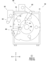
- FIG. 3 is a front view of the hoop winding unit 40 as viewed from the helical winding unit 50 side.
- Figure 4 is a cross-sectional view taken along line IV-IV of Figure 3.
- the hoop winding unit 40 has, for example, a main body portion 41 and a rotating portion 42.
- the main body portion 41 is movable in the front-rear direction along the rail 21.
- the rotating portion 42 is an annular portion in which a passing hole 44 is formed, through which the liner L can pass.
- the rotating portion 42 is supported by the main body portion 41 in a state in which it can rotate around the axis of the liner L.
- the rotating unit 42 has a rotating base 61 and a cartridge 62. Both the rotating base 61 and the cartridge 62 are annular members in which a through hole 44 is formed.
- the rotating base 61 is rotatably supported by the main body 41.
- the cartridge 62 is configured to be detachable from the rotating base 61. More specifically, the rear surface of the rotating base 61 is formed with a plurality of protrusions (not shown) extending in the front-rear direction, and the front surface of the cartridge 62 is formed with a plurality of insertion holes (not shown) into which the protrusions can be inserted.
- the protrusions of the rotating base 61 are inserted into the insertion opening of the cartridge 62, so that the cartridge 62 is attached in a state where it is positioned relative to the rear surface of the rotating base 61.
- the protrusions of the rotating base 61 are pulled out of the insertion opening of the cartridge 62.
- the hoop winding unit 40 has multiple bobbin holders 63 (five in this embodiment), multiple rollers 64 (seven in this embodiment), multiple tension rollers 65 (three in this embodiment), and a guide unit 66.
- the multiple bobbin holders 63, the multiple rollers 64, the multiple tension rollers 65, and the guide unit 66 are attached to the rear surface of the cartridge 62 (i.e., the helical winding unit 50 side).
- Each component attached to the cartridge 62 rotates around the axis of the liner L as the cartridge 62 rotates.
- the bobbin holders 63 are arranged at approximately equal intervals in the circumferential direction of the cartridge 62.
- Each bobbin holder 63 has a rotation shaft extending in the front-rear direction and rotatably supports a bobbin (not shown) on which a fiber bundle is wound.
- the rollers 64 are arranged radially outward of the cartridge 62 from the bobbin holders 63.
- the rollers 64 are arranged at approximately equal intervals in the circumferential direction of the cartridge 62.
- Each roller 64 has a rotation shaft extending in the front-rear direction.
- the fiber bundles F drawn from the bobbins attached to the bobbin holders 63 are hung on the rollers 64 in order in a clockwise direction in FIG. 3.
- the roller 64 is configured as a multiple roller capable of hanging multiple fiber bundles F.
- the five fiber bundles F hung on the cross-hatched roller 64 are supplied to the liner L via the fiber bundle guide 71.
- the guide unit 66 has a fiber bundle guide 71 and a guide motor (not shown).
- the fiber bundle guide 71 is for supplying the fiber bundle F to the liner L.
- the fiber bundle guide 71 is configured to be rotatable about a rotation axis (not shown) that extends along the radial direction of the cartridge 62 (i.e., the radial direction of the rotating part 42) and to be extendable and retractable in the radial direction of the cartridge 62.
- the guide motor rotates and retracts the fiber bundle guide 71. The operation of the guide motor is controlled by the control device 5.
- the hoop winding unit 40 has a moving motor 46 and a rotating motor 47 (see FIG. 2).
- the moving motor 46 moves the main body 41 in the front-rear direction along the rail 21.
- the rotating motor 47 rotates the rotating part 42 around the axis of the liner L. More specifically, the rotating motor 47 rotates the rotating base 61 and the cartridge 62 integrally around the axis of the liner L.
- the operation of the moving motor 46 and the rotating motor 47 is controlled by the control device 5.
- the control device 5 rotates the rotating part 42 while moving the main body 41 back and forth along the rail 21. As a result, fiber bundles are pulled out from each bobbin rotating around the liner L, and multiple fiber bundles are simultaneously hoop-wound around the circumferential surface of the liner L.
- the hoop winding unit 40 has a capture unit 81, a first moving mechanism 82, a cutting unit 91, and a second moving mechanism 92.
- FIG. 5 is a perspective view of the capture unit 81.
- FIG. 6 is a perspective view of the cutting unit 91.
- the capture unit 81 has a capture section 83 that captures the fiber bundle F between the fiber bundle guide 71 and the liner L, and a support member 84 that supports the capture section 83 at one end.
- the capture section 83 is a cylindrical roller whose axis of rotation is the axial direction of the liner L (i.e., the front-to-rear direction).
- the capture section 83 may be configured to rotate freely, or may be configured to be non-rotatable.
- a heater is built into the capture section 83, and the fiber bundle F can be thermally fixed to the outer peripheral surface of the liner L by contacting the outer peripheral surface of the liner L around which the fiber bundle F is wound.
- the capture section 83 also functions as a fixing section of the present invention.
- the first moving mechanism 82 moves the capture unit 81.
- the first moving mechanism 82 has a first arm 85 and a first arm moving mechanism 86 (see Figures 3 and 4).
- the first arm moving mechanism 86 moves the first arm 85 in the front-rear and left-right directions.
- the first arm moving mechanism 86 has a moving member 86a that can move in the left-right direction and an expandable member 86b that can expand and contract in the front-rear direction (see Figure 4).
- the moving member 86a is configured to be able to move in the left-right direction along a rail 55 provided on the upper surface of the main body 41 (see Figures 3 and 4).
- the expandable member 86b is a member that extends in the front-rear direction.
- the front end of the expandable member 86b is connected to the moving member 86a, and the rear end of the expandable member 86b is connected to the first arm 85.
- the expandable member 86b is configured to be able to expand and contract in the front-rear direction.
- the first arm moving mechanism 86 moves the first arm 85 in the left-right direction by moving the moving member 86a in the left-right direction, and moves the first arm 85 in the front-back direction by expanding and contracting the expandable member 86b in the front-back direction.
- the movement of the moving member 86a and the expansion and contraction of the expandable member 86b are driven, for example, by a motor (not shown).
- the first arm 85 is a multi-joint arm having multiple joints. Specifically, as shown in FIG. 3, the first arm 85 has two rotating shafts 87a and 87b parallel to the front-rear direction, a tip 87c, two arm portions 88a and 88b, and a base 89.
- the base 89 is connected to the rear end of the telescopic member 86b described above.
- the rotating shaft 87a is formed on the base 89.
- the base end of the arm portion 88a is connected to the rotating shaft 87a, and the tip end of the arm portion 88a is connected to the rotating shaft 87b.
- the arm portion 88a can swing around the rotating shaft 87a.
- the base end of the arm portion 88b is connected to the rotating shaft 87b, and the tip end of the arm portion 88b is connected to the tip end 87c.
- the arm portion 88b can swing around the rotating shaft 87b.
- the tip end 87c is connected to the capture unit 81.
- the tip 87c is connected to the base end of the support member 84 on the opposite side to the tip that supports the capture portion 83 (see FIG. 5).
- the capture unit 81 is attached to the tip of the first arm 85.
- the first arm 85 is driven, for example, by a motor (not shown).
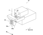
- the cutting unit 91 has a cutting portion 93 and a gripping portion 94.
- the gripping portion 94 grips the fiber bundle F between the fiber bundle guide 71 and the liner L.
- the gripping portion 94 has a pair of clamping portions 94a, 94b.
- the clamping portions 94a and 94b are formed of comb-tooth-shaped members, for example, as shown in FIG. 6.
- the clamping portion 94a is fixed to the cutting unit 91.
- the clamping portion 94b is configured to be movable relative to the clamping portion 94a in an orthogonal direction that is perpendicular to the front-to-rear direction.
- the cutting unit 91 moves the clamping portion 94b in the orthogonal direction toward the clamping portion 94a with the fiber bundle F disposed between the clamping portions 94a and 94b (see the solid arrow in FIG. 6).
- the clamping portions 94a and 94b approach each other, and the fiber bundle F is eventually sandwiched between the clamping portions 94a and 94b (see FIG. 7).
- the movement of the clamping portion 94b is driven by a motor (not shown).
- the cutting section 93 cuts the fiber bundle F between the fiber bundle guide 71 and the liner L. More specifically, the cutting section 93 is configured to cut the fiber bundle F gripped by the gripping section 94.
- the cutting section 93 has a cutting blade 93a for cutting the fiber bundle F.
- the cutting section 93 is configured to be movable in an orthogonal direction perpendicular to the front-rear direction.
- the cutting section 93 is disposed on the opposite side of the gripping section 94a in the orthogonal direction, sandwiching the fiber bundle F.
- the cutting unit 91 moves the cutting section 93 in the orthogonal direction toward the fiber bundle F gripped by the gripping section 94 (see the solid arrow in FIG. 7).
- the movement of the cutting section 93 is driven by a motor (not shown).
- the motor that drives the cutting unit 93 and the motor that drives the gripping unit 94 may be separate motors or may be a common motor.
- the second moving mechanism 92 moves the cutting unit 91.
- the second moving mechanism 92 has a second arm 95 and a second arm moving mechanism 96 (see Figures 3 and 4).
- the second arm moving mechanism 96 moves the second arm 95 in the front-rear direction.
- the second arm moving mechanism 96 has an expandable member 96a that can expand and contract in the front-rear direction (see Figure 4).
- the expandable member 96a is a member that extends rearward from the right side surface of the main body 41.
- the rear end of the expandable member 96a is connected to the second arm 95.
- the second arm moving mechanism 96 moves the second arm 95 in the front-rear direction by the expandable member 96a expanding and contracting in the front-rear direction.
- the expansion and contraction of the expandable member 96a is driven, for example, by a motor (not shown).
- the second arm 95 is a multi-joint arm having multiple joints. Specifically, as shown in FIG. 3, the second arm 95 has two rotation shafts 97a and 97b parallel to the front-rear direction, a tip 97c, two arm portions 98a and 98b, and a base 99.
- the base 99 is connected to the rear end of the telescopic member 96a described above.
- the rotation shaft 97a is formed on the base 89.
- the base end of the arm portion 98a is connected to the rotation shaft 97a, and the tip of the arm portion 98a is connected to the rotation shaft 97b.
- the arm portion 98a can swing around the rotation shaft 97a.
- the base end of the arm portion 98b is connected to the rotation shaft 97b, and the tip of the arm portion 98b is connected to the tip 97c.
- the arm portion 98b can swing around the rotation shaft 97b.
- the tip 97c is connected to the cutting unit 91.
- the cutting unit 91 is attached to the tip of the second arm 95.
- the second arm 95 is driven, for example, by a motor (not shown).
- the hoop winding unit 40 has a detection section 76 that detects that the fiber bundle F has been cut by the cutting section 93, and a notification section 77 that notifies the user that the detection section 76 has detected that the fiber bundle F has been cut.
- the detection section 76 and the notification section 77 are attached to the cutting unit 91 (see FIG. 6).
- the notification section 77 notifies the user that the fiber bundle F has been detected as being cut, for example, by turning on a lamp.
- the operation of the detection section 76 and the notification section 77 is controlled by the control device 5 (see FIG. 2).
- the first moving mechanism 82 moves the capture unit 81 to a predetermined capture position. Specifically, the first moving mechanism 82 moves the capture unit 81 to the capture position by the first arm 85 and the first arm moving mechanism 86.
- the capture position is a position where the capture portion 83 can capture the fiber bundle F that connects from the fiber bundle guide 71 to the outer peripheral surface of the liner L.
- the fiber bundle guide 71 is rotated once around the axis of the liner L (see the solid arrow in FIG. 9)
- the fiber bundle F between the fiber bundle guide 71 and the liner L is captured by the capture portion 83 of the capture unit 81 (see FIG. 10).
- the first moving mechanism 82 adjusts the position of the capturing unit 81 as appropriate, while the second moving mechanism 92 moves the cutting unit 91 to a predetermined cutting position.
- the second moving mechanism 92 moves the cutting unit 91 to the cutting position by means of the second arm 95 and the second arm moving mechanism 96.
- the cutting position is a position where the gripping portion 94 can grip the fiber bundle F captured by the capturing portion 83, and where the cutting portion 93 can cut the fiber bundle F gripped by the gripping portion 94. Note that the first moving mechanism 82 does not have to adjust the position of the capturing unit 81.
- the fiber bundle F is gripped by the gripping portion 94 of the cutting unit 91 in the cutting position.
- the fiber bundle F is cut by the cutting portion 93 of the cutting unit 91 in the cutting position.
- the cutting portion 93 cuts the fiber bundle F between the gripping portion 94 and the liner L.
- the cutting portion 93 cuts the fiber bundle F between the fiber bundle guide 71 and the capturing portion 83.
- the yarn end of the fiber bundle F connected to the liner L is thermally fixed to the outer circumferential surface of the liner L by the capture section 83 with a built-in heater (see FIG. 12).
- the yarn end of the fiber bundle F connected to the fiber bundle guide 71 is held by the gripping section 94 (see FIG. 12).
- the first moving mechanism 82 moves the capture unit 81 to a predetermined standby position
- the second moving mechanism 92 moves the cutting unit 91 to the standby position (see FIG. 13).
- the first arm 85 is in a folded state.
- both the capture unit 81 and the cutting unit 91 are in the standby position. At this time, the yarn end of the fiber bundle F connected to the fiber bundle guide 71 remains gripped by the gripping portion 94 (see FIG. 13).
- the guide unit 66 brings the fiber bundle guide 71 closer to the liner L, which has completed helical winding and is positioned to pass through the passage hole 44 again. Furthermore, the second moving mechanism 92 brings the gripping portion 94, which is gripping the yarn end of the fiber bundle F connected to the fiber bundle guide 71, closer to the outer peripheral surface of the liner L (see FIG. 14). With the gripping portion 94 fixed in a position close to the outer peripheral surface of the liner L, the fiber bundle guide 71 is rotated once around the axis of the liner L (see the solid arrow in FIG. 15). This causes the fiber bundle F to be wound once around the outer peripheral surface of the liner L.
- the fiber bundle guide 71 is rotated around the axis of the liner L to wind the fiber bundle F on and after the second turn onto the liner L.
- the second and subsequent turns of winding are performed while moving the main body 41 back and forth by the moving motor 46 so that the fiber bundle F connected from the gripping portion 94 to the outer peripheral surface of the liner L is stepped on by the fiber bundle F to be wound onto the liner L on and after the second turn.
- the grip of the fiber bundle F by the gripping portion 94 is released. In this manner, the fiber bundle F can be wound onto the liner L and hoop winding can begin.
- the filament winding device 1 of this embodiment is a filament winding device 1 having a hoop winding unit 40 for hoop-winding the fiber bundle F on the outer peripheral surface of a cylindrical liner L.
- the hoop winding unit 40 includes a fiber bundle guide 71 for supplying the fiber bundle F to the liner L, a capture unit 81 having a capture section 83 for capturing the fiber bundle F between the fiber bundle guide 71 and the liner L, a first moving mechanism 82 for moving the capture unit 81, a cutting unit 91 having a cutting section 93 for cutting the fiber bundle F between the fiber bundle guide 71 and the liner L, and a second moving mechanism 92 for moving the cutting unit 91.
- the capture section 83 for capturing the fiber bundle F between the fiber bundle guide 71 and the liner L and the cutting section 93 for cutting the fiber bundle F are moved by separate moving mechanisms. Therefore, the fiber bundle F can be captured by the capture section 83, moved to an appropriate position, and then cut by the cutting section 93. That is, it is possible to improve the degree of freedom as to where to cut the fiber bundle F between the fiber bundle guide 71 and the liner L. Therefore, it is possible to cut the fiber bundle F at a position as close to the liner L as possible, and it is possible to prevent the fiber bundle F hanging down from the liner L after the fiber bundle F is cut from becoming long.
- the cutting unit 91 has a gripping portion 94 that grips the fiber bundle F between the fiber bundle guide 71 and the liner L.
- the cutting portion 93 cuts the fiber bundle F gripped by the gripping portion 94. In this way, by gripping the fiber bundle F with the gripping portion 94, it is possible to prevent the fiber bundle F that comes into contact with the cutting portion 93 from moving away from the cutting portion 93. This makes it easier for the cutting portion 93 to cut the fiber bundle F.
- the cutting section 93 cuts the fiber bundle F between the gripping section 94 and the liner L. According to this, when the fiber bundle F extending from the fiber bundle guide 71 to the liner L is cut by the cutting section 93, the fiber bundle F extending from the fiber bundle guide 71 is held by the gripping section 94. Therefore, when helical winding is performed after hoop winding and then hoop winding is performed again, the hoop winding can be started as follows.
- the fiber bundle guide 71 is revolved around the axis of the liner with the gripping section 94 holding the fiber bundle F fixed, thereby winding the fiber bundle F around the outer peripheral surface of the liner L and starting the hoop winding (see Figures 14 and 15).
- the hoop winding can be started smoothly when hoop winding is performed again.
- the cutting section 93 cuts the fiber bundle F between the fiber bundle guide 71 and the capture section 83. This allows the position at which the cutting section 93 cuts the fiber bundle F to be constant regardless of the diameter of the liner L. Therefore, the cutting unit 91 can be moved with a simple operation to appropriately cut the fiber bundle F.
- the first moving mechanism 82 includes a multi-jointed first arm 85 having multiple joints
- the capture unit 81 is attached to the tip of the first arm 85
- the second moving mechanism 92 includes a multi-jointed second arm 95 having multiple joints
- the cutting unit 91 is attached to the tip of the second arm 95.
- the degree of freedom of the position that the cutting unit 93 can take is improved. This further improves the degree of freedom of where to cut the fiber bundle F between the fiber bundle guide 71 and the liner L. Therefore, the fiber bundle F can be cut at a position closer to the outer circumferential surface of the liner L.
- At least one of the capture unit 81 and the cutting unit 91 has a fixing portion for fixing the yarn end of the fiber bundle F that has been cut by the cutting portion 93 and is connected to the liner L to the outer peripheral surface of the liner L. According to this, after the fiber bundle F is cut, the yarn end of the fiber bundle F that is connected to the liner L is fixed to the outer peripheral surface of the liner L, thereby further preventing the fiber bundle F from sagging from the liner L.
- the capture unit 81 has a fixing portion.
- the gripping portion 94 is in a state of gripping the fiber bundle F sent from the fiber bundle guide 71.
- the fixing portion is included in the capture unit 81. Therefore, in order to fix the fiber bundle F to the outer peripheral surface of the liner L, it is sufficient to move the capture unit 81, and there is no need to move the cutting unit 91, which has the gripping portion 94 in a state of gripping the fiber bundle F. This makes it possible to prevent the fiber bundle F gripped by the gripping portion 94 from getting caught on other members, etc.
- the filament winding device 1 of this embodiment includes a detection unit 76 that detects that the fiber bundle F has been cut by the cutting unit 93, and a notification unit 77 that notifies the operator that the detection unit 76 has detected that the fiber bundle F has been cut. This allows the operator to know that the fiber bundle F has been properly cut by the cutting unit 93.
- the cutting unit 91 has a gripping portion 94.
- the cutting unit 91 does not have to have a gripping portion 94.
- the capturing portion 83 of the capturing unit 81 may have the function of gripping the fiber bundle F.
- the capture unit 83 is a cylindrical roller, but is not limited to this shape.
- the capture unit 83 functions as a fixing unit, but a fixing unit may be provided separately from the capture unit 83.
- the fixing unit is included in the capture unit 81, but the fixing unit may be included in the cutting unit 91.
- both the capture unit 81 and the cutting unit 91 may have fixing units.
- the fixing unit provided in the unit close to the yarn end of the fiber bundle F cut by the cutting unit 93 and connected to the liner L fixes the fiber bundle F to the outer peripheral surface of the liner L.
- the fixing unit does not have to be a heat-fixing type, and may be any type that can fix the fiber bundle F to the outer peripheral surface of the liner L.
- a fixing unit does not have to be provided.
- the cutting unit 93 cuts the fiber bundle F between the fiber bundle guide 71 and the capture unit 83.
- the cutting unit 93 may be configured to cut the fiber bundle F between the liner L and the capture unit 83. This allows the fiber bundle F to be cut at a position closer to the outer circumferential surface of the liner L than the capture unit 83. Therefore, after the fiber bundle F is cut, the length of the fiber bundle F that is pulled out from the liner L can be further shortened, and sagging of the fiber bundle F from the liner L can be further suppressed.
- both the first arm 85 and the second arm 95 are multi-joint arms having multiple joints. However, only one of the first arm 85 and the second arm 95 may be an arm having a joint. Also, both the first arm 85 and the second arm 95 may not have a joint.
- first arm 85 and the second arm 95 are not limited to that in the above embodiment. That is, the first arm 85 may be located on the upper side of the main body 41, and the second arm 95 may be located on the right side of the main body.
- the first arm 85 has rotation shafts 87a and 87b parallel to the front-rear direction
- the second arm 95 has two rotation shafts 97a and 97b parallel to the front-rear direction.
- each rotation shaft may be parallel to any direction.
- the tip 87c may have a rotation axis. This improves the degree of freedom of the posture of the capture unit 81. Also, the tip 97c may have a rotation axis. This improves the degree of freedom of the posture of the cutting unit 91.
- the second arm 95 is configured not to move in the vertical direction, but the second arm 95 may be configured to be movable in the vertical direction.
- the detection unit 76 and the notification unit 77 are provided in the cutting unit 91, but this is not limited to the above.
- the detection unit 76 and the notification unit 77 may be provided outside the hoop winding unit 40.
- the notification unit 77 notifies the user that the fiber bundle F has been cut by turning on a lamp.
- the notification unit 77 may also notify the user by displaying a message on a display screen, or by audio.
- the rotating part 42 has a cartridge 62 that is configured to be detachable from the rotating base 61.
- the rotating part 42 may be configured not to have a cartridge 62.
- the guide unit 66 is attached directly to the rotating part 42.
Landscapes
- Engineering & Computer Science (AREA)
- Mechanical Engineering (AREA)
- Chemical & Material Sciences (AREA)
- Composite Materials (AREA)
- Textile Engineering (AREA)
- Moulding By Coating Moulds (AREA)
- Treatment Of Fiber Materials (AREA)
Priority Applications (4)
| Application Number | Priority Date | Filing Date | Title |
|---|---|---|---|
| KR1020257039139A KR20260003069A (ko) | 2023-05-30 | 2024-03-12 | 필라멘트 와인딩 장치 |
| JP2025523282A JPWO2024247434A1 (https=) | 2023-05-30 | 2024-03-12 | |
| DE112024002336.3T DE112024002336T5 (de) | 2023-05-30 | 2024-03-12 | Fadenwickelvorrichtung |
| CN202480033886.1A CN121219125A (zh) | 2023-05-30 | 2024-03-12 | 长丝卷绕装置 |
Applications Claiming Priority (2)
| Application Number | Priority Date | Filing Date | Title |
|---|---|---|---|
| JP2023088697 | 2023-05-30 | ||
| JP2023-088697 | 2023-05-30 |
Publications (1)
| Publication Number | Publication Date |
|---|---|
| WO2024247434A1 true WO2024247434A1 (ja) | 2024-12-05 |
Family
ID=93657060
Family Applications (1)
| Application Number | Title | Priority Date | Filing Date |
|---|---|---|---|
| PCT/JP2024/009460 Ceased WO2024247434A1 (ja) | 2023-05-30 | 2024-03-12 | フィラメントワインディング装置 |
Country Status (5)
| Country | Link |
|---|---|
| JP (1) | JPWO2024247434A1 (https=) |
| KR (1) | KR20260003069A (https=) |
| CN (1) | CN121219125A (https=) |
| DE (1) | DE112024002336T5 (https=) |
| WO (1) | WO2024247434A1 (https=) |
Citations (5)
| Publication number | Priority date | Publication date | Assignee | Title |
|---|---|---|---|---|
| JP2013063584A (ja) * | 2011-09-16 | 2013-04-11 | Murata Machinery Ltd | フィラメントワインディング方法及びフィラメントワインディング装置 |
| JP2014205305A (ja) * | 2013-04-12 | 2014-10-30 | 村田機械株式会社 | フィラメントワインディング装置 |
| JP2015003405A (ja) * | 2013-06-19 | 2015-01-08 | トヨタ自動車株式会社 | タンクの製造方法および繊維巻付装置 |
| JP2015039853A (ja) * | 2013-08-22 | 2015-03-02 | 村田機械株式会社 | フィラメントワインディング装置 |
| JP2020111002A (ja) * | 2019-01-15 | 2020-07-27 | 村田機械株式会社 | フィラメントワインディング装置 |
-
2024
- 2024-03-12 CN CN202480033886.1A patent/CN121219125A/zh active Pending
- 2024-03-12 KR KR1020257039139A patent/KR20260003069A/ko active Pending
- 2024-03-12 DE DE112024002336.3T patent/DE112024002336T5/de active Pending
- 2024-03-12 WO PCT/JP2024/009460 patent/WO2024247434A1/ja not_active Ceased
- 2024-03-12 JP JP2025523282A patent/JPWO2024247434A1/ja active Pending
Patent Citations (5)
| Publication number | Priority date | Publication date | Assignee | Title |
|---|---|---|---|---|
| JP2013063584A (ja) * | 2011-09-16 | 2013-04-11 | Murata Machinery Ltd | フィラメントワインディング方法及びフィラメントワインディング装置 |
| JP2014205305A (ja) * | 2013-04-12 | 2014-10-30 | 村田機械株式会社 | フィラメントワインディング装置 |
| JP2015003405A (ja) * | 2013-06-19 | 2015-01-08 | トヨタ自動車株式会社 | タンクの製造方法および繊維巻付装置 |
| JP2015039853A (ja) * | 2013-08-22 | 2015-03-02 | 村田機械株式会社 | フィラメントワインディング装置 |
| JP2020111002A (ja) * | 2019-01-15 | 2020-07-27 | 村田機械株式会社 | フィラメントワインディング装置 |
Also Published As
| Publication number | Publication date |
|---|---|
| DE112024002336T5 (de) | 2026-03-12 |
| KR20260003069A (ko) | 2026-01-06 |
| CN121219125A (zh) | 2025-12-26 |
| JPWO2024247434A1 (https=) | 2024-12-05 |
Similar Documents
| Publication | Publication Date | Title |
|---|---|---|
| JP5206949B2 (ja) | フィラメントワインディング装置及び方法 | |
| JP4420250B2 (ja) | フィラメントワインディング装置 | |
| JP7099337B2 (ja) | フィラメントワインディング装置 | |
| US8695318B2 (en) | Method and system for manufacturing cable bead | |
| JP6825428B2 (ja) | フィラメントワインディング装置 | |
| JP7083705B2 (ja) | 巻線装置及びそれを用いた巻線方法 | |
| JP7027112B2 (ja) | 繊維機械の作業台、繊維機械の作業台の空気圧式糸貯蔵要素および繊維機械 | |
| JP5903398B2 (ja) | フィラメントワインディング装置 | |
| JP6897784B2 (ja) | フィラメントワインディング装置、及び、フィラメントワインディング装置における糸掛け方法 | |
| JPH05338043A (ja) | フィラメントワインディング成形装置およびその使用方法 | |
| WO2024247434A1 (ja) | フィラメントワインディング装置 | |
| JP5081892B2 (ja) | 柄経糸用部分整経機および柄経糸を製造するための方法 | |
| JP5339022B2 (ja) | フィラメントワインディング装置 | |
| JP2005089173A (ja) | 糸状物の巻取り方法及び装置 | |
| JP6371079B2 (ja) | 長尺物巻き取り装置 | |
| WO2024247548A1 (ja) | フィラメントワインディング装置 | |
| JP2024171561A (ja) | フィラメントワインディング装置 | |
| JP7732966B2 (ja) | フィラメントワインディング装置及びフィラメントワインディング方法 | |
| JP2024171603A (ja) | 作業台 | |
| JP2018511542A (ja) | 巻き取られた糸ストランドを取り扱う装置および方法 | |
| JP2024171473A (ja) | フィラメントワインディング装置 | |
| JPH08318499A (ja) | ロープの巻付切断装置 | |
| JPH0373262A (ja) | 線材の磨き方法 | |
| JPH0363946B2 (https=) | ||
| JPH04266363A (ja) | 線条体のボビンへの掛け替え装置 |
Legal Events
| Date | Code | Title | Description |
|---|---|---|---|
| 121 | Ep: the epo has been informed by wipo that ep was designated in this application |
Ref document number: 24814921 Country of ref document: EP Kind code of ref document: A1 |
|
| ENP | Entry into the national phase |
Ref document number: 2025523282 Country of ref document: JP Kind code of ref document: A |
|
| WWE | Wipo information: entry into national phase |
Ref document number: CN2024800338861 Country of ref document: CN |
|
| ENP | Entry into the national phase |
Ref document number: 1020257039139 Country of ref document: KR Free format text: ST27 STATUS EVENT CODE: A-0-1-A10-A15-NAP-PA0105 (AS PROVIDED BY THE NATIONAL OFFICE) |
|
| WWE | Wipo information: entry into national phase |
Ref document number: KR1020257039139 Country of ref document: KR |
|
| WWE | Wipo information: entry into national phase |
Ref document number: 112024002336 Country of ref document: DE |
|
| WWP | Wipo information: published in national office |
Ref document number: 112024002336 Country of ref document: DE |