WO2024247127A1 - 工作機械の制御装置 - Google Patents
工作機械の制御装置 Download PDFInfo
- Publication number
- WO2024247127A1 WO2024247127A1 PCT/JP2023/020168 JP2023020168W WO2024247127A1 WO 2024247127 A1 WO2024247127 A1 WO 2024247127A1 JP 2023020168 W JP2023020168 W JP 2023020168W WO 2024247127 A1 WO2024247127 A1 WO 2024247127A1
- Authority
- WO
- WIPO (PCT)
- Prior art keywords
- swing
- condition
- unit
- oscillation
- conditions
- Prior art date
- Legal status (The legal status is an assumption and is not a legal conclusion. Google has not performed a legal analysis and makes no representation as to the accuracy of the status listed.)
- Ceased
Links
Images



Classifications
-
- B—PERFORMING OPERATIONS; TRANSPORTING
- B23—MACHINE TOOLS; METAL-WORKING NOT OTHERWISE PROVIDED FOR
- B23Q—DETAILS, COMPONENTS, OR ACCESSORIES FOR MACHINE TOOLS, e.g. ARRANGEMENTS FOR COPYING OR CONTROLLING; MACHINE TOOLS IN GENERAL CHARACTERISED BY THE CONSTRUCTION OF PARTICULAR DETAILS OR COMPONENTS; COMBINATIONS OR ASSOCIATIONS OF METAL-WORKING MACHINES, NOT DIRECTED TO A PARTICULAR RESULT
- B23Q15/00—Automatic control or regulation of feed movement, cutting velocity or position of tool or work
- B23Q15/007—Automatic control or regulation of feed movement, cutting velocity or position of tool or work while the tool acts upon the workpiece
- B23Q15/12—Adaptive control, i.e. adjusting itself to have a performance which is optimum according to a preassigned criterion
-
- G—PHYSICS
- G05—CONTROLLING; REGULATING
- G05B—CONTROL OR REGULATING SYSTEMS IN GENERAL; FUNCTIONAL ELEMENTS OF SUCH SYSTEMS; MONITORING OR TESTING ARRANGEMENTS FOR SUCH SYSTEMS OR ELEMENTS
- G05B19/00—Program-control systems
- G05B19/02—Program-control systems electric
- G05B19/18—Numerical control [NC], i.e. automatically operating machines, in particular machine tools, e.g. in a manufacturing environment, so as to execute positioning, movement or co-ordinated operations by means of program data in numerical form
- G05B19/416—Numerical control [NC], i.e. automatically operating machines, in particular machine tools, e.g. in a manufacturing environment, so as to execute positioning, movement or co-ordinated operations by means of program data in numerical form characterised by control of velocity, acceleration or deceleration
Definitions
- This disclosure relates to a control device for a machine tool.
- the swing operation When using a method of superimposing a swing command on a movement command as a means of achieving swing cutting, the swing operation has acceleration and deceleration superimposed on it that is not included in the machining command when swing machining is not performed. As a result, the acceleration and deceleration energy required during machining increases compared to when swing machining is not performed. Depending on the object to be machined and the purpose of the machining, it may be desirable to reduce the increased or decreased acceleration and deceleration energy as much as possible.
- This disclosure has been made in consideration of the above problems, and aims to provide a technology in a machine tool control device that can reduce acceleration and deceleration energy during oscillating machining according to the purpose and application.
- the present disclosure relates to a control device for a machine tool that performs swing machining by swinging a workpiece and a tool relative to one another
- the control device for a machine tool comprising: a swing condition setting unit that sets swing conditions; a swing condition calculation unit that calculates swing conditions different from the swing conditions in order to reduce the acceleration/deceleration energy required for the swing operation determined by the swing conditions; a swing condition selection unit that selects one of the swing conditions set by the swing condition setting unit and the swing condition calculation unit; a swing command calculation unit that calculates a swing command based on the swing conditions selected by the swing condition selection unit; and a control unit that swings the workpiece and the tool relative to one another based on a movement command on which the swing command is superimposed.
- This disclosure provides a technology for controlling a machine tool's control device that can reduce acceleration and deceleration energy during oscillating machining according to the purpose and application.
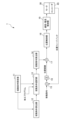
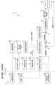
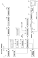
- FIG. 2 is a functional block diagram of the control device for the machine tool according to the first embodiment.
- 11 is a graph showing the relationship between speed and time when feeding is constant.
- 11 is a graph showing the relationship between speed and time when a swing command is superimposed.
- 13 is a graph showing the relationship between speed and time when the oscillation conditions are changed.
- FIG. 11 is a functional block diagram of a control device for a machine tool according to a second embodiment.
- FIG. 11 is a functional block diagram of a control device for a machine tool according to a third embodiment.
- FIG. 13 is a functional block diagram of a control device for a machine tool according to a fourth embodiment.
- FIG. 13 is a functional block diagram of a control device for a machine tool according to a fifth embodiment.
- FIG. 11 is a graph showing the relationship between speed and time when feeding is constant.
- 11 is a graph showing the relationship between speed and time when a swing command is superimposed.
- 13 is a graph showing the relationship between
- FIG. 13 is a functional block diagram of a control device for a machine tool according to a sixth embodiment.
- FIG. 13 is a functional block diagram of a control device for a machine tool according to a seventh embodiment.
- FIG. 23 is a functional block diagram of a control device for a machine tool according to an eighth embodiment.
- FIG. 13 is a functional block diagram of a control device for a machine tool according to a 9th embodiment.
- FIG. 1 is a functional block diagram of a machine tool control device 1 according to the first embodiment.
- the machine tool control device 1 is a computer that controls a machine tool that generates an air cut in cutting a workpiece to break up chips by superimposing a swing command that commands relative swing between the workpiece and the cutting tool on a movement command that commands relative movement between the workpiece and the cutting tool.
- the machine tool control device 1 is, for example, configured by a numerical control device.
- the control device 1 for the machine tool in this embodiment includes a swing condition setting unit 11, a swing condition calculation unit 12, a swing condition selection unit 13, a swing command calculation unit 14, a first adder 15, an integrator 16, a second adder 17, a position control unit 18, and a speed/current control unit 19.
- the oscillation condition setting unit 11 sets the oscillation conditions.
- the oscillation conditions are set by the user.
- the oscillation conditions are specified in the machining program or set as parameters of the control device 1 of the machine tool.
- the oscillation condition setting unit 11 sets amplitude information indicating the oscillation amplitude or oscillation amplitude magnification and frequency information indicating the oscillation frequency or oscillation frequency magnification as the oscillation conditions.
- the oscillation conditions consisting of the oscillation amplitude or oscillation amplitude magnification and the oscillation frequency or oscillation frequency magnification are input to the oscillation condition selection unit 13.
- the oscillation conditions include at least a frequency parameter, which is information about the oscillation frequency of the cutting tool or workpiece, and an amplitude parameter, which is information about the oscillation amplitude of the cutting tool or workpiece, as information for uniquely identifying the vibration waveform.
- the frequency parameter may be the relative oscillation frequency per rotation of the cutting tool and workpiece, or the oscillation frequency per unit time. It may also be a periodic parameter of the forward and backward motion.
- the amplitude parameter may be information about the oscillation amplitude relative to the relative feed amount per rotation of the cutting tool and workpiece, or a distance parameter of the forward and backward motion.
- These periodic parameters of the forward and backward motion and distance parameters of the forward and backward motion may be determined from the forward speed, backward speed, forward distance, backward distance, spindle rotation speed, control period, etc.
- the frequency parameter and amplitude parameter may also be determined from the spindle rotation speed, feed rate per minute, frequency multiplication, which is the relative oscillation frequency per rotation of the cutting tool and workpiece, and amplitude multiplication, which is the oscillation amplitude relative to the relative feed amount per rotation of the cutting tool and workpiece, etc.
- the oscillation condition calculation unit 12 calculates oscillation conditions (amplitude information and frequency information) different from those of the oscillation condition setting unit 11 in order to suppress the acceleration/deceleration energy required for the oscillation operation.
- Figure 2 is a graph showing the relationship between speed and time when feeding at a constant speed.
- Figure 3 is a graph showing the relationship between speed and time when an oscillation command is superimposed.
- the speed after the swing command is superimposed can be expressed as in the following formula (1).
- v indicates the speed after the swing command is superimposed
- F indicates a constant feed speed
- K indicates the swing amplitude magnification (an example of amplitude information)
- I indicates the swing frequency magnification (an example of frequency information)
- S indicates the spindle rotation speed
- t indicates time.
- the acceleration/deceleration energy required for swing operation can be found by multiplying the second term on the right side of formula (1) by the mass m of the object performing the swing operation and integrating it over time t. Note that mass m is not necessarily required when discussing energy. For example, if mass m is constant, the increase or decrease in energy can be confirmed by integrating the speed over time t.
- FIG. 4 is a graph showing the relationship between speed and time when the oscillation conditions are changed.
- the acceleration/deceleration energy required for the oscillation operation can be reduced by reducing the oscillation amplitude magnification K or the oscillation frequency magnification I.
- the oscillation condition calculation unit 12 calculates the oscillation conditions so that the oscillation amplitude magnification K, the oscillation frequency magnification I, or both are reduced.
- the oscillation amplitude magnification K and the oscillation frequency magnification I are in a trade-off relationship with chip shredding. If the oscillation amplitude magnification K is made smaller, the amplitude margin required for air cutting is reduced, making air cutting more difficult. If the oscillation frequency magnification I is made smaller, the phase for air cutting shifts, making air cutting more difficult.
- the oscillation condition calculation unit 12 calculates amplitude information and frequency information as oscillation conditions based on formulas and coefficients that reflect the user's intention for air cutting. The oscillation conditions calculated by the oscillation condition calculation unit 12 are input to the oscillation condition selection unit 13.
- the oscillation condition selection unit 13 selects the oscillation conditions based on the selection conditions set by the user. In the first embodiment, the oscillation condition selection unit 13 selects either the oscillation conditions of the oscillation condition setting unit 11 or the oscillation condition calculation unit 12 based on the selection conditions specified in the machining program. For example, a code corresponding to "oscillation condition 1" indicating that the oscillation conditions of the oscillation condition setting unit 11 are to be used, or a code corresponding to "oscillation condition 2" indicating that the oscillation conditions of the oscillation condition calculation unit 12 are to be used, etc. are specified in the machining program.
- the oscillation command calculation unit 14 calculates an oscillation command based on the oscillation conditions selected by the oscillation condition selection unit 13.
- the oscillation command calculated by the oscillation command calculation unit 14 is input to the second adder 17.
- the first adder 15 calculates the position deviation.
- the first adder 15 calculates the position deviation, which is the difference between the movement command and the position feedback based on the position detection by the encoder 45 of the feed axis motor 30.
- the position deviation calculated by the first adder 15 is input to the integrator 16.
- the integrator 16 calculates the integrated value of the position deviation. Specifically, the integrator 16 calculates the integrated value of the position deviation by integrating the position deviation calculated by the first adder 15. The integrated value integrated by the integrator 16 is input to the second adder 17.
- the second adder 17 generates a superimposition command. Specifically, the second adder 17 generates a superimposition command by adding (superimposing) the swing command generated by the swing command calculation unit 14 to the integrated value of the position deviation calculated by the integrator 16. The superimposition command generated by the second adder 17 is input to the position control unit 18. Note that the processing related to the position deviation may be omitted, and the second adder 17 may be configured to add the swing command generated by the swing command calculation unit 14 to the movement command (position command).
- the position control unit 18 generates a position command based on the superimposed command and outputs it to the speed/current control unit 19.
- the speed/current control unit 19 outputs an operation command to the motor 30 to control the speed and current based on the position command. This allows the machine tool to perform oscillating machining, which oscillates the workpiece and the tool relative to one another.
- the control device 1 of the machine tool of the first embodiment includes a swing condition setting unit 11 that sets swing conditions, a swing condition calculation unit 12 that calculates swing conditions different from the swing conditions determined by the swing conditions in order to reduce the acceleration/deceleration energy required for the swing operation, a swing condition selection unit 13 that selects one of the swing conditions set by the swing condition setting unit 11 and the swing condition calculation unit 12, a swing command calculation unit 14 that calculates a swing command based on the swing condition selected by the swing condition selection unit 13, and a control unit (position control unit 18, speed/current control unit 19) that swings the workpiece and the tool relatively based on a movement command on which the swing command is superimposed.
- a control unit position control unit 18, speed/current control unit 19
- the oscillation condition selection unit 13 can select to relax the oscillation conditions, thereby reducing the acceleration/deceleration energy that increases as a result of performing oscillation processing.
- oscillation processing can be performed with appropriate acceleration/deceleration energy according to the user's purpose.
- the oscillation condition setting unit 11 sets amplitude information indicating the oscillation amplitude (e.g., oscillation amplitude, oscillation amplitude magnification) and frequency information indicating the oscillation frequency (e.g., oscillation frequency, oscillation frequency magnification) as the oscillation conditions, and the oscillation condition calculation unit 12 calculates set values obtained by varying the amplitude information and frequency information as the oscillation conditions. This makes it possible to relax the oscillation conditions by changing the numerical values of the amplitude information indicating the oscillation amplitude and the frequency information indicating the oscillation frequency.
- the oscillation condition selection unit 13 selects one of the oscillation conditions set by the oscillation condition setting unit 11 and the oscillation condition calculation unit 12 based on the specifications in the machining program. This makes it easy to set whether or not to relax the oscillation conditions by specifying the machining program.
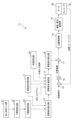
- FIG. 5 is a functional block diagram of a machine tool control device 1a according to the second embodiment.
- the machine tool control device 1a of the second embodiment further includes a machining condition input unit 21, a lower limit value calculation unit 22, and a lower limit value setting unit 23 in addition to the configuration of the first embodiment.
- the machining condition input unit 21 inputs the machining conditions to the lower limit calculation unit 22.
- the machining conditions in this embodiment are parameters necessary for machining that are set in addition to the oscillation conditions, such as the spindle speed and feed axis speed.
- the machining conditions are, for example, specified in the machining program or set as parameters of the control device 1a of the machine tool.
- the lower limit calculation unit 22 calculates the lower limit of at least one of the amplitude information and the frequency information based on the input processing conditions.
- the lower limit calculation unit 22 calculates, for example, the conditions of the amplitude information and the frequency information required to generate an air cut for the processing conditions.
- the lower limit setting unit 23 calculates the condition calculated by the lower limit calculation unit 22 into a lower limit value.
- the lower limit value set by the lower limit setting unit 23 is input to the oscillation condition calculation unit 12.
- the oscillation condition calculation unit 12 of the second embodiment calculates the amplitude information and frequency information based on the preset setting conditions and the lower limit value set by the lower limit value setting unit 23.
- the setting conditions of the second embodiment are that the calculated amplitude information and frequency information are smaller than the product of the amplitude information and frequency information set by the oscillation condition setting unit 11.
- the oscillation condition calculation unit 12 calculates the amplitude information and frequency information so as to exceed the lower limit value of the amplitude information and the lower limit value of the frequency information while satisfying the set conditions.
- the calculated amplitude information and frequency information are input to the oscillation condition selection unit 13.
- the subsequent processing is the same as in the first embodiment.
- control device 1a of the machine tool in the second embodiment further includes a lower limit setting unit 23 that sets a lower limit value for at least one of the set values of the amplitude information and the frequency information, and the product of the amplitude information and the frequency information calculated by the oscillation condition calculation unit 12 is smaller than the product of the amplitude information and the frequency information set by the oscillation condition setting unit 11 and is greater than the lower limit value.
- the configuration of this embodiment sets a lower limit, making it possible to avoid a situation in which chip shredding performance reaches zero.
- the acceleration/deceleration energy is proportional to the square of the product of the oscillation frequency and the oscillation amplitude.
- the product of the oscillation frequency and the oscillation amplitude calculated by the lower limit calculation unit 22 is smaller than the product of the oscillation frequency and the oscillation amplitude of the set value, so that the acceleration/deceleration energy can be reliably suppressed.
- the control device 1a for the machine tool in the second embodiment further includes a machining condition input unit 21 for inputting machining conditions, and a lower limit calculation unit 22 for calculating the conditions of amplitude information and frequency information required to generate an air cut based on the machining conditions, and a lower limit setting unit 23 sets the conditions of amplitude information and frequency information calculated by the lower limit calculation unit 22 as lower limits.
- the machine tool control device 1a is configured to include a machining condition input unit 21, a lower limit calculation unit 22, and a lower limit setting unit 23, but is not limited to this configuration.
- the machining condition input unit 21 and the lower limit calculation unit 22 may be omitted from the machine tool control device 1a.
- a numerical value that is theoretically or empirically set as the lower limit value of at least one of the amplitude information and the frequency information may be set in advance in the lower limit setting unit 23, and the oscillation condition calculation unit 12 may calculate the amplitude information and the frequency information based on the lower limit value.
- FIG. 6 is a functional block diagram of a machine tool control device 1b according to the third embodiment.
- an external signal is input to a swing condition selection unit 13 in addition to the configuration of the second embodiment.
- the external signal includes information for selecting the oscillation conditions.
- the external signal is, for example, a signal that specifies an energy-saving mode that reduces acceleration/deceleration energy from an operating means (not shown) or an external computer.
- the oscillation condition selection unit 13 selects the oscillation conditions calculated by the oscillation condition calculation unit 12.
- the swing condition selection unit 13 of the control device 1b of the machine tool in the third embodiment selects one of the swing conditions set by the swing condition setting unit 11 and the swing condition calculation unit 12 based on a signal input from the outside. This makes it possible to use the external signal to determine whether or not to relax the swing conditions depending on the situation.
- FIG. 7 is a functional block diagram of a machine tool control device 1c according to the fourth embodiment.
- the machine tool control device 1c of the fourth embodiment further includes a section setting unit 24 in addition to the configuration of the second embodiment.
- the section setting unit 24 inputs a pre-specified processing section, processing time, or both to the oscillation condition selection unit 13.
- the information input from the section setting unit 24 to the oscillation condition selection unit 13 specifies the oscillation conditions to be selected for each of the specified processing section, processing time, or both.
- machining section A it is set to adopt the oscillation conditions set by the oscillation condition setting section 11, and for another machining section B, it is set to adopt the oscillation conditions calculated by the oscillation condition calculation section 12.
- machining condition calculation section 12 it is set to adopt the oscillation conditions calculated by the oscillation condition calculation section 12, and for another machining time D, it is set to adopt the oscillation conditions set by the oscillation condition setting section 11.
- the section setting unit 24 can also specify the oscillation conditions to be adopted by combining the processing section and the processing time. For example, it is possible to perform oscillation processing so that the oscillation conditions calculated by the oscillation condition calculation unit 12 are adopted only when the processing section is B and the processing time is C.
- the swing condition selection unit 13 of the control device 1c of the machine tool in the fourth embodiment selects one of the swing conditions set by the swing condition setting unit 11 and the swing condition calculation unit 12, respectively, based on at least one of a pre-specified machining section and machining time. This makes it possible to reduce acceleration and deceleration energy by relaxing the swing conditions according to the desired machining section and machining time. Swing machining is realized under swing conditions optimized according to the machining state.
- [Fifth embodiment] 8 is a functional block diagram of a machine tool control device 1d according to the fifth embodiment.
- the machine tool control device 1d of the fifth embodiment further includes a variable condition storage unit 25 in addition to the configuration of the second embodiment.
- the variable condition storage unit 25 stores the variable conditions for the oscillation condition calculation unit 12 to calculate the amplitude information and frequency information.
- a plurality of variable conditions are stored, such as “strong energy saving” which reduces the acceleration/deceleration energy by a relatively large amount, “weak energy saving” which reduces the acceleration/deceleration energy by a relatively small amount, and “normal” which reduces the acceleration/deceleration energy by a medium amount.
- strong energy saving which reduces the acceleration/deceleration energy by a relatively large amount
- weak energy saving which reduces the acceleration/deceleration energy by a relatively small amount
- normal which reduces the acceleration/deceleration energy by a medium amount.
- the oscillation condition calculation unit 12 calls up the fluctuation conditions stored in the fluctuation condition storage unit 25, and calculates amplitude information and frequency information according to the fluctuation conditions.
- the amplitude information and frequency information calculated by the oscillation condition calculation unit 12 are input to the oscillation condition selection unit 13.
- the oscillation condition selection unit 13 outputs amplitude information and frequency information corresponding to the fluctuation conditions selected based on the specifications of the machining program, etc., to the oscillation command calculation unit 14.
- the subsequent processing is the same as in the above embodiment.
- the machine tool control device 1d of the fifth embodiment further includes a variation condition storage unit 25 that stores multiple variation conditions for the oscillation condition calculation unit 12 to vary the amplitude information and frequency information, and the oscillation condition calculation unit 12 can calculate oscillation conditions for each of the multiple variation conditions stored by the variation condition storage unit 25. This makes it possible to adjust the amount of reduction in acceleration/deceleration energy according to the purpose, further improving user convenience.
- the oscillation condition calculation unit 12 is configured to calculate the amplitude information and frequency information based on each fluctuation condition, but this is not limited to the configuration.
- the oscillation condition calculation unit 12 may be configured to first receive the selection result of the oscillation condition selection unit 13, and calculate the amplitude information and frequency information based on the fluctuation condition corresponding to the selection result.
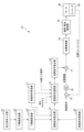
- Sixth Embodiment 9 is a functional block diagram of a machine tool control device 1e according to the sixth embodiment.
- the machine tool control device 1e of the sixth embodiment further includes an energy calculation unit 26 and a display unit 27 in addition to the configuration of the third embodiment.
- the energy calculation unit 26 calculates the acceleration and deceleration energy required for the rocking operation based on the input rocking conditions.
- the energy calculation unit 26 receives information indicating the rocking conditions from each of the rocking condition setting unit 11 and the rocking condition calculation unit 12.
- the energy calculation unit 26 calculates the acceleration and deceleration energy corresponding to each received rocking condition.
- the acceleration/deceleration energy calculated by the energy calculation unit 26 may be calculated in Joules (J), which generally indicates energy, using the above-mentioned integration, or may be calculated using other calculation methods. For example, it may be output as a CO2 emission amount converted based on a predetermined conversion formula.
- J Joules
- the acceleration/deceleration energy calculated by the energy calculation unit 26 is input to the display unit 27.
- the display unit 27 displays the acceleration/deceleration energy input from the energy calculation unit 26 on a display provided in the machine tool control device 1e or on an external computer. As described above, the display unit 27 notifies the user of the magnitude of the acceleration/deceleration energy in terms of J (Joules) or CO2 emission amount. In the sixth embodiment, the display unit 27 executes a process of displaying the acceleration/deceleration energy corresponding to each of the oscillation conditions of the oscillation condition setting unit 11 and the oscillation condition calculation unit 12. Note that the display unit 27 may not only execute the display process, but may itself be a display.
- the control device 1e of the machine tool in the sixth embodiment further includes an energy calculation unit 26 that calculates the acceleration/deceleration energy required for the swing operation based on the swing conditions, and a display unit 27 that calculates at least one of the energy based on the swing conditions set by the swing condition setting unit 11 and the energy in the swing conditions calculated by the swing condition calculation unit 12, and displays the acceleration/deceleration energy corresponding to the swing conditions.
- an energy calculation unit 26 that calculates the acceleration/deceleration energy required for the swing operation based on the swing conditions
- a display unit 27 that calculates at least one of the energy based on the swing conditions set by the swing condition setting unit 11 and the energy in the swing conditions calculated by the swing condition calculation unit 12, and displays the acceleration/deceleration energy corresponding to the swing conditions.
- FIG. 10 is a functional block diagram of a machine tool control device 1f according to the seventh embodiment.
- the machine tool control device 1f according to the seventh embodiment includes a display device 2 for realizing a GUI (Graphical User Interface) function.
- the display device 2 is configured by, for example, a display means for displaying various information such as a display, and an operation means such as a touch panel, a keyboard, and buttons.
- the machine tool control device 1f further comprises an energy calculation unit 31 and a reference setting unit 32.
- the display device 2 also comprises a reference display unit 41, a target input unit 42, and an oscillation condition display designation unit 43.
- the energy calculation unit 31 calculates the acceleration/deceleration energy required for the rocking operation based on the input rocking conditions.
- the energy calculation unit 31 of the seventh embodiment calculates the acceleration/deceleration energy corresponding to the rocking conditions received from the rocking condition setting unit 11.
- the energy calculation unit 31 may calculate the acceleration/deceleration energy in J (Joules), which generally indicates energy, using the above-mentioned integral, or may use other calculation methods. For example, it may be output as a CO2 emission amount converted based on a predetermined conversion formula.
- Information indicating the acceleration/deceleration energy calculated by the energy calculation unit 31 of the seventh embodiment is input to the reference setting unit 32.
- the reference setting unit 32 outputs information indicating the acceleration/deceleration energy calculated by the energy calculation unit 31 to the reference display unit 41 of the display device 2.
- the reference display section 41 on the display device 2 displays the acceleration/deceleration energy calculated based on the oscillation conditions of the oscillation condition setting section 11 as information indicating the reference.
- the target input unit 42 accepts conditions for calculating the acceleration/deceleration energy specified by the user, and outputs the accepted information to the oscillation condition calculation unit 12.
- the information accepted by the target input unit 42 is the target acceleration/deceleration energy or the reduction rate of the acceleration/deceleration energy with respect to a certain predetermined standard.
- the predetermined standard in the seventh embodiment is the oscillation conditions set in the machining program (oscillation condition setting unit 11).
- the oscillation condition calculation unit 12 of the seventh embodiment calculates oscillation conditions that satisfy the conditions specified in the target input unit 42. There may be one oscillation condition or multiple oscillation conditions that satisfy the specified conditions.
- the calculation result of the oscillation condition calculation unit 12 is output to the oscillation condition display designation unit 43.
- the oscillation condition display designation unit 43 may present multiple patterns of combinations of amplitude information and frequency information.
- the oscillation condition display designation unit 43 displays the calculation results of the oscillation condition calculation unit 12.
- the oscillation condition display designation unit 43 also accepts an operation from a user who has confirmed the display of the calculation results of the oscillation condition calculation unit 12, and determines the user's selection result.
- the oscillation condition display designation unit 43 then outputs the user's selection result to the oscillation condition selection unit 13.
- the oscillation conditions calculated by the oscillation condition calculation unit 12 satisfy the conditions specified by the user (for example, a specified combination of amplitude information and oscillation conditions, an air cut margin setting, etc.).
- the oscillation condition selection unit 13 selects one of the oscillation conditions corresponding to the user's selection result and the oscillation conditions set by the oscillation condition setting unit 11. As in the above embodiment, the selection criteria are set based on the machining program, external signals, etc.
- the seventh embodiment of the control device 1f for a machine tool includes an energy calculation unit 31 that calculates the acceleration/deceleration energy required for the swing operation based on the swing conditions set by the swing condition setting unit 11, a reference display unit 41 that displays information based on the acceleration/deceleration energy calculated by the energy calculation unit 31 as a reference, a target input unit 42 that inputs the target acceleration/deceleration energy or the reduction rate of the acceleration/deceleration energy relative to the reference, and a swing condition display designation unit 43 that displays at least one swing condition calculated by the swing condition calculation unit 12 to satisfy the conditions input by the target input unit 42 and designates at least one of the displayed swing conditions, and the swing condition selection unit 13 selects either the swing condition designated by the swing condition display designation unit 43 or the swing condition set by the swing condition setting unit 11.
- the swing conditions calculated by the swing condition calculation unit 12 correspond to the user's designation, and when the calculation result is selected by the swing condition selection unit 13, swing machining can be performed with an acceleration/deceleration energy that is more in line with the user's wishes.
- FIG. 11 is a functional block diagram of a machine tool control device 1g according to the eighth embodiment.
- the machine tool control device 1g further includes a swing condition input unit 33 in addition to the configuration of the seventh embodiment. Also, the process executed by the energy calculation unit 34 in the eighth embodiment is different from the process executed by the energy calculation unit 31 in the seventh embodiment.
- the oscillation condition input unit 33 outputs reference oscillation conditions to the energy calculation unit 34 in order to provide a reference to the user.
- the reference oscillation conditions output by the oscillation condition input unit 33 may be obtained from parameters set in the machine tool or the control device 1g of the machine tool, or may be obtained by the user from an input means or an external computer, etc.
- the energy calculation unit 34 of the eighth embodiment calculates acceleration/deceleration energy required for rocking operation based on the rocking conditions input from the rocking condition input unit 33.
- the energy calculation unit 34 may calculate the acceleration/deceleration energy in J (Joules), which generally indicates energy, using the above-mentioned integration, or may use other calculation methods. For example, it may be output as a CO2 emission amount converted based on a predetermined conversion formula.
- the acceleration/deceleration energy calculated by the energy calculation unit 34 is output to the reference setting unit 32.
- the standard setting unit 32 outputs information indicating the standard to the standard display unit 41.
- the standard display unit 41 displays information based on the oscillation conditions input by the oscillation condition input unit 33 as the standard acceleration/deceleration energy.
- the subsequent processing is the same as in the seventh embodiment.
- the eighth embodiment of the control device 1g for a machine tool includes a swing condition input unit 33 that inputs swing conditions that are the basis for the acceleration/deceleration energy associated with the swing operation, an energy calculation unit 34 that calculates the acceleration/deceleration energy required for the swing operation based on the swing conditions input by the swing condition input unit 33, a target input unit 42 that uses information based on the acceleration/deceleration energy calculated by the energy calculation unit 34 as a basis and inputs a target acceleration/deceleration energy or a reduction rate of the acceleration/deceleration energy with respect to the basis, and a swing condition display designation unit 43 that displays at least one swing condition calculated by the swing condition calculation unit 12 to satisfy the conditions input by the target input unit 42 and designates at least one of the displayed swing conditions, and the swing condition selection unit 13 selects either the swing condition designated by the swing condition display designation unit 43 or the swing condition set by the swing condition setting unit 11.
- the oscillation conditions calculated by the oscillation condition calculation unit 12 correspond to the user's specifications, and when the calculation result is selected by the oscillation condition selection unit 13, oscillation machining can be performed with acceleration/deceleration energy that is more in line with the user's wishes. Furthermore, the user can specify the acceleration/deceleration energy by referring to the criteria specified by the user or the criteria set based on the machine tool parameters.
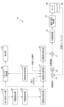
- [Ninth embodiment] 12 is a functional block diagram of a machine tool control device 1h according to the 9th embodiment.
- the machine tool control device 1h of the 9th embodiment further includes a learning unit 50 and a third adder 51.
- the learning unit 50 and the third adder 51 are disposed between the second adder 17 and the position control unit 18.
- the learning unit 50 calculates the correction amount based on the integrated value of the position deviation generated by the second adder 17 and the superimposition command of the oscillation command.
- the learning unit 50 has a memory, and stores in the memory the oscillation phase and the correction amount in association with each other within one or multiple oscillation periods, and reads out the superimposition command stored in the memory at a timing when the phase delay of the oscillation operation according to the responsiveness of the motor 30 can be compensated for, and outputs the superimposition command stored in the memory as a correction amount to the third adder 51. Note that if the oscillation phase for which the correction amount is output does not exist in the oscillation phases stored in the memory, the correction amount to be output may be calculated from a correction amount with a close oscillation phase.
- the third adder 51 adds the correction amount input from the learning unit 50 to the integrated value of the position deviation generated by the second adder 17 and the superimposition command of the oscillation command.
- the superimposition command corrected by the learning unit 50 and the third adder 51 is output to the position control unit 18.
- the subsequent processing is the same as in the above embodiment.
- the control device 1h of the machine tool of the ninth embodiment further includes an encoder 45 as a position detection unit that detects the position information of the motor 30 as a driving body for moving at least one of the workpiece and the tool, a first adder 15 as a position deviation calculation unit that calculates a position deviation from the position information detected by the encoder 45, and a learning unit 50 that calculates a correction amount for the position deviation based on the swing command and the position deviation and corrects the position deviation by adding the calculated correction amount to the position deviation.
- the higher the swing frequency the larger the deviation with respect to the superimposed command.
- the correction by the learning unit 50 can improve the followability to the periodic superimposed command.
- the configuration of this embodiment when the calculation result is selected by the swing condition selection unit 13, swing machining with acceleration/deceleration energy according to the user's intention can be more accurately performed.
- the installation position can be the same as in the ninth embodiment.
- the oscillation condition setting unit (11) sets amplitude information indicating an oscillation amplitude and frequency information indicating an oscillation frequency as the oscillation conditions
- the oscillation condition calculation unit (12) calculates, as the oscillation condition, a set value obtained by varying the amplitude information and the frequency information.
- a lower limit setting unit (23) that sets a lower limit value of at least one of the set values of the amplitude information and the frequency information
- the amplitude information and the frequency information calculated by the oscillation condition calculation unit (12) are such that the product of the calculated amplitude information and the frequency information is smaller than the product of the amplitude information and the frequency information set by the oscillation condition setting unit (11) and is larger than the lower limit value.
- the lower limit setting unit (23) sets the condition of the amplitude information and the frequency information calculated by the lower limit calculation unit (22) as a lower limit.
- the oscillation condition selection section (13) selects one of the oscillation conditions set in the oscillation condition setting section (11) and the oscillation condition calculation section (12) based on a designation in a machining program.
- the oscillation condition selection section (13) selects one of the oscillation conditions set by the oscillation condition setting section (11) and the oscillation condition calculation section (12) based on a signal input from the outside.
- the oscillation condition selection unit (13) selects one of the oscillation conditions set by the oscillation condition setting unit (11) and the oscillation condition calculation unit (12), based on at least one of a pre-specified machining section and machining time.
- the fluctuation condition calculation unit (12) further includes a fluctuation condition storage unit (25) that stores a plurality of fluctuation conditions for varying the amplitude information and the frequency information,
- the fluctuation condition calculation section (12) is capable of calculating a fluctuation condition for each of a plurality of variable conditions stored in the variable condition storage section (25).
- an energy calculation unit (26) that calculates acceleration/deceleration energy required for a swing operation based on the swing conditions;
- the system further includes a display unit (27) that calculates at least one of the energy based on the oscillation conditions set by the oscillation condition setting unit (11) and the energy under the oscillation conditions calculated by the oscillation condition calculation unit (12), and displays the acceleration/deceleration energy corresponding to the oscillation conditions.
- an energy calculation unit (31) that calculates acceleration and deceleration energy required for a swing operation based on the swing conditions set by the swing condition setting unit (11); a reference display unit (41) that displays information based on the acceleration/deceleration energy calculated by the energy calculation unit (31) as a reference; a target input unit (42) for inputting the acceleration/deceleration energy or a reduction rate of the acceleration/deceleration energy as a target with respect to the reference; a display unit (43) that displays at least one oscillation condition calculated by the oscillation condition calculation unit (13) so as to satisfy the condition inputted by the target input unit (42); a designation unit (43) for designating at least one of the oscillation conditions displayed by the display unit (43),
- the oscillation condition selection section (13) selects either the oscillation condition designated by the designation section (43) or the oscillation condition (11) set by the oscillation condition setting section (11).
- a swing condition input unit (33) for inputting swing conditions that are the basis for acceleration/deceleration energy associated with a swing operation; an energy calculation unit (34) that calculates acceleration and deceleration energy required for a swing operation based on the swing conditions input by the swing condition input unit (33); a target input unit (42) for inputting the acceleration/deceleration energy or a reduction rate of the acceleration/deceleration energy as a target with respect to information based on the acceleration/deceleration energy calculated by the energy calculation unit (34) as a standard; a display unit (43) that displays at least one oscillation condition calculated by the oscillation condition calculation unit (13) so as to satisfy the condition inputted by the target input unit (42); and a designation unit (43) for designating at least one of the oscillation conditions displayed by the display unit,
- the oscillation condition selection unit (13) selects either the oscillation condition designated by the designation unit (43) or the oscillation condition set by the oscillation condition setting unit (11).
- a position detection unit (45) that detects position information of a driving body (30) for moving at least one of the workpiece and the tool; a position deviation calculation unit (15) that calculates a position deviation from position information detected by the position detection unit (45);
- the apparatus further includes a learning section (50) that calculates a correction amount for the position deviation based on the swing command and the position deviation, and corrects the position deviation by adding the calculated correction amount to the position deviation.
Landscapes
- Engineering & Computer Science (AREA)
- Human Computer Interaction (AREA)
- Manufacturing & Machinery (AREA)
- Physics & Mathematics (AREA)
- General Physics & Mathematics (AREA)
- Automation & Control Theory (AREA)
- Mechanical Engineering (AREA)
- Numerical Control (AREA)
- Automatic Control Of Machine Tools (AREA)
Priority Applications (4)
| Application Number | Priority Date | Filing Date | Title |
|---|---|---|---|
| JP2025523758A JPWO2024247127A1 (cg-RX-API-DMAC7.html) | 2023-05-30 | 2023-05-30 | |
| CN202380098288.8A CN121219105A (zh) | 2023-05-30 | 2023-05-30 | 机床的控制装置 |
| PCT/JP2023/020168 WO2024247127A1 (ja) | 2023-05-30 | 2023-05-30 | 工作機械の制御装置 |
| DE112023005969.1T DE112023005969T5 (de) | 2023-05-30 | 2023-05-30 | Werkzeugmaschinen-Steuervorrichtung |
Applications Claiming Priority (1)
| Application Number | Priority Date | Filing Date | Title |
|---|---|---|---|
| PCT/JP2023/020168 WO2024247127A1 (ja) | 2023-05-30 | 2023-05-30 | 工作機械の制御装置 |
Publications (1)
| Publication Number | Publication Date |
|---|---|
| WO2024247127A1 true WO2024247127A1 (ja) | 2024-12-05 |
Family
ID=93657191
Family Applications (1)
| Application Number | Title | Priority Date | Filing Date |
|---|---|---|---|
| PCT/JP2023/020168 Ceased WO2024247127A1 (ja) | 2023-05-30 | 2023-05-30 | 工作機械の制御装置 |
Country Status (4)
| Country | Link |
|---|---|
| JP (1) | JPWO2024247127A1 (cg-RX-API-DMAC7.html) |
| CN (1) | CN121219105A (cg-RX-API-DMAC7.html) |
| DE (1) | DE112023005969T5 (cg-RX-API-DMAC7.html) |
| WO (1) | WO2024247127A1 (cg-RX-API-DMAC7.html) |
Citations (5)
| Publication number | Priority date | Publication date | Assignee | Title |
|---|---|---|---|---|
| JP2020074214A (ja) * | 2020-01-29 | 2020-05-14 | ファナック株式会社 | 複数軸を備えた工作機械の制御装置 |
| JP2020163487A (ja) * | 2019-03-28 | 2020-10-08 | ファナック株式会社 | サーボ制御装置 |
| JP2021126766A (ja) * | 2017-08-29 | 2021-09-02 | 国立大学法人東海国立大学機構 | 振動切削装置および接触検出プログラム |
| WO2022085114A1 (ja) * | 2020-10-21 | 2022-04-28 | 三菱電機株式会社 | 数値制御装置及び数値制御方法 |
| JP7158604B1 (ja) * | 2021-06-02 | 2022-10-21 | 三菱電機株式会社 | 数値制御装置、学習装置、推論装置、および数値制御方法 |
-
2023
- 2023-05-30 CN CN202380098288.8A patent/CN121219105A/zh active Pending
- 2023-05-30 DE DE112023005969.1T patent/DE112023005969T5/de active Pending
- 2023-05-30 JP JP2025523758A patent/JPWO2024247127A1/ja active Pending
- 2023-05-30 WO PCT/JP2023/020168 patent/WO2024247127A1/ja not_active Ceased
Patent Citations (5)
| Publication number | Priority date | Publication date | Assignee | Title |
|---|---|---|---|---|
| JP2021126766A (ja) * | 2017-08-29 | 2021-09-02 | 国立大学法人東海国立大学機構 | 振動切削装置および接触検出プログラム |
| JP2020163487A (ja) * | 2019-03-28 | 2020-10-08 | ファナック株式会社 | サーボ制御装置 |
| JP2020074214A (ja) * | 2020-01-29 | 2020-05-14 | ファナック株式会社 | 複数軸を備えた工作機械の制御装置 |
| WO2022085114A1 (ja) * | 2020-10-21 | 2022-04-28 | 三菱電機株式会社 | 数値制御装置及び数値制御方法 |
| JP7158604B1 (ja) * | 2021-06-02 | 2022-10-21 | 三菱電機株式会社 | 数値制御装置、学習装置、推論装置、および数値制御方法 |
Also Published As
| Publication number | Publication date |
|---|---|
| DE112023005969T5 (de) | 2025-12-31 |
| JPWO2024247127A1 (cg-RX-API-DMAC7.html) | 2024-12-05 |
| CN121219105A (zh) | 2025-12-26 |
Similar Documents
| Publication | Publication Date | Title |
|---|---|---|
| JP4467625B2 (ja) | 数値制御装置および数値制御方法 | |
| JP6412197B1 (ja) | 揺動切削を行う工作機械の制御装置 | |
| US10509387B2 (en) | Control device for machine tool performing oscillation cutting | |
| JP6034913B2 (ja) | 主軸と送り軸との同期運転を制御する工作機械の制御装置及び制御方法 | |
| JP5152443B1 (ja) | 数値制御装置 | |
| CN105144008B (zh) | 数控装置 | |
| JP6499709B2 (ja) | 揺動切削を行う工作機械の制御装置 | |
| US10209697B2 (en) | Device and method of controlling machine tool, to control synchronized operation of spindle axis and feed axis | |
| US10095222B2 (en) | Device and method of controlling machine tool, to control synchronized operation of spindle axis and feed axis | |
| US10359761B2 (en) | Device and method of controlling machine tool, to control synchronized operation of spindle axis and feed axis | |
| JP2006158026A (ja) | 制御装置 | |
| JP2019040252A (ja) | 数値制御装置 | |
| US10627807B2 (en) | Motor controller | |
| JPH11129144A (ja) | Nc工作機械の制御装置 | |
| JPH1039915A (ja) | 数値制御装置 | |
| WO2024247127A1 (ja) | 工作機械の制御装置 | |
| JP7280310B2 (ja) | 数値制御装置 | |
| JP5494378B2 (ja) | ねじ切り制御方法及びその装置 | |
| JPH11300578A (ja) | 工作機械の数値制御装置 | |
| CN107728579B (zh) | 用于相异形态的主轴协同数控系统及其方法 | |
| CN101753097A (zh) | 马达驱动装置 | |
| JP2000105606A (ja) | 数値制御装置 | |
| JP6605926B2 (ja) | 主軸と送り軸との同期運転を制御する工作機械の制御装置及び制御方法 | |
| US20230333532A1 (en) | Machine tool control device | |
| JPH07281708A (ja) | オートチューニングコントローラ |
Legal Events
| Date | Code | Title | Description |
|---|---|---|---|
| 121 | Ep: the epo has been informed by wipo that ep was designated in this application |
Ref document number: 23939605 Country of ref document: EP Kind code of ref document: A1 |
|
| ENP | Entry into the national phase |
Ref document number: 2025523758 Country of ref document: JP Kind code of ref document: A |
|
| WWE | Wipo information: entry into national phase |
Ref document number: 2025523758 Country of ref document: JP |
|
| WWE | Wipo information: entry into national phase |
Ref document number: 112023005969 Country of ref document: DE |
|
| WWE | Wipo information: entry into national phase |
Ref document number: CN2023800982888 Country of ref document: CN |
|
| WWP | Wipo information: published in national office |
Ref document number: 112023005969 Country of ref document: DE |