WO2024242077A1 - 二次電池用負極、二次電池、及び二次電池用負極の製造方法 - Google Patents
二次電池用負極、二次電池、及び二次電池用負極の製造方法 Download PDFInfo
- Publication number
- WO2024242077A1 WO2024242077A1 PCT/JP2024/018556 JP2024018556W WO2024242077A1 WO 2024242077 A1 WO2024242077 A1 WO 2024242077A1 JP 2024018556 W JP2024018556 W JP 2024018556W WO 2024242077 A1 WO2024242077 A1 WO 2024242077A1
- Authority
- WO
- WIPO (PCT)
- Prior art keywords
- negative electrode
- peak
- maximum value
- less
- secondary battery
- Prior art date
- Legal status (The legal status is an assumption and is not a legal conclusion. Google has not performed a legal analysis and makes no representation as to the accuracy of the status listed.)
- Ceased
Links
Images

Classifications
-
- H—ELECTRICITY
- H01—ELECTRIC ELEMENTS
- H01M—PROCESSES OR MEANS, e.g. BATTERIES, FOR THE DIRECT CONVERSION OF CHEMICAL ENERGY INTO ELECTRICAL ENERGY
- H01M4/00—Electrodes
- H01M4/02—Electrodes composed of, or comprising, active material
- H01M4/13—Electrodes for accumulators with non-aqueous electrolyte, e.g. for lithium-accumulators; Processes of manufacture thereof
- H01M4/133—Electrodes based on carbonaceous material, e.g. graphite-intercalation compounds or CFx
-
- H—ELECTRICITY
- H01—ELECTRIC ELEMENTS
- H01M—PROCESSES OR MEANS, e.g. BATTERIES, FOR THE DIRECT CONVERSION OF CHEMICAL ENERGY INTO ELECTRICAL ENERGY
- H01M10/00—Secondary cells; Manufacture thereof
- H01M10/05—Accumulators with non-aqueous electrolyte
- H01M10/052—Li-accumulators
- H01M10/0525—Rocking-chair batteries, i.e. batteries with lithium insertion or intercalation in both electrodes; Lithium-ion batteries
-
- H—ELECTRICITY
- H01—ELECTRIC ELEMENTS
- H01M—PROCESSES OR MEANS, e.g. BATTERIES, FOR THE DIRECT CONVERSION OF CHEMICAL ENERGY INTO ELECTRICAL ENERGY
- H01M4/00—Electrodes
- H01M4/02—Electrodes composed of, or comprising, active material
- H01M4/04—Processes of manufacture in general
- H01M4/0471—Processes of manufacture in general involving thermal treatment, e.g. firing, sintering, backing particulate active material, thermal decomposition, pyrolysis
-
- H—ELECTRICITY
- H01—ELECTRIC ELEMENTS
- H01M—PROCESSES OR MEANS, e.g. BATTERIES, FOR THE DIRECT CONVERSION OF CHEMICAL ENERGY INTO ELECTRICAL ENERGY
- H01M4/00—Electrodes
- H01M4/02—Electrodes composed of, or comprising, active material
- H01M4/13—Electrodes for accumulators with non-aqueous electrolyte, e.g. for lithium-accumulators; Processes of manufacture thereof
- H01M4/134—Electrodes based on metals, Si or alloys
-
- H—ELECTRICITY
- H01—ELECTRIC ELEMENTS
- H01M—PROCESSES OR MEANS, e.g. BATTERIES, FOR THE DIRECT CONVERSION OF CHEMICAL ENERGY INTO ELECTRICAL ENERGY
- H01M4/00—Electrodes
- H01M4/02—Electrodes composed of, or comprising, active material
- H01M4/13—Electrodes for accumulators with non-aqueous electrolyte, e.g. for lithium-accumulators; Processes of manufacture thereof
- H01M4/139—Processes of manufacture
- H01M4/1393—Processes of manufacture of electrodes based on carbonaceous material, e.g. graphite-intercalation compounds or CFx
-
- H—ELECTRICITY
- H01—ELECTRIC ELEMENTS
- H01M—PROCESSES OR MEANS, e.g. BATTERIES, FOR THE DIRECT CONVERSION OF CHEMICAL ENERGY INTO ELECTRICAL ENERGY
- H01M4/00—Electrodes
- H01M4/02—Electrodes composed of, or comprising, active material
- H01M4/13—Electrodes for accumulators with non-aqueous electrolyte, e.g. for lithium-accumulators; Processes of manufacture thereof
- H01M4/139—Processes of manufacture
- H01M4/1395—Processes of manufacture of electrodes based on metals, Si or alloys
-
- H—ELECTRICITY
- H01—ELECTRIC ELEMENTS
- H01M—PROCESSES OR MEANS, e.g. BATTERIES, FOR THE DIRECT CONVERSION OF CHEMICAL ENERGY INTO ELECTRICAL ENERGY
- H01M4/00—Electrodes
- H01M4/02—Electrodes composed of, or comprising, active material
- H01M4/36—Selection of substances as active materials, active masses, active liquids
- H01M4/362—Composites
- H01M4/364—Composites as mixtures
-
- H—ELECTRICITY
- H01—ELECTRIC ELEMENTS
- H01M—PROCESSES OR MEANS, e.g. BATTERIES, FOR THE DIRECT CONVERSION OF CHEMICAL ENERGY INTO ELECTRICAL ENERGY
- H01M4/00—Electrodes
- H01M4/02—Electrodes composed of, or comprising, active material
- H01M4/36—Selection of substances as active materials, active masses, active liquids
- H01M4/38—Selection of substances as active materials, active masses, active liquids of elements or alloys
- H01M4/386—Silicon or alloys based on silicon
-
- H—ELECTRICITY
- H01—ELECTRIC ELEMENTS
- H01M—PROCESSES OR MEANS, e.g. BATTERIES, FOR THE DIRECT CONVERSION OF CHEMICAL ENERGY INTO ELECTRICAL ENERGY
- H01M4/00—Electrodes
- H01M4/02—Electrodes composed of, or comprising, active material
- H01M4/36—Selection of substances as active materials, active masses, active liquids
- H01M4/58—Selection of substances as active materials, active masses, active liquids of inorganic compounds other than oxides or hydroxides, e.g. sulfides, selenides, tellurides, halogenides or LiCoFy; of polyanionic structures, e.g. phosphates, silicates or borates
- H01M4/583—Carbonaceous material, e.g. graphite-intercalation compounds or CFx
- H01M4/587—Carbonaceous material, e.g. graphite-intercalation compounds or CFx for inserting or intercalating light metals
-
- H—ELECTRICITY
- H01—ELECTRIC ELEMENTS
- H01M—PROCESSES OR MEANS, e.g. BATTERIES, FOR THE DIRECT CONVERSION OF CHEMICAL ENERGY INTO ELECTRICAL ENERGY
- H01M4/00—Electrodes
- H01M4/02—Electrodes composed of, or comprising, active material
- H01M2004/021—Physical characteristics, e.g. porosity, surface area
-
- H—ELECTRICITY
- H01—ELECTRIC ELEMENTS
- H01M—PROCESSES OR MEANS, e.g. BATTERIES, FOR THE DIRECT CONVERSION OF CHEMICAL ENERGY INTO ELECTRICAL ENERGY
- H01M4/00—Electrodes
- H01M4/02—Electrodes composed of, or comprising, active material
- H01M2004/026—Electrodes composed of, or comprising, active material characterised by the polarity
- H01M2004/027—Negative electrodes
-
- Y—GENERAL TAGGING OF NEW TECHNOLOGICAL DEVELOPMENTS; GENERAL TAGGING OF CROSS-SECTIONAL TECHNOLOGIES SPANNING OVER SEVERAL SECTIONS OF THE IPC; TECHNICAL SUBJECTS COVERED BY FORMER USPC CROSS-REFERENCE ART COLLECTIONS [XRACs] AND DIGESTS
- Y02—TECHNOLOGIES OR APPLICATIONS FOR MITIGATION OR ADAPTATION AGAINST CLIMATE CHANGE
- Y02E—REDUCTION OF GREENHOUSE GAS [GHG] EMISSIONS, RELATED TO ENERGY GENERATION, TRANSMISSION OR DISTRIBUTION
- Y02E60/00—Enabling technologies; Technologies with a potential or indirect contribution to GHG emissions mitigation
- Y02E60/10—Energy storage using batteries
Definitions
- This disclosure relates to negative electrodes for secondary batteries, secondary batteries, and methods for producing negative electrodes for secondary batteries.
- Si-based materials are currently attracting attention as a material that can increase the capacity of batteries. Si-based materials are capable of electrochemically absorbing and releasing lithium ions, and can be charged and discharged at a much larger capacity than carbon materials such as graphite.
- Patent Document 1 discloses a negative electrode active material for lithium ion secondary batteries that contains a Si-based material represented by SiOx (0 ⁇ x ⁇ 2) and a carbon material, and is characterized in that the negative electrode active material for lithium ion secondary batteries has voids inside.
- Patent Document 2 discloses an anode that uses sintered composite particles having a specific pore volume, which are made by sintering graphite particles and carbonaceous particles into alloy particles that contain silicon as a constituent element and can absorb and release lithium.
- Si-based materials can increase the capacity of secondary batteries, they also undergo large volume expansion and contraction during charging and discharging.
- the expansion and contraction of the Si-based material increases the amount of electrolyte moving inside and outside the negative electrode composite layer. Therefore, if the electrolyte has low permeability into the negative electrode composite layer, the amount of electrolyte in the negative electrode composite layer decreases when the battery is charged and discharged, which can cause a deterioration in battery characteristics such as charge and discharge cycle characteristics.
- the present disclosure therefore aims to provide a negative electrode for a secondary battery that has good electrolyte permeability, a secondary battery including the negative electrode for the secondary battery, and a method for manufacturing the negative electrode for the secondary battery.
- a negative electrode for a secondary battery includes a negative electrode current collector and a negative electrode composite layer disposed on the negative electrode current collector, the negative electrode composite layer including a carbon material and a Si-based material, and a pore size distribution of the negative electrode composite layer measured by mercury intrusion porosimetry has a peak R1 having a maximum value V R1 in a pore size range of 1 ⁇ m or more and 3 ⁇ m or less, and a peak R2 having a maximum value V R2 in a pore size range of 30 ⁇ m or more and 100 ⁇ m or less, and a ratio (V R2 /V R1 ) of the maximum value V R2 of the peak R2 to the maximum value V R1 of the peak R1 is 0.5 or more and 100 or less.
- the secondary battery according to one aspect of the present disclosure is characterized by having the negative electrode for the secondary battery.
- a method for producing a negative electrode for a secondary battery includes a first step of applying a negative electrode slurry containing a graphite material having a specific surface area of 3 m2 /g or less, a Si-based material, and vaporized particles that vaporize at a temperature of 100°C or more and 200°C or less to a negative electrode current collector to form a coating film, and then rolling the coating film; and a second step of, after the first step, heat-treating the coating film at a temperature of 100°C or more and 200°C or less to form a negative electrode composite layer.
- the present disclosure provides a negative electrode for a secondary battery that has good electrolyte permeability, a secondary battery including the negative electrode for the secondary battery, and a method for manufacturing the negative electrode for the secondary battery.
- FIG. 1 is a cross-sectional view of a secondary battery according to an embodiment
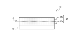
- FIG. 2 is a cross-sectional view of a negative electrode according to an embodiment of the present invention.
- the secondary battery 10 shown in FIG. 1 includes a wound electrode body 14 formed by winding a positive electrode 11 and a negative electrode 12 with a separator 13 therebetween, an electrolyte, insulating plates 18 and 19 arranged above and below the electrode body 14, and a battery case 15 for accommodating the above-mentioned components.
- the battery case 15 is composed of a cylindrical case body 16 with a bottom and a sealing body 17 that closes the opening of the case body 16.
- the wound electrode body 14 other types of electrode bodies may be used, such as a laminated electrode body in which positive and negative electrodes are alternately laminated with separators between them.
- the battery case 15 include a cylindrical, square, coin-shaped, button-shaped, or other metal case, and a resin case formed by laminating resin sheets (a so-called laminate type).
- the electrolyte may be an aqueous electrolyte, but is preferably a nonaqueous electrolyte containing a nonaqueous solvent and an electrolyte salt dissolved in the nonaqueous solvent.
- a nonaqueous electrolyte containing a nonaqueous solvent and an electrolyte salt dissolved in the nonaqueous solvent.
- esters, ethers, nitriles, amides, and mixed solvents of two or more of these are used as the nonaqueous solvent.
- nonaqueous solvents include ethylene carbonate (EC), ethyl methyl carbonate (EMC), dimethyl carbonate (DMC), diethyl carbonate (DEC), and mixed solvents of these.
- the nonaqueous solvent may contain a halogen-substituted product (e.g., fluoroethylene carbonate, etc.) in which at least a part of the hydrogen of these solvents is replaced with a halogen atom such as fluorine.
- a halogen-substituted product e.g., fluoroethylene carbonate, etc.
- a lithium salt such as LiPF 6 is used as the electrolyte salt.
- the case body 16 is, for example, a cylindrical metal container with a bottom.
- a gasket 28 is provided between the case body 16 and the sealing body 17 to ensure airtightness inside the battery.
- the case body 16 has a protruding portion 22 that supports the sealing body 17, for example, a part of the side surface that protrudes inward.
- the protruding portion 22 is preferably formed in an annular shape along the circumferential direction of the case body 16, and supports the sealing body 17 on its upper surface.
- the sealing body 17 has a structure in which, in order from the electrode body 14 side, a filter 23, a lower valve body 24, an insulating member 25, an upper valve body 26, and a cap 27 are stacked.
- Each member constituting the sealing body 17 has, for example, a disk or ring shape, and each member except the insulating member 25 is electrically connected to each other.
- the lower valve body 24 and the upper valve body 26 are connected to each other at their respective centers, and the insulating member 25 is interposed between each of their peripheral edges.
- the lower valve body 24 deforms and breaks so as to push the upper valve body 26 toward the cap 27, and the current path between the lower valve body 24 and the upper valve body 26 is interrupted.
- the upper valve body 26 breaks, and gas is discharged from the opening of the cap 27.
- the positive electrode lead 20 attached to the positive electrode 11 extends through a through hole in the insulating plate 18 toward the sealing body 17, and the negative electrode lead 21 attached to the negative electrode 12 extends through the outside of the insulating plate 19 toward the bottom side of the case body 16.
- the positive electrode lead 20 is connected by welding or the like to the underside of the filter 23, which is the bottom plate of the sealing body 17, and the cap 27, which is the top plate of the sealing body 17 and is electrically connected to the filter 23, serves as the positive electrode terminal.
- the negative electrode lead 21 is connected by welding or the like to the inner bottom surface of the case body 16, and the case body 16 serves as the negative electrode terminal.
- the positive electrode 11, negative electrode 12, and separator 13 are described in detail below.
- the positive electrode 11 has a positive electrode current collector and a positive electrode composite layer disposed on the positive electrode current collector.
- the positive electrode composite layer may be disposed on one side of the positive electrode current collector, or on both sides of the positive electrode current collector.
- a foil of a metal such as aluminum that is stable in the potential range of the positive electrode 11, or a film having the metal disposed on the surface layer can be used.
- the positive electrode composite layer is composed of, for example, a positive electrode active material, a binder, a conductive material, and the like.
- the positive electrode 11 can be produced, for example, by applying a positive electrode slurry containing a positive electrode active material, a binder, a conductive material, and the like to the surface of the positive electrode current collector, drying the coating, and then rolling to form a positive electrode composite layer on both sides of the positive electrode current collector.
- Conductive materials contained in the positive electrode composite layer include carbon materials such as carbon black, acetylene black, ketjen black, graphite, and carbon nanotubes. Binders contained in the positive electrode composite layer include fluororesins such as polytetrafluoroethylene (PTFE) and polyvinylidene fluoride (PVdF), polyacrylonitrile (PAN), polyimide, acrylic resin, polyolefin, styrene-butadiene rubber (SBR), cellulose derivatives such as carboxymethylcellulose (CMC) or its salts, and polyethylene oxide (PEO).
- fluororesins such as polytetrafluoroethylene (PTFE) and polyvinylidene fluoride (PVdF), polyacrylonitrile (PAN), polyimide, acrylic resin, polyolefin, styrene-butadiene rubber (SBR), cellulose derivatives such as carboxymethylcellulose (CMC) or its salts, and polyethylene oxide (PEO).
- lithium transition metal composite oxides and the like are used as the positive electrode active material.
- metal elements contained in the lithium transition metal composite oxide include Ni, Co, Mn, Al, B, Mg, Ti, V, Cr, Fe, Cu, Zn, Ga, Sr, Zr, Nb, In, Sn, Ta, W, and the like.
- An example of a suitable lithium transition metal composite oxide is a composite oxide represented by the general formula LiMO 2 (M is Ni and X, X is a metal element other than Ni, and the proportion of Ni is 50 mol% or more and 95 mol% or less with respect to the total mole number of metal elements other than Li).
- X in the above formula is, for example, Co, Mn, Al, B, Mg, Ti, V, Cr, Fe, Cu, Zn, Ga, Sr, Zr, Nb, In, Sn, Ta, W, and the like.
- FIG. 2 is a cross-sectional view of a negative electrode according to an embodiment.
- the negative electrode 12 has a negative electrode current collector 40 and a negative electrode composite layer 42 provided on the negative electrode current collector 40.
- the negative electrode composite layer 42 is provided on one side of the negative electrode current collector 40, but the negative electrode composite layer 42 may be provided on both sides of the negative electrode current collector 40.
- the negative electrode current collector 40 may be a foil of a metal such as copper that is stable in the potential range of the negative electrode 12, or a film in which the metal is disposed on the surface layer.
- the negative electrode composite layer 42 includes a negative electrode active material, and may include a binder, a conductive material, and the like.
- the negative electrode active material includes a carbon material and a Si-based material.
- the negative electrode active material may include a material that can reversibly absorb and release lithium ions.
- the binder and conductive material may be the same as those in the case of the positive electrode 11.
- the pore size distribution of the negative electrode mixture layer 42 measured by mercury porosimetry has a peak R1 having a maximum value V R1 in the range of pore size of 1 ⁇ m or more and 3 ⁇ m or less, and a peak R2 having a maximum value V R2 in the range of pore size of 30 ⁇ m or more and 100 ⁇ m or less, and the ratio (V R2 /V R1 ) of the maximum value V R2 of the peak R2 to the maximum value V R1 of the peak R1 is 0.5 to 100, preferably 0.5 to 100, more preferably 0.5 to 1.0.
- the ratio (V R2 /V R1 ) of the maximum value V R2 of the peak R2 to the maximum value V R1 of the peak R1 in the pore size distribution satisfies the above range, thereby enhancing the permeability of the electrolyte into the negative electrode mixture layer 42. That is, the negative electrode 12 has good permeability of the electrolyte.
- the pore size distribution of negative electrode mixture layer 42 measured by mercury porosimetry preferably further has peak R3 having a maximum value V R3 in the pore size range of 0.1 ⁇ m to 0.6 ⁇ m, and the ratio (V R3 /V R1 ) of the maximum value V R3 of peak R3 to the maximum value V R1 of peak R1 is 0.9 to 1.5.
- the ratio (V R3 /V R1 ) of the maximum value V R3 of peak R3 to the maximum value V R1 of peak R1 satisfies the above range, for example, the permeability of the electrolyte into negative electrode mixture layer 42 is further increased.
- mercury intrusion method mercury is pressurized to cause it to penetrate into the pores of a solid sample, and the diameter and volume of the pores are calculated from the pressure applied to the mercury and the amount of mercury pressed into the pores.
- the diameter D of the pore is calculated from the pressure P, the contact angle ⁇ of the mercury, and the surface tension ⁇ of the mercury according to the following formula.
- the pore volume is also calculated from the amount of mercury pressed into the pores.
- the pore size distribution measured by mercury intrusion porosimetry is a graph (pore distribution curve) in which the log differential pore volume ( cm3 /g) is plotted against the average pore diameter ( ⁇ m) at each measurement point, with the horizontal axis representing the pore diameter ( ⁇ m) and the vertical axis representing the log differential pore volume ( cm3 /g).
- the maximum value of the peak in the pore size distribution means the value of the log differential pore volume at the apex of the peak.
- Pore size distribution measurement by mercury porosimetry is performed on the negative electrode composite layer before initial charging.
- a measurement sample obtained by punching out the negative electrode into a specified shape before initial charging can be used to measure the pore size distribution of the negative electrode composite layer of the measurement sample by mercury porosimetry.
- the measurement sample only needs to have at least the negative electrode composite layer on its surface, and may also have other components such as a negative electrode current collector.
- the measurement of pore size distribution by mercury intrusion porosimetry can be carried out using an apparatus such as the Autopore IV9500 series manufactured by Micromeltix.
- the measurement sample is sealed in a sample container in an inert atmosphere, and mercury is injected into the sample container to apply pressure to the mercury.
- the pressure applied to the mercury is adjusted appropriately according to the size of the pore size that the measurement sample may have, and is not particularly limited, but it is preferable to change the pressure from 0.5 psi (3.4 kPa) to 60,000 psi (413,400 kPa) to measure, since this allows the pore size to be measured over a wide range.
- the ratio of pores corresponding to peak R2 in the upper half region 42b is greater than the ratio of pores corresponding to peak R2 in the lower half region 42a.
- Dividing the negative electrode mixture layer 42 into two equal parts in the thickness direction means that when the stacking direction of the negative electrode current collector 40 and the negative electrode mixture layer 42 is the thickness direction of the negative electrode mixture layer 42, the negative electrode mixture layer 42 is divided into two equal parts at the middle Z of the thickness of the negative electrode mixture layer 42.
- the negative electrode mixture layer 42 is divided into two equal parts in the thickness direction, with the negative electrode mixture layer 42 located closer to the negative electrode current collector 40 being the lower half region 42a, and the negative electrode mixture layer 42 located further from the negative electrode current collector 40 being the upper half region 42b.
- the proportion of pores corresponding to peak R2 is measured as follows.
- the Si-based material contained in the negative electrode active material may be, for example, Si, a Si alloy, or a Si compound.
- the Si-based material may also be, for example, a composite particle containing an ion-conducting phase and a silicon phase (silicon particles in one respect) dispersed within the ion-conducting phase.
- the ion-conducting phase is a phase that conducts ions, and may be, for example, a silicate phase, a carbon phase, or a silicon oxide phase.
- the carbon phase may be composed of, for example, amorphous carbon.
- amorphous carbon examples include hard carbon, soft carbon, and other amorphous carbon.
- Amorphous carbon is a carbon material having an average interplanar spacing d 002 of the (002) planes measured by an X-ray diffraction method of more than 0.34 nm.
- the main component of the silicon oxide phase may be silicon dioxide.
- the composition of the composite particle including the silicon oxide phase and the silicon phase dispersed therein can be expressed as SiOx as a whole.
- SiOx has a structure in which silicon particles are dispersed in amorphous SiO2 .
- the content ratio x of oxygen to silicon is, for example, preferably 0.5 ⁇ x ⁇ 2.0, more preferably 0.8 ⁇ x ⁇ 1.5.
- the silicate phase may satisfy the following conditions (1) and/or (2).
- the silicate phase contains at least one element selected from the group consisting of alkali metal elements and Group 2 elements (Group 2 elements of the long form periodic table).
- the silicate phase contains an element L.
- the element L is at least one selected from the group consisting of B, Al, Zr, Nb, Ta, V, lanthanoids, Y, Ti, P, Bi, Zn, Sn, Pb, Sb, Co, Er, F, and W.
- Lanthanoids is a general term for 15 elements ranging from lanthanum (La) with atomic number 57 to lutetium (Lu) with atomic number 71.
- examples of alkali metal elements include lithium (Li), potassium (K), and sodium (Na).
- Examples of Group 2 elements include magnesium (Mg), calcium (Ca), strontium (Sr), and barium (Ba).
- a silicate phase containing lithium hereinafter, may be referred to as "lithium silicate phase" is preferable in that it has, for example, a small irreversible capacity and a high initial charge/discharge efficiency.
- the lithium silicate phase may be an oxide phase containing Li, Si, and O, and may contain other elements.
- the atomic ratio of O to Si in the lithium silicate phase: O/Si is, for example, greater than 2 and less than 4.
- O/Si is greater than 2 and less than 3.
- the atomic ratio of Li to Si in the lithium silicate phase: Li/Si is, for example, greater than 0 and less than 4.
- the Si-based material may also include composite particles containing an ion-conducting phase and a silicon phase dispersed within the ion-conducting phase, and a coating layer covering at least a portion of the surface of the composite particles.
- the coating layer present on the surface of the composite particle includes, for example, a conductive layer.
- a conductive layer By forming a conductive layer on the surface of the composite particle, the conductivity of the Si-based material may be increased.
- the conductive material constituting the conductive layer is preferably a conductive material containing carbon.
- conductive materials containing carbon include conductive carbon materials.
- conductive carbon materials include carbon black, graphite, amorphous carbon (amorphous carbon) with low crystallinity, etc.
- Amorphous carbon is preferable because it has a large buffering effect on the silicon phase that changes in volume during charging and discharging.
- the amorphous carbon may be easily graphitized carbon (soft carbon) or difficult to graphitize carbon (hard carbon).
- the thickness of the conductive layer may be, for example, in the range of 1 to 200 nm.
- the thickness of the conductive layer can be measured by observing the cross section of the Si-containing material using a SEM or TEM (transmission electron microscope).
- the content of the Si-based material is preferably 30% by mass or more relative to the total amount of the negative electrode active material, in terms of increasing the capacity of the secondary battery, etc. Also, in terms of increasing the capacity of the secondary battery and suppressing swelling of the negative electrode, the content of the Si-based material is preferably 30% by mass or more and 60% by mass or less relative to the total amount of the negative electrode active material, and more preferably 35% by mass or more and 55% by mass or less.
- the average particle size of the Si-based material is preferably 3 ⁇ m or more and 15 ⁇ m or less, more preferably 4 ⁇ m or more and 12 ⁇ m or less, and even more preferably 6 ⁇ m or more and 10 ⁇ m or less, in order to suppress deterioration of the charge-discharge cycle characteristics.
- the average particle size is the volume average particle size D50, which is the volume accumulated value of 50% in the particle size distribution obtained by the laser diffraction scattering method.
- the carbon material contained in the negative electrode active material may be a conventionally known carbon material used as a negative electrode active material in secondary batteries, and examples of such graphite materials include natural graphite such as flake graphite, lump graphite, and earthy graphite, and artificial graphite such as lump artificial graphite (MAG) and graphitized mesophase carbon microbeads (MCMB).
- natural graphite such as flake graphite, lump graphite, and earthy graphite
- artificial graphite such as lump artificial graphite (MAG) and graphitized mesophase carbon microbeads (MCMB).
- the carbon material preferably includes a graphite material having a specific surface area of 3 m 2 /g or less.
- a graphite material having a specific surface area of 3 m 2 /g or less is included in the negative electrode mixture layer 42, for example, pores corresponding to the peak R2 are easily formed in the negative electrode mixture layer 42, and the permeability of the electrolyte to the negative electrode mixture layer 42 is further improved.
- the specific surface area of the graphite material is preferably 0.5 m 2 /g or more.
- the specific surface area of the graphite material is more preferably 0.5 m 2 /g or more and 2.0 m 2 /g or less.
- the specific surface area of the graphite material is measured by the BET method using a conventionally known specific surface area measuring device (for example, Macsorb (registered trademark) HM model-1201 manufactured by Mountec Co., Ltd.).
- the average particle size of the graphite material is preferably 5 ⁇ m or more and 30 ⁇ m or less, more preferably 10 ⁇ m or more and 25 ⁇ m or less, and even more preferably 12 ⁇ m or more and 20 ⁇ m or less, in order to suppress swelling of the negative electrode, for example.
- the average particle size is the volume average particle size D50 as described above.
- the content of the carbon material is, for example, preferably 40% by mass or more and 70% by mass or less, and more preferably 45% by mass or more and 65% by mass or less, relative to the total amount of the negative electrode active material.
- the negative electrode 12 has a first step of applying a negative electrode active material containing a carbon material and a Si-based material, vaporized particles that vaporize at a temperature of 100°C to 200°C, and a negative electrode slurry containing a binder and the like that is added as necessary to a negative electrode current collector 40 to form a coating film, and then rolling the coating film. After the first step, the coating film is heat-treated at a temperature of 100°C to 200°C to form a negative electrode composite layer 42.
- the vaporized particles are vaporized and released from the coating film, so that not only small pores corresponding to the peaks R1 and R3 but also relatively large pores corresponding to the peak R2 are formed in the coating film.
- the carbon material it is preferable to use graphite particles having a specific surface area of 3 m 2 /g or less. Since graphite particles having a specific surface area of 3 m 2 /g or less are hard materials, for example, even if the coating film is rolled, the graphite particles are not easily crushed and the pores in the coating film are easily maintained. According to the above manufacturing method, it is easy to obtain the negative electrode mixture layer 42 having the above-mentioned pore size distribution.
- the heat treatment time should be long enough to allow the vapor particles in the coating to vaporize, for example, 5 hours or more.
- the vaporized particles include at least one of the following: a material that sublimes at a temperature of 100°C or more and 200°C or less; a material that decomposes at a temperature of 100°C or more and 200°C or less; and a material that melts and then vaporizes at a temperature of 100°C or more and 200°C or less.
- Specific materials include, for example, dicarboxylic acids such as fumaric acid, malonic acid, and malic acid, metal oxalates, camphor, and naphthalene.
- the volume average particle size of the vaporized particles is preferably 2 ⁇ m or more and 10 ⁇ m or less, for example, in that relatively large pores corresponding to the above peak R2 are easily formed.
- the raw materials such as the negative electrode active material and vaporized particles can be mixed using, for example, a cutter mill, a pin mill, a bead mill, a microparticle compounder (a device that generates shear force between a specially shaped rotor that rotates at high speed inside a tank and a collision plate), a granulator, or a kneader such as a twin-screw extrusion kneader or planetary mixer.
- a cutter mill a pin mill, a bead mill, a microparticle compounder (a device that generates shear force between a specially shaped rotor that rotates at high speed inside a tank and a collision plate), a granulator, or a kneader such as a twin-screw extrusion kneader or planetary mixer.
- a microparticle compounder a device that generates shear force between a specially shaped rotor that rotates at high speed inside a
- the negative electrode slurry can be applied using, for example, a slit die coater, reverse roll coater, lip coater, blade coater, knife coater, gravure coater, or dip coater.
- the temperature for heating and drying may be a temperature at which the vaporized particles do not vaporize, or a temperature at which some of the vaporized particles vaporize.
- the coating can be rolled several times at a specified line pressure using, for example, a roll press until the coating reaches the specified thickness.
- the ratio of the maximum value V R2 of peak R2 to the maximum value V R1 of peak R1 in the pore size distribution of the negative electrode composite layer 42 (V R2 /V R1 ) and the ratio of the maximum value V R3 of peak R3 to the maximum value V R1 of peak R1 (V R1 /V R3 ) can be controlled by adjusting, for example, the specific surface area of the graphite particles, the volume average particle size of the vaporized particles, the viscosity of the negative electrode slurry due to the addition of a solvent, etc., the heat treatment time and temperature, the linear pressure during coating rolling, etc.
- a negative electrode slurry A containing a carbon material and vaporized particles, and a negative electrode slurry B containing a carbon material and vaporized particles (which may not contain vaporized particles) having a lower concentration than the negative electrode slurry A may be prepared, and two-layer coating of the negative electrode slurries A and B may be performed on the negative electrode current collector 40.
- the negative electrode slurry B is coated on the negative electrode current collector 40 to prepare a coating film of the negative electrode slurry B, and then the negative electrode slurry A is coated on the coating film to prepare a coating film of the negative electrode slurry A.
- graphite particles having a specific surface area of 3 m 2 /g or less as the carbon material contained in at least the negative electrode slurry A among the carbon materials contained in the negative electrode slurries A and B.
- two-layer coating for example, it becomes easy to make the abundance ratio of pores corresponding to the peak R2 in the upper half region 42b of the negative electrode mixture layer 42 larger than the abundance ratio of pores corresponding to the peak R2 in the lower half region 42a.
- a porous sheet having ion permeability and insulating properties is used for the separator 13.
- the porous sheet include a microporous thin film, a woven fabric, and a nonwoven fabric.
- Suitable materials for the separator 13 include polyolefins such as polyethylene and polypropylene, and cellulose.
- the separator 13 may have either a single-layer structure or a laminated structure. A heat-resistant layer or the like may be formed on the surface of the separator.
- Example> [Preparation of negative electrode] A graphite material with a specific surface area of 1.2 m 2 /g and SiO were mixed in a mass ratio of 90:10. This mixture was used as the negative electrode active material. Then, the mass ratio of the negative electrode active material: carboxymethyl cellulose (CMC): styrene-butadiene copolymer rubber (SBR): carbon nanotubes: fumaric acid (average particle size 6 ⁇ m) was mixed to be 100:1:1:1:12.5, and mixed with any water to prepare a negative electrode slurry. This negative electrode slurry was applied to both sides of a negative electrode current collector made of copper foil, and after drying the coating, the coating was rolled with a rolling roller. Thereafter, the coating was heat-treated at 200° C. for 5 hours to produce a negative electrode in which a negative electrode mixture layer was formed on both sides of the negative electrode current collector.
- CMC carboxymethyl cellulose
- SBR styrene-butadiene cop
- the pore size distribution of the negative electrode composite layer of the obtained negative electrode was measured by mercury intrusion porosimetry, and a peak R1 having a maximum value (V R1 : 0.087 cm 3 /g) at a pore diameter of 1.62 ⁇ m, a peak R2 having a maximum value (V R2 : 0.069 cm 3 /g) at a pore diameter of 45.2 ⁇ m, and a peak R3 having a maximum value (V R3 : 0.084) at a pore diameter of 0.183 ⁇ m were observed.
- V R2 /V R1 was 0.786
- V R3 /V R1 was 0.961.
- a negative electrode was prepared in the same manner as in the examples, except that fumaric acid was not used.
- the pore size distribution of the negative electrode composite layer was measured by mercury intrusion porosimetry, and a peak R1 having a maximum value (V R1 : 0.098 cm 3 /g) at a pore diameter of 1.33 ⁇ m, a peak R2 having a maximum value (V R2 : 0.047 cm 3 /g) at a pore diameter of 60.3 ⁇ m, and a peak R3 having a maximum value (V R3 : 0.094) at a pore diameter of 0.227 ⁇ m were observed.
- V R2 /V R1 was 0.484
- V R3 /V R1 was 0.959.
- a negative electrode was prepared in the same manner as in the Example, except that fumaric acid was not used and the linear pressure during rolling of the coating film by the rolling roller was 10% lower than that in the Example.
- the pore size distribution of the negative electrode mixture layer was measured by mercury intrusion porosimetry, and a peak R1 having a maximum value (V R1 : 0.099 cm 3 /g) at a pore diameter of 1.62 ⁇ m, a peak R2 having a maximum value (V R2 : 0.034 cm 3 /g) at a pore diameter of 90.5 ⁇ m, and a peak R3 having a maximum value (V R3 : 0.130) at a pore diameter of 0.350 ⁇ m were observed.
- V R2 /V R1 was 0.339
- V R3 /V R1 was 1.305.
- a negative electrode was prepared in the same manner as in the example, except that fumaric acid was not used and a graphite material with a specific surface area of 0.9 m 2 /g was used.
- the pore size distribution of the negative electrode composite layer was measured by mercury intrusion porosimetry, and a peak R1 having a maximum value (V R1 : 0.171 cm 3 /g) at a pore diameter of 1.17 ⁇ m, a peak R2 having a maximum value (V R2 : 0.026 cm 3 /g) at a pore diameter of 72.1 ⁇ m, and a peak R3 having a maximum value (V R3 : 0.177) at a pore diameter of 0.406 ⁇ m were observed.
- V R2 /V R1 was 0.154
- V R3 /V R1 was 1.035.
- a negative electrode was prepared in the same manner as in the example, except that a graphite material with a specific surface area of 4.0 m 2 /g was used.
- the pore size distribution of the negative electrode composite layer was measured by mercury intrusion porosimetry, and a peak R1 having a maximum value (V R1 : 0.356 cm 3 /g) at a pore diameter of 1.05 ⁇ m, a peak R2 having a maximum value (V R2 : 0.043 cm 3 /g) at a pore diameter of 47.9 ⁇ m, and a peak R3 having a maximum value (V R3 : 0.065) at a pore diameter of 0.128 ⁇ m were observed.
- V R2 /V R1 was 0.120
- V R3 /V R1 was 0.182.
- the Examples had a shorter liquid absorption time than Comparative Examples 1 to 4. That is, in a negative electrode mixture layer containing a carbon material and a Si-based material, the pore size distribution measured by mercury porosimetry has a peak R1 having a maximum value V R1 in the pore size range of 1 ⁇ m or more and 3 ⁇ m or less, and a peak R2 having a maximum value V R2 in the pore size range of 30 ⁇ m or more and 100 ⁇ m or less, and the ratio (V R2 /V R1 ) of the maximum value V R2 of the peak R2 to the maximum value V R1 of the peak R1 is 0.5 or more, so that a negative electrode with good electrolyte permeability can be obtained.
- a negative electrode current collector and a negative electrode mixture layer provided on the negative electrode current collector,
- the negative electrode mixture layer contains a carbon material and a Si-based material, a pore size distribution of the negative electrode composite layer measured by mercury intrusion porosimetry has a peak R1 having a maximum value V R1 in a pore size range of 1 ⁇ m or more and 3 ⁇ m or less, and a peak R2 having a maximum value V R2 in a pore size range of 30 ⁇ m or more and 100 ⁇ m or less, and a ratio (V R2 /V R1 ) of the maximum value V R2 of the peak R2 to the maximum value V R1 of the peak R1 is 0.5 or more and 100 or less.
- the negative electrode for a secondary battery according to any one of (1) to (3) wherein the pore size distribution of the negative electrode mixture layer has a peak R3 having a maximum value V R3 in a pore size range of 0.1 ⁇ m to 0.6 ⁇ m, and the ratio (V R3 /V R1 ) of the maximum value V R3 of the peak R3 to the maximum value V R1 of the peak R1 is 0.9 to 1.5.
- the Si-based material includes composite particles having an ion-conducting phase and a silicon phase dispersed in the ion-conducting phase.
Landscapes
- Chemical & Material Sciences (AREA)
- Engineering & Computer Science (AREA)
- Chemical Kinetics & Catalysis (AREA)
- Electrochemistry (AREA)
- General Chemical & Material Sciences (AREA)
- Materials Engineering (AREA)
- Manufacturing & Machinery (AREA)
- Composite Materials (AREA)
- Inorganic Chemistry (AREA)
- Battery Electrode And Active Subsutance (AREA)
- Secondary Cells (AREA)
Priority Applications (3)
| Application Number | Priority Date | Filing Date | Title |
|---|---|---|---|
| CN202480029230.2A CN121039825A (zh) | 2023-05-24 | 2024-05-20 | 二次电池用负极、二次电池及二次电池用负极的制造方法 |
| JP2025522398A JPWO2024242077A1 (https=) | 2023-05-24 | 2024-05-20 | |
| EP24811084.3A EP4723185A1 (en) | 2023-05-24 | 2024-05-20 | Negative electrode for secondary batteries, secondary battery, and method for producing negative electrode for secondary batteries |
Applications Claiming Priority (2)
| Application Number | Priority Date | Filing Date | Title |
|---|---|---|---|
| JP2023-085648 | 2023-05-24 | ||
| JP2023085648 | 2023-05-24 |
Publications (1)
| Publication Number | Publication Date |
|---|---|
| WO2024242077A1 true WO2024242077A1 (ja) | 2024-11-28 |
Family
ID=93589861
Family Applications (1)
| Application Number | Title | Priority Date | Filing Date |
|---|---|---|---|
| PCT/JP2024/018556 Ceased WO2024242077A1 (ja) | 2023-05-24 | 2024-05-20 | 二次電池用負極、二次電池、及び二次電池用負極の製造方法 |
Country Status (4)
| Country | Link |
|---|---|
| EP (1) | EP4723185A1 (https=) |
| JP (1) | JPWO2024242077A1 (https=) |
| CN (1) | CN121039825A (https=) |
| WO (1) | WO2024242077A1 (https=) |
Citations (4)
| Publication number | Priority date | Publication date | Assignee | Title |
|---|---|---|---|---|
| JP2001210323A (ja) | 2000-01-26 | 2001-08-03 | Matsushita Electric Ind Co Ltd | 非水電解質二次電池 |
| JP2013219059A (ja) | 2013-07-30 | 2013-10-24 | Sumitomo Bakelite Co Ltd | リチウムイオン二次電池用負極活物質、リチウムイオン二次電池用負極合剤、リチウムイオン二次電池用負極、及びリチウムイオン二次電池 |
| WO2022230661A1 (ja) * | 2021-04-26 | 2022-11-03 | パナソニックIpマネジメント株式会社 | 二次電池用負極、二次電池、及び二次電池用負極の製造方法 |
| WO2023032558A1 (ja) * | 2021-08-31 | 2023-03-09 | パナソニックホールディングス株式会社 | 二次電池用負極および二次電池 |
-
2024
- 2024-05-20 JP JP2025522398A patent/JPWO2024242077A1/ja active Pending
- 2024-05-20 WO PCT/JP2024/018556 patent/WO2024242077A1/ja not_active Ceased
- 2024-05-20 CN CN202480029230.2A patent/CN121039825A/zh active Pending
- 2024-05-20 EP EP24811084.3A patent/EP4723185A1/en active Pending
Patent Citations (4)
| Publication number | Priority date | Publication date | Assignee | Title |
|---|---|---|---|---|
| JP2001210323A (ja) | 2000-01-26 | 2001-08-03 | Matsushita Electric Ind Co Ltd | 非水電解質二次電池 |
| JP2013219059A (ja) | 2013-07-30 | 2013-10-24 | Sumitomo Bakelite Co Ltd | リチウムイオン二次電池用負極活物質、リチウムイオン二次電池用負極合剤、リチウムイオン二次電池用負極、及びリチウムイオン二次電池 |
| WO2022230661A1 (ja) * | 2021-04-26 | 2022-11-03 | パナソニックIpマネジメント株式会社 | 二次電池用負極、二次電池、及び二次電池用負極の製造方法 |
| WO2023032558A1 (ja) * | 2021-08-31 | 2023-03-09 | パナソニックホールディングス株式会社 | 二次電池用負極および二次電池 |
Also Published As
| Publication number | Publication date |
|---|---|
| EP4723185A1 (en) | 2026-04-08 |
| JPWO2024242077A1 (https=) | 2024-11-28 |
| CN121039825A (zh) | 2025-11-28 |
Similar Documents
| Publication | Publication Date | Title |
|---|---|---|
| JP7716670B2 (ja) | リチウムイオン二次電池用負極およびリチウムイオン二次電池 | |
| JP7531165B2 (ja) | リチウムイオン二次電池用負極及びリチウムイオン二次電池 | |
| JP7756326B2 (ja) | 二次電池用負極、二次電池、及び二次電池用負極の製造方法 | |
| JP7836961B2 (ja) | 二次電池用負極活物質および二次電池 | |
| US20240396018A1 (en) | Negative electrode for secondary batteries, and secondary battery | |
| JP2014011093A (ja) | 負極材、リチウムイオン二次電池用負極、リチウムイオン二次電池およびそれらの製造方法 | |
| JP7668469B2 (ja) | 非水電解質二次電池用負極、及び非水電解質二次電池 | |
| WO2024048183A1 (ja) | 二次電池用負極、二次電池、及び二次電池用負極の製造方法 | |
| WO2024090206A1 (ja) | 二次電池用負極及び二次電池 | |
| WO2024070259A1 (ja) | 非水電解質二次電池 | |
| JP7720569B2 (ja) | リチウムイオン電池 | |
| WO2024042897A1 (ja) | 二次電池用負極および非水電解質二次電池 | |
| WO2024070220A1 (ja) | 非水電解質二次電池 | |
| WO2024242077A1 (ja) | 二次電池用負極、二次電池、及び二次電池用負極の製造方法 | |
| WO2024042888A1 (ja) | 非水電解質二次電池 | |
| WO2023145540A1 (ja) | 非水電解質二次電池用負極活物質、負極及び非水電解質二次電池 | |
| WO2023162961A1 (ja) | 二次電池用負極及び二次電池 | |
| JP2017103137A (ja) | リチウムイオン二次電池用負極活物質、リチウムイオン二次電池用負極及びリチウムイオン二次電池 | |
| WO2025062937A1 (ja) | 二次電池 | |
| WO2024176815A1 (ja) | 二次電池用負極、二次電池、及び二次電池用負極の製造方法 | |
| WO2023181912A1 (ja) | 非水電解質二次電池用正極および非水電解質二次電池 | |
| WO2024247965A1 (ja) | 非水電解質二次電池 | |
| WO2024090148A1 (ja) | 非水電解質二次電池 | |
| WO2024106074A1 (ja) | 非水電解質二次電池 | |
| WO2024247945A1 (ja) | 非水電解質二次電池 |
Legal Events
| Date | Code | Title | Description |
|---|---|---|---|
| 121 | Ep: the epo has been informed by wipo that ep was designated in this application |
Ref document number: 24811084 Country of ref document: EP Kind code of ref document: A1 |
|
| ENP | Entry into the national phase |
Ref document number: 2025522398 Country of ref document: JP Kind code of ref document: A |
|
| WWE | Wipo information: entry into national phase |
Ref document number: 2025522398 Country of ref document: JP |
|
| NENP | Non-entry into the national phase |
Ref country code: DE |
|
| WWE | Wipo information: entry into national phase |
Ref document number: 2024811084 Country of ref document: EP |
|
| ENP | Entry into the national phase |
Ref document number: 2024811084 Country of ref document: EP Effective date: 20260102 |
|
| ENP | Entry into the national phase |
Ref document number: 2024811084 Country of ref document: EP Effective date: 20260102 |
|
| ENP | Entry into the national phase |
Ref document number: 2024811084 Country of ref document: EP Effective date: 20260102 |
|
| ENP | Entry into the national phase |
Ref document number: 2024811084 Country of ref document: EP Effective date: 20260102 |
|
| ENP | Entry into the national phase |
Ref document number: 2024811084 Country of ref document: EP Effective date: 20260102 |
|
| ENP | Entry into the national phase |
Ref document number: 2024811084 Country of ref document: EP Effective date: 20260102 |
|
| WWP | Wipo information: published in national office |
Ref document number: 2024811084 Country of ref document: EP |