WO2024241921A1 - 自動分析装置 - Google Patents
自動分析装置 Download PDFInfo
- Publication number
- WO2024241921A1 WO2024241921A1 PCT/JP2024/017482 JP2024017482W WO2024241921A1 WO 2024241921 A1 WO2024241921 A1 WO 2024241921A1 JP 2024017482 W JP2024017482 W JP 2024017482W WO 2024241921 A1 WO2024241921 A1 WO 2024241921A1
- Authority
- WO
- WIPO (PCT)
- Prior art keywords
- reagent
- predetermined amount
- amount
- automatic analyzer
- analyzer according
- Prior art date
- Legal status (The legal status is an assumption and is not a legal conclusion. Google has not performed a legal analysis and makes no representation as to the accuracy of the status listed.)
- Ceased
Links
Images





Classifications
-
- G—PHYSICS
- G01—MEASURING; TESTING
- G01N—INVESTIGATING OR ANALYSING MATERIALS BY DETERMINING THEIR CHEMICAL OR PHYSICAL PROPERTIES
- G01N35/00—Automatic analysis not limited to methods or materials provided for in any single one of groups G01N1/00 - G01N33/00; Handling materials therefor
- G01N35/10—Devices for transferring samples or any liquids to, in, or from, the analysis apparatus, e.g. suction devices, injection devices
- G01N35/1009—Characterised by arrangements for controlling the aspiration or dispense of liquids
- G01N35/1016—Control of the volume dispensed or introduced
-
- G—PHYSICS
- G01—MEASURING; TESTING
- G01N—INVESTIGATING OR ANALYSING MATERIALS BY DETERMINING THEIR CHEMICAL OR PHYSICAL PROPERTIES
- G01N1/00—Sampling; Preparing specimens for investigation
-
- G—PHYSICS
- G01—MEASURING; TESTING
- G01N—INVESTIGATING OR ANALYSING MATERIALS BY DETERMINING THEIR CHEMICAL OR PHYSICAL PROPERTIES
- G01N35/00—Automatic analysis not limited to methods or materials provided for in any single one of groups G01N1/00 - G01N33/00; Handling materials therefor
- G01N35/10—Devices for transferring samples or any liquids to, in, or from, the analysis apparatus, e.g. suction devices, injection devices
- G01N35/1004—Cleaning sample transfer devices
Definitions
- the present invention relates to an automatic analyzer.
- Patent Document 1 discloses a technology that detects abnormalities in dispensing by comparing the difference between the pressure sensor output immediately before the start of the aspiration operation and the pressure sensor output during the aspiration operation with a threshold value (pressure threshold value).
- the present invention was made in consideration of these problems, and its purpose is to provide an automatic analyzer that can accurately detect abnormalities during aspiration even when the amount of reagent used in the analysis is small.
- the present invention provides an automatic analyzer that includes a dispensing mechanism that dispenses a reagent from a reagent container to a reaction container, a control unit that controls the dispensing mechanism to aspirate an amount of the reagent including at least a second predetermined amount in addition to a first predetermined amount used for analysis, and then dispense the second predetermined amount of the reagent into the reagent container, and then dispense the first predetermined amount of the reagent into the reaction container, and a pressure sensor that measures the pressure in the dispensing mechanism, and the control unit determines whether the reagent has been normally aspirated based on the measurement value of the pressure sensor when the dispensing mechanism aspirates the reagent, wherein when the first predetermined amount is equal to or greater than a predetermined first predetermined amount threshold, the second predetermined amount is a constant value regardless of the first predetermined amount, and when the first predetermined amount is less than the first predetermined amount threshold, the
- the present invention makes it possible to provide an automatic analyzer that can accurately detect abnormalities during suction even when the amount of reagent used in the analysis is small.
- FIG. 1 is a diagram illustrating an overall configuration of an automatic analyzer.
- FIG. 2 is a diagram illustrating a flow path configuration and reagent bottles of a reagent dispensing mechanism.
- FIG. 4 is a diagram showing an example of an operational sequence for dispensing a reagent.
- 11 is a flowchart showing a method for determining whether or not the nozzle is empty.
- 10 is a flowchart showing a method for adjusting the amount of reagent aspirated.
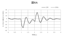
- FIG. 13 is a diagram showing an example (comparative example) in which the amount of reagent aspirated was not adjusted.
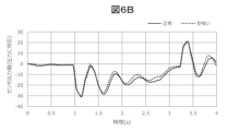
- FIG. 13 is a diagram showing an example (embodiment) of adjusting the amount of reagent aspirated.
- FIG. 13 is a diagram showing an example of a method for setting a pressure threshold value for determining dry suction.
- the automatic analyzer is an apparatus that dispenses samples such as blood or urine and reagents into reaction containers 2, causes a reaction, and measures the reacted liquid.
- Fig. 1 is a diagram showing a schematic overall configuration of the automatic analyzer. As shown in Fig. 1, the automatic analyzer is composed of a sample transport mechanism 8, a reagent disk 3, a reaction disk 1, a sample dispensing mechanism 9, reagent dispensing mechanisms 11 and 13, stirring mechanisms 17 and 18, a cleaning mechanism 15, a control unit 24, etc.
- Reaction vessels 2 are arranged in a circular pattern on the reaction disk 1.
- the reaction vessels 2 are containers for containing a mixed liquid of a sample and a reagent, and multiple reaction vessels 2 are arranged on the reaction disk 1.
- a sample transport mechanism 8 is located near the reaction disk 1, and transports a sample rack 7 carrying multiple sample vessels 6 containing samples to be analyzed.
- the reaction vessels 2 are immersed in a reaction tank filled with a thermally conductive medium (e.g., constant temperature water) whose temperature is controlled at, for example, 37 degrees, and the temperature of the reaction vessels 2 is always kept at 37 degrees by circulating the constant temperature water within the reaction tank.
- a thermally conductive medium e.g., constant temperature water
- the reagent disk 3 can hold multiple reagent bottles 4 (reagent containers) containing the reagents used in the analysis on its circumference, and also functions as a cooler that keeps the reagent bottles 4 cool.
- a sample dispensing mechanism 9 for dispensing a sample from a sample container 6 to a reaction container 2 is disposed between the reaction disk 1 and the sample transport mechanism 8.
- the sample dispensing mechanism 9 has a sample nozzle 10 that can rotate horizontally and move vertically, and the tip of which faces downward.
- a cleaning tank 19 for cleaning the sample nozzle 10 with cleaning water is disposed within the operating range of the sample dispensing mechanism 9.
- reagent dispensing mechanisms 11 and 13 for dispensing a reagent from a reagent bottle 4 to a reaction container 2 are disposed between the reaction disk 1 and the reagent disk 3.
- the reagent dispensing mechanisms 11 and 13 have reagent nozzles 12 and 14 that can rotate horizontally and move vertically, and the tip of which faces downward.
- Cleaning tanks 20 and 21 for cleaning the reagent nozzles 12 and 14 with cleaning water are disposed within the operating range of the reagent dispensing mechanisms 11 and 13.
- stirring mechanisms 17 and 18 Around the reaction disk 1, there are arranged stirring mechanisms 17 and 18, a spectrophotometer (not shown) that measures the absorbance of the reaction solution by measuring the transmitted light obtained from a light source (not shown) through the reaction solution in the reaction vessel 2, and a cleaning mechanism 15 that cleans the reaction vessel 2 after use.
- the stirring mechanisms 17 and 18 can rotate horizontally and move vertically, and when inserted into the reaction vessel 2, they stir the mixture of sample and reagent (reaction liquid). Washing tanks 22 and 23 that wash the stirring mechanisms 17 and 18 with washing water are located within the operating range of the stirring mechanisms 17 and 18.
- the control unit 24 is composed of a computer or the like, and controls the operation of each mechanism that constitutes the automatic analyzer, and performs calculations to determine the concentration of a specific component in the sample. Note that in Figure 1, for simplicity, the connections between each mechanism that constitutes the automatic analyzer and the control unit 24 are omitted.
- the analysis process is generally performed in the following manner.
- the control unit 24 dispenses the sample in the sample container 6 on the sample rack 7, which has been transported near the reaction disk 1 by the sample transport mechanism 8, into the reaction container 2 on the reaction disk 1 using the sample nozzle 10 of the sample dispensing mechanism 9. Then, the control unit 24 cleans the sample nozzle 10 in the cleaning tank 19.
- the control unit 24 dispenses the reagent in the reagent bottle 4 on the reagent disk 3 into the reaction container 2 into which the sample was previously dispensed, using the reagent nozzles 12, 14 of the reagent dispensing mechanisms 11, 13. Then, the control unit 24 cleans the reagent nozzles 12, 14 in the cleaning tanks 20, 21.
- control unit 24 stirs the mixture of the sample and the reagent in the reaction vessel 2 using the stirring mechanisms 17, 18. Thereafter, the control unit 24 transmits light generated from a light source through the reaction vessel 2 containing the mixture, and measures the luminosity of the transmitted light using a spectrophotometer. The luminosity information measured by the spectrophotometer is transmitted to the control unit 24 via an A/D converter and an interface. Then, the control unit 24 calculates the concentration of a predetermined component of the analysis item based on the received luminosity information, and displays the calculation result on a display unit (not shown) or the like, or stores it in a memory unit (not shown).
- FIG. 2 is a schematic diagram showing the flow path configuration of the reagent dispensing mechanism and the reagent bottle.
- the reagent dispensing mechanisms 11 and 13 mainly include reagent nozzles 12 and 14 and syringes 25, and dispense the reagent in the reagent bottles 4 into reaction vessels by operating the syringes 25 connected to the reagent nozzles 12 and 14.
- the syringes 25 are provided with plungers 30, which are connected to motors 31.
- the motors 31 drive the plungers 30 to aspirate and eject the reagent to be dispensed from the reagent nozzles 12 and 14.
- a flow path from the reagent nozzles 12, 14 to the water supply pump 29 via the syringe 25, solenoid valve 27, and liquid delivery pump 28 is formed by a tube 26, and the inside of the flow path is filled with system water.
- System water is water used for pressure transmission, etc., and is generally purified water such as ion-exchanged water.
- the solenoid valve 27 opens, and the system water (cleaning water) supplied from the water supply pump 29 is discharged from the tip of the reagent nozzles 12, 14.
- a pressure sensor 32 is connected in a branched manner from the middle of the flow path from the reagent nozzles 12, 14 to the syringe 25, making it possible to measure the pressure inside the flow path.
- the reagent dispensing mechanisms 11, 13 dispense a reagent
- the solenoid valve 27 is kept closed
- the reagent nozzles 12, 14 move to a position where they aspirate the reagent from the reagent bottle 4 (reagent aspirating position).
- the plunger 40 is driven in the aspirating direction to draw the reagent into the reagent nozzle 12, 14.
- the reagent nozzles 12, 14 move to a position where they eject the reagent into the reaction vessel 2 (reagent ejecting position), and in this state, the plunger 40 is driven in the ejecting direction to eject the reagent into the reaction vessel 2.
- the reagent dispensing mechanisms 11, 13 dispense the reagent
- the reagent nozzles 12, 14 move to the cleaning tanks 20, 21, where the inside and outside of the reagent nozzles 12, 14 are cleaned.
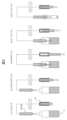
- Fig. 3 is a diagram showing an example of a reagent dispensing operation sequence. Note that Fig. 3 shows a simplified configuration of the reagent dispensing mechanism, unlike Fig. 2.
- the control unit 24 moves the reagent nozzles 12, 14, which have been cleaned internally and externally, to above the reagent bottle 4, which is the reagent aspirating position. At this time, the insides of the reagent nozzles 12, 14 are filled with the system water used for the internal cleaning.
- the control unit 24 operates the syringe 25 in the suction direction to suction the segmented air.
- the segmented air is the air that separates the system water and the reagent, and serves as an air layer that prevents the reagent from coming into contact with the system water during reagent suction, resulting in dilution of the reagent.
- the control unit 24 lowers the reagent nozzles 12, 14 at the reagent suction position, and while the reagent nozzles 12, 14 are immersed in the liquid surface in the reagent bottle 4, the control unit 24 operates the syringe 25 in the suction direction to aspirate the reagent.
- the amount of reagent aspirated includes a first predetermined amount, which is the amount discharged into the reaction vessel 2 in the (5) second discharge step (i.e., the amount used for analysis), as well as a second predetermined amount, which is discharged back into the reagent bottle 4 in the (4) first discharge step, which will be described later.
- the amount of reagent aspirated in the (3) reagent suction step includes not only the first predetermined amount and the second predetermined amount, but also a third predetermined amount, which is a dummy amount aspirated in excess to prevent dilution of the reagent by the system water remaining in the reagent nozzles 12, 14.
- the third predetermined amount varies depending on the total value of the first predetermined amount and the second predetermined amount, and the greater the total value, the greater the third predetermined amount.
- the pressure sensor 32 measures the pressure in the flow path over a predetermined time range during the aspirating operation of the syringe 25 and stores the pressure in a memory unit (not shown).
- the control unit 24 operates the syringe 25 in the discharging direction to discharge a portion of the reagent in the reagent nozzles 12, 14 while the reagent nozzles 12, 14 are immersed in the liquid surface in the reagent bottle 4.
- the second predetermined amount which is the amount of reagent discharged in (4) the first discharging step, includes the syringe operation amount (backlash discharge amount) required to cancel the backlash that occurs in the process of transitioning from (3) the reagent suction step to (4) the first discharging step.
- backlash refers to the minute idling that occurs when the operating direction of the syringe 25 is reversed due to gaps that exist between the mechanisms that make up the syringe 25.
- the control unit 24 raises the reagent nozzles 12, 14, moves them horizontally above the reaction vessel 2, which is the reagent ejection position, and then lowers them again. Thereafter, in (5) the second ejection step, the control unit 24 operates the syringe 25 in the ejection direction to eject a portion of the reagent remaining in the reagent nozzles 12, 14 into the reaction vessel 2.
- the first predetermined amount which is the amount of reagent ejected in (5) the second ejection step, corresponds to the amount of reagent required for the actual analysis. Note that in (5) the second ejection step, because the syringe 25 operates in the same direction as the immediately preceding ejection operation, there is no need to consider backlash, and it is possible to eject the required amount of reagent with high accuracy.
- a third predetermined amount of reagent which is a dummy amount, remains in the reagent nozzles 12, 14.
- the third predetermined amount of reagent is discharged together with the cleaning water into the cleaning tanks 20, 21 by the cleaning water supplied from the aforementioned liquid delivery pump 28.
- a method for determining an abnormality during aspiration will be specifically described with reference to Fig. 4.
- the description will be given taking as an example an empty aspiration, in which the dispensing mechanism does not sufficiently aspire the reagent, as an example of an abnormality to be determined for aspiration.
- the abnormality may also be a state in which the dispensing mechanism is clogged with reagent, or an air bubble has entered the dispensing mechanism, etc.
- FIG. 4 is a flowchart showing a method for determining whether or not the device is dry-suctioned. Each step shown in FIG. 4 is assumed to be executed by the control unit 24, but may also be executed by an abnormality determination control unit separate from the control unit 24.
- control unit 24 reads the data of the measurement value by the pressure sensor 32 stored in a memory unit (not shown) (step S401).
- control unit 24 calculates a predetermined index using the measurement value of the pressure sensor 32 (step S402).
- the index used in this embodiment is calculated based on the integrated value of the measurement value of the pressure sensor 32, but an index calculated by another method may also be used.
- the control unit 24 judges whether the index satisfies a predetermined judgment condition (step S403).
- a predetermined judgment condition is whether the index is greater than a constant k is described below, but other judgment conditions may be used. If the index does not satisfy the judgment condition, i.e., if the index is less than or equal to k, the control unit 24 judges it to be normal (step S404).
- step S403 if the index satisfies the judgment condition in step S403, i.e., if the index>k, the control unit 24 judges that a dry suction abnormality has occurred (step S405). At this time, the control unit 24 stops dispensing of reagent from the reagent bottle 4 (step S406). Furthermore, the control unit 24 displays an alert on the display unit (not shown) to inform the user that a dry suction abnormality has occurred and that dispensing of reagent has been stopped (step S407).
- the abnormality determination process shown in FIG. 4 may be performed at any time after the (3) reagent suction step in FIG. 3. However, it is preferable to perform the abnormality determination before the (5) second discharge step in FIG. 3 to prevent the reagent from being discharged into the reaction vessel 2 in the event of an abnormality.
- Figure 5 is a flow chart showing the method for adjusting the amount of reagent aspirated.
- control unit 24 acquires the amount of reagent used corresponding to the analysis request item as the first predetermined amount (step S501).
- control unit 24 determines whether the first predetermined amount is equal to or greater than the first predetermined amount threshold (step S502). If the first predetermined amount is equal to or greater than the first predetermined amount threshold, the control unit 24 sets the second predetermined amount to the backlash discharge amount (constant value) (step S503).
- the control unit 24 sets the second predetermined amount to be greater than the backlash discharge amount (step S504).
- the vertical axis represents the output value of the pressure sensor 32, but this is not limited to the measured pressure value and may be the current value detected by the pressure sensor 32.
- the backlash discharge volume of the syringe 25 used to obtain the pressure waveforms shown in Figures 6A and 6B is set to 2 ⁇ L.
- the difference in pressure waveforms between normal aspiration and dry aspiration is small, so the difference between the respective indices is also small. Therefore, it is difficult to set a judgment condition that clearly indicates dry aspiration, and it is not easy to accurately judge dry aspiration.
- FIG. 6B is a diagram showing an example of the pressure waveform during normal aspirating and the pressure waveform during dry aspirating when the first predetermined amount is 10 ⁇ L and the second predetermined amount is the backlash discharge amount + adjustment amount 40 ⁇ L, as an embodiment.
- the third predetermined amount in the case of FIG. 6B is 7 ⁇ L
- 10 + 2 + 40 + 7 59 ⁇ L of reagent is aspirated in the reagent aspirating step (3).
- the difference in the pressure waveform between normal aspirating and dry aspirating is large, so the difference between the respective indexes is also large. Therefore, it is easy to set a judgment condition that can be clearly regarded as dry aspirating, and it is possible to accurately judge dry aspirating.
- the first predetermined amount is 50 ⁇ L or more
- the second predetermined amount is only the backlash ejection amount
- the amount of reagent aspirated in the (3) reagent aspirating process will be 59 ⁇ L or more, and dry aspiration can be accurately determined. Therefore, if a value of 50 ⁇ L or more is set as the first predetermined amount threshold, when the first predetermined amount is equal to or greater than the first predetermined amount threshold, the second predetermined amount can be set to the backlash ejection amount (2 ⁇ L) regardless of the first predetermined amount.
- the second predetermined amount is made greater than the backlash ejection amount (2 ⁇ L).
- the sum of the first predetermined amount and the second predetermined amount is made equal to the sum of the first predetermined amount threshold and the backlash ejection amount.
- the first predetermined amount is 20 ⁇ L
- the second predetermined amount is made equal to the backlash ejection amount (2 ⁇ L) + 30 ⁇ L, so that the sum of the first predetermined amount and the second predetermined amount is equal to the sum of the first predetermined amount threshold (e.g., 50 ⁇ L) and the backlash ejection amount (2 ⁇ L).
- the sum of the first predetermined amount and the second predetermined amount may be greater than the sum of the first predetermined amount threshold and the backlash ejection amount.
- the second predetermined amount may be the backlash ejection amount (2 ⁇ L) + 50 ⁇ L
- the sum of the first predetermined amount and the second predetermined amount may be greater than the sum of the first predetermined amount threshold (e.g., 50 ⁇ L) and the backlash ejection amount (2 ⁇ L).
- the first predetermined amount threshold is not limited to 50 ⁇ L, and a different value may be used depending on the type of reagent, the inner diameter of the reagent nozzles 12 and 14, the sensitivity of the pressure sensor 32, etc.
- the reagent contains an organic solvent (e.g., acetonitrile)
- the pressure difference between normal aspiration and dry aspiration tends to be smaller compared to when the reagent does not contain an organic solvent, so the first predetermined amount threshold may be set larger.
- Fig. 7 is a diagram showing an example of a method for setting a pressure threshold value for determining dry suction.
- the sum of the first and second predetermined amounts is the sum of a virtual value and a constant value (backlash discharge amount).
- the distribution A of the indices during dry suction falls within a range defined by a predetermined standard deviation with respect to the average value a of the multiple indices
- the distribution B of the indices during normal suction falls within a range defined by a predetermined standard deviation with respect to the average value b of the multiple indices.
- reaction disk 1... reaction disk, 2... reaction vessel, 3... reagent disk, 4... reagent bottle, 6... sample vessel, 7... sample rack, 8... sample transport mechanism, 9... sample dispensing mechanism, 10... sample nozzle, 11, 13... reagent dispensing mechanism, 12, 14... reagent nozzle, 15... cleaning mechanism, 17, 18... stirring mechanism, 19... cleaning tank, 20, 21... cleaning tank, 22, 23... cleaning tank, 24... control unit, 25... syringe, 26... tube, 27... solenoid valve, 28... liquid delivery pump, 29... water supply pump, 30... plunger, 31... motor, 32... pressure sensor.
Landscapes
- Physics & Mathematics (AREA)
- Health & Medical Sciences (AREA)
- Life Sciences & Earth Sciences (AREA)
- Chemical & Material Sciences (AREA)
- Analytical Chemistry (AREA)
- Biochemistry (AREA)
- General Health & Medical Sciences (AREA)
- General Physics & Mathematics (AREA)
- Immunology (AREA)
- Pathology (AREA)
- Automatic Analysis And Handling Materials Therefor (AREA)
Priority Applications (3)
| Application Number | Priority Date | Filing Date | Title |
|---|---|---|---|
| JP2025522311A JPWO2024241921A1 (https=) | 2023-05-19 | 2024-05-10 | |
| EP24810929.0A EP4715391A1 (en) | 2023-05-19 | 2024-05-10 | Automatic analysis device |
| CN202480013528.4A CN120712481A (zh) | 2023-05-19 | 2024-05-10 | 自动分析装置 |
Applications Claiming Priority (2)
| Application Number | Priority Date | Filing Date | Title |
|---|---|---|---|
| JP2023083063 | 2023-05-19 | ||
| JP2023-083063 | 2023-05-19 |
Publications (1)
| Publication Number | Publication Date |
|---|---|
| WO2024241921A1 true WO2024241921A1 (ja) | 2024-11-28 |
Family
ID=93589800
Family Applications (1)
| Application Number | Title | Priority Date | Filing Date |
|---|---|---|---|
| PCT/JP2024/017482 Ceased WO2024241921A1 (ja) | 2023-05-19 | 2024-05-10 | 自動分析装置 |
Country Status (4)
| Country | Link |
|---|---|
| EP (1) | EP4715391A1 (https=) |
| JP (1) | JPWO2024241921A1 (https=) |
| CN (1) | CN120712481A (https=) |
| WO (1) | WO2024241921A1 (https=) |
Citations (6)
| Publication number | Priority date | Publication date | Assignee | Title |
|---|---|---|---|---|
| JPH0429033A (ja) * | 1990-05-25 | 1992-01-31 | Sanyo Electric Co Ltd | 血漿滴下制御装置 |
| JP2002333449A (ja) * | 2001-05-10 | 2002-11-22 | Hitachi Ltd | サンプル分注装置及びそれを用いた自動分析装置 |
| JP2007315984A (ja) | 2006-05-29 | 2007-12-06 | Hitachi High-Technologies Corp | 自動分析装置 |
| JP3150157U (ja) * | 2009-02-17 | 2009-04-30 | 株式会社島津製作所 | 試料分注装置 |
| JP2014002099A (ja) * | 2012-06-20 | 2014-01-09 | Shimadzu Corp | 原子吸光分光光度計のオートサンプラ |
| JP2017009362A (ja) * | 2015-06-19 | 2017-01-12 | 株式会社日立ハイテクノロジーズ | 自動分析装置 |
-
2024
- 2024-05-10 JP JP2025522311A patent/JPWO2024241921A1/ja active Pending
- 2024-05-10 CN CN202480013528.4A patent/CN120712481A/zh active Pending
- 2024-05-10 EP EP24810929.0A patent/EP4715391A1/en active Pending
- 2024-05-10 WO PCT/JP2024/017482 patent/WO2024241921A1/ja not_active Ceased
Patent Citations (6)
| Publication number | Priority date | Publication date | Assignee | Title |
|---|---|---|---|---|
| JPH0429033A (ja) * | 1990-05-25 | 1992-01-31 | Sanyo Electric Co Ltd | 血漿滴下制御装置 |
| JP2002333449A (ja) * | 2001-05-10 | 2002-11-22 | Hitachi Ltd | サンプル分注装置及びそれを用いた自動分析装置 |
| JP2007315984A (ja) | 2006-05-29 | 2007-12-06 | Hitachi High-Technologies Corp | 自動分析装置 |
| JP3150157U (ja) * | 2009-02-17 | 2009-04-30 | 株式会社島津製作所 | 試料分注装置 |
| JP2014002099A (ja) * | 2012-06-20 | 2014-01-09 | Shimadzu Corp | 原子吸光分光光度計のオートサンプラ |
| JP2017009362A (ja) * | 2015-06-19 | 2017-01-12 | 株式会社日立ハイテクノロジーズ | 自動分析装置 |
Non-Patent Citations (1)
| Title |
|---|
| See also references of EP4715391A1 |
Also Published As
| Publication number | Publication date |
|---|---|
| JPWO2024241921A1 (https=) | 2024-11-28 |
| CN120712481A (zh) | 2025-09-26 |
| EP4715391A1 (en) | 2026-03-25 |
Similar Documents
| Publication | Publication Date | Title |
|---|---|---|
| EP2259073B1 (en) | Method of cleaning nozzle | |
| EP1992952B1 (en) | Liquid dispensing apparatus | |
| US9513305B2 (en) | Multiple cleaning stations for a dispensing probe | |
| CN101135694A (zh) | 自动分析装置 | |
| EP2878955B1 (en) | Automated analyzer | |
| JP6635661B2 (ja) | 自動分析装置及び試料希釈攪拌方法 | |
| JP2004170279A (ja) | 自動分析装置 | |
| JP4416579B2 (ja) | 自動分析装置 | |
| US20230341425A1 (en) | Automatic analyzer and dispensing method of reagent | |
| US20190369130A1 (en) | Automatic Analyzer | |
| US12332103B2 (en) | Dispensing device, automated analysis device, and dispensing method | |
| WO2024241921A1 (ja) | 自動分析装置 | |
| JP5487275B2 (ja) | 自動分析装置 | |
| JP7572539B2 (ja) | 自動分析装置 | |
| WO2022255042A1 (ja) | 自動分析装置 | |
| JP7167037B2 (ja) | 自動分析装置および検体分注機構の異常検出方法 | |
| WO2024157846A1 (ja) | 自動分析装置 | |
| JP7817108B2 (ja) | 自動分析装置および洗浄液量の調整方法 | |
| JP2024008589A (ja) | 自動分析装置 | |
| JP4713629B2 (ja) | 自動分析装置 | |
| JP7002669B2 (ja) | 自動分析装置 | |
| WO2025074877A1 (ja) | 自動分析装置およびその分注方法 | |
| JP7221794B2 (ja) | 試薬カートリッジ及び自動分析システム | |
| WO2024252827A1 (ja) | 自動分析装置およびその異常判定方法 | |
| JP5174930B2 (ja) | 自動分析装置 |
Legal Events
| Date | Code | Title | Description |
|---|---|---|---|
| 121 | Ep: the epo has been informed by wipo that ep was designated in this application |
Ref document number: 24810929 Country of ref document: EP Kind code of ref document: A1 |
|
| DPE1 | Request for preliminary examination filed after expiration of 19th month from priority date (pct application filed from 20040101) | ||
| ENP | Entry into the national phase |
Ref document number: 2025522311 Country of ref document: JP Kind code of ref document: A |
|
| WWE | Wipo information: entry into national phase |
Ref document number: 2025522311 Country of ref document: JP |
|
| WWE | Wipo information: entry into national phase |
Ref document number: 2024810929 Country of ref document: EP |
|
| NENP | Non-entry into the national phase |
Ref country code: DE |
|
| ENP | Entry into the national phase |
Ref document number: 2024810929 Country of ref document: EP Effective date: 20251219 |
|
| ENP | Entry into the national phase |
Ref document number: 2024810929 Country of ref document: EP Effective date: 20251219 |
|
| ENP | Entry into the national phase |
Ref document number: 2024810929 Country of ref document: EP Effective date: 20251219 |
|
| ENP | Entry into the national phase |
Ref document number: 2024810929 Country of ref document: EP Effective date: 20251219 |
|
| ENP | Entry into the national phase |
Ref document number: 2024810929 Country of ref document: EP Effective date: 20251219 |
|
| ENP | Entry into the national phase |
Ref document number: 2024810929 Country of ref document: EP Effective date: 20251219 |
|
| ENP | Entry into the national phase |
Ref document number: 2024810929 Country of ref document: EP Effective date: 20251219 |
|
| ENP | Entry into the national phase |
Ref document number: 2024810929 Country of ref document: EP Effective date: 20251219 |
|
| WWP | Wipo information: published in national office |
Ref document number: 2024810929 Country of ref document: EP |