WO2024241378A1 - 医療デバイス、及び、医療デバイスの製造方法 - Google Patents
医療デバイス、及び、医療デバイスの製造方法 Download PDFInfo
- Publication number
- WO2024241378A1 WO2024241378A1 PCT/JP2023/018776 JP2023018776W WO2024241378A1 WO 2024241378 A1 WO2024241378 A1 WO 2024241378A1 JP 2023018776 W JP2023018776 W JP 2023018776W WO 2024241378 A1 WO2024241378 A1 WO 2024241378A1
- Authority
- WO
- WIPO (PCT)
- Prior art keywords
- tube
- tip
- marker
- medical device
- distal
- Prior art date
- Legal status (The legal status is an assumption and is not a legal conclusion. Google has not performed a legal analysis and makes no representation as to the accuracy of the status listed.)
- Ceased
Links
Images






Classifications
-
- A—HUMAN NECESSITIES
- A61—MEDICAL OR VETERINARY SCIENCE; HYGIENE
- A61B—DIAGNOSIS; SURGERY; IDENTIFICATION
- A61B90/00—Instruments, implements or accessories specially adapted for surgery or diagnosis and not covered by any of the groups A61B1/00 - A61B50/00, e.g. for luxation treatment or for protecting wound edges
- A61B90/39—Markers, e.g. radio-opaque or breast lesions markers
-
- A—HUMAN NECESSITIES
- A61—MEDICAL OR VETERINARY SCIENCE; HYGIENE
- A61B—DIAGNOSIS; SURGERY; IDENTIFICATION
- A61B8/00—Diagnosis using ultrasonic, sonic or infrasonic waves
- A61B8/12—Diagnosis using ultrasonic, sonic or infrasonic waves in body cavities or body tracts, e.g. by using catheters
-
- A—HUMAN NECESSITIES
- A61—MEDICAL OR VETERINARY SCIENCE; HYGIENE
- A61B—DIAGNOSIS; SURGERY; IDENTIFICATION
- A61B8/00—Diagnosis using ultrasonic, sonic or infrasonic waves
- A61B8/44—Constructional features of the ultrasonic, sonic or infrasonic diagnostic device
- A61B8/4444—Constructional features of the ultrasonic, sonic or infrasonic diagnostic device related to the probe
- A61B8/445—Details of catheter construction
-
- A—HUMAN NECESSITIES
- A61—MEDICAL OR VETERINARY SCIENCE; HYGIENE
- A61M—DEVICES FOR INTRODUCING MEDIA INTO, OR ONTO, THE BODY; DEVICES FOR TRANSDUCING BODY MEDIA OR FOR TAKING MEDIA FROM THE BODY; DEVICES FOR PRODUCING OR ENDING SLEEP OR STUPOR
- A61M25/00—Catheters; Hollow probes
-
- A—HUMAN NECESSITIES
- A61—MEDICAL OR VETERINARY SCIENCE; HYGIENE
- A61M—DEVICES FOR INTRODUCING MEDIA INTO, OR ONTO, THE BODY; DEVICES FOR TRANSDUCING BODY MEDIA OR FOR TAKING MEDIA FROM THE BODY; DEVICES FOR PRODUCING OR ENDING SLEEP OR STUPOR
- A61M25/00—Catheters; Hollow probes
- A61M25/0021—Catheters; Hollow probes characterised by the form of the tubing
-
- A—HUMAN NECESSITIES
- A61—MEDICAL OR VETERINARY SCIENCE; HYGIENE
- A61B—DIAGNOSIS; SURGERY; IDENTIFICATION
- A61B90/00—Instruments, implements or accessories specially adapted for surgery or diagnosis and not covered by any of the groups A61B1/00 - A61B50/00, e.g. for luxation treatment or for protecting wound edges
- A61B90/39—Markers, e.g. radio-opaque or breast lesions markers
- A61B2090/3966—Radiopaque markers visible in an X-ray image
Definitions
- the present invention relates to a medical device and a method for manufacturing a medical device.
- Patent Document 1 describes a medical device that includes a transducer unit for transmitting and receiving ultrasound toward biological tissue, an imaging lumen for enabling the transducer unit and drive shaft to move, and a guidewire lumen for allowing a guidewire to be inserted.
- the ultrasound image acquisition mechanism including the drive shaft and transducer unit will also be referred to as a "sensor.”
- a configuration is provided with multiple lumens by combining multiple tubes.
- a treatment device e.g., a plasma guidewire or a penetration guidewire
- a configuration is provided with multiple lumens by combining multiple tubes.
- these issues are not limited to medical devices with built-in sensors (i.e., devices that themselves have the ability to acquire ultrasound images), but are also common to medical devices that are configured to allow a sensor to be inserted and are used in combination with the sensor. Furthermore, these issues are not limited to the vascular system, but are common to medical devices that are inserted into various organs within the human body, such as the lymphatic system, biliary system, urinary system, respiratory tract system, digestive system, secretory glands, and reproductive organs.
- the present invention has been made to solve at least some of the above problems, and aims to improve the bonding strength of multiple tubes in a medical device having multiple tubes.
- the present invention has been made to solve at least some of the problems described above, and can be realized in the following form.
- a medical device includes a distal tip and a first tube having a first lumen, the distal end of the first tube being located distal to the base end of the distal tip and on the inner circumferential side of the distal tip, and a second tube having a second lumen and in contact with the distal tip.
- the tip of the first tube is located further distal than the base end of the tip tip and on the inner periphery side of the tip tip, and the second tube is in contact with the tip tip, so that both the first tube and the second tube can be fixed using the tip tip.
- the joining strength of the first and second tubes can be improved compared to when the first and second tubes are joined without using the tip tip.
- the medical device of the above embodiment may further include a radiopaque marker provided on the second tube, the marker being disposed in at least a portion of a longitudinal section of the medical device from the distal end of the first tube to the proximal end of the distal tip.
- the marker makes it possible to grasp the position of the distal tip.
- the marker may be a first marker, and a second marker having radiopacity may be provided at a position closer to the base end than the first marker and distant from the first marker.
- a second marker having radiopacity may be provided at a position closer to the base end than the first marker and distant from the first marker.
- the medical device of the above embodiment may further include a third tube having a third lumen, the distal end opening of which communicates the distal end of the third lumen with the outside, the distal end opening being located near the second marker.
- the distal tip has a first layer and a second layer covering the first layer, the distal end of the first layer is located proximal to the distal end of the second layer, and both the first layer and the second layer may be radiopaque.
- the cross-sectional shape at the base end of the distal tip may be 360-degree symmetric.
- the distal tip has a cross-sectional shape that is 360-degree symmetric at the base end, making it easier for the surgeon to bend the medical device in the direction intended by the surgeon during a procedure using the medical device.
- the outer periphery of the distal tip may be a substantially elliptical shape in cross section, with the major axis intersecting the first tube and the minor axis not intersecting the first tube. This configuration allows the medical device to be easily bent in the minor axis direction of the outer periphery of the distal tip.
- a method for manufacturing a medical device includes arranging a first tube into which a first core bar is inserted and a second tube into which a second core bar is inserted such that the tip of the first core bar is located proximal to the tip of the first tube, and the tip of the first tube is located proximal to the tip of the second tube, covering the tip of the first tube to the tip of the first core bar with a heat shrink tube, and forming a tip portion on the tip side of the first tube in which the lumen in the first tube is blocked and which extends along the outer circumferential surface of the second tube distal to the blocked end by utilizing the heat shrink of the heat shrink tube.
- a tip portion having a shape suitable for fixation using a tip tip can be formed on the tip side of the first tube.
- the length of the tip portion can be controlled by adjusting the tip position of the first core bar and the tip position of the first tube.
- the heat shrink tube may be a first heat shrink tube
- the tip portion and the second tube may be covered with a resin cylindrical member
- the cylindrical member may be covered with a second heat shrink tube
- the cylindrical member may be fixed to the tip portion of the first tube and the second tube by utilizing the heat shrinkage of the second heat shrink tube.
- the tip portion of the first tube and the second tube are sandwiched and fixed using a second core bar and a cylindrical member, so that the first tube and the second tube can be firmly fixed.
- the cylindrical member may be a first cylindrical member, and the first cylindrical member may be covered with a second cylindrical member made of resin, and the second cylindrical member may be fixed to the first cylindrical member by welding the second cylindrical member, and the distal end side of the second cylindrical member may be tapered to form the distal tip.
- This manufacturing method allows the formation of a distal tip with a two-layer structure.
- the present invention can be realized in various forms, such as medical devices, medical tubes, catheters, and methods for manufacturing these.
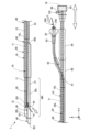
- FIG. 1 is an explanatory diagram illustrating a configuration of a medical device.
- FIG. 1 is an explanatory diagram illustrating a configuration of a medical device.
- FIG. 2 is a cross-sectional view of the catheter.
- FIG. 1 is a diagram illustrating a method of using a catheter.
- FIG. 1 is a diagram illustrating a method of using a catheter.
- FIG. 2 is an enlarged view of the tip side of the catheter.
- FIG. 2 is a cross-sectional view of the components of the catheter.
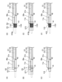
- 1A to 1C are diagrams illustrating a manufacturing method of a catheter.
- 1A to 1C are diagrams illustrating a manufacturing method of a catheter.
- FIG. 11 is an enlarged view of the distal end side of the catheter of the second embodiment.
- FIG. 11 is an enlarged view of the tip side of the catheter of the third embodiment.
- FIG. 13 is an enlarged view of the tip side of the catheter of the fourth embodiment.
- FIG. 13 is
- First Embodiment 1 and 2 are explanatory diagrams illustrating the configuration of a medical device 1.
- the medical device 1 of this embodiment is a catheter.
- the medical device 1 is also referred to as a "catheter 1".
- the catheter 1 is used to treat a lesion in a living lumen, such as a CTO occurring in a blood vessel. As shown in FIG. 1 and FIG.
- the catheter 1 includes a sensor tube 10, an over-the-wire (OTW) tube 20, a rapid exchange (RX) tube 30, a distal tip 40, a first marker 41, a second marker 42, a first outer tube 50, a branch connector 60, a first reinforcing member 61 to a third reinforcing member 63, a cylindrical member 64, a connector 65, a connector 25, a sensor 70, a second outer tube 80, and a heat shrink tube 90.
- the sensor tube 10 is also referred to as a "medical device” or a “medical tube”.
- the OTW tube 20 is also called a "medical device” or a “medical tube.”
- the sensor 70 is not shown in order to explain the configuration of the tube and the lumen within the tube.
- the sensor 70 built into the sensor lumen 10L in the sensor tube 10 is shown by a dashed line and hatched with diagonal lines.
- FIG. 1 and FIG. 2 for the sake of convenience, the relative size ratio of each component is different from the actual one. Also, some of the components are exaggerated. Also, in FIG. 1 and FIG. 2, mutually orthogonal XYZ axes are illustrated.
- the X axis corresponds to the longitudinal direction of the catheter 1
- the Y axis corresponds to the height direction of the catheter 1
- the Z axis corresponds to the width direction of the catheter 1.
- the left side (-X axis direction) of FIG. 1 and FIG. 2 is called the "tip side" of the catheter 1 and each component
- the right side (+X axis direction) of FIG. 1 and FIG. 2 is called the "base end side" of the catheter 1 and each component.
- the one end located on the tip side is called the "tip” and the other end located on the base side is called the “base end”.
- the tip and its vicinity are called the “tip portion”, and the base end and its vicinity are called the “base end portion”.
- the tip side is inserted into the living body, and the base side is operated by an operator such as a doctor.
- Figure 3 is a cross-sectional view of the catheter 1.
- Figure 3(A) shows a cross-section of the catheter 1 taken along line A-A in Figure 1.
- Figure 3(B) shows a cross-section of the catheter 1 taken along line B-B in Figure 1.
- Figure 3(C) shows a cross-section of the catheter 1 taken along line C-C in Figure 1.
- Figure 3(D) shows a cross-section of the catheter 1 taken along line D-D in Figure 1.
- Figure 3(E) shows a cross-section of the catheter 1 taken along line E-E in Figure 1.
- the configuration of the catheter 1 will be explained below using Figures 1 to 3.
- the sensor tube 10 is a cylindrical member (tubular body) with a long outer shape.
- the sensor tube 10 extends linearly along the longitudinal direction (X-axis direction) of the catheter 1, parallel to the OTW tube 20 and the RX tube 30.
- a sensor lumen 10L (dashed line) for accommodating the sensor 70 is formed inside the sensor tube 10.
- the sensor lumen 10L is a lumen for the sensor 70.
- the tip of the sensor tube 10 is located at the same position as or slightly closer to the base end than the tip of the RX tube 30 in the longitudinal direction of the catheter 1.
- a tip opening 101 is formed at the tip of the sensor tube 10, connecting the tip of the sensor lumen 10L to the outside.
- the tip opening 101 is a fluid outlet for keeping the inside of the sensor lumen 10L wet.
- the base end of the sensor tube 10 is located closer to the base end than the base end of the OTW lumen 20L and the base end of the RX tube 30 in the longitudinal direction of the catheter 1.
- a first reinforcing member 61, a branch connector 60, a cylindrical member 64, and a connector 65 are attached to the base end side of the sensor tube 10 from the tip side toward the base end side. Details will be described later.
- a fluid supply unit 66 is attached to the connector 65, and a base end opening 102 is formed in the fluid supply unit 66, connecting the base end of the sensor lumen 10L to the outside.
- the proximal opening 102 is a fluid supply port to the sensor lumen 10L.
- the sensor tube 10 has a distal tube 11 arranged on the distal side, and a base tube 12 arranged on the proximal side of the distal tube 11.
- the distal tube 11 and the base tube 12 are both cylindrical members (tubular bodies) having an elongated outer shape.
- the distal tube 11 and the base tube 12 are connected inside the first outer tube 50 in the longitudinal direction.
- the distal tube 11 and the base tube 12 each constitute a part of the sensor lumen 10L.
- the OTW tube 20 is a cylindrical member (tubular body) having a long outer shape.
- the OTW tube 20 extends linearly along the longitudinal direction of the catheter 1 in parallel with the sensor tube 10 and the RX tube 30 on the distal side of the branch connector 60.
- An OTW lumen 20L (dashed line) for accommodating a treatment device (e.g., a plasma guidewire or a penetration guidewire) is formed inside the OTW tube 20.
- the OTW lumen 20L does not have a proximal opening in the portion that is placed in the biological lumen when the catheter 1 is in use.
- the OTW lumen 20L is an over-the-wire (OTW) type lumen.
- the tip of the OTW tube 20 is located on the proximal side of the tip of the sensor tube 10 and the tip of the RX tube 30 in the longitudinal direction of the catheter 1.
- a tip opening 201 is formed at the tip of the OTW tube 20, which connects the tip of the OTW lumen 20L to the outside.
- the tip opening 201 is a device projection port for projecting a therapeutic device toward biological tissue.
- the tip of the OTW tube 20 is cut at an angle, so that the tip opening 201 faces in a direction intersecting the longitudinal direction of the catheter 1. This makes it easier for the therapeutic device to reach the biological tissue present around the catheter 1 when the catheter 1 is in use.
- the base end of the OTW tube 20 is located on the distal side of the base end of the sensor tube 10 and on the proximal side of the base end of the RX tube 30 in the longitudinal direction of the catheter 1.
- a first reinforcing member 61, a branch connector 60, a second reinforcing member 62, a third reinforcing member 63, and a connector 25 are attached on the base end side of the OTW tube 20, from the tip side to the base end side.
- the connector 25 has a base end opening 202 that connects the base end of the OTW lumen 20L to the outside.
- the base end opening 202 is a device insertion port for inserting a therapeutic device into the OTW lumen 20L.
- the OTW tube 20 has a distal tube 21 disposed on the distal side, and a proximal tube 22 disposed on the proximal side of the distal tube 21.
- the distal tube 21 and the proximal tube 22 are both cylindrical members (tubular bodies) having an elongated outer shape.
- the distal tube 21 and the proximal tube 22 are connected inside the first outer tube 50 in the longitudinal direction. That is, the distal tube 21 and the proximal tube 22 each constitute a part of the OTW lumen 20L.
- the RX tube 30 is a cylindrical member (tubular body) with a long outer shape.
- the RX tube 30 extends linearly along the longitudinal direction of the catheter 1, parallel to the sensor tube 10 and the OTW tube 20.
- An RX lumen 30L (dashed line) for accommodating the work hose wire is formed inside the RX tube 30.
- the tip of the RX tube 30 is located at the same position as or slightly distal to the tip of the sensor tube 10 in the longitudinal direction of the catheter 1.
- a hollow tip tip 40 is joined to the tip of the RX tube 30.
- a tip opening 301 is formed at the tip of the tip tip 40, which connects the tip of the RX lumen 30L to the outside.
- the tip opening 301 is a wire insertion port for inserting the work hose wire into the RX lumen 30L.
- the base end of the RX tube 30 is located distal to the base end of the sensor tube 10 and the base end of the OTW tube 20 in the longitudinal direction of the catheter 1.
- a base end opening 302 is formed at the base end of the RX tube 30, which connects the base end of the RX lumen 30L to the outside.
- the base end opening 302 is a wire withdrawal port for drawing the work hose wire out to the outside.
- the base end opening 302 faces in a direction that intersects with the longitudinal direction of the catheter 1. This makes it easier to pull out the work hose wire from the base end opening 302 when the catheter 1 is in use.
- the distal tip 40 is a radiopaque cylindrical member whose outer diameter expands from the distal end to the proximal end.
- the distal tip 40 is joined to the distal end of the RX tube 30, so that it is positioned at the distal end of the catheter 1 and advances through the biological lumen ahead of other members.
- the lumen of the distal tip 40 is connected to the RX lumen 30L of the RX tube 30, and at the distal end of the distal tip 40, as described above, a distal opening 301 is formed that connects the distal end of the RX lumen 30L to the outside.
- the first marker 41 and the second marker 42 are annular members having radiopaque properties.
- the first marker 41 is arranged so that the base end of the first marker 41 and the base end of the distal tip 40 are at the same position in the longitudinal direction of the catheter 1.
- the first marker 41 is embedded between the outer peripheral surface of the RX tube 30 and the inner peripheral surface of the distal tip 40.
- the second marker 42 is arranged so that the base end of the second marker 42 and the tip of the distal opening 201 are at the same position in the longitudinal direction of the catheter 1.
- the second marker 42 is bonded to the outer peripheral surface of the RX tube 30.
- the first marker 41 and the second marker 42 can be bonded, for example, by bonding resins together by thermal melting or by bonding with an adhesive such as an epoxy adhesive.
- the second marker 42 may be colored so that it can be directly viewed by the surgeon. In this way, by arranging the first marker 41 and the second marker 42 on the RX tube 30, it is possible to prevent the first marker 41 and the second marker 42 from interfering with sensing (acquisition of image information) by the sensor 70.
- the first marker 41 is also simply referred to as the "marker.”
- the sensor tube 10 in the cross section taken along line A-A, the sensor tube 10 (specifically, the distal tube 11) and the RX tube 30 are arranged, and their outer circumferential surfaces are joined together.
- the sensor tube 10 in the cross section taken along line B-B, the sensor tube 10 (specifically, the distal tube 11), the OTW tube 20 (specifically, the distal tube 21), and the RX tube 30 are arranged, and their outer circumferential surfaces are joined together.
- the sensor tube 10 in the cross section taken along line C-C, the sensor tube 10 (specifically, the distal tube 11), the OTW tube 20 (specifically, the distal tube 21), and the RX tube 30 are covered by the first outer tube 50.
- the three tubes 10, 20, and 30 are fixed together by having the outer circumferential surfaces of each of the three tubes 10, 20, and 30 covered by the melt-formed first outer tube 50.
- the sensor tube 10 in the cross section taken along line D-D, the sensor tube 10 (specifically, the distal tube 11), the OTW tube 20 (specifically, the proximal tube 22), and the RX tube 30 are covered by the first outer tube 50, as in FIG. 3(C).
- FIG. 3(E) in the cross section taken along line E-E, the sensor tube 10 (specifically, the proximal tube 12) and the OTW tube 20 (specifically, the proximal tube 22) are covered by the second outer tube 80.
- the two tubes 10, 20 are fixed together by having the outer circumferential surfaces of the two tubes 10, 20 covered by the melt-formed second outer tube 80.
- the sensor tube 10, the OTW tube 20, and the RX tube 30 may be joined in the A-A cross section and the B-B cross section using any bonding agent such as an epoxy adhesive, or may be welded by heat.
- the height LY of the catheter 1 is greater than the width LZ of the catheter 1.
- the height LY of the catheter 1 is less than the width LZ of the catheter 1.
- the relationship of the inner diameters (lumens) of the three tubes 10, 20, and 30 is the inner diameter of the sensor lumen 10L > the inner diameter of the OTW lumen 20L > the inner diameter of the RX lumen 30L.
- these outer and inner diameters are merely examples and may be changed as desired.
- the A-A and B-B cross sections in other words, the outer shape of the catheter 1 on the distal side of the first outer tube 50, is a shape that follows the contours of the two tubes 10, 30 (or the three tubes 10, 20, 30) arranged next to each other, and a constriction (concave) is formed in the adjacent portion of each tube.
- the C-C and D-D cross sections in other words, the outer shape of the catheter 1 in the portion covered by the first outer tube 50, is a triangle with rounded corners (round-cornered triangle).
- the E-E cross section in other words, the outer shape of the catheter 1 in the portion covered by the second outer tube 80, is an ellipse.
- the three tubes 10, 20, and 30 (specifically, the sensor tube 10, the OTW tube 20, and the RX tube 30) are fixed by the three tubes 90, 50, and 80.
- the heat shrink tube 90 is disposed between the first outer tube 50 and the second outer tube 80 in the longitudinal direction of the catheter 1.
- the heat shrink tube 90 covers the sensor tube 10 (specifically, a portion of the distal end of the base end tube 12) and the OTW tube 20 (specifically, a portion of the distal end of the base end tube 22) to bundle the two tubes 10, 20.
- the heat shrink tube 90 does not cover the RX tube 30, and the RX tube 30 is disposed along the outer circumferential surface of the heat shrink tube 90 with the outer circumferential surface of the heat shrink tube 90 in contact with the outer circumferential surface of the RX tube 30.
- the tip of the heat shrink tube 90 is located on the proximal side of the tip of the first outer tube 50 and on the distal side of the base end opening 302. In other words, the tip of the heat shrink tube 90 is covered by the first outer tube 50.
- the base end of the heat shrink tube 90 is located closer to the base end than the tip of the second outer tube 80 and closer to the tip end than the first reinforcing member 61. That is, the base end of the heat shrink tube 90 is covered by the second outer tube 80. In other words, the middle portion of the heat shrink tube 90 in the longitudinal direction of the catheter 1 is not covered by the first outer tube 50 or the second outer tube 80.
- the first outer tube 50 is disposed on the distal side of the heat shrink tube 90 in the longitudinal direction of the catheter 1.
- the first outer tube 50 is disposed on the proximal side of the distal opening 201, in a section where the three tubes 10, 20, 30 extend side by side.
- the distal end of the first outer tube 50 is located near the center between the distal opening 201 and the proximal opening 302.
- the proximal end of the first outer tube 50 is located near the proximal end of the proximal opening 302. In this way, it is preferable that the first outer tube 50 is disposed at a position away from the distal opening 201 on the proximal side.
- the first outer tube 50 covers and fixes the tip of the heat shrink tube 90, the sensor tube 10 exposed from the tip of the heat shrink tube 90 (specifically, a portion of the base end side of the tip tube 11), the OTW tube 20 exposed from the tip of the heat shrink tube 90 (specifically, a portion of the base end side of the tip tube 21 and a portion of the tip end side of the base end tube 22), and the RX tube 30.
- the first outer tube 50 has an outer shape of a rounded triangle and has a thick wall portion melt-molded along the outer circumferential surfaces of the three tubes 10, 20, and 30.
- the second outer tube 80 is disposed on the base end side of the heat shrink tube 90 in the longitudinal direction of the catheter 1.
- the second outer tube 80 is disposed on the base end side of the base end opening 302, in the section where the two tubes 10, 20 extend side by side.
- the tip of the second outer tube 80 is located slightly away from the base end opening 302 toward the base end.
- the base end of the second outer tube 80 is located inside the first reinforcing member 61.
- the second outer tube 80 covers and fixes the base end of the heat shrink tube 90, the sensor tube 10 exposed from the base end of the heat shrink tube 90 (specifically, a portion of the base end side of the base end tube 12), and the OTW tube 20 exposed from the base end of the heat shrink tube 90 (specifically, a portion of the base end tube 22).
- the second outer tube 80 has an elliptical outer shape and has a thick portion that is melt-molded along the outer circumferential surfaces of the two tubes 10 and 20.
- the branch connector 60 is a member having a bifurcated lumen, and is disposed on the base end side of the catheter 1.
- the OTW tube 20 is inserted into one lumen of the branch connector 60.
- the sensor tube 10 is inserted into the other lumen of the branch connector 60.
- the first reinforcing member 61 is a cylindrical member disposed on the distal side of the branch connector 60. The first reinforcing member 61 reinforces the distal side of the branch connector 60 by covering the outer periphery of the second outer tube 80 that bundles the sensor tube 10 and the OTW tube 20 together.
- the second reinforcing member 62 is a cylindrical member disposed on the base end side of one branch of the branch connector 60.
- the second reinforcing member 62 reinforces the base end side of the branch connector 60 by covering the outer periphery of the OTW tube 20 inserted into the branch connector 60.
- the third reinforcing member 63 is a cylindrical member disposed on the distal end side of the connector 25.
- the third reinforcing member 63 reinforces the distal end side of the connector 25 by covering the outer periphery of the OTW tube 20 inserted into the connector 25.
- the connector 25 is a member joined to the base end of the OTW tube 20.
- the connector 25 has a pair of wings for the surgeon to grasp.
- the base end of the connector 25 is formed with a base end opening 202 (device insertion port) that connects the base end of the OTW lumen 20L to the outside.
- the tubular member 64 is a cylindrical member located closer to the base end than the other branch of the branch connector 60.
- the tubular member 64 reinforces the base end of the branch connector 60 by covering the outer periphery of the sensor tube 10 inserted into the branch connector 60.
- the connector 65 is a member joined to the base end of the sensor tube 10.
- a housing for accommodating the connection terminal 75 of the sensor 70 is provided on the base end side of the connector 65.
- a fluid supply section 66 is provided on the outer periphery of the connector 65, with a base end opening 102 formed therein that communicates between the base end of the sensor lumen 10L and the outside.
- the sensor 70 (FIG. 2) is an imaging sensor for acquiring image information. As shown in FIG. 2, the sensor 70 includes a main body 71, a probe 72, and a connection terminal 75.
- the main body 71 is an elongated member extending along the longitudinal direction of the catheter 1.
- a driving cable (coaxial line) that electrically connects the probe 72 and the connection terminal 75 is built into the inside of the main body 71.
- the probe 72 includes an ultrasonic probe (also called an ultrasonic vibrator, piezoelectric body, ultrasonic transmission/reception element, or ultrasonic element) that transmits ultrasonic waves toward biological tissue and receives ultrasonic waves reflected by the biological tissue.
- the probe 72 is also called an imaging core or transducer.
- the connection terminal 75 is a terminal that electrically connects the sensor 70 to an external console terminal.
- the connection terminal 75 is provided at the base end of the main body 71 and is housed in the housing of the connector 65.
- the sensor 70 is electrically connected to an external console terminal via a connection terminal 75, receives power from the console terminal, and outputs a detection signal from the probe 72 to the console terminal. This allows the console terminal to display image information based on the detection signal from the probe 72.
- the sensor 70 is fixed to a connector 65. As shown by the white arrow in FIG. 2, the operator can grasp the connector 65 and slide it in the forward and backward directions (in the direction of the white arrow) to move the position of the probe 72 of the sensor 70 within a range MR from the tip of the sensor lumen 10L to the tip of the first outer tube 50, in other words, within a predetermined range MR including the tip opening 201.
- the range MR is also referred to as the "movable range MR”.
- the part of the catheter 1 that is particularly suitable for sensing (obtaining image information) by the sensor 70 is also referred to as the "acoustic window AW".
- the acoustic window AW is the section of the catheter 1 between the first marker 41 and the second marker 42.
- the distal tube 11 of the sensor tube 10, the distal tube 21 of the OTW tube 20, and the RX tube 30 can be made of flexible materials such as thermoplastic resins such as polyethylene resin, polypropylene resin, and polyurethane, polyvinyl chloride, ethylene-vinyl acetate copolymer, cross-linked ethylene-vinyl acetate copolymer, polyamide elastomer, polyolefin elastomer, polyurethane elastomer, silicone rubber, and latex rubber.
- the distal tube 11 of the sensor tube 10, the distal tube 21 of the OTW tube 20, and the RX tube 30 may be made of the same material or different materials.
- the base end tube 12 of the sensor tube 10 and the base end tube 22 of the OTW tube 20 can be made of a resin having high rigidity, such as nylon resin, polyester resin, PEEK resin, etc.
- the melting points of the base end tube 12 of the sensor tube 10 and the base end tube 22 of the OTW tube 20 are higher than the melting points of the above-mentioned tubes 11, 21, and 30.
- the base end tube 12 of the sensor tube 10 and the base end tube 22 of the OTW tube 20 may be made of the same material or different materials.
- a portion of the base end side of the flexible RX tube 30 is overlapped with the high rigidity base end tube 12 and base end tube 22 (FIG. 1), thereby realizing a gradual change in the rigidity of the catheter 1 (reducing the rigidity gap of the catheter 1).
- any one or more of the distal tube 11 and proximal tube 12 of the sensor tube 10, the distal tube 21 and proximal tube 22 of the OTW tube 20, and the RX tube 30 may have a multi-layer structure in which tubes made of different materials are overlapped.
- the tip 40, the first marker 41, and the second marker 42 can be made of a radiopaque resin material or a metal material.
- a radiopaque resin material when using a radiopaque resin material, they can be formed by mixing a radiopaque material such as bismuth trioxide, tungsten, or barium sulfate with polyamide resin, polyolefin resin, polyester resin, polyurethane resin, silicone resin, or fluororesin.
- a radiopaque metal material they can be formed of gold, platinum, tungsten, or an alloy containing these elements (e.g., platinum-nickel alloy).
- the tip 40, the first marker 41, and the second marker 42 may be formed of the same material or different materials.
- the branch connector 60, the first reinforcing member 61 to the third reinforcing member 63, the tubular member 64, the connector 65, and the connector 25 can be made of a known resin material.
- the branch connector 60, the first reinforcing member 61 to the third reinforcing member 63, the tubular member 64, the connector 65, and the connector 25 may be made of the same material or different materials.
- the heat shrink tube 90 is made of a nylon-based elastomer resin (e.g., polyamide elastomer) that has thermoplastic properties.
- the heat shrink tube 90 has the property of shrinking without melting when heated. Furthermore, the heat shrink tube 90 has improved adhesiveness (the property of easily adhering to other substances) when heated compared to when not heated.
- the heat shrink tube 90 may also be made of polyolefin, FEP (Fluorinated Ethylene Propylene), or silicone.
- the first outer tube 50 and the second outer tube 80 are formed from a nylon-based elastomer resin having thermoplastic properties. Unlike the heat shrink tube 90, the first outer tube 50 and the second outer tube 80 have the property of melting when heated. In this embodiment, the first outer tube 50 uses a resin with a lower Shore hardness than the second outer tube 80. However, the first outer tube 50 and the second outer tube 80 may be formed from the same material or different materials.
- FIGS. 4 and 5 are diagrams explaining how to use the catheter 1. Steps a1 to a6 shown below illustrate an example of attempting to recanalize a CTO (lesion) that has occurred in a blood vessel using a antegrade approach. However, the catheter 1 may also be used in a retrograde approach, or for procedures other than recanalization of a CTO.
- step a3 The surgeon inserts the work horse wire 200 into the blood vessel and delivers the tip of the work horse wire 200 close to the CTO.
- step a3 The surgeon inserts the base end of the work horse wire 200 from the tip opening 301 of the catheter 1, passes it through the RX lumen 30L, and pulls it out from the base opening 302 of the catheter 1 (FIG. 4).
- step a3 The surgeon pushes the catheter 1 along the work horse wire 200 into the blood vessel and delivers the tip of the catheter 1 close to the CTO.
- the catheter 1 may be delivered close to the CTO by passing it through a guiding catheter that has been inserted into the blood vessel in advance along the work horse wire 200.
- the operator grasps the connector 65 and slides it in the forward and backward directions (in the direction of the white arrow in FIG. 5 ) to adjust the position of the probe 72 of the sensor 70 within the movable range MR, while checking the image displayed on the console terminal to align the position and orientation of the CTO and the distal opening 201.
- the position means the position in the extension direction of the blood vessel
- the orientation means the orientation in the circumferential direction of the inner wall of the blood vessel.
- the operator inserts the distal end of the treatment device 300 from the proximal opening 202 of the catheter 1, passes through the OTW lumen 20L, and protrudes from the distal opening 201 of the catheter 1 ( FIG. 5 ).
- the operator uses the treatment device 300 to treat the CTO while checking the image displayed on the console terminal, while adjusting the position of the probe 72 of the sensor 70 within the movable range MR as necessary.
- any device such as a plasma guidewire or a penetration guidewire can be used as the treatment device 300.
- the sensor tube 10, the OTW tube 20, and the RX tube 30 are collectively referred to as the "shaft.”
- the sensor tube 10 (the distal tube 11 and the proximal tube 12) corresponds to the “first tube.”
- the RX tube 30 corresponds to the “second tube.”
- the OTW tube 20 (the distal tube 21 and the proximal tube 22) corresponds to the "third tube.”
- the sensor lumen 10L corresponds to the "first lumen”
- the RX lumen 30L corresponds to the "second lumen”
- the OTW lumen 20L corresponds to the "third lumen.”
- the distal opening 201 corresponds to the "distal opening.”
- “same” and “equal” do not mean strictly the same, but mean that differences due to manufacturing errors and the like are allowed.
- “constant” is synonymous with “approximately constant,” and means that it is approximately constant while allowing for deviations due to manufacturing errors and the like.
- Figure 6 is an enlarged view of the tip side of the catheter 1.
- Figure 7 is a cross-sectional view of the components of the catheter 1.
- Figure 7 (A) shows a cross-section of the catheter 1 taken along line F-F in Figure 6, in other words, a cross-section of the catheter 1 at the base end of the tip tip 40.
- Figure 7 (B) shows a cross-section of the second marker 42. The details of the tip tip 40, first marker 41, and second marker 42 will be described using Figures 6 and 7.
- the distal tip 40 has a two-layer structure consisting of a first layer 410 and a second layer 420.
- the first layer 410 (inner layer) covers the distal end of the RX tube 30 (second tube) and the distal end 110 of the sensor tube 10 (first tube), and fixes them together.
- the second layer 420 (outer layer) covers the first layer 410.
- the distal end 4101 of the first layer 410 is located closer to the base end than the distal end 4201 of the second layer 420.
- the base end 4102 of the first layer 410 is located at the same position as the base end 4202 of the second layer 420.
- the distal end 4201 of the second layer 420 corresponds to the "tip of the distal tip", and the base end 4202 of the second layer 420 corresponds to the "base end of the distal tip”.
- the length L420 of the second layer 420 is longer than the length L410 of the first layer 410 (length L420 ⁇ L410).
- Both the first layer 410 and the second layer 420 are radiopaque.
- the first layer 410 and the second layer 420 can be formed from the radiopaque resin material or radiopaque metal material mentioned above as the material of the distal tip 40.
- the RX tube 30 is located at the innermost position.
- the first marker 41 covers the RX tube 30 with the inner surface of the first marker 41 in contact with the outer surface of the RX tube 30.
- a tip portion 110 is provided on a portion of the outer surface of the first marker 41 (a portion of the outer surface in the +Y direction in the illustrated example) that extends along the outer surface of the RX tube 30 beyond the first marker 41.
- the tip portion 110 is a thick-walled portion having a crescent-shaped cross section formed by melting a portion of the tip side of the sensor tube 10, which would normally have a cylindrical cross section. As shown in FIG.
- the first layer 410 covers the tip portion 110 and the first marker 41 with the inner surface of the first layer 410 in contact with the outer surface of the tip portion 110 and the outer surface of the first marker 41.
- the second layer 420 covers the first layer 410 with the inner surface of the second layer 420 in contact with the outer surface of the first layer 410.
- the RX tube 30 (second tube) is in contact with the tip tip 40 directly at the tip side of the first marker 41, beyond the first marker 41, at the portion where the first marker 41 is provided.
- the tip 1101 of the sensor tube 10 (first tube) is located distally of the base end 4202 of the tip tip and on the inner periphery side of the tip tip 40.
- a protruding portion 111 is formed in the sensor tube 10 on the base side of the tip portion 110, where the wall of the tube is protruding.
- the sensor lumen 10L is reduced in diameter, and a tip opening 101 is formed at the end of the protruding portion 111 (the end farther from the RX tube 30 in the illustrated example) to allow fluid to flow inside and outside the RX lumen 30L.
- the diameter of the tip opening 101 is smaller than the diameter of the sensor 70, so it is not possible to insert the sensor 70 through the tip opening 101.
- the cross-sectional shape of the catheter 1 at the base end of the distal tip 40 is 360-degree symmetric.
- the cross-sectional shape of the catheter 1 is 360-degree symmetric means that the outer circumferential outline of the distal tip 40 (specifically the second layer 420) in that cross section is 360-degree symmetric, and/or the configuration of each component of the catheter 1 in that cross section is 360-degree symmetric.
- 360-degree symmetric means that a symmetrical shape does not appear without one full rotation. For this reason, a configuration in which each component of the catheter 1 all has a circular cross section and these are stacked concentrically is not 360-degree symmetric (it is excluded from the concept of 360-degree symmetry).
- the catheter 1 of this embodiment has a cross-sectional shape that is symmetrical at 360 degrees at the base end of the distal tip 40 because the distal end 110 of the sensor tube 10 is included in a laminated structure, which causes the contour shape and thickness of the outer periphery of the first layer 410 and the contour shape and thickness of the outer periphery of the second layer 420 to become non-uniform.
- the contour of the outer periphery of the tip chip 40 (specifically, the second layer 420) is a substantially elliptical shape.
- FIG. 7(A) illustrates the center O of this ellipse, the major axis AL of the ellipse passing through the center O, and the minor axis AS of the ellipse passing through the center O.
- the major axis AL of the ellipse intersects with the sensor tube 10 (first tube), while the minor axis AS of the ellipse does not intersect with the sensor tube 10.
- the first marker 41 is a radiopaque annular member, and is disposed between the RX tube 30 and the first marker 41 (in other words, on the outer periphery of the RX tube 30 and the inner periphery of the first marker 41) as shown in FIG. 7(A).
- the first marker 41 is disposed in at least a portion of the section from the tip 1101 of the sensor tube 10 (first tube) to the base end 4202 of the tip tip.
- the first marker 41 is disposed such that the tip of the first marker 41 is located near the center of the tip portion 110, and the base end of the first marker 41 is located at the base end 4202 of the tip tip.
- the radiopaque member is disposed in three layers (the first marker 41, the first layer 410, and the second layer 420).
- the second marker 42 is a radiopaque annular member, and is arranged on the outer periphery of the RX tube 30 as shown in FIG. 6.
- the second marker 42 is arranged closer to the base end than the first marker 41 and at a position away from the first marker 41.
- the second marker 42 is arranged such that the base end of the second marker 42 is located at the tip of the distal opening 201 (distal opening) of the OTW lumen 20L (third lumen). This allows the surgeon to recognize the tip position of the distal opening 201 from which the therapeutic device is to be protruded, by referring to the position of the second marker 42 on the X-ray image.
- the length L41 of the first marker 41 in the longitudinal direction of the catheter 1 is longer than the length L42 of the second marker 42 (length L41>L42).
- the first marker 41 and the second marker 42 may have a shape other than a circular ring.
- the first marker 41 and the second marker 42 may have a shape obtained by cutting a ring at an arbitrary angle, or may be linear.
- the first marker 41 and the second marker 42 may have a coil shape in which a wire is wound in a spiral shape.
- the first marker 41 and the second marker 42 may be disposed on a tube other than the RX tube 30 (for example, the sensor tube 10 or the OTW tube 20).
- the first marker 41 and the second marker 42 may be disposed on the same tube as described above, or may be disposed on different tubes.
- FIGs. 8 and 9 are diagrams for explaining the manufacturing method of the catheter 1.
- the first and second cylindrical members are marked with different types of diagonal hatching, and the heat shrink tube is marked with dot hatching.
- the members whose shapes change due to heating or the like in the manufacturing process are marked with "a" at the end of their reference numbers before the change.
- the first to third heat shrink tubes ST1 to ST3 that appear in the following description are tubular bodies made of thermoplastic nylon-based elastomer resin, polyolefin, FEP, silicone, etc., and have the property of not melting when heated but shrinking.
- the first and second cylindrical members 410a and 410b are tubular bodies made of polyurethane resin containing tungsten, and unlike the first to third heat shrink tubes ST1 to ST3, have the property of melting when heated.
- the first and second cylindrical members 410a and 410b may be made of the various materials mentioned above as the material of the distal tip 40.
- the first cylindrical member is also simply called the "cylindrical member.”
- FIG. 8(A) shows the arrangement process.
- the worker prepares the tip tube 11a (first tube) into which the first core C1 is inserted, the RX tube 30a (second tube) into which the second core C2 is inserted, and the tip tube 21a (third tube) into which the third core C3 is inserted.
- the worker arranges each component so that the tip P1 of the first core C1 is located closer to the base end than the tip P2 of the tip tube 11a, and the tip P2 of the tip tube 11a is located closer to the base end than the tip P3 of the RX tube 30a.
- the length from the tip P3 to the tip P1 is longer than the length from the tip P2 to the tip P1.
- the first marker 41 and the second marker 42 are arranged in advance on the RX tube 30a.
- the worker positions the tip of the tip tube 21a so that it is located closer to the base end than the tip P1 of the first core C1.
- the tip tube 21a (third tube) is not used and may be omitted.
- FIG. 8(B) shows the state before heating in the tip forming process.
- the worker covers at least the range from tip P2 of the tip side tube 11a (first tube) to tip P1 of the first core metal C1 with the first heat shrink tube ST1.
- the first heat shrink tube ST1 covers the range from tip P3 of the RX tube 30a (second tube) to the tip P1 of the first core metal C1.
- the worker then heats at least the range from tip P2 to tip P1 at a first temperature.
- the first temperature is the temperature at which the first heat shrink tube ST1 thermally shrinks and the tip side tube 11a melts.
- the first heat shrink tube is also simply called the "heat shrink tube".
- Figure 8 (C) shows the state after heating in the tip forming process. After heating, the worker removes the first heat shrink tube ST1. Then, as shown in Figure 8 (C), the part of the tip tube 11a where the first core C1 is not inserted (i.e., the part from tip P2 to tip P1) melts and is crushed with the thermal shrinkage of the first heat shrink tube ST1, forming a tip 110 extending along the outer circumferential surface of the RX tube 30a. As shown in the figure, the lumen in the tip tube 11a (first tube) is blocked at the tip side of the tip tube 11a (first tube), and the tip 110 is formed on the tip side of the blocked end. Note that a tip opening 101 ( Figure 6) is formed in the protruding part on the base end side of the tip 110 after the first core C1 is removed, but the formation of the tip opening 101 may be omitted.
- Figure 8 (D) shows the placement of the first cylindrical member 410a in the first layer formation process.
- the worker covers the tip 110 of the tip side tube 11a (first tube) and the RX tube 30a (second tube) with the first cylindrical member 410a.
- the first cylindrical member 410a covers the entire portion from the tip P3 of the RX tube 30a to the base end P4 of the tip part 110 of the tip side tube 11a.
- FIG. 8(E) shows the placement of the second heat shrink tube ST2 during the first layer formation process.
- the worker covers the first cylindrical member 410a with the second heat shrink tube ST2.
- the second heat shrink tube ST2 covers the entire first cylindrical member 410a, including the tip end of the first cylindrical member 410a to the base end of the first cylindrical member 410a.
- the worker then heats at least the area where the first cylindrical member 410a is located at the second temperature.
- the second temperature is set to a temperature at which the second heat shrink tube ST2 thermally shrinks and the first cylindrical member 410a melts.
- FIG. 8(F) shows the state after heating in the first layer formation process.
- the worker removes the second heat shrink tube ST2.
- the first cylindrical member 410a melts and is crushed as the second heat shrink tube ST2 heat shrinks, forming the first layer 410 that extends along the tip portion 110 and the tip portion of the RX tube 30a.
- the first layer 410 has an outer edge on the side where the tip portion 110 exists that is inclined compared to the outer edge on the opposite side (in other words, a cross section symmetrical at 360 degrees as described in FIG. 7(A)), and fixes the tip portion 110 of the tip side tube 11a (first tube) and the RX tube 30a (second tube).
- FIG. 9(A) shows the placement of the second cylindrical member 420a during the second layer formation process.
- the worker covers the first layer 410 formed by the first cylindrical member 410a with the second cylindrical member 420a.
- the second cylindrical member 420a covers the entire first layer 410 (first cylindrical member 410a) with its tip located closer to the tip of the first layer 410 (first cylindrical member 410a) and its base located at the same position as the base end of the first layer 410 (first cylindrical member 410a).
- FIG. 9(B) shows the placement of the third heat shrink tube ST3 during the second layer formation process.
- the worker covers the second cylindrical member 420a with the third heat shrink tube ST3.
- the third heat shrink tube ST3 covers the entire second cylindrical member 420a, including the tip end of the second cylindrical member 420a to the base end of the second cylindrical member 420a.
- the worker then heats at least the area where the second cylindrical member 420a is located at a third temperature.
- the third temperature is set to a temperature at which the third heat shrink tube ST3 thermally shrinks and the second cylindrical member 420a melts.
- FIG. 9(C) shows the tip tip formation process.
- the worker removes the third heat shrink tube ST3.
- the second cylindrical member 420a melts and is welded to the first layer 410 (first cylindrical member 410a) as the third heat shrink tube ST3 heat shrinks, forming a second layer 420 that extends along the first layer 410 (first cylindrical member 410a).
- the second layer 420 has an outer edge on the side where the tip portion 110 is present that is inclined compared to the outer edge on the opposite side (in other words, a 360-degree symmetrical cross section as described in FIG. 7(A)), thereby fixing the first layer 410 (first cylindrical member 410a).
- the worker then cuts the tip side of the second layer 420 formed by the second cylindrical member 420a to the specified dimensions required for the tip tip 40, and then performs tapering.
- the tapering process can be performed by heating the tip of the second layer 420 (second cylindrical member 420a) to give the tip a rounded, tapered shape. This allows the formation of a two-layered tip tip 40 consisting of the first layer 410 and the second layer 420, as described in FIG. 6.
- the tip 1101 of the tip side tube 11 is located further distal than the base end 4202 of the tip tip and on the inner periphery side of the tip tip 40, and the RX tube 30 (second tube) is in contact with the tip tip 40, so that both the tip side tube 11 (first tube) and the RX tube 30 (second tube) can be fixed using the tip tip 40.
- the joining strength of the first and second tubes can be improved compared to when the first and second tubes are joined without using the tip tip 40.
- the first marker 41 is arranged in at least a portion of the longitudinal direction of the catheter 1 (medical device) from the tip 1101 of the distal tube 11 (first tube) to the base end 4202 of the distal tip. Therefore, even if the distal tip 40 is not made of a radiopaque material, the position of the distal tip 40 can be grasped by the first marker 41. Furthermore, when the distal tip 40 is made of a radiopaque material as in the above embodiment, the member made of the radiopaque material has a multi-layer structure, which makes it possible to make the image darker under X-ray imaging.
- the catheter 1 of the first embodiment is provided with a radiopaque second marker 42 located closer to the base end than the first marker 41 and away from the first marker 41. Therefore, by having two markers (first marker 41, second marker 42) located away from each other in the longitudinal direction of the catheter 1 (medical device), the visibility of the catheter 1 under X-ray images can be improved. Furthermore, according to the catheter 1 of the first embodiment, the second marker 42 is located near the distal opening 201 of the OTW lumen 20L (third lumen), so that the position of the distal opening 201 of the third lumen can be grasped by the second marker 42.
- the distal tip 40 has a first layer 410 and a second layer 420 covering the first layer 410, as shown in FIG. 6, and therefore the visibility of the distal tip 40 under X-ray images can be improved in the area where the first layer 410 and the second layer 420 overlap.
- the visibility of the distal tip under X-ray images can be further improved in the area where the first layer 410, the second layer 420, and the first marker 41 overlap.
- the distal tip 40 has a cross-sectional shape that is symmetrical at 360 degrees at the base end as shown in FIG. 7, so that the catheter 1 (medical device) can be easily bent in the direction intended by the surgeon in a procedure using the catheter 1.
- the catheter 1 can be easily bent in a specific direction as indicated by the arrow DZ in FIG. 7.
- the outer periphery of the distal tip 40 has a substantially elliptical shape in which the major axis AL intersects with the distal tube 11 (first tube) and the minor axis AS does not intersect with the distal tube 11 (first tube) as shown in FIG. 7. Therefore, the catheter 1 (medical device) can be easily bent in the minor axis direction DZ of the outer periphery of the distal tip 40.
- the length L41 of the first marker 41 is longer than the length L42 of the second marker 42, so that the image of the first marker 41 can be made longer than the image of the second marker 42 on the X-ray image. As a result, the surgeon can easily distinguish between the first marker 41 and the second marker 42.
- the arrangement process shown in FIG. 8(A) can form a tip portion 110 having a shape suitable for fixation using a tip tip 40 (specifically, the first cylindrical member 410a and the second cylindrical member 420a) on the tip side of the tip side tube 11a (first tube).
- the length of the tip portion 110 can be controlled by adjusting the tip position P1 of the first core C1 and the tip position P2 of the tip side tube 11a (first tube).
- the tip portion 110 of the tip tube 11a (first tube) and the RX tube 30a (second tube) are sandwiched and fixed using the second core bar C2 and the first cylindrical member 410a, so that the tip tube 11a and the RX tube 30a can be firmly fixed.
- the second layer forming process shown in Figures 9(A) and (B) can form a two-layered tip tip 40.
- Second Embodiment Fig. 10 is an enlarged view of the tip side of the catheter 1A of the second embodiment.
- the catheter 1A of the second embodiment has a first marker 41A instead of the first marker 41 in the configuration described in the first embodiment.
- a transverse cross-sectional view of the first marker 41A and a transverse cross-sectional view of the second marker 42 are shown in balloons.
- the configuration of the first marker 41A and the second marker 42 can be modified in various ways.
- the first marker 41A has the same length L41A and a thicker thickness T41A than the second marker 42.
- the first marker 41A may have a longer length L41A and a thicker thickness T41A than the second marker 42 (L41A > L42, T41A > T42).
- the visibility of the first marker 41A in an X-ray image may be made higher than that of the second marker 42 by changing the type and mixing ratio of the radiopaque material mixed into the resin material.
- the catheter 1A of the second embodiment as described above can achieve the same effects as the first embodiment described above. Furthermore, according to the catheter 1A (medical device) of the second embodiment, the thickness T41A of the first marker 41A is thicker than the thickness T42 of the second marker 42, so that the image of the first marker 41A can be made darker than the image of the second marker 42 on the X-ray image. As a result, the surgeon can easily distinguish between the first marker 41A and the second marker 42.
- Third Embodiment 11 is an enlarged view of the distal end of a catheter 1B according to a third embodiment.
- the catheter 1B according to the third embodiment includes a first marker 41B instead of the first marker 41 and a second marker 42B instead of the second marker 42 in the configuration described in the first embodiment.
- the first marker 41B is positioned so as not to overlap with the distal tip 40.
- the first marker 41B is positioned so that the distal end of the first marker 41B is adjacent to the proximal end 4202 of the distal tip 40.
- the distal end surface of the first marker 41B is in contact with the proximal end surface of the distal tip 40.
- the second marker 42B is positioned so that the center of the second marker 42B is located in the center of the distal opening 201 (distal opening) of the OTW lumen 20L (third lumen) in the longitudinal direction of the catheter 1B.
- first marker 41B and the second marker 42B can be modified in various ways.
- the first marker 41B may be in contact with the distal tip 40 but may not overlap with the distal tip 40, and the second marker 42B may be positioned at any position near the distal opening 201.
- the catheter 1B of the third embodiment as described above can also achieve the same effects as the first embodiment described above.
- Fourth Embodiment 12 is an enlarged view of the distal end side of the catheter 1C of the fourth embodiment.
- the catheter 1C of the fourth embodiment is provided with a first marker 41C instead of the first marker 41 and a second marker 42C instead of the second marker 42 in the configuration described in the first embodiment.
- the first marker 41C does not overlap with the distal tip 40 and is disposed at a position away from the distal tip 40.
- the second marker 42C is disposed near the distal opening 201 of the OTW lumen 20L (third lumen) and at a position closer to the base end than the distal opening 201.
- the first marker 41C may not contact or overlap the distal tip 40, and the second marker 42C may be disposed at any position near the distal opening 201.
- the catheter 1C of the fourth embodiment as described above can also achieve the same effects as the first embodiment described above.
- Fig. 13 is a cross-sectional view of a catheter 1D of the fifth embodiment.
- Fig. 13 shows a cross-section of the catheter 1D taken along line F-F in Fig. 6, in other words, a cross-section of the catheter 1D at the base end of the distal tip 40D.
- the catheter 1D of the fifth embodiment has a distal tip 40D instead of the distal tip 40 in the configuration described in the first embodiment.
- the distal tip 40D is constructed from a single layer.
- the contour of the outer periphery of the distal tip 40D in the cross section of FIG. 13 is not symmetrical over 360 degrees.
- the configuration of each component of the catheter 1D in the cross section of FIG. 13 is symmetrical over 360 degrees. This is due to the presence of the distal end 110.
- the configuration of the tip tip 40D can be modified in various ways, and it may be formed from a single layer.
- the second layer formation process described in FIG. 9 may be omitted.
- the tip tip 40D may also have a layer configuration of three or more layers.
- a third layer may be layered on the second layer 420 using a third cylindrical member.
- the tip tip 40D may also have a cross-sectional shape other than an elliptical shape. Although a perfect circle is exemplified in FIG. 13, this is not limiting.
- the catheter 1D of the fifth embodiment as described above can also achieve the same effects as the first embodiment described above.
- At least one of the sensor tube 10 and the OTW tube 20 may not have a distal tube 11, 21 and a proximal tube 12, 22, and may be composed of a single tube body (tubular body) from the distal end to the proximal end.
- at least one of the tubes 10, 20, 30 may be composed of three or more tube bodies (tubular bodies) arranged along the longitudinal direction of the catheter 1.
- the outer surfaces of the first outer tube 50, the heat shrink tube 90, and the second outer tube 80, or the outer surface of the catheter 1 including these, may be coated with a hydrophilic resin or a hydrophobic resin.
- the sensor 70 is built into the sensor lumen 10L of the sensor tube 10 and is configured so as not to be removable from the catheter 1. However, the sensor 70 may also be configured so as to be removable from the catheter 1. In other words, the catheter 1 does not have to include the sensor 70 as a component.
- the shapes of the first marker 41 and the second marker 42 can be changed arbitrarily.
- the first marker 41 and the second marker 42 may have a shape other than a ring shape (for example, a shape obtained by cutting a ring at an arbitrary angle, a linear shape, or a coil shape obtained by winding a wire in a spiral shape).
- the first marker 41 and the second marker 42 may be disposed on a tube other than the RX tube 30 (the sensor tube 10 or the OTW tube 20).
- the first marker 41 and the second marker 42 may be disposed on the same tube as described above, or may be disposed on different tubes.
- the tubes 50, 80, and 90 are each composed of one layer, but at least one of the tubes 50, 80, and 90 may be composed of two or more layers.
- the cross-sectional shape of the catheter 1 in the part covered by the first outer tube 50 is a round-cornered triangle shape, but it may be any shape such as a circle or an ellipse.
- the cross-sectional shape of the catheter 1 in the part covered by the second outer tube 80 is an ellipse shape, but it may be any shape such as a circle or a round-cornered triangle.
- at least one of the first outer tube 50 and the second outer tube 80 may have an outer shape that follows the contour of the outer circumferential surface of the tube 10, 20 (or tube 10, 20, 30).
- the shapes of the branch connector 60, the first reinforcing member 61 to the third reinforcing member 63, the cylindrical member 64, the connector 65, and the connector 25 described above are merely examples and may be changed as desired.
- at least a portion of the branch connector 60, the first reinforcing member 61, the second reinforcing member 62, and the cylindrical member 64 may be configured as a single member or may be omitted.
- the third reinforcing member 63 and the connector 25 may be configured as a single member.
- the cylindrical member 64 may be provided with a mechanism (for example, a scale or stopper provided at a predetermined length in the longitudinal direction, or a scale or stopper provided at a predetermined angle in the circumferential direction) that assists in adjusting at least one of the front-to-rear position of the sensor 70 and the orientation of the sensor 70 in the circumferential direction.
- a mechanism for example, a scale or stopper provided at a predetermined length in the longitudinal direction, or a scale or stopper provided at a predetermined angle in the circumferential direction
Landscapes
- Health & Medical Sciences (AREA)
- Life Sciences & Earth Sciences (AREA)
- Surgery (AREA)
- Veterinary Medicine (AREA)
- Public Health (AREA)
- General Health & Medical Sciences (AREA)
- Animal Behavior & Ethology (AREA)
- Engineering & Computer Science (AREA)
- Biomedical Technology (AREA)
- Heart & Thoracic Surgery (AREA)
- Pathology (AREA)
- Molecular Biology (AREA)
- Medical Informatics (AREA)
- Nuclear Medicine, Radiotherapy & Molecular Imaging (AREA)
- Biophysics (AREA)
- Radiology & Medical Imaging (AREA)
- Physics & Mathematics (AREA)
- Oral & Maxillofacial Surgery (AREA)
- Pulmonology (AREA)
- Anesthesiology (AREA)
- Hematology (AREA)
- Media Introduction/Drainage Providing Device (AREA)
Priority Applications (3)
| Application Number | Priority Date | Filing Date | Title |
|---|---|---|---|
| PCT/JP2023/018776 WO2024241378A1 (ja) | 2023-05-19 | 2023-05-19 | 医療デバイス、及び、医療デバイスの製造方法 |
| JP2025521599A JPWO2024241378A1 (https=) | 2023-05-19 | 2023-05-19 | |
| US19/382,305 US20260069244A1 (en) | 2023-05-19 | 2025-11-07 | Medical device and method for manufacturing medical device |
Applications Claiming Priority (1)
| Application Number | Priority Date | Filing Date | Title |
|---|---|---|---|
| PCT/JP2023/018776 WO2024241378A1 (ja) | 2023-05-19 | 2023-05-19 | 医療デバイス、及び、医療デバイスの製造方法 |
Related Child Applications (1)
| Application Number | Title | Priority Date | Filing Date |
|---|---|---|---|
| US19/382,305 Continuation US20260069244A1 (en) | 2023-05-19 | 2025-11-07 | Medical device and method for manufacturing medical device |
Publications (1)
| Publication Number | Publication Date |
|---|---|
| WO2024241378A1 true WO2024241378A1 (ja) | 2024-11-28 |
Family
ID=93589005
Family Applications (1)
| Application Number | Title | Priority Date | Filing Date |
|---|---|---|---|
| PCT/JP2023/018776 Ceased WO2024241378A1 (ja) | 2023-05-19 | 2023-05-19 | 医療デバイス、及び、医療デバイスの製造方法 |
Country Status (3)
| Country | Link |
|---|---|
| US (1) | US20260069244A1 (https=) |
| JP (1) | JPWO2024241378A1 (https=) |
| WO (1) | WO2024241378A1 (https=) |
Citations (6)
| Publication number | Priority date | Publication date | Assignee | Title |
|---|---|---|---|---|
| JP2016501638A (ja) * | 2012-12-21 | 2016-01-21 | クリストファー ルブラン, | 遠位カテーテル先端およびその形成 |
| WO2019181837A1 (ja) * | 2018-03-19 | 2019-09-26 | 日本ゼオン株式会社 | 結石除去用バルーンカテーテル |
| WO2020003492A1 (ja) * | 2018-06-29 | 2020-01-02 | 朝日インテック株式会社 | カテーテル |
| WO2022168386A1 (ja) * | 2021-02-02 | 2022-08-11 | 朝日インテック株式会社 | カテーテル |
| WO2022239763A1 (ja) * | 2021-05-12 | 2022-11-17 | 朝日インテック株式会社 | カテーテル |
| JP2023004052A (ja) * | 2021-06-25 | 2023-01-17 | 朝日インテック株式会社 | カテーテル |
-
2023
- 2023-05-19 WO PCT/JP2023/018776 patent/WO2024241378A1/ja not_active Ceased
- 2023-05-19 JP JP2025521599A patent/JPWO2024241378A1/ja active Pending
-
2025
- 2025-11-07 US US19/382,305 patent/US20260069244A1/en active Pending
Patent Citations (6)
| Publication number | Priority date | Publication date | Assignee | Title |
|---|---|---|---|---|
| JP2016501638A (ja) * | 2012-12-21 | 2016-01-21 | クリストファー ルブラン, | 遠位カテーテル先端およびその形成 |
| WO2019181837A1 (ja) * | 2018-03-19 | 2019-09-26 | 日本ゼオン株式会社 | 結石除去用バルーンカテーテル |
| WO2020003492A1 (ja) * | 2018-06-29 | 2020-01-02 | 朝日インテック株式会社 | カテーテル |
| WO2022168386A1 (ja) * | 2021-02-02 | 2022-08-11 | 朝日インテック株式会社 | カテーテル |
| WO2022239763A1 (ja) * | 2021-05-12 | 2022-11-17 | 朝日インテック株式会社 | カテーテル |
| JP2023004052A (ja) * | 2021-06-25 | 2023-01-17 | 朝日インテック株式会社 | カテーテル |
Also Published As
| Publication number | Publication date |
|---|---|
| US20260069244A1 (en) | 2026-03-12 |
| JPWO2024241378A1 (https=) | 2024-11-28 |
Similar Documents
| Publication | Publication Date | Title |
|---|---|---|
| US8491484B2 (en) | Forward looking imaging guidewire | |
| JP7061682B2 (ja) | カテーテル、及び、再開通カテーテルシステム | |
| JP7465824B2 (ja) | カテーテル | |
| JP2023004052A (ja) | カテーテル | |
| JP3712750B2 (ja) | 医療用チューブ | |
| WO2024241378A1 (ja) | 医療デバイス、及び、医療デバイスの製造方法 | |
| US20260060653A1 (en) | Medical device and method for manufacturing medical device | |
| US20260061158A1 (en) | Medical device and method for manufacturing medical device | |
| US20260060702A1 (en) | Medical device, system and associated methods | |
| WO2025115167A1 (ja) | 医療デバイス | |
| US20260060652A1 (en) | Medical device and method of manufacturing medical device | |
| US20260069822A1 (en) | Medical device | |
| JP2024037226A (ja) | カテーテル | |
| WO2026003950A1 (ja) | 医療デバイス | |
| JP7487319B2 (ja) | カテーテル、及び、再開通カテーテルシステム | |
| JP7555421B2 (ja) | カテーテル、及び、再開通カテーテルシステム | |
| JP2026060690A (ja) | 医療デバイス | |
| JP7193299B2 (ja) | 画像診断用カテーテル | |
| WO2017149974A1 (ja) | 医療用デバイス | |
| JP2018047063A (ja) | 接続ポートおよび医療用デバイス | |
| WO2025100517A1 (ja) | 画像取得用カテーテル | |
| WO2023095838A1 (ja) | カテーテル | |
| JP2024084369A (ja) | カテーテル | |
| JP2018042823A (ja) | 医療用デバイス | |
| JP2024077665A (ja) | カテーテル |
Legal Events
| Date | Code | Title | Description |
|---|---|---|---|
| 121 | Ep: the epo has been informed by wipo that ep was designated in this application |
Ref document number: 23938355 Country of ref document: EP Kind code of ref document: A1 |
|
| ENP | Entry into the national phase |
Ref document number: 2025521599 Country of ref document: JP Kind code of ref document: A |
|
| WWE | Wipo information: entry into national phase |
Ref document number: 2025521599 Country of ref document: JP |
|
| NENP | Non-entry into the national phase |
Ref country code: DE |