WO2024237097A1 - カラムカートリッジ及び分析装置 - Google Patents
カラムカートリッジ及び分析装置 Download PDFInfo
- Publication number
- WO2024237097A1 WO2024237097A1 PCT/JP2024/016741 JP2024016741W WO2024237097A1 WO 2024237097 A1 WO2024237097 A1 WO 2024237097A1 JP 2024016741 W JP2024016741 W JP 2024016741W WO 2024237097 A1 WO2024237097 A1 WO 2024237097A1
- Authority
- WO
- WIPO (PCT)
- Prior art keywords
- heat transfer
- transfer body
- column
- housing
- column cartridge
- Prior art date
- Legal status (The legal status is an assumption and is not a legal conclusion. Google has not performed a legal analysis and makes no representation as to the accuracy of the status listed.)
- Ceased
Links
Images

Classifications
-
- G—PHYSICS
- G01—MEASURING; TESTING
- G01N—INVESTIGATING OR ANALYSING MATERIALS BY DETERMINING THEIR CHEMICAL OR PHYSICAL PROPERTIES
- G01N30/00—Investigating or analysing materials by separation into components using adsorption, absorption or similar phenomena or using ion-exchange, e.g. chromatography or field flow fractionation
- G01N30/02—Column chromatography
- G01N30/60—Construction of the column
- G01N30/6091—Cartridges
-
- G—PHYSICS
- G01—MEASURING; TESTING
- G01N—INVESTIGATING OR ANALYSING MATERIALS BY DETERMINING THEIR CHEMICAL OR PHYSICAL PROPERTIES
- G01N30/00—Investigating or analysing materials by separation into components using adsorption, absorption or similar phenomena or using ion-exchange, e.g. chromatography or field flow fractionation
- G01N30/02—Column chromatography
- G01N30/50—Conditioning of the sorbent material or stationary liquid
- G01N30/52—Physical parameters
- G01N30/54—Temperature
Definitions
- the present invention relates to a column cartridge and an analytical device.
- LC-MS mass spectrometer
- a chromatograph sends a mobile phase along with a sample to a separation column filled with a stationary phase, and separates and detects the sample by utilizing the difference in the interaction between the stationary phase and the mobile phase.
- separation columns are consumables, cartridge-shaped columns are known that allow operators to easily replace them.
- separation columns are heated and maintained at a constant temperature to increase the efficiency of sample separation, care must be taken to prevent operators from getting burned when replacing them.
- Patent Document 1 discloses a chromatograph technology in which the column cartridge and column heat block are separated by a thermal insulator (paragraphs 0030 and 0035).
- Patent Document 1 uses insulating material to prevent the heat from the column heat block (heat transfer body) from being transferred to the surface of the column cartridge, which leads to increased costs and environmental impact.
- the object of the present invention is to provide a column cartridge and an analytical device that allows an operator to safely and easily replace a separation column while minimizing increases in costs and environmental impact.
- the column cartridge of the present invention comprises a separation column containing a stationary phase, a heat transfer body that transfers heat from a heating mechanism to the separation column, and a housing that contains the separation column and the heat transfer body, and is characterized in that a thermal insulating layer is formed between the heat transfer body and the housing.
- the present invention makes it possible to provide a column cartridge and an analytical device that allows an operator to safely and easily replace a separation column while minimizing increases in costs and environmental impact.
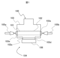
- FIG. 2 is a side view showing a schematic view of the column cartridge installed in a chromatograph.
- FIG. FIG. FIG. 2 is a top cross-sectional view showing the internal structure of the column cartridge.
- FIG. 2 is a front cross-sectional view showing the internal structure of the column cartridge.
- a liquid chromatograph is used as an example of a column cartridge, but the present invention is not limited to this and can also be applied to other chromatographs such as a high performance liquid chromatograph (HPLC), an ultra-high performance liquid chromatograph (UHPLC), and a gas chromatograph (GC).
- HPLC high performance liquid chromatograph
- UHPLC ultra-high performance liquid chromatograph
- GC gas chromatograph
- FIG. 1 is a side view showing a schematic diagram of a column cartridge installed in a chromatograph in a mass spectrometer.
- a sample mobile phase
- pretreatment such as purification/concentration in a pretreatment section (not shown)
- a delivery mechanism such as purification/concentration in a pretreatment section (not shown)
- the chromatograph 104 includes an upstream piping 105a, a downstream piping 105b, a heating mechanism 106, and a column cartridge 100.
- the upstream piping 105a supplies the sample to the separation column 101 of the column cartridge 100.
- the downstream piping 105b discharges the sample that has passed through the separation column 101.
- the heating mechanism 106 contacts the heat transfer body 102 of the column cartridge 100, thereby controlling the temperature of the separation column 101 via the heat transfer body 102.
- the heating mechanism 106 includes a heat transfer part that contacts the bottom surface (heat receiving surface) of the heat transfer body 102 from below, a heater that serves as a heat source for heating the heat transfer part, and a mechanism for moving the heat transfer part in the vertical direction, but only the heat transfer part is shown in FIG. 1.
- the column cartridge 100 is detachably attached to the heating mechanism 106 of the chromatograph 104.
- the column cartridge 100 is composed of a separation column 101, a heat transfer body 102, and a housing 103.
- Separation column 101 contains, for example, a packing material with an inner diameter of 1.0 mm, a length of 50 mm, and a particle diameter of 2.6 mm as a stationary phase.
- Separation modes available for separation column 101 include reversed phase mode, normal phase mode, molecular weight fractionation mode, HILIC (Hydrophilic Interaction Liquid Chromatography) mode, and antigen-antibody reaction mode.
- the heat transfer body 102 is provided so as to wrap around the outer periphery of the separation column 101, and has a protruding portion 102a that protrudes downward toward the heating mechanism 106.
- the heat transfer body 102 plays a role in transferring heat from the heating mechanism 106 to the separation column 101 by contacting the protruding portion 102a with the heat transfer portion of the heating mechanism 106.
- aluminum is used as the material for the heat transfer body 102, but this is not limited to this, and any material with high thermal conductivity, such as copper or nickel, may be used.
- the heat transfer body 102 is made of a material that can withstand corrosion by chemicals, or that the heat transfer body 102 is subjected to a surface treatment.
- the housing 103 contains the separation column 101 and the heat transfer body 102, and is mainly made of a resin material.
- the housing 103 also has a piping connection section 103e (opening) for connecting piping to the separation column 101, and a heat transfer connection section 103d (opening) for contacting the heat transfer body 102 with the heat transfer section of the heating mechanism 106.
- the upstream piping 105a, downstream piping 105b, and heating mechanism 106 are automatically detached from the column cartridge 100, for example by the operator pressing a specific button to indicate the start of the operation.
- the operator grasps the column cartridge 100 (specifically, the gripping portion 103c, described below) and pulls it out upward.
- the column cartridge 100 may be automatically pushed upward by pressing a specific button.
- the operator when replacing the separation column 101 and attaching it to the chromatograph 104, the operator himself fits the column cartridge 100 from above. After that, for example, the operator presses a specific button to indicate completion of the work, and the upstream piping 105a and downstream piping 105b are automatically connected to the separation column 101, and the heating mechanism 106 automatically comes into contact with the heat transfer body 102. Note that the completion of the work of fitting the column cartridge 100 may be automatically detected by a sensor or the like instead of by pressing a button.
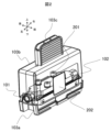
- Figure 2 is a top perspective view showing the exterior of the column cartridge
- Figure 3 is a bottom perspective view showing the exterior of the column cartridge.
- the separation column 101 is fixed to the heat transfer body 102 by a fixing screw 201, but this is not limited thereto.
- the separation column 101 and the heat transfer body 102 may both be provided with uneven shapes and fixed by engaging them.
- the heat transfer body 102 is supported by a housing 103, and the specific support structure will be described later with reference to FIG. 4 and FIG. 5.
- the housing 103 is configured to enclose the heat transfer body 102 and the separation column 101 by combining two separate members, that is, an upper housing 103b and a lower housing 103a.
- the above-mentioned pipe connection portions 103e are formed on both the left and right sides of the housing 103 by the lower end of the upper housing 103b and the upper end of the lower housing 103a.
- the upper surface of the upper housing 103b is provided with a gripping portion 103c that protrudes upward, and when removing or installing the separation column 101, the operator can insert or remove the column cartridge while gripping the gripping portion 103c.
- an RFID tag 202 on which information about the separation column 101 is written is attached to the side (front) of the upper housing 103b, and by reading this, the information about the separation column 101 can be managed. Note that what is attached to the upper housing 103b is not limited to the RFID tag 202, and other identification information such as a label with a printed barcode may also be used.
- an opening is formed on the bottom surface of the lower housing 103a, and this opening becomes the heat transfer connection part 103d.
- the protrusion part 102a of the heat transfer body 102 penetrates the heat transfer connection part 103d and is exposed downward, realizing contact with the heat transfer part of the heating mechanism 106.
- the opening area of the heat transfer connection part 103d is equal to the cross-sectional area of the protrusion part 102a and smaller than the cross-sectional area of the main body part of the heat transfer body 102 excluding the protrusion part 102a, so that the thermal influence that the heat transfer body 102 and the separation column 101 receive from the outside air is minimized.
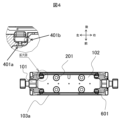
- Figure 4 is a top cross-sectional view showing the internal structure of the column cartridge.
- first supports 401 that support the four corners of the heat transfer body 102 are provided inside the lower housing 103a.
- Each first support 401 also has a front-rear support part 401a that regulates the front-rear position of the heat transfer body 102, and a left-right support part 401b that regulates the left-right position of the heat transfer body 102. Therefore, the position of the heat transfer body 102 in the horizontal direction (the direction perpendicular to the protruding direction of the protruding part 102a) is regulated within the lower housing 103a.
- a gap 601 is formed between the heat transfer body 102 and the lower housing 103a at positions other than the first support parts 401.
- This gap 601 forms an air layer between the heat transfer body 102 and the lower housing 103a, and therefore serves as a heat insulating layer.
- the heat of the heating mechanism 106 is not easily transmitted to the lower housing 103a.
- the tip of the first support 401 (the contact surface with the heat transfer body 102) is formed, for example, in a curved shape in order to reduce the contact area.
- the dimension of the gap 601, i.e., the distance between the lower housing 103a and the heat transfer body 102 at a position excluding the first support 401 is preferably 0.5 mm or more. This makes it possible to improve the insulation performance by the air layer.
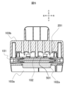
- FIG. 5 is a front cross-sectional view showing the internal structure of the column cartridge.
- a second support part 501 extending downward is provided at the center of the inside of the upper housing 103b.
- the horizontal position of the heat transfer body 102 is regulated by the first support part 401. Therefore, the tip of the second support part 501 can regulate the vertical position of the heat transfer body 102 simply by pressing the center of the upper surface of the heat transfer body 102, which is the opposite side to the protruding part 102a, at one point downward where the heat transfer connection part 103d and the heating mechanism 106 are located.
- the axis of the separation column 101 can be aligned with the upstream pipe 105a and the downstream pipe 105b.
- the lower surface of the protruding portion 102a of the heat transfer body 102 can be brought into close contact with the upper surface of the heat transfer portion of the heating mechanism 106, making it possible to accurately control the temperature of the separation column 101. If the tip of the second support portion 501 is also formed into a curved shape like the first support portion 401, the contact area with the heat transfer body 102 is reduced, and the transfer of heat from the heat transfer body 102 to the upper housing 103b can be suppressed.
- the heat transfer body 102 protrudes downward and contacts the heating mechanism 106 located below the separation column 101, but the heat transfer body 102 may protrude laterally (horizontally) and contact the heating mechanism 106 located to the side of the separation column 101.
- the heat transfer connection part 103d (opening) is formed on the side, and the second support part 501 extends toward the side.
- the present invention is not limited to the above-mentioned embodiment, but includes various modifications and combinations. Furthermore, the present invention is not limited to those having all the configurations described in the above-mentioned embodiment, but also includes those in which some of the configurations are omitted.
- 100...column cartridge 101...separation column, 102...heat transfer body, 102a...protrusion, 103...housing, 103a...lower housing, 103b...upper housing, 103c...gripping part, 103d...heat transfer connection part, 103e...piping connection part, 104...chromatograph, 105a...upstream piping, 105b...downstream piping, 106...heating mechanism, 201...fixing screw, 202...RFID tag, 401...first support part, 401a...front-rear support part, 401b...left-right support part, 501...second support part, 601...gap.
Landscapes
- Physics & Mathematics (AREA)
- Health & Medical Sciences (AREA)
- Life Sciences & Earth Sciences (AREA)
- Chemical & Material Sciences (AREA)
- Analytical Chemistry (AREA)
- Biochemistry (AREA)
- General Health & Medical Sciences (AREA)
- General Physics & Mathematics (AREA)
- Immunology (AREA)
- Pathology (AREA)
- Sampling And Sample Adjustment (AREA)
- Other Investigation Or Analysis Of Materials By Electrical Means (AREA)
Priority Applications (3)
| Application Number | Priority Date | Filing Date | Title |
|---|---|---|---|
| EP24807051.8A EP4711760A1 (en) | 2023-05-12 | 2024-04-30 | Column cartridge and analyzer |
| CN202480013789.6A CN120659997A (zh) | 2023-05-12 | 2024-04-30 | 柱盒及分析装置 |
| JP2025520502A JPWO2024237097A1 (cg-RX-API-DMAC7.html) | 2023-05-12 | 2024-04-30 |
Applications Claiming Priority (2)
| Application Number | Priority Date | Filing Date | Title |
|---|---|---|---|
| JP2023079384 | 2023-05-12 | ||
| JP2023-079384 | 2023-05-12 |
Publications (1)
| Publication Number | Publication Date |
|---|---|
| WO2024237097A1 true WO2024237097A1 (ja) | 2024-11-21 |
Family
ID=93519058
Family Applications (1)
| Application Number | Title | Priority Date | Filing Date |
|---|---|---|---|
| PCT/JP2024/016741 Ceased WO2024237097A1 (ja) | 2023-05-12 | 2024-04-30 | カラムカートリッジ及び分析装置 |
Country Status (4)
| Country | Link |
|---|---|
| EP (1) | EP4711760A1 (cg-RX-API-DMAC7.html) |
| JP (1) | JPWO2024237097A1 (cg-RX-API-DMAC7.html) |
| CN (1) | CN120659997A (cg-RX-API-DMAC7.html) |
| WO (1) | WO2024237097A1 (cg-RX-API-DMAC7.html) |
Citations (6)
| Publication number | Priority date | Publication date | Assignee | Title |
|---|---|---|---|---|
| JPH04216917A (ja) * | 1990-03-03 | 1992-08-07 | Dipl Ing Herbert Gunther Gmbh | ホットランナ−装置 |
| JP2014521983A (ja) * | 2011-08-19 | 2014-08-28 | ウオーターズ・テクノロジーズ・コーポレイシヨン | 液体クロマトグラフィーに使用されるマルチゾーン熱システムを備えたカラムマネージャ |
| JP2014202508A (ja) * | 2013-04-02 | 2014-10-27 | 株式会社島津製作所 | カラムユニット及びそのカラムユニットを備えたガスクロマトグラフ装置 |
| WO2017199335A1 (ja) * | 2016-05-17 | 2017-11-23 | 株式会社日立ハイテクノロジーズ | 分離カラム接続装置、接続方法及び分析システム |
| JP2019511727A (ja) * | 2016-04-15 | 2019-04-25 | ウオーターズ・テクノロジーズ・コーポレイシヨン | クロマトグラフィカラムを熱的に絶縁するための技術 |
| WO2020175651A1 (ja) | 2019-02-27 | 2020-09-03 | 株式会社日立ハイテク | 分析装置のカラムオーブン |
-
2024
- 2024-04-30 WO PCT/JP2024/016741 patent/WO2024237097A1/ja not_active Ceased
- 2024-04-30 JP JP2025520502A patent/JPWO2024237097A1/ja active Pending
- 2024-04-30 EP EP24807051.8A patent/EP4711760A1/en active Pending
- 2024-04-30 CN CN202480013789.6A patent/CN120659997A/zh active Pending
Patent Citations (6)
| Publication number | Priority date | Publication date | Assignee | Title |
|---|---|---|---|---|
| JPH04216917A (ja) * | 1990-03-03 | 1992-08-07 | Dipl Ing Herbert Gunther Gmbh | ホットランナ−装置 |
| JP2014521983A (ja) * | 2011-08-19 | 2014-08-28 | ウオーターズ・テクノロジーズ・コーポレイシヨン | 液体クロマトグラフィーに使用されるマルチゾーン熱システムを備えたカラムマネージャ |
| JP2014202508A (ja) * | 2013-04-02 | 2014-10-27 | 株式会社島津製作所 | カラムユニット及びそのカラムユニットを備えたガスクロマトグラフ装置 |
| JP2019511727A (ja) * | 2016-04-15 | 2019-04-25 | ウオーターズ・テクノロジーズ・コーポレイシヨン | クロマトグラフィカラムを熱的に絶縁するための技術 |
| WO2017199335A1 (ja) * | 2016-05-17 | 2017-11-23 | 株式会社日立ハイテクノロジーズ | 分離カラム接続装置、接続方法及び分析システム |
| WO2020175651A1 (ja) | 2019-02-27 | 2020-09-03 | 株式会社日立ハイテク | 分析装置のカラムオーブン |
Non-Patent Citations (1)
| Title |
|---|
| See also references of EP4711760A1 |
Also Published As
| Publication number | Publication date |
|---|---|
| CN120659997A (zh) | 2025-09-16 |
| JPWO2024237097A1 (cg-RX-API-DMAC7.html) | 2024-11-21 |
| EP4711760A1 (en) | 2026-03-18 |
Similar Documents
| Publication | Publication Date | Title |
|---|---|---|
| US9897576B2 (en) | Gas chromatography device | |
| EP3933400B1 (en) | Column oven of analyzing device | |
| US20130055791A1 (en) | Sample trapping method and sample trapping apparatus | |
| JP3419703B2 (ja) | 温度制御されたインジェクタを具備しているガスクロマトグラフィ装置 | |
| JP2010048554A (ja) | カラム温度監視装置及びクロマトグラフ装置 | |
| US8808629B2 (en) | Transfer unit for analysis devices | |
| EP4711760A1 (en) | Column cartridge and analyzer | |
| JP2009121937A (ja) | クロマトグラフ装置及びセンサ | |
| WO2022131075A1 (ja) | 液体クロマトグラフのカラム接続方法及び液体クロマトグラフ | |
| JP4701855B2 (ja) | ガスクロマトグラフ質量分析装置 | |
| JP4882025B2 (ja) | 高温マイクロ波クロマトグラフィーに使用する加熱式移送ライン | |
| JP2024103771A (ja) | 分析装置のカラムカートリッジ | |
| JP6540522B2 (ja) | ガスクロマトグラフ | |
| US12320822B2 (en) | Evaporator for a thermogravimetric analyzer | |
| JP3846013B2 (ja) | 液体クロマトグラフ装置 | |
| WO2022224539A1 (ja) | クロマトグラフ | |
| Chen | A brief review of interfacing supercritical fluid chromatography with mass spectrometry | |
| WO2020250315A1 (ja) | 超臨界流体装置用移動相温調装置および超臨界流体装置 | |
| EP1837650A1 (en) | Thermally conductive sheath for fluid conduit | |
| JP3651524B2 (ja) | ガス分析装置 | |
| JP2586554Y2 (ja) | 液体クロマトグラフ用反応槽 | |
| US10753912B2 (en) | Gas chromatograph | |
| JP2577345Y2 (ja) | ガスクロマトグラフ用恒温槽 | |
| JP2007132841A (ja) | 液体加温装置 | |
| JP2008232799A (ja) | 熱分解ガスクロマトグラフ装置 |
Legal Events
| Date | Code | Title | Description |
|---|---|---|---|
| 121 | Ep: the epo has been informed by wipo that ep was designated in this application |
Ref document number: 24807051 Country of ref document: EP Kind code of ref document: A1 |
|
| ENP | Entry into the national phase |
Ref document number: 2025520502 Country of ref document: JP Kind code of ref document: A |
|
| WWE | Wipo information: entry into national phase |
Ref document number: 2025520502 Country of ref document: JP |
|
| WWE | Wipo information: entry into national phase |
Ref document number: 202480013789.6 Country of ref document: CN |
|
| WWP | Wipo information: published in national office |
Ref document number: 202480013789.6 Country of ref document: CN |
|
| WWE | Wipo information: entry into national phase |
Ref document number: 2024807051 Country of ref document: EP |
|
| NENP | Non-entry into the national phase |
Ref country code: DE |
|
| ENP | Entry into the national phase |
Ref document number: 2024807051 Country of ref document: EP Effective date: 20251212 |
|
| ENP | Entry into the national phase |
Ref document number: 2024807051 Country of ref document: EP Effective date: 20251212 |
|
| ENP | Entry into the national phase |
Ref document number: 2024807051 Country of ref document: EP Effective date: 20251212 |
|
| ENP | Entry into the national phase |
Ref document number: 2024807051 Country of ref document: EP Effective date: 20251212 |
|
| ENP | Entry into the national phase |
Ref document number: 2024807051 Country of ref document: EP Effective date: 20251212 |
|
| ENP | Entry into the national phase |
Ref document number: 2024807051 Country of ref document: EP Effective date: 20251212 |
|
| ENP | Entry into the national phase |
Ref document number: 2024807051 Country of ref document: EP Effective date: 20251212 |
|
| ENP | Entry into the national phase |
Ref document number: 2024807051 Country of ref document: EP Effective date: 20251212 |
|
| ENP | Entry into the national phase |
Ref document number: 2024807051 Country of ref document: EP Effective date: 20251212 |
|
| WWP | Wipo information: published in national office |
Ref document number: 2024807051 Country of ref document: EP |