WO2024236692A1 - 直刃包丁及び直刃包丁の製造方法 - Google Patents
直刃包丁及び直刃包丁の製造方法 Download PDFInfo
- Publication number
- WO2024236692A1 WO2024236692A1 PCT/JP2023/018111 JP2023018111W WO2024236692A1 WO 2024236692 A1 WO2024236692 A1 WO 2024236692A1 JP 2023018111 W JP2023018111 W JP 2023018111W WO 2024236692 A1 WO2024236692 A1 WO 2024236692A1
- Authority
- WO
- WIPO (PCT)
- Prior art keywords
- blade
- cutting edge
- grooves
- straight
- knife
- Prior art date
- Legal status (The legal status is an assumption and is not a legal conclusion. Google has not performed a legal analysis and makes no representation as to the accuracy of the status listed.)
- Ceased
Links
Images




Classifications
-
- B—PERFORMING OPERATIONS; TRANSPORTING
- B26—HAND CUTTING TOOLS; CUTTING; SEVERING
- B26B—HAND-HELD CUTTING TOOLS NOT OTHERWISE PROVIDED FOR
- B26B9/00—Blades for hand knives
Definitions
- This disclosure relates to straight blade knives and methods for manufacturing straight blade knives.
- Some straight blade knives have multiple through holes or multiple recesses in the blade to prevent cutting pieces from sticking to the blade, i.e., to make it easier to cut away (see, for example, Patent Document 1).
- first recesses are provided at intervals in the length direction of the blade.
- second recesses are provided between the first recesses on the blade plate surface. The second recesses are smaller in size in the length direction of the blade than the first recesses, larger in size in the width direction of the blade, and deeper than the first recesses.
- a straight blade knife having a blade with a cutting edge, The blade has a first surface and a second surface opposite the first surface, The first surface is A cutting blade including the cutting edge; A plurality of grooves adjacent to the cutting edge in the width direction of the blade and extending along a cross direction intersecting the length direction of the blade, The plurality of grooves are arranged adjacent to each other in the longitudinal direction, A ridge portion is formed between adjacent grooves, The ridge portion is formed only by the inner surfaces of the recessed grooves.
- Straight blade knife having a blade with a cutting edge, The blade has a first surface and a second surface opposite the first surface, The first surface is A cutting blade including the cutting edge; A plurality of grooves adjacent to the cutting edge in the width direction of the blade and extending along a cross direction intersecting the length direction of the blade, The plurality of grooves are arranged adjacent to each other in the longitudinal direction, A ridge portion is formed between adjacent grooves, The ridge portion is formed only by the inner surfaces of the recessed grooves.
- the above-mentioned multiple grooves are provided on the first surface of the blade.
- the ridges formed between adjacent grooves are formed only by the inner surfaces of the grooves. Therefore, there are no flat portions between the grooves. This reduces the contact area of the first surface that comes into contact with the cut pieces of the object to be cut, thereby preventing the cut pieces of the object from adhering to the first surface. This improves the ease of cutting and separating.
- the cut pieces of the object to be cut are prevented from adhering to the first surface over the entire width direction of the blade, thereby further improving the ease of cutting and separating.
- the plurality of grooves are formed only on the first surface.
- a method for producing a straight blade knife according to any one of aspects 1 and 3, A first step of forming a plurality of concave blades extending along the transverse direction and constituting a wavy cutting edge on a target surface of a blade workpiece corresponding to the first surface of the blade; and a second step of grinding a portion of the target surface including the wavy cutting edge to form the cutting edge and to form the recessed groove from the recessed blade.
- a method for manufacturing a straight blade knife A method for manufacturing a straight blade knife.
- the multiple concave blades are formed on the target surface of the blade workpiece.
- the portion of the target surface that includes the wavy cutting edge is ground to form a cutting edge with a straight cutting edge, and a concave groove is formed from the concave blade. This allows the straight blade knife to be manufactured.
- FIG. 1 is a side view showing a first surface of a straight blade knife of one embodiment.
- FIG. 2 is a side view showing the second surface of the straight blade knife of FIG.
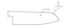
- FIG. 3 is a cross-sectional view taken along line 3-3 of FIG. 4A is a side view of a blade workpiece illustrating a manufacturing process for the straight blade knife of FIG. 1.
- FIG. 4B is a side view of a blade workpiece illustrating a manufacturing process of the straight blade knife of FIG.
- FIG. 5 is a side view showing a first surface of the straight blade knife of the first modified example.
- FIG. 6 is a side view showing a first surface of a straight blade knife of a second modified example.
- FIG. 7 is a side view showing a first surface of a straight blade knife of a third modified example.
- the straight blade knife for right-handed use will be described.
- the straight blade knife includes a blade 10 having a cutting edge 13 and a back portion 14 , a ferrule 31 , and a handle 32 .
- the blade 10 has a first surface 11 and a second surface 12 located opposite the first surface 11.
- the ridge 14 is an edge of the blade 10 located opposite the cutting edge 13 in the width direction W.
- the blade 10 has a cutting edge 21 and a jaw 22.
- the cutting edge 21 is located at the tip of the blade 10 in the length direction L.
- the jaw 22 is located at the base end of the cutting edge 13 in the length direction L.
- the first surface 11 has a cutting edge 15 including a cutting edge 13 and a plurality of grooves 16 .
- the multiple grooves 16 are adjacent to the cutting edge 15 in the width direction W of the blade 10 and extend along the width direction W.
- the width direction W corresponds to the intersecting direction that intersects with the length direction L of the blade 10.
- the multiple grooves 16 are lined up adjacent to one another in the length direction L.
- the multiple grooves 16 extend continuously in the width direction W from the cutting edge 15 to the ridge 14 of the blade 10.
- the multiple grooves 16 include a first groove 16A and a second groove 16B that is smaller in size in the longitudinal direction L than the first groove 16A.
- a pair of one first groove 16A and two second grooves 16B are alternately arranged in the longitudinal direction L.
- first groove 16A and the second groove 16B are not distinguished from each other, they will each simply be referred to as a groove 16.
- the groove 16 has, for example, an arc-shaped cross section.
- the radius of curvature of the arc that defines the first groove 16A is greater than the radius of curvature of the arc that defines the second groove 16B.
- a ridge 17 is formed between adjacent grooves 16.
- the ridge 17 is formed only by the inner sides of grooves 16.
- the ridge 17 is formed by the intersection of the inner sides of adjacent grooves 16.
- the grooves 16 and the ridge 17 extend parallel to each other.
- ⁇ Second surface 12> 2 and 3 the second surface 12 is flat. That is, the plurality of grooves 16 are formed only on the first surface 11.
- a steel plate of a predetermined thickness is punched into the outer shape of the blade 10 using a press to form a blade workpiece 110.
- a plurality of concave blades 116 that extend along the width direction W, which is the intersecting direction, and that form a wavy cutting edge 113 are formed on the target surface 111 of the blade workpiece 110 corresponding to the first surface 11 of the blade 10 (this is referred to as the first step).
- the plurality of concave blades 116 are formed by cutting.
- the portion 110A of the target surface 111 including the wavy cutting edge 113 is ground.
- the cutting edge 15 is formed and the concave groove 16 is formed from the concave edge 116 (this is referred to as the second step). In this way, the blade 10 is formed.
- a plurality of grooves 16 are provided on the first surface 11 of the blade 10.
- the ridges 17 formed between adjacent grooves 16 are formed only by the inner surfaces of the grooves 16. Therefore, there are no flat portions between the grooves 16. This reduces the contact area of the first surface 11 that comes into contact with the cut pieces of the object to be cut, thereby suppressing adhesion of the cut pieces of the object to the first surface 11. This improves the ease of cutting and separating.
- the first surface 11 of the blade 10 has a cutting edge 15 including a cutting edge 13, and a plurality of grooves 16.
- the plurality of grooves 16 are arranged adjacent to one another in the longitudinal direction L.
- a ridge portion 17 is formed between adjacent grooves 16.
- the ridge portion 17 is formed only by the inner surfaces of the grooves 16.
- the multiple grooves 16 extend continuously in the width direction W from the cutting edge 15 to the ridge 14 of the blade 10 .
- This configuration prevents the cut pieces of the object from adhering to the first surface 11 across the entire width direction W of the blade 10. This further improves the ease of cutting.
- the manufacturing method of a straight blade knife includes a first step and a second step. According to this configuration, the plurality of concave blades 116 are formed on the target surface 111 of the blade workpiece 110. Next, by grinding the portion 110A of the target surface 111 including the wavy cutting edge 113, the cutting edge 15 having the straight cutting edge 13 is formed, and the concave groove 16 is formed from the concave blade 116. This allows the straight blade knife to be manufactured.
- the multiple grooves 16 are not limited to those that extend continuously from the cutting edge 15 to the ridge 14 of the blade 10 in the width direction W.
- the multiple grooves 16 may extend continuously from the cutting edge 15 to a position midway between the cutting edge 13 and the ridge 14 in the width direction W.
- a flat portion 18 is formed between the multiple grooves 16 and the ridge 14 of the blade 10.
- the present invention can also be applied to a straight blade knife, a so-called vegetable knife, in which the cutting edge 13 extends in a straight line.
- a straight blade knife a so-called vegetable knife, in which the cutting edge 13 extends in a straight line.
- the sizes of the multiple grooves 16 in the length direction L are all equal.
- the straight blade knife shown in FIG. 7 is manufactured by forming a plurality of grooves 16 extending along the width direction W on the first surface 11 of the straight blade knife shown in FIG. 6, and then forming a plurality of grooves extending along the length direction L and adjacent to each other in the width direction W.
- the grooves extending along the width direction W are divided by grooves extending along the length direction L
- the grooves extending along the length direction L are divided by grooves extending along the width direction W.
- This disclosure is not limited to the grooves 16 being formed over the entire length direction L of the blade 10.
- the grooves 16 do not necessarily extend along the width direction W, but may extend along a direction inclined with respect to the width direction W.
- a plurality of concave blades 116 may be formed on the target surface 111 of the blade workpiece 110 by etching or laser processing.
- a press may be used to form the concave blade 116 in the steel plate and punch the steel plate into the outer shape of the blade 10, thereby forming the blade workpiece 110 shown in FIG. 4B.
- the second step may be performed to form the cutting edge 15 with the straight cutting edge 13 and to form the concave groove 16 from the concave blade 116.
Landscapes
- Life Sciences & Earth Sciences (AREA)
- Forests & Forestry (AREA)
- Engineering & Computer Science (AREA)
- Mechanical Engineering (AREA)
- Knives (AREA)
Priority Applications (2)
| Application Number | Priority Date | Filing Date | Title |
|---|---|---|---|
| JP2024501151A JPWO2024236692A1 (https=) | 2023-05-15 | 2023-05-15 | |
| PCT/JP2023/018111 WO2024236692A1 (ja) | 2023-05-15 | 2023-05-15 | 直刃包丁及び直刃包丁の製造方法 |
Applications Claiming Priority (1)
| Application Number | Priority Date | Filing Date | Title |
|---|---|---|---|
| PCT/JP2023/018111 WO2024236692A1 (ja) | 2023-05-15 | 2023-05-15 | 直刃包丁及び直刃包丁の製造方法 |
Publications (1)
| Publication Number | Publication Date |
|---|---|
| WO2024236692A1 true WO2024236692A1 (ja) | 2024-11-21 |
Family
ID=93518831
Family Applications (1)
| Application Number | Title | Priority Date | Filing Date |
|---|---|---|---|
| PCT/JP2023/018111 Ceased WO2024236692A1 (ja) | 2023-05-15 | 2023-05-15 | 直刃包丁及び直刃包丁の製造方法 |
Country Status (2)
| Country | Link |
|---|---|
| JP (1) | JPWO2024236692A1 (https=) |
| WO (1) | WO2024236692A1 (https=) |
Citations (4)
| Publication number | Priority date | Publication date | Assignee | Title |
|---|---|---|---|---|
| JPS55133961U (https=) * | 1979-03-16 | 1980-09-22 | ||
| JPS566373U (https=) * | 1979-06-26 | 1981-01-20 | ||
| JP2001190864A (ja) * | 2000-01-14 | 2001-07-17 | Cassette-Feu Kk | 波刃包丁 |
| JP2006025928A (ja) | 2004-07-13 | 2006-02-02 | Fujitora Kogyo Kk | 包丁 |
Family Cites Families (5)
| Publication number | Priority date | Publication date | Assignee | Title |
|---|---|---|---|---|
| JPS4833668U (https=) * | 1971-08-21 | 1973-04-23 | ||
| JPS5140450U (https=) * | 1974-09-14 | 1976-03-25 | ||
| JPS59145367U (ja) * | 1983-03-16 | 1984-09-28 | マツク株式会社 | 冷凍物用庖丁 |
| JPS63158270U (https=) * | 1987-04-06 | 1988-10-17 | ||
| JP3005961U (ja) * | 1991-11-09 | 1995-01-17 | ガエ ヨング ジュング | 包 丁 |
-
2023
- 2023-05-15 JP JP2024501151A patent/JPWO2024236692A1/ja active Pending
- 2023-05-15 WO PCT/JP2023/018111 patent/WO2024236692A1/ja not_active Ceased
Patent Citations (4)
| Publication number | Priority date | Publication date | Assignee | Title |
|---|---|---|---|---|
| JPS55133961U (https=) * | 1979-03-16 | 1980-09-22 | ||
| JPS566373U (https=) * | 1979-06-26 | 1981-01-20 | ||
| JP2001190864A (ja) * | 2000-01-14 | 2001-07-17 | Cassette-Feu Kk | 波刃包丁 |
| JP2006025928A (ja) | 2004-07-13 | 2006-02-02 | Fujitora Kogyo Kk | 包丁 |
Also Published As
| Publication number | Publication date |
|---|---|
| JPWO2024236692A1 (https=) | 2024-11-21 |
Similar Documents
| Publication | Publication Date | Title |
|---|---|---|
| JP3720362B2 (ja) | 鋸刃の歯形及びそのための方法 | |
| US6532855B1 (en) | Saw blade having dimples formed by process of deforming blade body | |
| KR100511851B1 (ko) | 전기 면도기용 내부 칼날 제조 방법 | |
| JPS6099243A (ja) | 外科用やすり | |
| BR102012031162A2 (pt) | Lâmina de serra com projeção de formar dente | |
| US20120153062A1 (en) | Food grater | |
| JP2001522733A (ja) | 帯状または短冊状のカッタ | |
| WO2008044538A1 (en) | Outer blade for reciprocation-type electric shaver and method of producing the same | |
| JP3230143B2 (ja) | ロータリーダイカッター | |
| WO2024236692A1 (ja) | 直刃包丁及び直刃包丁の製造方法 | |
| JPH11508777A (ja) | 切断用具特にナイフ用の微細歯形 | |
| US6054671A (en) | Methods of making a chain saw guide bar with high wear resistance strips | |
| JP5184878B2 (ja) | ドリル | |
| JP7208674B2 (ja) | 刃物 | |
| JP4483190B2 (ja) | ロータリーダイ | |
| JP2000280374A (ja) | リード罫の形成用刃物 | |
| CN222199132U (zh) | 一种具有交错排列的切削缺口的圆锯片 | |
| JP4826227B2 (ja) | ロータリーダイ | |
| JP3469500B2 (ja) | 打抜き刃および打抜き刃物 | |
| JP2001334339A (ja) | タッピンねじ | |
| JP2004291128A (ja) | ロータリーダイ | |
| JPWO2024236692A5 (https=) | ||
| JP2000061724A (ja) | 金属板の剪断装置 | |
| JP5043227B2 (ja) | 丸のこ刃 | |
| KR20190064438A (ko) | 스크라이빙 휠 |
Legal Events
| Date | Code | Title | Description |
|---|---|---|---|
| WWE | Wipo information: entry into national phase |
Ref document number: 2024501151 Country of ref document: JP |
|
| ENP | Entry into the national phase |
Ref document number: 2023853629 Country of ref document: EP Effective date: 20240221 |
|
| NENP | Non-entry into the national phase |
Ref country code: DE |