WO2024232115A1 - 操舵操作入力装置およびステアバイワイヤ式の操舵装置 - Google Patents
操舵操作入力装置およびステアバイワイヤ式の操舵装置 Download PDFInfo
- Publication number
- WO2024232115A1 WO2024232115A1 PCT/JP2023/043103 JP2023043103W WO2024232115A1 WO 2024232115 A1 WO2024232115 A1 WO 2024232115A1 JP 2023043103 W JP2023043103 W JP 2023043103W WO 2024232115 A1 WO2024232115 A1 WO 2024232115A1
- Authority
- WO
- WIPO (PCT)
- Prior art keywords
- shaft
- operation input
- steering operation
- input device
- biasing member
- Prior art date
- Legal status (The legal status is an assumption and is not a legal conclusion. Google has not performed a legal analysis and makes no representation as to the accuracy of the status listed.)
- Ceased
Links
Images




Classifications
-
- B—PERFORMING OPERATIONS; TRANSPORTING
- B62—LAND VEHICLES FOR TRAVELLING OTHERWISE THAN ON RAILS
- B62D—MOTOR VEHICLES; TRAILERS
- B62D5/00—Power-assisted or power-driven steering
- B62D5/001—Mechanical components or aspects of steer-by-wire systems, not otherwise provided for in this maingroup
- B62D5/005—Mechanical components or aspects of steer-by-wire systems, not otherwise provided for in this maingroup means for generating torque on steering wheel or input member, e.g. feedback
-
- B—PERFORMING OPERATIONS; TRANSPORTING
- B62—LAND VEHICLES FOR TRAVELLING OTHERWISE THAN ON RAILS
- B62D—MOTOR VEHICLES; TRAILERS
- B62D1/00—Steering controls, i.e. means for initiating a change of direction of the vehicle
- B62D1/02—Steering controls, i.e. means for initiating a change of direction of the vehicle vehicle-mounted
- B62D1/16—Steering columns
-
- B—PERFORMING OPERATIONS; TRANSPORTING
- B62—LAND VEHICLES FOR TRAVELLING OTHERWISE THAN ON RAILS
- B62D—MOTOR VEHICLES; TRAILERS
- B62D5/00—Power-assisted or power-driven steering
- B62D5/001—Mechanical components or aspects of steer-by-wire systems, not otherwise provided for in this maingroup
-
- B—PERFORMING OPERATIONS; TRANSPORTING
- B62—LAND VEHICLES FOR TRAVELLING OTHERWISE THAN ON RAILS
- B62D—MOTOR VEHICLES; TRAILERS
- B62D5/00—Power-assisted or power-driven steering
- B62D5/001—Mechanical components or aspects of steer-by-wire systems, not otherwise provided for in this maingroup
- B62D5/003—Backup systems, e.g. for manual steering
-
- B—PERFORMING OPERATIONS; TRANSPORTING
- B62—LAND VEHICLES FOR TRAVELLING OTHERWISE THAN ON RAILS
- B62D—MOTOR VEHICLES; TRAILERS
- B62D5/00—Power-assisted or power-driven steering
- B62D5/001—Mechanical components or aspects of steer-by-wire systems, not otherwise provided for in this maingroup
- B62D5/005—Mechanical components or aspects of steer-by-wire systems, not otherwise provided for in this maingroup means for generating torque on steering wheel or input member, e.g. feedback
- B62D5/006—Mechanical components or aspects of steer-by-wire systems, not otherwise provided for in this maingroup means for generating torque on steering wheel or input member, e.g. feedback power actuated
-
- B—PERFORMING OPERATIONS; TRANSPORTING
- B62—LAND VEHICLES FOR TRAVELLING OTHERWISE THAN ON RAILS
- B62D—MOTOR VEHICLES; TRAILERS
- B62D5/00—Power-assisted or power-driven steering
- B62D5/04—Power-assisted or power-driven steering electrical, e.g. using an electric servo-motor connected to, or forming part of, the steering gear
Definitions
- the present invention relates to a steering operation input device and a steer-by-wire type steering device.
- the steering operation input device of Patent Document 1 has a first biasing member that generates a reaction force against one rotation direction of a steering operation input member of the steering device, and a second biasing member that generates a reaction force against the other rotation direction opposite to the one rotation direction of the steering operation input member. Switching between reaction force generation by the first biasing member and the second biasing member is performed via a linear motion conversion device that converts the rotational force input from the steering operation input member into linear motion.
- the steering operation input device of Patent Document 1 is provided with a dedicated biasing member for generating a reaction force for each rotation direction of the steering operation input member, which increases the number of parts in the steering operation input device, resulting in an increase in the manufacturing cost of the steering operation input device.
- the present invention was devised in consideration of the current situation, and one of its objectives is to provide a steering operation input device that can reduce manufacturing costs.
- the steering operation input device has a biasing member that applies a biasing force against the rotation of the shaft, and this biasing member includes a first biasing member that applies a biasing force to the shaft regardless of the rotation direction of the shaft, and a second biasing member that is attached in a preloaded state and applies a biasing force to the shaft regardless of the rotation direction of the shaft after the first biasing member applies a biasing force.
- the present invention makes it possible to reduce the manufacturing costs of steering operation input devices.
- FIG. 1 is a schematic diagram of a steer-by-wire type steering system to which a steering operation input device of the present invention is applied.
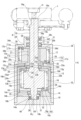
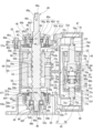
- 1 is a vertical sectional view of a steering operation input device according to a first embodiment.
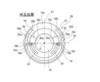
- 11 is an explanatory diagram showing the positional relationship between a first torsion spring and a first and second arcuate grooves of the first shaft in a neutral position when viewed in the axial direction of the first shaft;
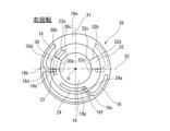
- FIG. 13 is an explanatory diagram showing the positional relationship between a first torsion spring and the first and second arcuate grooves of the first shaft when rotated clockwise from a neutral position;
- FIG. 11 is an explanatory diagram showing the positional relationship between a first torsion spring and the first and second arcuate grooves of the first shaft when rotated clockwise from a neutral position;
- FIG. 13 is an explanatory diagram showing the positional relationship between a first torsion spring and the first and second arcuate grooves of the first shaft when rotated clockwise
- FIG. 13 is an explanatory diagram showing the positional relationship between a first torsion spring and the first and second arcuate grooves of the first shaft when rotated left from a neutral position;
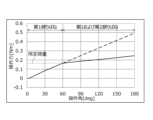
- FIG. 4 is a graph showing an operation force relative to an operation angle in the first embodiment.
- FIG. 11 is a vertical sectional view of a steering operation input device according to a second embodiment. (a) is an explanatory diagram showing the steering operation input device when the third shaft is rotated 180 degrees to the left from the neutral position, (b) is an explanatory diagram showing the steering operation input device when the third shaft is rotated 60 degrees to the left from the neutral position, and (c) is an explanatory diagram showing the steering operation input device in the neutral position.
- (a) is an explanatory diagram showing the steering operation input device in the neutral position
- (b) is an explanatory diagram showing the steering operation input device when the third shaft is rotated 60 degrees to the right from the neutral position
- (c) is an explanatory diagram showing the steering operation input device when the third shaft is rotated 180 degrees to the right from the neutral position.
- 13 is a graph showing an operation force relative to an operation angle in the third embodiment.
- FIG. 1 is a schematic diagram of a steer-by-wire type steering system to which a steering operation input device of the present invention is applied.
- a steer-by-wire steering device is configured so that the steering input device (described below), in which the driver inputs steering input via a dial 1, which is a steering input member used to perform steering operations, and the steering mechanism 3, which steers a pair of steerable wheels 2, 2, are mechanically separated.
- the dial 1 is fixed to one end of the shaft 4, which is a column shaft provided in the steering operation input device.
- another steering operation input member for example a steering wheel, may be fixed to one end of the shaft 4.
- An operation angle sensor 6 is provided on the outer periphery of the shaft 4, which detects the operation angle (steering angle) of the shaft 4 associated with the driver's steering operation.
- the operation angle signal detected by the operation angle sensor 6 is transmitted to the control device 7.
- various detection signals other than the steering angle signal are transmitted to the control device 7 by an external sensor 8.
- the control device 7 controls the electric motor 9 provided in the steering mechanism 3 based on the steering angle signal, a steering amount signal described below, and various detection signals.
- the steering mechanism 3 includes a steering shaft 10, a pair of tie rods 11, 11 connected to both ends of the steering shaft 10 and steering the pair of steered wheels 2, 2, an electric motor 9 that controls the steering operation of the steering shaft 10, and a steering amount sensor 12 that detects a steering amount signal of the steering shaft 10.
- the steering amount signal detected by the steering amount sensor 12 is sent to the control device 7.
- FIG. 2 is a longitudinal cross-sectional view of the steering operation input device of the first embodiment.
- the operation angle sensor 6 is omitted in order to simplify the drawing.
- FIG. 3 is an explanatory diagram showing the positional relationship between the first torsion spring 16 and the first arc groove 23 and the second arc groove 24 of the first shaft 19 in the neutral position when viewed from the axial direction of the first shaft 19.
- the first arc groove 23 and the second arc groove 24 are shown as being formed on the same plane, but in reality, the first arc groove 23 is formed in one axial end face 19h, while the second arc groove 24 is formed in the other axial end face 19i, which is shifted from the one axial end face 19h toward the other end 19b of the first shaft 19.
- FIG. 3 is an explanatory diagram showing the positional relationship between the first torsion spring 16 and the first arc groove 23 and the second arc groove 24 of the first shaft 19 in the neutral position when viewed from the axial direction of the first shaft 19.
- FIG. 4 is an explanatory diagram showing the positional relationship between the first torsion spring 16 and the first arc groove 23 and the second arc groove 24 of the first shaft 19 when rotated clockwise from the neutral position.
- FIG. 5 is an explanatory diagram showing the positional relationship between the first torsion spring 16 and the first arc groove 23 and the second arc groove 24 of the first shaft 19 when rotated counterclockwise from the neutral position.
- FIG. 6 is a graph showing the operating force versus the operating angle in the first embodiment.
- the steering operation input device includes a shaft 4, a connecting member 13, a connecting member cover 14, a housing 15, a first torsion spring (first biasing member) 16, a second torsion spring (second biasing member) 17, and a blocking member 18.
- the shaft 4 has a first shaft 19 to which the operating force from the dial 1 is transmitted and which rotates around the rotation axis O, and a second shaft 20 connected to the first shaft 19 via a connecting member 13 and a first torsion spring 16.
- first shaft 19 to which the operating force from the dial 1 is transmitted and which rotates around the rotation axis O
- second shaft 20 connected to the first shaft 19 via a connecting member 13 and a first torsion spring 16.
- the center line that passes through the rotation axis O of the first shaft 19 and divides the first shaft 19 into left and right is defined as the "first center line X1", and further, the center line that passes through the rotation axis O of the first shaft 19 and is perpendicular to the first center line X1 is defined as the "second center line X2". Note that the direction along the second center line X2 in FIG. 3 coincides with the left-right direction in FIG. 2.
- the shaft 4 has a first small diameter portion 19c which is a shaft portion located on the one end 19a side, a medium diameter portion 19d which is formed integrally with the first small diameter portion 19c and is a shaft portion with a larger diameter than the first small diameter portion 19c, a large diameter portion 19e which is formed integrally with the medium diameter portion 19d and is a shaft portion with a larger diameter than the medium diameter portion 19d, and a second small diameter portion 19f which is formed integrally with the large diameter portion 19e and is a shaft portion with a smaller diameter than the large diameter portion 19e.
- a D-cut portion 19g is formed on the outer periphery of the first small diameter portion 19c on the one end 19a side for engagement with the dial 1.
- the D-cut portion 19g is fixed to the dial 1, for example, via a well-known key connection.
- a first ball bearing 21, which is a bearing that rotatably supports the first small diameter portion 19c, is provided on the outer periphery of the axial center portion of the first small diameter portion 19c.
- a second ball bearing 22, which is a bearing that rotatably supports the first small diameter portion 19c is provided on the outer periphery of the axial end portion located on the other end 19b side of the first small diameter portion 19c.
- the large diameter portion 19e is a shaft portion around which the first torsion spring 16 is attached.
- the outer diameter of the large diameter portion 19e is set to be smaller than the inner diameter of the first torsion spring 16 when it is twisted and maximally compressed.
- the large diameter portion 19e is located on the one end 19a side and has an axial one end face 19h which is a continuous ring-shaped surface, and an axial other end face 19i which is located on the other end 19b side and is also a continuous ring-shaped surface.
- a first arc groove 23 is formed in an arc shape concentric with the outer periphery of the first shaft 19 at a position near the outer periphery of the first small diameter portion 19c of the first shaft 19 on the axial end face 19h on the side where the D-cut portion 19g of the first small diameter portion 19c of the first shaft 19 is provided.
- the first arc groove 23 is located to the left of the first center line X1 and extends in an arc shape at a predetermined angle, 180 degrees in this embodiment, counterclockwise from the second center line X2.
- the first arc groove 23 may be formed so as to continue in an arc shape at any angle other than 180 degrees.
- the first arc groove 23 has a first groove end portion 23a adjacent to the second center line X2 and a second groove end portion (not shown) on the opposite side of the first groove end portion 23a. As shown in FIG. 3, when the first torsion spring 16 is in a neutral state, the first bent portion 16e of the first spring end 16b (described later) of the first torsion spring 16 is located at the first groove end 23a of the first arc groove 23.
- a second arc groove 24 is formed in the other axial end face 19i near the outer periphery of the first shaft 19 and diagonally across the rotation axis O of the first shaft 19.
- the second arc groove 24 is concentric with the outer periphery of the first shaft 19 and has a shape similar to that of the first arc groove 23.
- the second arc groove 24 is located to the right of the first center line X1 and extends in an arc shape at a predetermined angle, 180 degrees in this embodiment, counterclockwise from the second center line X2.
- the second arc groove 24 may be formed so as to continue in an arc shape at any angle other than 180 degrees.
- the second arc groove 24 has a third groove end 24a adjacent to the second center line X2 and a fourth groove end (not shown) on the opposite side of the third groove end 24a. As shown in FIG. 3, when the first torsion spring 16 is in a neutral state, the second bent portion 16g of the second spring end 16c (described later) of the first torsion spring 16 is located at the third groove end 24a of the second arc groove 24.
- the second small diameter portion 19f also has a stepped reduced diameter portion 19j whose tip is formed in a stepped reduced diameter shape.
- the second shaft 20 is formed in a cylindrical shape with an outer diameter larger than the large diameter portion 19e of the first shaft 19.
- the second shaft 20 has a circular first through hole 20a in its center, into which the small diameter cylindrical portion 13a (described below) of the connecting member 13 is inserted with the first small diameter portion 19c of the first shaft 19 passing through.
- the second shaft 20 has an axial one end side end face 20b located on the one end 19a side, which is a continuous surface in the shape of a ring, and an axial other end side end face 20c located on the other end 19b side, which is a continuous surface in the shape of a ring.
- a third arc groove 27 is formed in a position on the axial one end side end face 20b near the outer periphery of the second shaft 20, forming an arc shape concentric with the outer periphery of the second shaft 20.
- the third arc groove 27 has a shape similar to that of the first arc groove 23, but is provided at a position outside the first arc groove 23 in the radial direction of the first shaft 19.
- the positional relationship between the third arc groove 27 and a third protrusion 36 described below when the second torsion spring 17 is in the neutral position is the same as the positional relationship between the first arc groove 23 and the first protrusion 30 when the first torsion spring 16 is in the neutral state (the positional relationship shown in FIG. 3).
- a fourth arc groove 28 is formed in a circular arc shape concentric with the outer periphery of the second shaft 20 on the other axial end side end face 20c opposite the side where the D-cut portion 19g of the large diameter portion 19e of the first shaft 19 is provided, toward the outer periphery of the second shaft 20.
- the fourth arc groove 28 has a shape similar to that of the second arc groove 24, but is provided at a position outside the second arc groove 24 in the radial direction of the first shaft 19.
- the positional relationship between the fourth arc groove 28 and a fourth protrusion 35 described below when the second torsion spring 17 is in the neutral position is the same as the positional relationship between the second arc groove 24 and a second protrusion 32 described below when the first torsion spring 16 is in the neutral state (the positional relationship shown in FIG. 3).
- the connecting member 13 is formed in a cylindrical shape from a metal material or resin.
- the connecting member 13 includes a small diameter cylindrical portion 13a, a large diameter cylindrical portion 13b, and a connecting portion 13c that connects the small diameter cylindrical portion 13a and the large diameter cylindrical portion 13b.
- the first small diameter portion 19c of the first shaft 19 penetrates the space inside the inner peripheral surface of the small diameter cylindrical portion 13a.
- the inner peripheral surface of the small diameter cylindrical portion 13a is separated from the outer peripheral surface of the first small diameter portion 19c through a small gap.
- a D-cut portion (not shown) is formed on the outer peripheral surface of the small diameter cylindrical portion 13a, and the D-cut portion is fixed to the first through hole 20a of the second shaft 20 through a known key connection.
- the first through hole 20a of the second shaft 20 may be fixed to the D-cut portion of the small diameter cylindrical portion 13a using a known screw connection. Also, instead of the D-cut portion, the first through hole 20a of the second shaft 20 may be fixed to the small diameter cylindrical portion 13a via a spline portion.
- the large diameter cylindrical portion 13b is cylindrical and has a larger diameter than the small diameter cylindrical portion 13a.
- the medium diameter portion 19d, the large diameter portion 19e, a part of the second small diameter portion 19f of the first shaft 19, and the first torsion spring 16 are housed inside the large diameter cylindrical portion 13b.
- the axial end portion at one end 19a of the large diameter cylindrical portion 13b is connected to the axial end portion at the other end 19b of the small diameter cylindrical portion 13a by the connecting portion 13c. Meanwhile, the opening surface of the other axial end portion at the other end 19b of the large diameter cylindrical portion 13b is covered by the connecting member cover 14.
- the joint portion 13c has a first annular extension portion 13d that extends from the outer periphery of the small diameter cylindrical portion 13a radially outward of the first shaft 19, a cylindrical protruding portion 13e that protrudes from the radial end of the first annular extension portion 13d toward the other end 19b, and a second annular extension portion 13f that extends from the outer periphery of the cylindrical protruding portion 13e radially outward of the first shaft 19.
- the space inside the inner circumferential surface of the cylindrical protruding portion 13e is the first bearing housing portion 29 that houses the second ball bearing 22, which is a bearing that rotatably supports the first small diameter portion 19c.
- a first protrusion 30 (shown by solid and dashed lines in FIG. 2) is formed on the surface 13g on the other end 19b side of the second annular expansion portion 13f near the first arc groove 23 of the large diameter portion 19e of the first shaft 19, protruding toward the large diameter portion 19e. More specifically, as shown in FIG. 3, the first protrusion 30 is provided at a position adjacent to the second center line X2 in an area to the left of the first center line X1 and above the second center line X2. As shown in FIG. 3, the first protrusion 30 is adjacent to the first groove end 23a of the first arc groove 23 when the first torsion spring 16 is in the neutral position.
- the width of the first protrusion 30 along the radial direction of the first shaft 19 is larger than the width of the first arc groove 23 along the radial direction of the first shaft 19.
- the first projection 30 has a first plane 30a along the second center line X2, a second plane 30b on the opposite side of the first plane 30a in the circumferential direction of the first shaft 19, a first arc surface 30c connecting the inner ends of the first plane 30a and the second plane 30b, and a second arc surface 30d connecting the outer ends of the first plane 30a and the second plane 30b.
- the first plane 30a of the first projection 30 is capable of abutting with a first inclined portion 16d of a first spring end 16b (described later) of the first torsion spring 16.
- the connecting member cover 14 is formed in a disk shape from a metal material or resin.
- a second through hole 14a is formed in the center of the connecting member cover 14 along the axial direction of the first shaft 19.
- the second through hole 14a is formed in a stepped shape with a reduced diameter from the one end 19a side to the other end 19b side via a step portion 14b that continues in an annular shape, and the space on the one end 19a side from the step portion 14b is the second bearing accommodating portion 31 that accommodates the third ball bearing 25 that rotatably supports the second small diameter portion 19f of the first shaft 19.
- a step portion 14c that continues in an annular shape is formed on the outer circumferential edge portion on the one end 19a side of the connecting member cover 14, and this step portion 14c accepts the other axial end portion on the other end 19b side of the large diameter cylindrical portion 13b of the connecting member 13.
- the other axial end portion on the other end 19b side of the large diameter cylindrical portion 13b is fixed to the step portion 14c.
- the surface of the connecting member cover 14 facing the blocking member 18 on the other end 19b side is separated from the surface 18b on the one end 19a side of the blocking member 18 via a small gap.
- a second protrusion 32 (shown by solid and dashed lines in FIG. 2) is formed protruding toward the large diameter portion 19e at a position near the second arc groove 24 of the large diameter portion 19e of the first shaft 19. More specifically, as shown in FIG. 3, the second protrusion 32 is provided at a position adjacent to the second center line X2 in an area to the right of the first center line X1 and above the second center line X2. As shown in FIG. 3, the second protrusion 32 is adjacent to the third groove end 24a of the second arc groove 24 when the first torsion spring 16 is in the neutral position.
- the second protrusion 32 has a shape similar to that of the first protrusion 30.
- the width of the second protrusion 32 along the radial direction of the first shaft 19 is larger than the width of the second arc groove 24 along the radial direction of the first shaft 19.
- the second protrusion 32 has a third plane 32a along the second center line X2, a fourth plane 32b on the opposite side of the third plane 32a in the circumferential direction of the first shaft 19, a third arc surface 32c connecting the inner ends of the third plane 32a and the fourth plane 32b, and a fourth arc surface 32d connecting the outer ends of the third plane 32a and the fourth plane 32b.
- the third plane 32a of the second protrusion 32 is capable of abutting with a second inclined portion 16f of a second spring end 16c (described later) of the first torsion spring 16.
- the housing 15 has a first housing 33 located on the other end 19b side and a second housing 34 located on the one end 19a side.
- the first housing 33 is formed of a metal material or resin into a cylindrical shape with a bottom.
- the first housing 33 accommodates the portion of the first shaft 19 closer to the other end 19b than the second ball bearing 22, a part of the joint portion 13c of the connecting member 13, the large diameter cylindrical portion 13b, the first torsion spring 16, and the connecting member cover 14.
- the first housing 33 has a bottom wall portion 33a in the shape of a circular plate, and a cylindrical peripheral wall portion 33b extending from the outer periphery of the bottom wall portion 33a to the other end 19b side.
- a third through hole 33c is formed in the center of the bottom wall portion 33a and penetrates along the axial direction of the first shaft 19.
- the joint portion 13c of the connecting member 13 with the first small diameter portion 19c of the first shaft 19 penetrating therethrough is inserted into the third through hole 33c.
- the inner circumferential surface of the third through hole 33c is spaced from the outer circumferential surface of the connecting portion 13c.
- a fourth protrusion 35 (shown by solid and dashed lines in FIG. 2) is formed on the surface 33d on the one end 19a side of the bottom wall portion 33a at a position near the fourth arc groove 28 of the second shaft 20 and protrudes toward the second shaft 20.
- the second housing 34 is formed of a metal material or resin into a cylindrical shape with a bottom.
- the second housing 34 accommodates a part of the first small diameter portion 19c of the first shaft 19, the small diameter cylindrical portion 13a of the connecting member 13, the second shaft 20, and the second torsion spring 17.
- the second housing 34 has a bottom wall portion 34a, a cylindrical peripheral wall portion 34b extending from the outer peripheral edge portion of the bottom wall portion 34a to the other end portion 19b side, and a cylindrical extension portion 34c extending from the center of the bottom wall portion 34a to the dial 1 side.
- a third protrusion 36 (shown by solid lines and dashed lines in FIG.
- a fourth through hole 34f is formed in the bottom wall portion 34a and the expansion portion 34c in the axial direction of the first shaft 19.
- the first small diameter portion 19c of the first shaft 19 is inserted into the fourth through hole 34f.
- a third bearing accommodating portion 37 which is a circular recess recessed from the surface 34d of the bottom wall portion 34a toward the one end 19a side, is formed in the bottom wall portion 34a and a part of the expansion portion 34c.
- the third bearing accommodating portion 37 accommodates the first ball bearing 21 that rotatably supports the first small diameter portion 19c of the first shaft 19.
- a continuous annular groove portion 34g is formed in the inner peripheral surface of the expansion portion 34c at a position closer to the one end 19a side than the first ball bearing 21.
- An O-ring 38 which is a sealing member, is provided in the annular groove portion 34g.
- the O-ring 38 seals between the inner peripheral surface of the extension portion 34c of the second housing 34 and the outer peripheral surface of the first small diameter portion 19c of the first shaft 19.
- the O-ring 38 creates a viscous sensation due to friction with the first shaft 19 when the dial 1 begins to be turned, and this viscous sensation allows the driver to feel as if he or she is operating the dial 1.
- the sealing member does not have to be the O-ring 38 as long as it seals between the inner peripheral surface of the extension portion 34c of the second housing 34 and the outer peripheral surface of the first small diameter portion 19c of the first shaft 19; for example, an oil seal or dust seal may be provided.
- an oil seal or dust seal may be provided in combination with the O-ring 38.
- the first torsion spring 16 is a linear spring that is attached to the large diameter portion 19e of the first shaft 19 via the first arc groove 23 and the second arc groove 24 of the first shaft 19 when no preload is applied.
- the first torsion spring 16 has a helical portion 16a formed by spirally winding a thin, cylindrical metal member, a hook-shaped first spring end 16b which is one end of the helical portion 16a, and a hook-shaped second spring end 16c which is the other end of the helical portion 16a.
- the first torsion spring 16 is arranged so that the large diameter portion 19e of the first shaft 19 is inserted inside the helical portion 16a. As shown in FIG.
- the first spring end 16a has a first inclined portion 16d inclined from one end of the helical portion 16a in the axial direction toward the first arc groove 23 of the first shaft 19, and a first bent portion 16e bent from the tip of the first inclined portion 16d into the first arc groove 23.
- the second spring end 16c has a shape similar to that of the first spring end 16a, and has a second inclined portion 16f inclined from the other end of the helical portion 16a in the axial direction toward the second arc groove 24 of the first shaft 19, and a second bent portion 16g bent from the tip of the second inclined portion 16f into the second arc groove 24.
- the reaction force due to the torsion of the first torsion spring 16 is generated by a position switching mechanism 39 shown in Figures 3 to 5.
- the position switching mechanism 39 has the first arc groove 23 and the second arc groove 24 of the first shaft 19, the first bent portion 16e and the second bent portion 16g of the first torsion spring 16 that are inserted into the first arc groove 23 and the second arc groove 24, respectively, the first protrusion 30 of the connecting member 13, and the second protrusion 32 of the connecting member cover 14.
- the position switching mechanism 39 switches the first spring end 16b or the second spring end 16c of the first shaft 19 between the non-fixed position and the fixed position when the first shaft 19 rotates in accordance with the operation of the dial 1.
- the position switching mechanism 39 switches the position of the first bent portion 16e inserted into the first arc groove 23 or the second bent portion 16g inserted into the second arc groove 24 from a fixed position to an unfixed position depending on the rotation direction of the first shaft 19.
- This position switching mechanism 39 allows the first torsion spring 16 to apply a biasing force to the first shaft 19 regardless of the rotation direction of the first shaft 19.
- the position switching mechanism 39 allows the first torsion spring 16 to apply a biasing force to the first shaft 19 in response to either the clockwise or counterclockwise rotation of the first shaft 19.
- the position switching mechanism 39 fixes both the first bent portion 16e and the second bent portion 16g of the first torsion spring 16 in the fixed position. More specifically, the position of the first bent portion 16e is fixed by the first inclined portion 16d formed integrally with the first bent portion 16e of the first spring end 16a abutting against the first flat surface 30a of the first protrusion 30 of the connecting member 13. Meanwhile, the position of the second bent portion 16g is fixed by the second inclined portion 16f formed integrally with the second bent portion 16g of the second spring end 16c abutting against the third flat surface 32a of the second protrusion 32 of the connecting member cover 14.
- the "neutral position" mentioned above is a neutral position in which the dial 1 is not rotated to the right (right turning) or left (left turning) relative to the vehicle's travel direction, and therefore the first torsion spring 16 is not twisted in either the right or left direction.
- the connecting member 13 When the first torsion spring 16 configured in this manner reaches a predetermined load due to the rotation of the first shaft 19, the connecting member 13 begins to rotate in the same direction as the rotation direction of the first shaft 19 through the abutment between the first protrusion 30 and the first inclined portion 16d or the abutment between the second protrusion 32 and the second inclined portion 16f.
- the "predetermined load” is a load generated by the preload set in the second torsion spring 17. As shown in FIG. 6, in this embodiment, the predetermined load is set to about 0.17 Nm, and is reached when the operating angle of the dial 1 is 60 degrees.
- the second shaft 20 fixed to the outer periphery of the connecting member 13 also begins to rotate.
- the first shaft 19 continues to rotate even after the second shaft 20 rotates.
- the first torsion spring 16 continues to apply a biasing force to the first shaft 19 even after the biasing force of the second torsion spring 17 is applied to the second shaft 20.
- a configuration in which a biasing force is applied to the shaft 4 only by the second torsion spring 17 by a switching device may be used even if the rotation of the first torsion spring 16 applied to the first shaft 19 stops when the dial 1 is rotated, that is, a configuration in which the first torsion spring 16 applies a biasing force to the first shaft 19 and then the second torsion spring 17 applies a biasing force to the second shaft 20 may be used.
- the second torsion spring 17 has the same spring constant as the first torsion spring 16, and is a linear spring that is attached to the second shaft 20 via the third arc groove 27 and the fourth arc groove 28 of the second shaft 20 in a preloaded state.
- the second torsion spring 17 has a helical portion 17a formed by spirally winding a thin, cylindrical metal member, a third spring end 17b which is one end of the helical portion 17a, and a fourth spring end 17c which is the other end of the helical portion 17a.
- the second torsion spring 17 is arranged so that the second shaft 20 is inserted inside the helical portion 17a.
- the third spring end 17b has a third inclined portion 17d inclined from one end of the helical portion 17a in the axial direction toward the third arc groove 27 of the second shaft 20, and a third bent portion 17e bent from the tip of the third inclined portion 17d into the third arc groove 27.
- the fourth spring end 17c has a similar shape to the third spring end 17b, and has a fourth inclined portion 17f inclined from the other end of the helical portion 17a in the axial direction toward the fourth arc groove 28 of the second shaft 20, and a fourth bent portion 17g bent from the tip of the fourth inclined portion 17f into the fourth arc groove 28.
- the reaction force due to the torsion of the second torsion spring 17 is generated by a position switching mechanism similar to the position switching mechanism 39 applied to the first torsion spring 16.
- the position switching mechanism applied to the second torsion spring 17 includes the third arc groove 27 and the fourth arc groove 28 of the second shaft 20, the third bent portion 17e and the fourth bent portion 17g of the second torsion spring 17 inserted into the third arc groove 27 and the fourth arc groove 28, respectively, the third protrusion 36 of the second housing 34, and the fourth protrusion 35 of the first housing 33.
- the position switching mechanism switches the third spring end 17b or the fourth spring end 17c of the second shaft 20 between the non-fixed position and the fixed position when the second shaft 20 rotates in accordance with the rotation of the first shaft 19.
- the position switching mechanism switches the position of the third bent portion 17e inserted into the third arc groove 27 or the fourth bent portion 17g inserted into the fourth arc groove 28 from the fixed position to the non-fixed position according to the rotation direction of the second shaft 20.
- the mechanism for switching the position of the position switching mechanism for the second torsion spring 17 is similar to the mechanism for switching the position of the position switching mechanism 39 for the first torsion spring 16, that is, the switching style described above with reference to Figures 4 and 5.
- the position switching mechanism for the second torsion spring 17 causes the second torsion spring 17 to apply a biasing force to the second shaft 20 regardless of the direction of rotation of the second shaft 20.
- a rotary damper mechanism may be provided at any position of the first shaft 19, which is a damper mechanism that applies a damping force to the first torsion spring 16 via the first shaft 19. This reduces the rotation speed of the first shaft 19, and the speed at which the first torsion spring 16 twists is reduced, thereby applying a damping force to the first torsion spring 16.
- This rotary damper mechanism is a well-known rotary damper mechanism that utilizes the viscous resistance of oil, and has a case, a rotor housed in the case together with oil, and a cap that has a shaft through hole through which the shaft of the rotor passes and covers the case.
- the oil When increasing the rotation speed of the first shaft 19 (turning further), the oil may be throttled, and when rotating the first shaft 19 in one rotation direction and then in the other rotation direction (turning back), the oil may be bypassed via a flow path provided in the rotary damper mechanism.
- the spring constant of the first torsion spring 16 is defined as "K1"
- the spring constant of the second torsion spring 17 is defined as "K2”.
- the biasing force of only the first torsion spring 16 acts on the shaft 4, so the operating force applied to the shaft 4 increases linearly against a reaction force based on the spring constant K1 (operating force gain K1).
- the operating force applied to the shaft 4 increases linearly against the reaction force based on the composite spring constant K1/2 (operating force gain K1/2). That is, as shown in FIG. 6, the operating force in the large steering angle region increases linearly at half the increase rate of the operating force in the small steering angle region. Therefore, in the large steering angle region, the dial 1 is operated with half the force compared to the operating force in the small steering angle region.
- the spring constants may be different depending on the desired reaction force characteristics.
- the blocking member 18 is formed into a disk shape from a metal material or resin.
- the other axial end of the blocking member 18 on the other end 19b side of the first housing 33 is fixed to one end 19a side of the blocking member 18.
- a fourth bearing accommodating portion 40 is formed in the center of the surface 18b on the one end 19a side of the blocking member 18, recessed from the surface 18b toward the other end 19b side.
- the fourth bearing accommodating portion 40 accommodates a fourth ball bearing 26 that rotatably supports the stepped reduced diameter portion 19j provided in the second small diameter portion 19f.
- the first torsion spring 16 is attached to the large diameter portion 19e of the first shaft 19 through the first arc groove 23 and the second arc groove 24 of the first shaft 19 without being preloaded.
- the first torsion spring 16 may be attached to the large diameter portion 19e of the first shaft 19 by applying a preload equivalent to the torque caused by the friction, taking into consideration the friction between the first shaft 19 and the seal member provided in the annular groove portion 34g.
- a preload equivalent to the torque caused by the friction is applied, the first torsion spring 16 becomes difficult to return to the neutral position. Therefore, by applying a preload equivalent to the torque caused by the friction, the first torsion spring 16 is prevented from becoming difficult to return to the neutral position. This improves the driver's feeling of operation of the dial (steering feeling).
- the first torsion spring 16 generates a biasing force in the direction opposite to the rotation direction of the first shaft 19, regardless of the rotation direction of the first shaft 19. That is, the first torsion spring 16 applies a biasing force in the counterclockwise direction when the first shaft 19 rotates clockwise, and applies a biasing force in the clockwise direction when the first shaft 19 rotates counterclockwise. More specifically, compared to the conventional technology in which a spring, which is a dedicated biasing member, is provided to apply a biasing force (reaction force) in each rotation direction of the shaft, in this embodiment, a shared first torsion spring 16 that generates a biasing force in both rotation directions is provided. Therefore, the number of springs is reduced compared to the conventional technology, and the manufacturing cost of the steering operation input device can be reduced.
- a single spring is provided to apply a biasing force when the shaft rotates to the right, and another single spring is provided to apply a biasing force when the shaft rotates to the left. This causes individual differences between the two springs, resulting in a problem in that the biasing force differs between when the shaft rotates to the right and when it rotates to the left.
- the first torsion spring 16 applies a common biasing force when the first shaft 19 rotates both to the right and to the left, eliminating the difference in biasing force when the first shaft 19 rotates to the right and to the left.
- the shared first torsion spring 16 applies a biasing force when the first shaft 19 rotates in both directions, so there is no need for a linear motion conversion device as in the prior art. Therefore, compared to the prior art, it is possible to reduce the manufacturing costs and assembly time of the steering operation input device by the amount of the linear motion conversion mechanism.
- a configuration may be used in which the first torsion spring 16 applies a biasing force to the first shaft 19, and then the second torsion spring 17 applies a biasing force to the second shaft 20.
- the switching device will apply a biasing force to the shaft 4 only through the second torsion spring 17. Therefore, even if the first torsion spring 16 fails, the second torsion spring 17 can apply a biasing force to the shaft 4, allowing the steering operation input device to continue operating.
- the first torsion spring 16 continues to apply a biasing force to the first shaft 19 even after the biasing force of the second torsion spring 17 is applied to the second shaft 20.
- the first torsion spring 16 applies a biasing force to the first shaft 19 and then the second torsion spring 17 applies a biasing force to the second shaft 20, so the steering operation input device can be manufactured more easily than with the above-mentioned configuration.
- the steering operation input device has a position switching mechanism 39 that switches the first bent portion 16e of the first spring end 16a of the first torsion spring 16 or the second bent portion 16g of the second spring end 16c between an unfixed position and a fixed position when the first shaft 19 rotates. Therefore, it is possible to easily apply a biasing force in the opposite direction to the rotation of the first shaft 19 by simply switching the position of the first bent portion 16e or the second bent portion 16g in response to the rotation of the first shaft 19, without having to move the linear member over a relatively long distance using the linear motion conversion mechanism as in the conventional technology.
- the load from the spring and the linear motion conversion mechanism acts on the shaft, but in this embodiment, only the load from the first torsion spring 16 and the second torsion spring 17 acts on the first shaft 19, etc. Therefore, the load on the steering operation input device can be reduced.
- the steering operation input device needs to be designed taking into account the stroke of the coil springs along the axial direction of the shaft, which tends to result in larger steering operation input devices.
- first torsion spring 16 and the second torsion spring 17 are used as the biasing members.
- the first torsion spring 16 and the second torsion spring 17 expand relatively little after deformation, and generate a biasing force simply by twisting the spring in the circumferential direction. This makes it possible to shorten the dimensions of the steering operation input device along the axial direction of the first shaft 19 compared to the conventional technology.
- the steering operation input device can be made smaller along the radial direction of the first shaft 19 compared to the steering operation input device of the second embodiment described below.
- the shaft 4 has a first shaft 19 provided with a first torsion spring 16 and a second shaft 20 provided with a second torsion spring 17, and a connecting member 13 covering the first shaft 19 and the first torsion spring 16 is provided on the radial outside of the first shaft 19.
- the connecting member 13 is connected to the first shaft 19 via the first torsion spring 16 and is also connected to the second shaft 20.
- the connecting member 13 rotates when the first torsion spring 16 reaches a predetermined load. With the rotation of the connecting member 13, the second shaft 20 rotates, thereby twisting the second torsion spring 17 provided on the second shaft 20.
- the operating force of the dial 1 changes in two stages with an operating angle of 60 degrees in between.
- the operating force increases at a predetermined increase rate (gradient at the time of increase) until the operating angle reaches 60 degrees, and on the other hand, after 60 degrees, it increases at half the increase rate compared to when the operating angle is less than 60 degrees. Therefore, in the large steering angle range after the operating angle of 60 degrees, the fatigue of the driver caused by steering can be reduced, and the deterioration of the maneuverability of the vehicle can be suppressed.
- the predetermined load is a load generated by the preload set in the second torsion spring 17. Therefore, by changing the preload, it is possible to adjust the point in time at which the operating force changes.
- the outer diameter of the first shaft 19 is set to be smaller than the inner diameter of the first torsion spring 16 when the first torsion spring 16 generates a biasing force and is deformed. This makes it possible to prevent the first torsion spring 16 and the first shaft 19 from being damaged due to the deformed first torsion spring 16 coming into contact with the outer peripheral surface of the first shaft 19. Furthermore, it is possible to prevent the rotation of the first shaft 19 from being stopped due to the deformed first torsion spring 16 coming into contact with the outer peripheral surface of the first shaft 19.
- a D-cut portion is formed on the outer circumferential surface of the small diameter cylindrical portion 13a of the connecting member 13, and the connecting member 13 is fixed to the first through hole 20a of the second shaft 20 via the D-cut portion. Therefore, when assembling the second shaft 20 to the connecting member 13, the D-cut portion makes it easy to position the second shaft 20, particularly the third arc groove 27.
- the connecting member 13 and the second shaft 20 may be fixed via a spline portion. Therefore, even if the rotational torque generated in the connecting member 13 is large, the connecting member 13 and the second shaft 20 can be firmly fixed.
- an O-ring 38 which is a sealing member, is provided in the annular groove portion 34g of the second housing 34.
- the O-ring 38 seals between the inner peripheral surface of the expansion portion 34c of the second housing 34 and the outer peripheral surface of the first small diameter portion 19c of the first shaft 19.
- the first shaft 19 rotates against the frictional force of the O-ring 38, creating a viscous feeling when the dial 1 begins to be turned. This improves the feeling of operation (steering feeling) of the dial by the driver.
- a damper mechanism that applies a damping force to the first torsion spring 16 may be provided at any position on the first shaft 19. In this case, the biasing force of the first torsion spring 16 is damped, thereby reducing the force required by the driver to operate the dial 1 and reducing the driver's fatigue.
- Second Embodiment Fig. 7 is a vertical cross-sectional view of the steering operation input device of the second embodiment, in which the steering operation input device is in the neutral position.
- the steering operation input device of the second embodiment includes a rotational/linear conversion unit 41, a housing 42, a connecting unit 43, a reaction force generating unit 44, a first blocking lid member 45, a second blocking lid member 46, a third blocking lid member 47, and a fourth blocking lid member 48.
- a rotational force input to a third shaft 49 described below is converted into linear motion by the rotational/linear conversion unit 41, and this linear motion is transmitted to the reaction force generating unit 44 via the connecting unit 43.
- the reaction force generating unit 44 transmits the biasing force of a first coil spring 81 and a second coil spring 82 described below, which are biased in response to the transmitted linear motion, to the rotational/linear conversion unit 41 via the connecting unit 43.
- the rotation-to-linear motion conversion unit 41 has a third shaft 49 and a linear motion conversion mechanism 50, which is a ball screw mechanism provided on the outer periphery of the third shaft 49.
- the third shaft 49 has a first small diameter cylindrical portion 49c located on the one end 49a side, a medium diameter cylindrical portion 49d formed integrally with the first small diameter cylindrical portion 49c and having a larger diameter than the first small diameter cylindrical portion 49c, a large diameter cylindrical portion 49e formed integrally with the medium diameter cylindrical portion 49d and having a larger diameter than the medium diameter cylindrical portion 49d, and a second small diameter cylindrical portion 49f formed integrally with the large diameter cylindrical portion 49e and having a smaller diameter than the large diameter cylindrical portion 49e.
- the first small diameter cylindrical portion 49c has a D-cut portion 49g formed thereon for fixing to a dial (not shown) through which steering operation is input.
- the outer periphery of the medium diameter cylindrical portion 49d is provided with a fifth ball bearing 51, which is a bearing that rotatably supports the medium diameter cylindrical portion 49d, and an O-ring 38, which is a sealing member.
- the seal member does not have to be the O-ring 38, and may be, for example, an oil seal or a dust seal.
- the oil seal or dust seal may be used in combination with the O-ring 38.
- the large diameter cylindrical portion 49e is provided on its outer periphery with a linear motion conversion mechanism 50 that converts the rotational force input to the third shaft 49 from a dial (not shown) into linear motion along the axial direction of the third shaft 49.
- the linear motion conversion mechanism 50 will be described in detail later.
- the second small diameter cylindrical portion 49f is provided on its outer periphery with a sixth ball bearing 52 that rotatably supports the second small diameter cylindrical portion 49f.
- the linear motion conversion mechanism 50 is composed of a shaft side ball screw groove 49h, which is a helical groove formed on the outer circumferential surface of the large diameter cylindrical portion 49e of the third shaft 49, a nut side ball screw groove 53a, which is a helical groove formed on the inner circumferential surface of the nut 53, which is a linear motion member, a plurality of balls 54 arranged between the ball screw grooves 49h and 53a, a regulating member 55 that regulates the rotation of the nut 53 in the rotation direction of the third shaft 49 and allows the nut 53 to move along the axial direction of the third shaft 49, and a cap member 56 that holds the nut 53 against the regulating member 55.
- a shaft side ball screw groove 49h which is a helical groove formed on the outer circumferential surface of the large diameter cylindrical portion 49e of the third shaft 49
- a nut side ball screw groove 53a which is a helical groove formed on the inner circumferential surface of the nut 53, which is a linear motion
- the balls 54 support the nut 53 so that it can rotate relative to the large diameter cylindrical portion 49e of the third shaft 49.
- the nut 53 has an annular annular protrusion 53b that protrudes from its outer circumferential surface radially outward of the nut 53.
- the annular protrusion 53b is provided at a position near the axial end of the nut 53 on the one end 49a side.
- the regulating member 55 is formed in a cylindrical shape with a bottom, and is provided in a position where the bottom 55a is located on the other end 49b side.
- a regulating member through hole 55b is formed in the bottom of the regulating member 55 along the axial direction of the third shaft 49.
- the large diameter cylindrical portion 49e of the third shaft 49 is inserted into the regulating member through hole 55b.
- the regulating member 55 is fixed to the nut 53 in a state where the axial end 55c of the regulating member 55 on the one end 49a side abuts against the first abutment surface 53b on the other end 49b side of the annular protrusion 53b of the nut 53.
- the regulating member 55 is configured to be able to move smoothly along the axial direction of the third shaft 49 by a guide rail (not shown) provided on the conversion unit side housing part 57 described later.
- the cap member 56 is formed in a cylindrical shape with a bottom that is shorter than the restricting member 55, and is provided in a position where the bottom 56a is located on the one end 49a side.
- a cap member through hole 56b is formed in the bottom 56a of the cap member 56, penetrating in the axial direction of the third shaft 49.
- the large diameter cylindrical portion 49e of the third shaft 49 is inserted into the cap member through hole 56b.
- a female thread portion (not shown) is provided on the inner peripheral surface of the cap member 56, and this female thread portion is fitted into a male thread portion (not shown) provided on the outer peripheral surface of the nut 53, thereby pressing the annular protrusion portion 53b of the nut 53 against the axial end 55c of the restricting member 55.
- this linear motion conversion mechanism has a first spiral uneven portion (male thread portion) formed on the outer circumferential surface of the third shaft 49 and a second spiral uneven portion (female thread portion) that engages with the first uneven portion, and has a nut that is a movable member that can move in the axial direction of the third shaft 49 in response to the rotation operation of a dial (not shown), and a restricting member that restricts the rotation of the nut in the rotation direction of the third shaft 49 and allows the nut to move along the axial direction of the third shaft 49.
- the housing 42 has a generally cylindrical converter side housing part 57 with a bottom that houses a portion of the third shaft 49 and the linear motion conversion mechanism 50, and a generally cylindrical generator side housing part 58 that is located radially outside the converter side housing part 57 and houses the reaction force generator 44.
- the housing 42 is constructed by joining a portion of the outer periphery of the converter side housing part 57 to a portion of the outer periphery of the generator side housing part 58, and providing a communication part 59 at this joint that connects the inside of the converter side housing part 57 to the inside of the generator side housing part 58.
- the opening on the one end 49a side of the conversion unit side housing part 57 is closed by the first closing lid member 45.
- the first closing lid member 45 is formed in a cylindrical shape with a lid member through hole 45a in its center.
- the medium diameter cylindrical part 49d and the large diameter cylindrical part 49e of the third shaft 49 are inserted into the lid member through hole 45a.
- the inner surface of the lid member through hole 45a has a first inner circumferential surface part 45c adjacent to the lid member end part 45b on the one end 49a side of the lid member through hole 45a, a second inner circumferential surface part 45e connected to the first inner circumferential surface part 45c via a first step part 45d and having a smaller diameter than the first inner circumferential surface part 45c, and a third inner circumferential surface part 45g connected to the second inner circumferential surface part 45e via a second step part 45f and having a smaller diameter than the second inner circumferential surface part 45e.
- the space inside the first inner peripheral surface portion 45c is an O-ring accommodating portion 60 that accommodates the O-ring 38.
- the space inside the second inner peripheral surface portion 45e is a fifth bearing accommodating portion 85 that accommodates a fifth ball bearing 51 that is a bearing that rotatably supports the medium diameter cylindrical portion 49d of the third shaft 49.
- a circular lid member side annular protrusion 45i that protrudes from the surface 45h to the other end 49b side of the surface 45h of the first closing lid member 45 is formed at a position adjacent to the third inner peripheral surface portion 45g.
- a circular lid member side annular recess 45j that is recessed from the surface 45h to the one end 49a side is formed at a position adjacent to the lid member side annular protrusion 45i of the surface 45h of the first closing lid member 45.
- a first stopper rubber 61 made of rubber is provided on the outer periphery of the lid member side annular protrusion 45i and the lid member side annular recess 45j, and the first stopper rubber 61 reduces the collision of the cap member 56 with the lid member side annular protrusion 45i and the resulting impact noise when the nut 53 of the linear motion conversion mechanism 50 moves along the axial direction of the third shaft 49 toward the one end 49a.
- the first stopper rubber 61 has a cylindrical first cylindrical main body 61a and an annular first protruding portion 61b that protrudes radially outward from the outer periphery of the first cylindrical main body 61a on the one end 49a side.
- the first stopper rubber 61 is disposed on the outer periphery of the lid member side annular protrusion 45i such that the first protruding portion 61b is located within the lid member side annular recess 45j, and the tip of the first cylindrical main body portion 61a is located closer to the other end 49b than the first protruding portion surface portion 45k on the other end 49b side of the lid member side annular protrusion 45i.
- the first stopper rubber 61 is attached to the first blocking lid member 45 by pressing the first protruding portion 61b toward the one end 49a side against the bottom surface of the lid member side annular recess 45j with the heads of a plurality of fixing members, for example, bolts 62 (two bolts 62 are shown in this embodiment).
- the first blocking lid member 45 has an annular blocking member flange portion 45m that extends from its outer periphery toward the outside in the radial direction of the third shaft 49.
- the blocking member flange portion 45m is attached and fixed to the housing flange portion 57a provided on the conversion unit side housing portion 57 by screwing a fixing member, such as a bolt 63, into the flange portion 57a of the conversion unit side housing portion 57 through a fixing member hole 45n provided in the blocking member flange portion 45m.
- a bottom wall part 64 is provided integrally with the inner periphery of the converter side housing part 57.
- the bottom wall part 64 is formed in a generally cylindrical shape with a bottom wall part through hole 64a in its center.
- the large diameter cylindrical part 49e and the second small diameter cylindrical part 49f of the third shaft 49 are inserted into the bottom wall part through hole 64a.
- the bottom wall part through hole 64a has a first inner side surface part 64c adjacent to the bottom wall part end part 64b located on the one end part 49a side, and a second inner side surface part 64e connected to the first inner side surface part 64c via a stepped intermediate part 64d and having a larger diameter than the first inner side surface part 64c.
- the space inside the portion of the second inner surface portion 64e adjacent to the stepped intermediate portion 64d serves as a sixth bearing housing portion 65 that houses the sixth ball bearing 52, which is a bearing that rotatably supports the second small diameter cylindrical portion 49f of the third shaft 49.
- a female thread is formed on the second inner surface portion 64e at a portion on the other end 49b side, and this female thread is screwed into a male thread provided on the outer peripheral surface of the cup-shaped second blocking cover member 46.
- This screwing causes the shaft end surface 46a provided on the second blocking cover member 46 to press the outer race 52a of the sixth ball bearing 52 against the stepped intermediate portion 64d, thereby fixing the outer race 52a between the bottom wall portion 64 and the second blocking cover member 46.
- a male thread is formed on the outer peripheral surface of the second small diameter cylindrical portion 49f at a portion located closer to the other end 49b than the sixth ball bearing 52, and this male thread is screwed into a female thread formed on the inner peripheral surface of the ring-shaped pressing member 66.
- This screw fastening causes the pressing surface 66a provided on the one end 49a side of the pressing member 66 to press the inner race 52b of the sixth ball bearing 52 against the abutment surface 49i of the large diameter cylindrical portion 49e, thereby fixing the inner race 52b between the third shaft 49 and the pressing member 66.
- a circular bottom wall side annular protrusion 64g protruding from the surface 64f to the one end 49a is formed at a position adjacent to the first inner side surface portion 64c on the surface 64f of the one end 49a side of the bottom wall portion 64.
- a circular bottom wall side annular recess 64h recessed from the surface 64f to the other end 49b side is formed at a position adjacent to the bottom wall side annular protrusion 64g on the surface 64f of the bottom wall portion 64.
- a second stopper rubber 67 made of rubber is provided on the outer periphery of the bottom wall side annular protrusion 64g and the bottom wall side annular recess 64h, and the second stopper rubber 67 reduces the collision of the regulating member 55 with the bottom wall side annular protrusion 64g and the resulting striking noise when the nut 53 of the linear motion conversion mechanism 50 moves along the axial direction of the third shaft 49 toward the other end 49b.
- the second stopper rubber 67 has a cylindrical second cylindrical main body 67a and an annular second protruding portion 67b that protrudes radially outward from the outer periphery of the second cylindrical main body 67a on the other end 49b side.
- the second stopper rubber 67 is disposed on the outer periphery of the bottom wall side annular protrusion 64g such that the second protrusion 67b is located within the bottom wall side annular recess 64h, and the tip of the second cylindrical main body 67a is located closer to the one end 49a side than the bottom wall end 64b on the one end 49a side of the bottom wall side annular protrusion 64g.
- the second stopper rubber 67 is attached to the bottom wall 64 by pressing the second protrusion 67b toward the other end 49b against the bottom surface of the bottom wall side annular recess 64h with the heads of multiple fixing members, for example, bolts 68 (two bolts 68 are shown in this embodiment).
- the generator side housing part 58 is connected to the outer periphery of the converter side housing part 57 by the one end side housing connecting part 42a located on the one end side 49a side and the other end side housing connecting part 42b located on the other end side 49b side.
- the opening provided on the one end side 49a side of the generator side housing part 58 is blocked by the third blocking cover member 47, while the opening provided on the other end side 49b side is blocked by the fourth blocking cover member 48.
- a small tube portion 71 having a bottom and a cylindrical shape with a diameter smaller than the outer diameter of the generating unit side housing portion 58 is integrally formed on the inner periphery of the generating unit side housing portion 58.
- the small tube portion 71 has a bottom portion 71a formed at a position closer to the fourth blocking cover member 48, and a surrounding wall portion 71b rising from the outer edge of the bottom portion 71a toward the third blocking cover member 47 side.
- the bottom portion 71a is arranged in the generating unit side housing portion 58 so as to be located on the one end portion 49a side of the position of the surface 64f of the bottom wall portion 64 of the conversion unit side housing portion 57 in the axial direction of the third shaft 49.
- An insertion hole 73c into which the large shaft portion 77b of the second shaft portion 77 described later is inserted is formed through the center of the bottom portion 71a along the axial direction of the third shaft 49.
- the surrounding wall 71b extends from the outer edge of the bottom 71a to near the position of the one-end housing coupling portion 42a in the axial direction of the third shaft 49 within the generator side housing portion 58.
- the connecting portion 43 is mostly disposed within the generating portion side housing portion 58 and the communication portion 59, and connects the regulating member 55 of the linear motion conversion mechanism 50 to the reaction force generating portion 44.
- the connecting portion 43 has a first connecting half 72 and a second connecting half 73 that are arranged symmetrically in the axial direction of the third shaft 49.
- the first connecting half 72 and the second connecting half 73 are formed by folding a thin plate-shaped member made of a metal material three times.
- the first connecting half 72 has a first fixing portion 72a fixed to the regulating member 55, a first bent piece 72b bent at a right angle from the first fixing portion 72a towards the reaction force generating portion 44, a second bent piece 72c bent at a right angle from one end of the first bent piece 72b towards the third blocking cover member 47, and a third bent piece 72d bent at a right angle from one end of the second bent piece 72c to the opposite side to the first bent piece 72b.
- a first fixing hole 72e is formed through the first fixing portion 72a, and the first fixing portion 72a is attached and fixed to the regulating member 55 by screwing a fixing member, for example a bolt 74, to the outer periphery of the regulating member 55 through the first fixing hole 72e.
- a first insertion hole 72f into which the small shaft portion 76a of the first shaft portion 76 described below is inserted, is formed near the free end of the third bent piece portion 72d and penetrates along the axial direction of the third shaft 49.
- the second connecting half 73 has a shape similar to that of the first connecting half 72.
- the second connecting half 73 has a second fixing portion 73a fixed to the regulating member 55, a fourth bent piece 73b bent at a right angle from the second fixing portion 73a toward the reaction force generating portion 44, a fifth bent piece 73c bent at a right angle from one end of the fourth bent piece 73b toward the fourth blocking cover member 48, and a sixth bent piece 73d bent at a right angle from one end of the fifth bent piece 73c toward the opposite side to the fourth bent piece 73b.
- a second fixing hole 73e is formed through the second fixing portion 73a, and the second fixing portion 73a is attached and fixed to the regulating member 55 by screwing a fixing member, for example a bolt 75, to the outer periphery of the regulating member 55 through the second fixing hole 73e.
- a fixing member for example a bolt 75
- the surface of the fourth bent piece 73b located on the one end 49a side is butted against the surface of the first bent portion 16e of the first connecting half 72 located on the other end 49b side.
- a second insertion hole 73f is formed near the free end of the sixth bent piece 73d, through which the small shaft portion 77c of the second shaft portion 77 described below is inserted, along the axial direction of the third shaft 49.
- the reaction force generating unit 44 includes a first shaft portion 76, a second shaft portion 77, a first cylindrical guide member 78, a second cylindrical guide member 79, a spring connecting member 80, a first coil spring 81, and a second coil spring 82.
- the first shaft portion 76 has a small diameter small shaft portion 76a located on the third closure cover member 47 side, a central shaft portion 76b formed integrally with the small shaft portion 76a and having a larger diameter than the small shaft portion 76a, and a large shaft portion 76c formed integrally with the central shaft portion 76b and having a larger diameter than the central shaft portion 76b.
- the first shaft portion 76 is provided radially outside the third shaft 49 and is arranged parallel to the third shaft 49. Therefore, the axial direction of the first shaft portion 76 is parallel to the axial direction of the third shaft 49.
- the second shaft portion 77 has a spring accommodating tube portion 77a having a bottomed cylindrical shape, a large shaft portion 77b protruding from the bottom of the spring accommodating tube portion 77a toward the fourth blocking cover member 48, a small shaft portion 77c formed integrally with the large shaft portion 77b and having a smaller diameter than the large shaft portion 77b, and a protrusion portion 77d protruding from the bottom of the spring accommodating tube portion 77a toward the third blocking cover member 47.
- the second shaft portion 77 is arranged parallel to the third shaft 49. Therefore, the axial direction of the second shaft portion 77 is parallel to the axial direction of the third shaft 49.
- the second connecting half 73 moves toward the third blocking cover member 47.
- the sixth bent piece 73d of the second connecting half 73 presses the second pressing surface 77e on the fourth blocking cover member 48 side of the large shaft portion 77b of the second shaft 77, and the second shaft 77 moves toward the third blocking cover member 47.
- the tip surface 77f of the protrusion 77d is on the same plane as the axial end surface of the other end 49b side of the restricting member 55 (see Figures 8(c) and 9(a)).
- the first guide cylinder member 78 slidably guides the center shaft portion 76b of the first shaft portion 76 along the axial direction of the first shaft portion 76.
- the first guide cylinder member 78 has a cylindrical first guide tube portion 78a and a first annular extension portion 78b that protrudes radially outward from the outer periphery of the axial end portion of the first guide tube portion 78a on the third blocking cover member 47 side.
- the first guide tube portion 78a is fixed to the surrounding wall portion 71b by, for example, press fitting.
- the second guide cylinder member 79 guides the large shaft portion 76c of the first shaft portion 76 along the axial direction of the first shaft portion 76 so that it can slide.
- the second guide cylinder member 79 has a cylindrical second guide tube portion 79a and a second annular extension portion 79b that protrudes radially outward from the outer periphery of the axial end portion of the second guide tube portion 79a on the third block cover member 47 side.
- the inner peripheral surface of the second guide tube portion 79a has an inclined portion 79c that is inclined so that the inner diameter of the second guide tube portion 79a decreases as it moves from the third block cover member 47 side to the fourth block cover member 48 side. As shown in FIG.
- the shaft portion end surface 76e of the large shaft portion 76c of the first shaft portion 76 on the fourth block cover member 48 side is located at a position near the second annular extension portion 79b of the second guide tube portion 79a.
- the space inside the second guide cylinder member 79, which is closer to the fourth blocking cover member 48 than the large shaft portion 76c of the first shaft portion 76, serves as a first spring housing portion 83 that houses a first coil spring 81, which is a biasing member.
- a spring connection member 80 that connects the first coil spring 81 and the second coil spring 82 is provided at the axial end of the second guide cylindrical member 79 on the side of the fourth blocking cover member 48.
- the spring connection member 80 has a cylindrical connection cylindrical portion 80a and a ring-shaped abutment extension portion 80b that protrudes radially outward from the outer periphery at the axial center of the connection cylindrical portion 80a.
- the outer diameter of the abutment extension portion 80b is smaller than the inner diameter of the spring accommodating cylindrical portion 77a of the second shaft portion 77.
- the first coil spring 81 is a coiled linear spring that is provided in a state where no preload is applied, that is, in a state of free length.
- the first coil spring 81 is disposed radially outward of the third shaft 49. That is, the first coil spring 81 extends parallel to the third shaft 49 in the first spring accommodating portion 83 of the second guide cylindrical member 79.
- one end of the first coil spring 81 abuts against the shaft end face 76e of the large shaft portion 76c of the first shaft portion 76, while the other end of the first coil spring 81 abuts against the first abutment surface 80c on the third blocking cover member 47 side of the spring connecting member 80.
- the inclined portion 79c also functions as a guide that serves to restrict radial outward displacement when the first coil spring 81 is in a state where it is displaced radially outward from the axis of the first shaft portion 76 due to external vibration, impact, or the like.
- the inclined portion 79c can also function as a stopper against which the shaft end surface 76e of the large shaft portion 76c abuts when the first shaft portion 76 moves to the maximum extent toward the fourth closure cover member 48.
- the space within the spring housing tube portion 77a of the second shaft portion 77 that is closer to the fourth blocking cover member 48 than the spring connecting member 80 serves as a second spring housing portion 84 that houses the second coil spring 82.
- the second coil spring 82 is a coiled linear spring that is provided with a preload.
- the second coil spring 82 is disposed radially outward of the third shaft 49.
- the second coil spring 82 extends parallel to the third shaft 49 in the second spring housing portion 84 in the spring housing cylinder portion 77a.
- one end of the second coil spring 82 abuts against the second abutment surface 80d on the fourth blocking cover member 48 side of the spring connecting member 80, while the other end of the second coil spring 82 abuts against the bottom of the spring housing cylinder portion 77a of the second shaft portion 77 around the protrusion portion 77d.
- a damper mechanism for attenuating the urging force of the first coil spring 81 for example an axle-suspended damper mechanism similar to a suspension provided on a vehicle, may be provided between one end of the first coil spring 81 and the axle end surface 76e of the large axle portion 76c of the first axle portion 76.
- a damper mechanism for attenuating the urging force of the second coil spring 82 for example an axle-suspended damper mechanism similar to a suspension provided on a vehicle, may be provided between the other end of the second coil spring 82 and the bottom of the spring housing tube portion 77a of the second axle portion 77.
- This damper mechanism may also be built into the large axle portion 76c of the first axle portion 76 or the large axle portion 77b and protrusion 77d of the second axle portion 77.
- FIG. 8 is an explanatory diagram showing the operation of the steering operation input device when the third shaft 49 is rotated to the left by 180 degrees from the neutral position
- Fig. 8(a) is an explanatory diagram showing the steering operation input device when the third shaft 49 is rotated to the left by 60 degrees from the neutral position
- Fig. 8(c) is an explanatory diagram showing the steering operation input device in the neutral position.
- the sixth bent piece 73d of the second connecting half 73 is separated from the second pressing surface 77e of the large shaft portion 77b of the second shaft portion 77.
- the biasing force of the first coil spring 81 generated by compression acts on the nut 53 via the first shaft portion 76, the first connecting half portion 72, and the restricting member 55.
- a reaction force corresponding to the biasing force of the first coil spring 81 acts in a direction that rotates the third shaft 49 to the right.
- the first shaft portion 76 further compresses the first coil spring 81 between itself and the spring connection member 80, and in addition, compresses the second coil spring 82 via the first coil spring 81 and the spring connection member 80.
- the sixth bent piece portion 73d of the second connecting half portion 73 is further separated from the second pressing surface 77e of the large shaft portion 77b of the second shaft portion 77.
- the shaft portion end surface 76e of the first shaft portion 76 abuts against the inclined portion 79c of the second guide cylindrical member 79, thereby restricting the movement of the first shaft portion 76 toward the fourth blocking cover member 48.
- the urging force of the first coil spring 81 and the second coil spring 82 generated by the compression further acts on the nut 53 via the first shaft portion 76, the first connecting half portion 72, and the restricting member 55.
- a reaction force corresponding to the biasing force of the first coil spring 81 and the second coil spring 82 acts further in a direction that rotates the third shaft 49 to the right.
- FIG. 9 is an explanatory diagram showing the operation of the steering operation input device when the third shaft 49 rotates to the right, with Fig. 9(a) being an explanatory diagram showing the steering operation input device in the neutral position, Fig. 9(b) being an explanatory diagram showing the steering operation input device when the third shaft 49 is rotated 60 degrees to the right from the neutral position, and Fig. 9(c) being an explanatory diagram showing the steering operation input device when the third shaft 49 is rotated 180 degrees to the right from the neutral position.
- Figs. 9(a) to 9(b) the position of the shaft end face 76e of the large shaft portion 76c of the first shaft portion 76 is shown by dashed line A.
- Figs. 9(a) the position of the shaft end face 76e of the large shaft portion 76c of the first shaft portion 76 is shown by dashed line A.
- the position of the shaft end face 76e is constant, that is, it is the position of the shaft end face 76e in the neutral position.
- the position of the tip surface 77f of the protrusion 77d in the neutral position is indicated by dashed line C
- the trajectory of the position of the tip surface 77f of the protrusion 77d when the third shaft 49 is rotated to the right by 180 degrees from the neutral position is indicated by dashed line D.
- the third bent piece 72d of the first connecting half 72 is separated from the first pressing surface 76d of the center shaft portion 76b of the first shaft portion 76.
- the bottom of the spring housing tube 77a of the second shaft 77 is spaced from the bottom 71a of the small tube 71 of the generator side housing 58.
- the biasing force of the first coil spring 81 generated by compression acts on the nut 53 via the second shaft 77, the second connecting half 73, and the restricting member 55.
- a reaction force corresponding to the biasing force of the first coil spring 81 acts in a direction that rotates the third shaft 49 to the left.
- the sixth bent piece 73d of the second connecting half 73 further presses the second pressing surface 77e of the large shaft portion 77b of the second shaft portion 77 toward the third blocking cover member 47, so that the second shaft portion 77 moves further toward the third blocking cover member 47.
- the second shaft portion 77 further compresses the first coil spring 81 between the large shaft portion 76c of the first shaft portion 76 and the spring connection member 80, and in addition, compresses the second coil spring 82 against the connection member 80.
- the shaft end surface 76e of the first shaft portion 76 abuts against the inclined portion 79c of the second guide cylindrical member 79.
- the urging forces of the first coil spring 81 and the second coil spring 82 generated by the compression further act on the nut 53 via the second shaft portion 77, the second connecting half portion 73, and the restricting member 55.
- a reaction force corresponding to the urging forces of the first coil spring 81 and the second coil spring 82 further acts in a direction that rotates the third shaft 49 to the left.
- the steering operation input device has the linear motion conversion mechanism 50 that converts the rotation of the third shaft 49 into the axial movement of the third shaft 49, and the linear motion conversion mechanism 50 is provided with the nut 53 that moves in the axial direction of the third shaft 49.
- the first coil spring 81 and the second coil spring 82 apply a biasing force to the nut 53 via the connecting portion 43 and the regulating member 55. For this reason, a biasing force is applied to the movement of the nut 53 along the axial direction of the third shaft 49, so that the range of choices for the type of biasing member can be expanded.
- the linear motion conversion mechanism 50 has a shaft side ball screw groove 49h, which is a helical groove formed on the outer circumferential surface of the large diameter cylindrical portion 49e of the third shaft 49, a nut side ball screw groove 53a, which is a helical groove formed on the inner circumferential surface of the nut 53, which is a linear motion member, a plurality of balls 54 arranged between the ball screw grooves 49h and 53a, a regulating member 55 that regulates the rotation of the nut 53 in the rotation direction of the third shaft 49 and allows the nut 53 to move along the axial direction of the third shaft 49, and a cap member 56 that holds the nut 53 against the regulating member 55.
- a shaft side ball screw groove 49h which is a helical groove formed on the outer circumferential surface of the large diameter cylindrical portion 49e of the third shaft 49
- a nut side ball screw groove 53a which is a helical groove formed on the inner circumferential surface of the nut 53, which is a linear motion member
- the linear motion conversion mechanism 50 is a ball screw mechanism. Therefore, the nut 53 moves smoothly on the third shaft 49 by sliding via the plurality of balls 54 arranged between the ball screw grooves 49h and 53a, so that the rotation of the third shaft 49 can be quickly and efficiently converted into a linear motion.
- the linear motion conversion mechanism may be a linear motion conversion mechanism using a screw fit rather than a ball screw mechanism.
- the linear motion conversion mechanism can be manufactured with fewer parts than a ball screw mechanism, reducing manufacturing costs.
- the first coil spring 81 and the second coil spring 82 are provided radially outward of the third shaft 49 and extend parallel to the third shaft 49.
- the first coil spring 81 and the second coil spring 82 are not provided on the third shaft 49 that is equipped with the linear motion conversion mechanism 50. Therefore, the biasing force applied to the steering operation input device can be easily changed by simply replacing the first coil spring 81 and the second coil spring 82 at a position away from the linear motion conversion mechanism 50.
- the first coil spring 81 may be attached with a preload equivalent to the torque caused by the friction, taking into consideration the friction caused by the sealing member between the third shaft 49.
- the spring constant of the first coil spring 81 and the spring constant of the second coil spring 82 may be the same or different.
- FIG. 10 is a graph showing the operation force versus the operation angle in the third embodiment.
- the operating force changes in three stages with respect to the operating angle. More specifically, as shown in FIG. 10, the operating force increases at a first increase rate by one nonlinear spring up to a first operating angle ⁇ , and increases at a second increase rate greater than the first increase rate from the first operating angle ⁇ to a second operating angle ⁇ greater than the first operating angle ⁇ . Furthermore, the operating force increases at a third increase rate less than the second increase rate by the other nonlinear spring from the second operating angle ⁇ onward.
Landscapes
- Engineering & Computer Science (AREA)
- Chemical & Material Sciences (AREA)
- Combustion & Propulsion (AREA)
- Transportation (AREA)
- Mechanical Engineering (AREA)
- Mechanical Control Devices (AREA)
- Springs (AREA)
Abstract
Description
図1は、本発明の操舵操作入力装置が適用されるステアバイワイヤ式の操舵装置の概略図である。
上記のように、第1の実施形態では、第1捩じりばね16が、第1シャフト19の回転方向に関わらず、第1シャフト19の回転方向とは反対方向の付勢力を生じさせる。つまり、第1捩じりばね16は、第1シャフト19の右回転時に、左回転方向の付勢力を付与し、一方、第1シャフト19の左回転時に、右回転方向の付勢力を付与する。より詳細には、シャフトの各回転方向に対して付勢力(反力)を付与するために専用の付勢部材であるばねが設けられる従来技術と比べて、本実施形態では、両回転方向に対して付勢力を生じさせる共用の第1捩じりばね16が設けられている。このため、従来技術と比べてばねの数が減るので、操舵操作入力装置の製造コストを削減することができる。
図7は、第2の実施形態の操舵操作入力装置の縦断面図である。なお、図7は、中立位置における操舵操作入力装置を示している。
上記のように、第2の実施形態では、操舵操作入力装置は、第3シャフト49の回転を第3シャフト49の軸方向の動きに変換する直動変換機構50を有しており、該直動変換機構50は、第3シャフト49の軸方向に移動するナット53を備えている。また、第1コイルばね81および第2コイルばね82は、連結部43および規制部材55を介してナット53に付勢力を付与する。このため、第3シャフト49の軸方向に沿ったナット53の移動に対して付勢力が付与されるので、付勢部材の種類の選択の幅を広げることができる。
図10は、第3の実施形態における操作角に対する操作力を示すグラフである。
上記のように、第3の実施形態では、2つの非線形ばねが付勢部材として用いられている。このため、第3の実施形態においても、第2操作角β以降に操作力を減少させて、運転者の疲労を軽減させることができる。また、第2操作角βを跨ぐようなダイヤルの操作時、例えば第3シャフト49の右切り戻しから左切り増し時において運転者が壁感を感じ難くすることができる。
Claims (17)
- 車両に取り付けられた操舵操作入力部材を介して運転者の操舵操作が入力される操舵操作入力装置であって、
前記操舵操作入力部材からの操舵力が伝達され、回転軸を中心に回転するシャフトと、
前記シャフトの回転に抗する付勢力を付与する付勢部材と、を有し、
前記付勢部材は、
前記シャフトの回転方向に関わらず付勢力を前記シャフトに付与する第1付勢部材と、プリロードが与えられた状態で取り付けられ、前記第1付勢部材が付勢力を付与した後に、前記シャフトの回転方向に関わらず付勢力を前記シャフトに付与する第2付勢部材と、を備えることを特徴とする操舵操作入力装置。 - 請求項1に記載の操舵操作入力装置であって、
前記第1付勢部材は、前記第2付勢部材による付勢力が前記シャフトに付与された後も継続して付勢力を前記シャフトに付与することを特徴とする操舵操作入力装置。 - 請求項2に記載の操舵操作入力装置であって、
前記操舵操作入力装置は、前記第1付勢部材および前記第2付勢部材の端部が前記シャフトの回転時に非固定位置と固定位置との間で切り替えられる位置切り替え機構を有することを特徴とする操舵操作入力装置。 - 請求項3に記載の操舵操作入力装置であって、
前記第1付勢部材および前記第2付勢部材は、捩じりばねであることを特徴とする操舵操作入力装置。 - 請求項4に記載の操舵操作入力装置であって、
前記シャフトは、前記第1付勢部材が設けられた第1シャフトと、前記第2付勢部材が設けられた第2シャフトとを有し、
前記第1シャフトの径方向外側には、前記第1シャフトおよび前記第1付勢部材を覆う連結部材が設けられ、
前記連結部材は、前記第1付勢部材を介して前記第1シャフトに接続されるとともに、前記第2シャフトに接続され、
前記第2シャフトは、前記第1付勢部材が所定荷重に達したときに、前記連結部材と共に回転することを特徴とする操舵操作入力装置。 - 請求項5に記載の操舵操作入力装置であって、
前記所定荷重は、前記第2付勢部材に設定されたプリロードによって生じる荷重であることを特徴とする操舵操作入力装置。 - 請求項5に記載の操舵操作入力装置であって、
前記第1シャフトの外径は、前記第1付勢部材が付勢力を発生し、変形したときの前記第1付勢部材の内径よりも小さいことを特徴とする操舵操作入力装置。 - 請求項5に記載の操舵操作入力装置であって、
前記連結部材と前記第2シャフトとはDカット部を介して固定されることを特徴とする操舵操作入力装置。 - 請求項5に記載の操舵操作入力装置であって、
前記連結部材と前記第2シャフトとは、スプライン部を介して固定されることを特徴とする操舵操作入力装置。 - 請求項1に記載の操舵操作入力装置であって、
前記第1付勢部材および前記第2付勢部材は、非線形ばねであることを特徴とする操舵操作入力装置。 - 請求項1に記載の操舵操作入力装置であって、
前記操舵操作入力装置は、前記シャフトの一部および前記付勢部材を収容するハウジングを有し、
前記ハウジングには、該ハウジングと前記シャフトの外周面との間をシールするシール部材が設けられることを特徴とする操舵操作入力装置。 - 請求項1に記載の操舵操作入力装置であって、
前記操舵操作入力装置は、前記付勢部材に減衰力を与えるダンパ機構を有することを特徴とする操舵操作入力装置。 - 請求項2に記載の操舵操作入力装置であって、
前記操舵操作入力装置は、前記シャフトの回転を前記シャフトの軸方向の動きに変換する直動変換機構を有し、
前記直動変換機構は、直動部材を備え、
前記第1付勢部材および前記第2付勢部材は、前記直動部材に対して付勢力を付与することを特徴とする操舵操作入力装置。 - 請求項13に記載の操舵操作入力装置であって、
前記第1付勢部材および前記第2付勢部材は、前記シャフトの径方向外側に設けられており、前記シャフトと平行に延びることを特徴とする操舵操作入力装置。 - 請求項13に記載の操舵操作入力装置であって、
前記直動変換機構は、前記シャフトの外周面に形成される螺旋状の第1凹凸部と、該第1凹凸部と係り合う第2凹凸部を有し、前記操舵操作入力部材の回転操作に応じて、前記シャフトの軸方向に移動可能な可動部材と、前記シャフトの回転方向における前記可動部材の回動を規制し、前記シャフトの軸方向に沿った前記可動部材の移動を許容する規制部材と、を有することを特徴とする操舵操作入力装置。 - 請求項13に記載の操舵操作入力装置であって、
前記直動変換機構は、ボールねじ機構であることを特徴とする操舵操作入力装置。 - 請求項1~16のいずれかに記載の操舵操作入力装置を備えるステアバイワイヤ式の操舵装置。
Priority Applications (3)
| Application Number | Priority Date | Filing Date | Title |
|---|---|---|---|
| DE112023006295.1T DE112023006295T5 (de) | 2023-05-10 | 2023-12-01 | Lenkbetätigungseingabevorrichtung und Lenkvorrichtung vom Steer-by-wire Typ |
| CN202380095931.1A CN120858049A (zh) | 2023-05-10 | 2023-12-01 | 操舵操作输入装置以及线控转向式的操舵装置 |
| JP2025519311A JP7786007B2 (ja) | 2023-05-10 | 2023-12-01 | 操舵操作入力装置およびステアバイワイヤ式の操舵装置 |
Applications Claiming Priority (2)
| Application Number | Priority Date | Filing Date | Title |
|---|---|---|---|
| JP2023077541 | 2023-05-10 | ||
| JP2023-077541 | 2023-05-10 |
Publications (1)
| Publication Number | Publication Date |
|---|---|
| WO2024232115A1 true WO2024232115A1 (ja) | 2024-11-14 |
Family
ID=93431547
Family Applications (1)
| Application Number | Title | Priority Date | Filing Date |
|---|---|---|---|
| PCT/JP2023/043103 Ceased WO2024232115A1 (ja) | 2023-05-10 | 2023-12-01 | 操舵操作入力装置およびステアバイワイヤ式の操舵装置 |
Country Status (4)
| Country | Link |
|---|---|
| JP (1) | JP7786007B2 (ja) |
| CN (1) | CN120858049A (ja) |
| DE (1) | DE112023006295T5 (ja) |
| WO (1) | WO2024232115A1 (ja) |
Cited By (3)
| Publication number | Priority date | Publication date | Assignee | Title |
|---|---|---|---|---|
| DE102025100757A1 (de) | 2025-01-10 | 2026-07-16 | Schaeffler Technologies AG & Co. KG | Lenkmittel, Armauflage und Steer-by-wire-Lenksystem |
| DE102025102577A1 (de) | 2025-01-24 | 2026-07-30 | Schaeffler Technologies AG & Co. KG | Bedieneinheit für ein Steer-by-Wire-Lenksystem eines Kraftfahrzeugs |
| DE102025105304A1 (de) | 2025-02-13 | 2026-08-13 | Schaeffler Technologies AG & Co. KG | Bedieneinheit für ein Steer-by-Wire-Lenksystem eines Kraftfahrzeugs |
Citations (9)
| Publication number | Priority date | Publication date | Assignee | Title |
|---|---|---|---|---|
| JPH08323040A (ja) * | 1995-05-31 | 1996-12-10 | Taito Corp | 模擬ステアリング装置 |
| JP2004231063A (ja) * | 2003-01-30 | 2004-08-19 | Nissan Motor Co Ltd | 車両用操舵装置 |
| JP2005178453A (ja) * | 2003-12-17 | 2005-07-07 | Toyota Motor Corp | ステアリングシステム配備アクチュエータ |
| JP2006008032A (ja) * | 2004-06-29 | 2006-01-12 | Toyota Motor Corp | 車両の操舵装置 |
| JP2006231973A (ja) * | 2005-02-22 | 2006-09-07 | Toyota Motor Corp | ステアリング操作装置 |
| JP2007131231A (ja) * | 2005-11-11 | 2007-05-31 | Toyota Motor Corp | ステアリング操作装置 |
| US20180319422A1 (en) * | 2015-11-25 | 2018-11-08 | Thyssenkrupp Presta Ag | Feedback actuator for a steering mechanism |
| JP2019003481A (ja) * | 2017-06-16 | 2019-01-10 | 株式会社東海理化電機製作所 | 反力提示装置 |
| JP2019209892A (ja) * | 2018-06-06 | 2019-12-12 | 株式会社小松製作所 | 作業車両 |
Family Cites Families (1)
| Publication number | Priority date | Publication date | Assignee | Title |
|---|---|---|---|---|
| JP2015082071A (ja) | 2013-10-24 | 2015-04-27 | 三菱プレシジョン株式会社 | 反力発生装置 |
-
2023
- 2023-12-01 CN CN202380095931.1A patent/CN120858049A/zh active Pending
- 2023-12-01 DE DE112023006295.1T patent/DE112023006295T5/de active Pending
- 2023-12-01 JP JP2025519311A patent/JP7786007B2/ja active Active
- 2023-12-01 WO PCT/JP2023/043103 patent/WO2024232115A1/ja not_active Ceased
Patent Citations (9)
| Publication number | Priority date | Publication date | Assignee | Title |
|---|---|---|---|---|
| JPH08323040A (ja) * | 1995-05-31 | 1996-12-10 | Taito Corp | 模擬ステアリング装置 |
| JP2004231063A (ja) * | 2003-01-30 | 2004-08-19 | Nissan Motor Co Ltd | 車両用操舵装置 |
| JP2005178453A (ja) * | 2003-12-17 | 2005-07-07 | Toyota Motor Corp | ステアリングシステム配備アクチュエータ |
| JP2006008032A (ja) * | 2004-06-29 | 2006-01-12 | Toyota Motor Corp | 車両の操舵装置 |
| JP2006231973A (ja) * | 2005-02-22 | 2006-09-07 | Toyota Motor Corp | ステアリング操作装置 |
| JP2007131231A (ja) * | 2005-11-11 | 2007-05-31 | Toyota Motor Corp | ステアリング操作装置 |
| US20180319422A1 (en) * | 2015-11-25 | 2018-11-08 | Thyssenkrupp Presta Ag | Feedback actuator for a steering mechanism |
| JP2019003481A (ja) * | 2017-06-16 | 2019-01-10 | 株式会社東海理化電機製作所 | 反力提示装置 |
| JP2019209892A (ja) * | 2018-06-06 | 2019-12-12 | 株式会社小松製作所 | 作業車両 |
Cited By (3)
| Publication number | Priority date | Publication date | Assignee | Title |
|---|---|---|---|---|
| DE102025100757A1 (de) | 2025-01-10 | 2026-07-16 | Schaeffler Technologies AG & Co. KG | Lenkmittel, Armauflage und Steer-by-wire-Lenksystem |
| DE102025102577A1 (de) | 2025-01-24 | 2026-07-30 | Schaeffler Technologies AG & Co. KG | Bedieneinheit für ein Steer-by-Wire-Lenksystem eines Kraftfahrzeugs |
| DE102025105304A1 (de) | 2025-02-13 | 2026-08-13 | Schaeffler Technologies AG & Co. KG | Bedieneinheit für ein Steer-by-Wire-Lenksystem eines Kraftfahrzeugs |
Also Published As
| Publication number | Publication date |
|---|---|
| DE112023006295T5 (de) | 2026-03-26 |
| JPWO2024232115A1 (ja) | 2024-11-14 |
| CN120858049A (zh) | 2025-10-28 |
| JP7786007B2 (ja) | 2025-12-15 |
Similar Documents
| Publication | Publication Date | Title |
|---|---|---|
| JP7786007B2 (ja) | 操舵操作入力装置およびステアバイワイヤ式の操舵装置 | |
| US10029725B2 (en) | Torque feedback system for a steer-by-wire vehicle, vehicle having steering column, and method of providing feedback in vehicle | |
| US8813901B2 (en) | Vehicle steering system | |
| US20180334187A1 (en) | Steering system | |
| JP5880954B2 (ja) | 車両用操舵装置 | |
| JPWO2019239482A1 (ja) | 舵角規制装置 | |
| EP3333046B1 (en) | Steering apparatus | |
| JP5557109B2 (ja) | 車両用操舵装置 | |
| CN111038574B (zh) | 线控转向系统的转向装置 | |
| US5029659A (en) | Torque detecting apparatus | |
| EP1650452A2 (en) | Steering device | |
| CN111801265B (zh) | 转向装置 | |
| JP2011105075A (ja) | 電動パワーステアリング装置 | |
| KR20230021932A (ko) | 스티어 바이 와이어식 조향장치 | |
| US5957236A (en) | Electric steering actuator | |
| JP2021107206A (ja) | ステアリング装置用回転制限機構及びステアリング装置 | |
| JP7779935B2 (ja) | 回転制限装置およびステアリング装置 | |
| JP2019182296A (ja) | 車両用操舵装置 | |
| JP4248390B2 (ja) | ステアリング操作装置 | |
| US5899293A (en) | Hydraulic power steering device | |
| KR20240135535A (ko) | 스티어 바이 와이어식 조향장치 | |
| JPS6231672B2 (ja) | ||
| JPH0634208Y2 (ja) | 動力舵取装置の油圧反力装置 | |
| CN118647541A (zh) | 旋转限制装置以及转向装置 | |
| JPH0891241A (ja) | 後輪操舵装置 |
Legal Events
| Date | Code | Title | Description |
|---|---|---|---|
| 121 | Ep: the epo has been informed by wipo that ep was designated in this application |
Ref document number: 23936663 Country of ref document: EP Kind code of ref document: A1 |
|
| WWE | Wipo information: entry into national phase |
Ref document number: 2025519311 Country of ref document: JP |
|
| WWE | Wipo information: entry into national phase |
Ref document number: 202380095931.1 Country of ref document: CN |
|
| WWP | Wipo information: published in national office |
Ref document number: 202380095931.1 Country of ref document: CN |
|
| WWE | Wipo information: entry into national phase |
Ref document number: 112023006295 Country of ref document: DE |
|
| WWP | Wipo information: published in national office |
Ref document number: 112023006295 Country of ref document: DE |
|
| 122 | Ep: pct application non-entry in european phase |
Ref document number: 23936663 Country of ref document: EP Kind code of ref document: A1 |