WO2024232034A1 - 測定装置 - Google Patents
測定装置 Download PDFInfo
- Publication number
- WO2024232034A1 WO2024232034A1 PCT/JP2023/017524 JP2023017524W WO2024232034A1 WO 2024232034 A1 WO2024232034 A1 WO 2024232034A1 JP 2023017524 W JP2023017524 W JP 2023017524W WO 2024232034 A1 WO2024232034 A1 WO 2024232034A1
- Authority
- WO
- WIPO (PCT)
- Prior art keywords
- pair
- probes
- measuring device
- clamping force
- measuring
- Prior art date
- Legal status (The legal status is an assumption and is not a legal conclusion. Google has not performed a legal analysis and makes no representation as to the accuracy of the status listed.)
- Ceased
Links
Images


Classifications
-
- G—PHYSICS
- G01—MEASURING; TESTING
- G01R—MEASURING ELECTRIC VARIABLES; MEASURING MAGNETIC VARIABLES
- G01R31/00—Arrangements for testing electric properties; Arrangements for locating electric faults; Arrangements for electrical testing characterised by what is being tested not provided for elsewhere
- G01R31/26—Testing of individual semiconductor devices
-
- G—PHYSICS
- G01—MEASURING; TESTING
- G01R—MEASURING ELECTRIC VARIABLES; MEASURING MAGNETIC VARIABLES
- G01R31/00—Arrangements for testing electric properties; Arrangements for locating electric faults; Arrangements for electrical testing characterised by what is being tested not provided for elsewhere
- G01R31/28—Testing of electronic circuits, e.g. by signal tracer
Definitions
- This disclosure relates to a measuring device that measures the electrical characteristics of components mounted on a circuit board.
- the electrical characteristics of an object are measured by clamping the object with a pair of clamp members.
- the clamping state of the object by the pair of clamp members is obtained based on the distance between the pair of clamp members.
- the objective of this disclosure is to improve a measuring device, for example, to obtain the clamping state based on the clamping force of an object applied by a pair of measuring probes.
- an object is clamped by a pair of probes, and the electrical characteristics of the object are measured, and the clamping force of the pair of probes on the object is detected. Therefore, the clamping state of the object by the pair of probes can be directly obtained based on the clamping force of the object by the pair of probes.
- FIG. 1 is a perspective view of a mounting machine including a measurement device according to a first embodiment of the present disclosure.
- FIG. 2 is a perspective view of the measuring device.
- FIG. 2 is a side view of a main part of the measuring device.
- FIG. 2 is a cross-sectional view of a main part of the measuring device.
- FIG. 2 is an air circuit diagram included in the measuring device.
- FIG. 2 is a perspective view of a measurement object in the measuring device.
- FIGS. 9A-9D are diagrams conceptually illustrating the clamping state acquired by the measuring device.
- FIG. 11 is a cross-sectional view of a main part of a measurement device according to a second embodiment of the present disclosure.
- FIG. 2 is an air circuit diagram included in the measuring device.
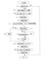
- 4 is a flowchart showing an electrical characteristic measurement program stored in a storage unit of a control device of the measuring device.
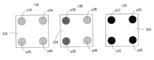
- 13A-13C are diagrams conceptually illustrating clamp states acquired by the measuring device.
- the mounting machine shown in FIG. 1 is for mounting components onto a circuit board, and includes a main body 2, a circuit board conveying and holding device 4, a component supplying device 6, a head moving device 8, and the like.
- the circuit board conveying and holding device 4 conveys and holds the circuit board P (hereinafter, abbreviated as board P).
- the conveying direction of the board P is the x direction
- the width direction of the board P is the y direction
- the thickness direction of the board P is the z direction.
- the y direction and the z direction are the front-rear direction and the up-down direction of the mounting machine, respectively. These x direction, y direction, and z direction are perpendicular to each other.
- the component supplying device 6 supplies electronic components (hereinafter, abbreviated as components) s to be mounted on the board P, and includes a plurality of tape feeders 14 and the like.
- the head moving device 8 holds the working head 16 and moves it in the x, y, and z directions.
- the working head 16 has a suction nozzle 18 that suctions and holds the components s.
- Reference numeral 20 denotes a camera.
- the camera 20 captures an image of the component s held by the suction nozzle 18, and based on the image captured by the camera 20, it is determined whether or not the component s is to be mounted on the circuit board P.
- Reference numeral 22 denotes a measuring device.
- the measuring device 22 measures the electrical characteristics of the component s as an object. Examples of electrical characteristics include L (inductance), C (capacitance), R (resistance), Z' (impedance), etc., and the measuring device 22 measures one or more of these.
- the measuring device 22 is fixedly mounted on the placement machine and is provided in the main body of the circuit board transport and holding device 4 via a storage section 26.
- a disposal passage 28 is provided between the storage section 26 and the measuring device 22, and the component s after its electrical characteristics have been measured is stored in the storage section 26 via the disposal passage 28.
- the measuring device 22 includes a main body 30, a mounting table 32 on which the component s is placed, a pair of probes 37 consisting of a stator 34 as a first probe and a mover 36 as a second probe, a mounting table moving device 40 that moves the mounting table 32, a mover moving device 41 that moves the mover 36 toward and away from the stator 34, an LCR measuring unit 42 (see Figure 7) that serves as an electrical characteristic measuring unit, and a clamping force detecting unit 58 that detects the clamping force of the pair of probes 37 on the component s.
- the component s has a functional unit r located in the center and a pair of electrode units p located on both sides of the functional unit r, as shown in Figure 6 and other figures.
- the component s can be clamped at the electrode units p on both sides by the stator 34 and the mover 36.
- the component s can be, for example, a square chip.
- the direction in which the pair of probes 37 approach and move away from each other is the y direction.
- the movement of the mover 36 in the direction in which it approaches the stator 34 is referred to as forward movement, and the movement of the mover 36 in the direction in which it moves away from the stator 34 is referred to as backward movement.
- forward movement the movement of the mover 36 in the direction in which it moves away from the stator 34 is referred to as backward movement.
- backward movement The same applies to the movement of the mounting table 32.
- the main body 30 is provided with a through hole 31 (see FIG. 4) that can communicate with the waste passage 28 .
- the mounting table 32 includes a component mounting portion 44 and a mounting portion holder 46 that holds the component mounting portion 44.
- a V-shaped groove 44c is formed in the component mounting portion 44, and a component s is placed on the V-shaped groove 44c.
- stator 34 and the mover 36 have opposing surfaces 34f and 36f, respectively, which face each other, and the part s is clamped at a pair of electrode portions p by the pair of opposing surfaces 34f and 36f.
- the stator 34 is held by a stator holder 55, which is fixed to the main body 30.
- the mover 36 is held integrally and movably by the mover holder 56, which is provided so as to be movable in the y direction relative to the main body 30. This allows the mover 36 to move towards and away from the stator 34.
- the stator 34 and the mover 36 are each connected to the LCR measurement unit 42 via a cable.
- the clamping force detection unit 58 includes a pressure sensor 58 provided on the stator 34.
- the pressure sensor 58 is, for example, a planar sensor in which a large number of pressure detection sensor elements are arranged in a plane, and each sensor element outputs an electrical signal according to the applied pressure.
- the pressure sensor 58 detects the distribution of pressure applied to the opposing surface 34f, in other words, the position of the part where the clamping force applied to the part s by the pair of probes 37 is large, the extent of the part where the clamping force is large, etc.
- the pressure sensor 58 can obtain whether the part s is in a proper clamped state (sometimes called a proper clamped state) by the pair of probes 37.
- the "proper clamped state” is a state in which the part s is clamped at the pair of electrodes p with a pressure equal to or greater than a set value without tilting.
- the pressure sensor 58 is located on an axis Ls extending in the direction in which the pair of probes 37 approach and separate from each other.
- the surface of the pressure sensor 58 is covered by a thin conductive film 59, which is a conductive sheet.
- the thin conductive film 59 covers the surface of the pressure sensor 58 and is in contact with the stator 34. Even if the part s is clamped by the pressure sensor 58 and the mover 36, it is difficult to measure the electrical characteristics of the part s. Therefore, the thin conductive film 59 is provided in a state where it covers the surface of the pressure sensor 58. Then, the electrical characteristics of the part s are measured by clamping the part s by the thin conductive film 59 and the mover 36.
- the surface 59f of the thin conductive film 59 can be considered to be the opposing surface 34f of the stator 34 facing the mover 36.
- the mounting table moving device 40 and the movable member moving device 41 each include air cylinders 60, 62 as a driving source, a pair of guide rails 64, 66 provided on the main body 30 as shown in FIGS. 3 and 4, a pair of mounting table sliders 68, 69 and movable member sliders 70, 71 movably engaged with the guide rails 64, 66, solenoid valve devices 74, 76, etc.
- the pair of guide rails 64, 66 are fixed to the main body 30, spaced apart in the x direction and extending in the y direction (the direction in which the stator 34 and the mover 36 approach and separate).
- the mounting section holder 46 is fixed to the pair of mounting platform sliders 68, 69, and the mover holder 56 is fixed to the pair of mover sliders 70, 71.
- the piston rod 60r of the air cylinder 60 is attached to the mounting section holder 46, and the piston rod 62r of the air cylinder 62 is attached to the mover holder 56.
- the air cylinders 60, 62 are installed with the piston rods 60r, 62r extending in the y direction.
- an air passage 80 is formed in the stator side member (for example, one or more of the upper part of the stator 34, the stator holder 55, and the main body 30) and is connected to the air cylinders 60, 62.
- An opening 80a of the air passage 80 is formed facing the opposing surface 36f of the mover 36.
- An ionizer 86 (see FIG. 5) is also connected to the air passage 80. The ionizer 86 ionizes the air by generating a corona discharge.
- an electromagnetic valve device 74 is provided between the two air chambers 60a, 60b of the air cylinder 60, the air source 90, the air passage 80, and the filter (atmosphere). The movement of the mounting portion holder 46 (mounting platform 32) and other operations are controlled by controlling the electromagnetic valve device 74.
- the air chambers 62a and 62b of the air cylinder 62 are connected to an air source 90, an air passage 80, and a filter (atmosphere) via an electromagnetic valve device 76.
- the movement of the movable member holder 56 (movable member 36) is controlled by controlling the electromagnetic valve device 76.
- a stopper 94 is provided on the portion of the mounting table 32 facing the movable member holder 56.
- the stopper 94 defines the limit of approach between the movable member holder 56 and the mounting table 32.
- a stopper 96 is provided on the stator holder 55. The stopper 96 defines the limit of approach between the stator 34 and the mounting table 32.
- the placement machine includes a control device 200.
- the control device 200 includes a controller 202, which is mainly a computer, and a plurality of drive circuits 204.
- the controller 202 includes an execution unit 210, a storage unit 212, an input/output unit 214, etc.
- the circuit board transport/holding device 4, the component supplying device 6, and the head moving device 8 are each connected to the input/output unit 214 via the drive circuits 204, and the solenoid valve devices 74, 76 of the mounting table moving device 40 and the movable element moving device 41 are also connected.
- the camera 20, the LCR measuring unit 42, the display 216, the pressure sensor 58, etc. are connected.
- the electrical characteristics of component s are measured by executing an electrical characteristics measurement program represented by the flowchart in FIG. 8.
- the solenoid valve devices 74, 76 are controlled based on the positions of the mounting table 32, the movable element 36, etc.
- the measurement results of the electrical characteristics, whether the clamping state is appropriate, etc. can be displayed on the display 216.
- the measuring device 22 is always in the initial state.
- the mover 36 is at the retracted end position, and the mounting table 32 is at the advanced end position, i.e., at the position where it abuts against the stopper 96.
- step 1 it is determined whether or not a command to measure the electrical characteristics of the component s has been issued. If the determination is YES, in S2, the component s is picked up by the suction nozzle 18 from the component supply device 6 and placed in the V-groove 44c.
- the mover 36 is advanced, and the component s is clamped between the mover 36 and the stator 34 (conductive thin film 59).
- the mounting table 32 is retracted to a position away from the component s and the pair of probes 37.
- the pressure sensor 58 detects the pressure distribution, and the clamping state of the part s by the pair of probes 37 is acquired. Then, in S6, it is determined whether the genuine part s is in the correct clamping state.
- FIG. 9 shows an example of the pressure distribution detected by the pressure sensor 58.
- a portion p where the pressure is high is a portion where the component s abuts against the pressure sensor 58, or a portion where the mover 36 abuts against the pressure sensor 58.
- 9A the part pA with high pressure is located almost in the center in the width direction (the width direction of the V-groove 44c), and its area almost corresponds to the area A (see FIG. 6) of the electrode part p of the regular component s.
- the pressure of the part pA is higher than the set value. Therefore, it is determined that the regular component s is in a properly clamped state by the pair of probes 37.
- the area pB where the pressure is high is located almost in the center in the width direction, but its size is different from the area A of the electrode part p of the regular part s. In this case, it is determined that the regular part s has been clamped in a rolled-over position by the pair of probes 37, or that a part other than the regular part s has been clamped, and it is determined that the clamping state is not correct.
- the part pC where the pressure is high is located off to one side from the center in the width direction. There are also cases where the pressure at part pC is lower than the set value. In this case, it is determined that part s has been clamped at an angle, that part s has been clamped out of alignment, and it is determined that the part is not in an appropriate clamped state.
- the area of part p where the pressure is high is a size that corresponds to the opposing surface 36f. In this case, it is determined that part s is not clamped (is not in an appropriate clamped state).
- the relative positional relationship between the stator 34 and the mover 36 can be obtained based on the spread of the high pressure part p.
- the presence or absence of assembly errors of the stator 34, the mover 36, etc. in the measuring device 22 can be obtained.
- the high pressure part hp is not present in the center, the centers of the stator 34 and the mover 36 may be misaligned, and based on this, it becomes possible to adjust the assembly of the measuring device 22, etc.
- the discharge time is awaited from when the component s was placed on the V-groove 44c in S7.
- the discharge time is the time during which the static electricity charged to the component s can be removed.
- the electrical characteristics of the component s are measured in S8. After the measurement of the electrical characteristics of the component s is completed, the movable member 36 is retracted and the mounting table 32 is retracted in S9 and 10. The component s that was clamped by the movable member 36 and the stator 34 is released and falls, and is accommodated in the accommodation section 26 via the through hole 31 and the disposal passage 28.
- the electrical characteristics of the component s are measured by one clamping operation of the component s by the pair of probes 37, and the pressure distribution is detected by the pressure sensor 58. Therefore, based on the detected pressure distribution, it is possible to directly obtain whether or not a genuine component s is in a proper clamping state. Furthermore, since the electrical characteristics are measured when a genuine component s is in a proper clamping state, the value of the electrical characteristics of the component s can be obtained with high accuracy.
- the clamp state acquisition unit is made up of the part of the control device 200 that stores S5, the part that executes it, etc.
- the electrical characteristics are measured when it is determined that the clamp state is appropriate, but this is not limiting. For example, after the electrical characteristics are measured, it is possible to obtain whether the clamp state of component s is appropriate or not, and obtain that the value of the electrical characteristics measured in the appropriate clamp state is the value of the electrical characteristics of component s. The value of the electrical characteristics measured when the clamp state is not appropriate is not adopted and is ignored.
- a pair of probes 237 includes a first probe 234 and a second probe (movable probe) 36 that are movable, and the main body 230 includes a rear wall portion 302 located on the rear side of the first probe 234.
- the measuring device 222 also includes a first probe moving device 304 (see Figure 11) that moves the first probe 234.
- the first probe 234 is held integrally and movably by the first probe holder 255. Note that in Figures 10-12, elements similar to those in the first embodiment are given the same reference numerals and will not be described.
- the first probe moving device 304 includes an air cylinder 310 as a drive source, guide rails 64, 66, first probe sliders 312, 314 (not shown), an electromagnetic valve device 316, an air source 90, etc.
- the guide rails 64, 66 are provided with stoppers 306 that define the movement limit of the first probe holder 255.
- the first measuring probe holder 255 is connected to the piston rod 310r of the air cylinder 310.
- the solenoid valve device 316 can be switched between a first position and a second position. In the first position, air from the air source 90 is supplied to the air chamber 310a of the air cylinder 310, thereby moving the first measuring probe holder 255 to an initial position where it abuts against the stopper 306. In the second position, the air chambers 310a and 310b of the air cylinder 310 are connected to each other, allowing the first measuring probe holder 255 to move freely.
- the first probe holder 255 When the first probe 234 is in its initial position, the first probe holder 255 is spaced apart from the rear wall 302. There is a gap between the rear wall 302 and the first probe 234, and the clamping force detection unit 320 is provided between the rear wall 302 and the first probe 234.
- the rear wall 302 can be made of an insulating material.
- the clamping force detection unit 320 includes a plurality of protrusions 322 provided on the opposing surface 255f of one of the rear wall 302 and the first probe holder 255 (e.g., the first probe holder 255), and a pressure sensor (which can be called a pressure-sensitive sheet) 324, which is a planar sensor provided on the opposing surface 302f of the other (e.g., the rear wall 302).
- the clamping force detection unit 320 is provided around the axis Ls extending in the direction in which the first probe 234 and the second probe 36 approach and separate.
- the pressure-sensitive sheet 324 is provided around the axis Ls and includes a portion facing the plurality of protrusions 322.
- the four protrusions 322 are equidistant from the axis Ls, and are provided two above and two below, and two to the left and right. In this embodiment, the four protrusions 322 are located at the four corners of the pressure-sensitive sheet 324.
- the electrical characteristics of the component s are measured by executing an electrical characteristics measurement program represented by the flow chart of FIG. Steps that are executed in the same manner in the flowchart of FIG. 12 and the flowchart of FIG. 8 are given the same step numbers and their explanations are omitted.
- the first probe holder 255 is in the initial position, and the mounting table 32 is in a position where it abuts against the stopper 96 of the first probe holder 255.
- the solenoid valve device 316 is switched from the first position to the second position, so that the first probe 234 is made freely movable (free).
- the mover 36 advances toward the first probe 234 and clamps the component s together with the first probe 234.
- the first probe 234 advances together with the mover 36 and collides with the rear wall section 302.
- the pressure sensor 324 detects the pressures (which can be considered as one aspect of pressure distribution) of the high-pressure portions p1 to p4, and in S22, it is obtained whether the component s is in a state where it is properly clamped by the pair of probes 237.
- the high pressure portions p1 to p4 are the portions with which the protrusions 322 of the pressure-sensitive sheet 324 come into contact.
- the pressures of the four portions p1A to p4A are greater than a first set value, which is a set value, and are equal to or less than a second set value that is greater than the first set value, and the pressures of the portions p1A to p4A are approximately the same.
- a first set value which is a set value
- a second set value that is greater than the first set value
- the pressures of the portions p1A to p4A are approximately the same.
- the pressure of two adjacent parts (e.g., parts p1B and p2B) of the four parts p1B to p4B is greater than the pressure of the remaining two (e.g., parts p3B and p4B).
- the pressure of parts p3B and p4B may also be lower than the first set value. In this case, it is determined that the part s is clamped unevenly and is not in an appropriate clamped state.
- 13C the pressure in the four portions p1C to p4C is higher than the second set value. In this case, it is estimated that the part s is not clamped by the pair of probes 237, and it is acquired that the part s is not in an appropriate clamped state.
- the pressure distribution that is determined to be in an appropriate clamping state may differ depending on the size of part s, etc.
- the electrical characteristics of the part s are measured in S8. Then, in S23, the first probe holder 255 is moved to the initial position by the control of the solenoid valve device 316, and is returned to the initial state.
- the first gauge head moving device 304 is not essential, and the first gauge head holder 255 may be manually moved to the initial position by an operator. In this case, the first gauge head 234 is always in a free state.
- the clamping force detection unit 320 can be provided in a portion including an axis Ls' extending parallel to the axis Ls.
- the clamping force detection unit 320 can be provided between the first probe holder 255 and the rear wall 302.
- protrusions 322 can be provided. Increasing the number of protrusions 322 allows the clamping state to be obtained in more detail.
- a pair of probes that can approach and move away from each other; an electrical characteristic measuring unit in which the pair of probes clamp an object and measure an electrical characteristic of the object; a clamping force detection unit that detects a clamping force applied to the object by the pair of probes.
- the clamping force detection unit detects the clamping force applied to an object by a pair of probes when the object is clamped by the pair of probes to measure electrical characteristics.
- the clamping force detection unit may include a pressure sensor.
- clamping force detection unit includes a pressure sensor that is a planar sensor equipped with multiple sensor elements.
- a pressure sensor In a pressure sensor, multiple sensor elements are arranged in a plane. The pressure sensor detects the pressure distribution within the plane. Based on the pressure distribution, the position and spread of the part with the strongest clamping force can be obtained, and a pair of probes can determine whether the correct part is properly clamped.
- a measuring device in which the clamping force detection unit is provided in a portion including an axis extending parallel to the direction in which the pair of measuring probes approach and separate.
- the clamping force detection unit may be provided on an axis that passes through the pair of opposing surfaces of the pair of probes and extends in the direction in which the pair of probes approach and separate, or it may be provided on an axis that does not pass through the pair of opposing surfaces but extends in the direction in which the pair of probes approach and separate.
- the pair of probes each include an opposing surface facing each other,
- the measuring device according to any one of claims (1) to (3), wherein the clamping force detection unit includes a pressure sensor provided on the opposing surface of at least one of the pair of measuring elements.
- the pressure sensor be a flat sensor.
- the pressure sensor is a planar sensor having a plurality of sensor elements, The measuring device according to claim 4, wherein the at least one probe includes a conductive sheet covering the planar sensor.
- the surface of the conductive sheet forms part of the surface facing the probe.
- the conductive sheet can be considered to be the probe.
- a cable can be connected directly to the conductive sheet, or the conductive sheet can be brought into contact with the probe and the cable can be connected to the probe.
- the pair of probes is a movable first probe and a second probe
- the measuring device includes a main body having a rear wall portion provided on a rear side of the first probe, the first probe is located at a position spaced apart from the rear wall portion in an initial state,
- the measuring device according to any one of (1) to (3), wherein the clamping force detection unit is provided between the first probe and the rear wall portion.
- clamping force detection unit includes one or more protrusions provided on either the first measuring element or the rear wall, and one or more pressure sensors provided on the other of the first measuring element and the rear wall, facing the one or more protrusions.
- the one or more pressure sensors can be a single planar sensor that includes a portion facing one or more protrusions, or can be provided in correspondence with each of the one or more protrusions.
- the clamping force detection unit includes a pressure sensor that is a planar sensor having a plurality of sensor elements, The measuring device according to any one of items (1) to (7), further comprising a clamping state acquisition unit that acquires a clamping state of the object by the pair of measuring probes based on a pressure distribution detected by the pressure sensor.
- the clamping state acquisition unit acquires information on whether a clamping state of the object by the pair of probes is appropriate or not
- the measuring device described in item (8) is configured to, when the clamped state of the object by the pair of probes acquired by the clamped state acquisition unit is in an appropriate state, acquire the electrical characteristics measured by the electrical characteristic measuring unit in the clamped state as the electrical characteristics of the object.
- the electrical characteristics may be measured in that clamp state, or after the electrical characteristics are measured, it may be determined whether the clamp state is appropriate, and if the clamp state is appropriate, the electrical characteristics may be acquired.
- the clamp state acquisition unit may also be capable of acquiring whether the part clamped by the pair of probes is a genuine part.
- the clamping state acquisition unit acquires information on whether a clamping state of the object by the pair of probes is appropriate or not,
- the measuring device according to claim 8, wherein the electrical characteristic measuring unit measures the electrical characteristics of the object in a clamped state acquired by the clamp state acquisition unit using the pair of probes when the clamped state of the object acquired by the clamp state acquisition unit is in an appropriate state.
- the clamping force detection unit includes a pressure sensor having a plurality of sensor elements, The measuring device according to any one of claims (8) to (10), wherein the clamping state acquisition unit acquires whether the object is properly clamped by the pair of measuring probes based on the spread of the area where the pressure detected by the pressure sensor is equal to or greater than a set value.
- a measuring device including a pair of probes that can approach and move away from each other, the pair of probes clamping an object to measure an electrical characteristic of the object, a clamping force detection unit that detects a clamping force of the pair of probes on the object when the object is clamped by the pair of probes and the electrical characteristics are measured.
- the measuring device described in this section may employ any one of the technical features described in sections (1) through (11).
- a measuring device including a pair of probes that can approach and move away from each other, the pair of probes clamping an object to measure an electrical characteristic of the object, A measuring device capable of detecting a clamping force applied to the object by the pair of probes when the pair of probes clamp the object, and measuring electrical characteristics of the object.
- the measuring device described in this section may employ any one of the technical features described in sections (1) through (12).
- a relative positional relationship acquisition device for acquiring a relative positional relationship between a pair of clamp members that can approach and separate from each other, comprising: A relative position relationship acquisition device that includes a pressure sensor having a plurality of sensor elements and is arranged on an axis parallel to the approaching/separating direction of the pair of clamp members, and acquires the relative position relationship of the pair of clamp members based on the pressure distribution detected by the pressure sensor when the pair of clamp members approach each other.
- the relative positional relationship acquisition device described in this section can employ any one of the technical features described in sections (1) to (13).
- the pair of clamping members corresponds to the pair of measuring probes.
- the relative positional relationship acquisition device can correspond to the control device. Based on the relative positional relationship between the pair of clamping members, it becomes possible to acquire and correct assembly errors, etc., between the pair of clamping members, thereby improving the assembly accuracy of the pair of clamping members.
Landscapes
- Physics & Mathematics (AREA)
- General Physics & Mathematics (AREA)
- Engineering & Computer Science (AREA)
- General Engineering & Computer Science (AREA)
- Testing Of Short-Circuits, Discontinuities, Leakage, Or Incorrect Line Connections (AREA)
Priority Applications (2)
| Application Number | Priority Date | Filing Date | Title |
|---|---|---|---|
| PCT/JP2023/017524 WO2024232034A1 (ja) | 2023-05-10 | 2023-05-10 | 測定装置 |
| JP2025519243A JPWO2024232034A1 (https=) | 2023-05-10 | 2023-05-10 |
Applications Claiming Priority (1)
| Application Number | Priority Date | Filing Date | Title |
|---|---|---|---|
| PCT/JP2023/017524 WO2024232034A1 (ja) | 2023-05-10 | 2023-05-10 | 測定装置 |
Publications (1)
| Publication Number | Publication Date |
|---|---|
| WO2024232034A1 true WO2024232034A1 (ja) | 2024-11-14 |
Family
ID=93431497
Family Applications (1)
| Application Number | Title | Priority Date | Filing Date |
|---|---|---|---|
| PCT/JP2023/017524 Ceased WO2024232034A1 (ja) | 2023-05-10 | 2023-05-10 | 測定装置 |
Country Status (2)
| Country | Link |
|---|---|
| JP (1) | JPWO2024232034A1 (https=) |
| WO (1) | WO2024232034A1 (https=) |
Cited By (1)
| Publication number | Priority date | Publication date | Assignee | Title |
|---|---|---|---|---|
| US20250052794A1 (en) * | 2021-12-21 | 2025-02-13 | Fuji Corporation | Electrical characteristic acquiring device |
Citations (8)
| Publication number | Priority date | Publication date | Assignee | Title |
|---|---|---|---|---|
| JPH03227544A (ja) * | 1990-02-01 | 1991-10-08 | Nippon Telegr & Teleph Corp <Ntt> | ウエハプローバ装置 |
| JPH11118877A (ja) * | 1997-10-14 | 1999-04-30 | Nec Corp | Ic試験装置 |
| JP2000199779A (ja) * | 1998-12-31 | 2000-07-18 | Daito:Kk | テストハンドの制御方法、記録媒体及び計測制御システム |
| JP2000266810A (ja) * | 1999-03-16 | 2000-09-29 | Fukuoka Nippon Denki Kk | Icハンドラ |
| JP2008224586A (ja) * | 2007-03-15 | 2008-09-25 | Yokogawa Electric Corp | 検査装置 |
| US20100206041A1 (en) * | 2009-02-19 | 2010-08-19 | Sungkyunkwan University Foundation Corporate Collaboration | Scratch testing apparatus for performing scratching test while gradually increasing or decreasing load |
| JP2019211407A (ja) * | 2018-06-08 | 2019-12-12 | 日置電機株式会社 | 移動装置、基板検査装置および制御方法 |
| WO2021074943A1 (ja) * | 2019-10-14 | 2021-04-22 | 株式会社Fuji | 測定装置、実装機、クランプ状態取得装置 |
-
2023
- 2023-05-10 JP JP2025519243A patent/JPWO2024232034A1/ja active Pending
- 2023-05-10 WO PCT/JP2023/017524 patent/WO2024232034A1/ja not_active Ceased
Patent Citations (8)
| Publication number | Priority date | Publication date | Assignee | Title |
|---|---|---|---|---|
| JPH03227544A (ja) * | 1990-02-01 | 1991-10-08 | Nippon Telegr & Teleph Corp <Ntt> | ウエハプローバ装置 |
| JPH11118877A (ja) * | 1997-10-14 | 1999-04-30 | Nec Corp | Ic試験装置 |
| JP2000199779A (ja) * | 1998-12-31 | 2000-07-18 | Daito:Kk | テストハンドの制御方法、記録媒体及び計測制御システム |
| JP2000266810A (ja) * | 1999-03-16 | 2000-09-29 | Fukuoka Nippon Denki Kk | Icハンドラ |
| JP2008224586A (ja) * | 2007-03-15 | 2008-09-25 | Yokogawa Electric Corp | 検査装置 |
| US20100206041A1 (en) * | 2009-02-19 | 2010-08-19 | Sungkyunkwan University Foundation Corporate Collaboration | Scratch testing apparatus for performing scratching test while gradually increasing or decreasing load |
| JP2019211407A (ja) * | 2018-06-08 | 2019-12-12 | 日置電機株式会社 | 移動装置、基板検査装置および制御方法 |
| WO2021074943A1 (ja) * | 2019-10-14 | 2021-04-22 | 株式会社Fuji | 測定装置、実装機、クランプ状態取得装置 |
Cited By (1)
| Publication number | Priority date | Publication date | Assignee | Title |
|---|---|---|---|---|
| US20250052794A1 (en) * | 2021-12-21 | 2025-02-13 | Fuji Corporation | Electrical characteristic acquiring device |
Also Published As
| Publication number | Publication date |
|---|---|
| JPWO2024232034A1 (https=) | 2024-11-14 |
Similar Documents
| Publication | Publication Date | Title |
|---|---|---|
| TW201712346A (zh) | 用於測試電路板之平行測試器的定位裝置及用於測試電路板的平行測試器 | |
| US11491532B2 (en) | Device and method for removing a workpiece part from the rest of the workpiece | |
| CN1977577B (zh) | 印刷基板支撑设备 | |
| JP6684795B2 (ja) | 検査装置 | |
| WO2024232034A1 (ja) | 測定装置 | |
| JP2011106852A (ja) | 電子部品検査装置 | |
| CN110383091A (zh) | 测试装置与用于测试电路板的方法 | |
| CN109108404B (zh) | 一种电火花加工装置、系统及方法 | |
| CN107736086B (zh) | 检查装置 | |
| WO2021074943A1 (ja) | 測定装置、実装機、クランプ状態取得装置 | |
| JP7326277B2 (ja) | 測定装置 | |
| CN106358438B (zh) | 检查装置 | |
| US20250052794A1 (en) | Electrical characteristic acquiring device | |
| CN210678331U (zh) | 一种基于多传感器组合的铸件种类识别装置 | |
| US12584952B2 (en) | Measuring device | |
| JP7013511B2 (ja) | 装着機 | |
| JP6852127B2 (ja) | 検査装置および検査方法 | |
| JP7167265B2 (ja) | 検査装置 | |
| JP7155445B2 (ja) | 装着機 | |
| CN211121144U (zh) | 电路板局部厚度检测设备 | |
| US12535502B2 (en) | Measuring device | |
| JP7013617B2 (ja) | 装着機 | |
| JP7504134B2 (ja) | 実装機 | |
| JP2026023630A (ja) | 電気的特性取得装置 | |
| JP6908676B2 (ja) | 電気的特性取得方法および部品装着方法 |
Legal Events
| Date | Code | Title | Description |
|---|---|---|---|
| 121 | Ep: the epo has been informed by wipo that ep was designated in this application |
Ref document number: 23936587 Country of ref document: EP Kind code of ref document: A1 |
|
| ENP | Entry into the national phase |
Ref document number: 2025519243 Country of ref document: JP Kind code of ref document: A |
|
| WWE | Wipo information: entry into national phase |
Ref document number: 2025519243 Country of ref document: JP |
|
| NENP | Non-entry into the national phase |
Ref country code: DE |