WO2024232004A1 - ワーク接続装置 - Google Patents
ワーク接続装置 Download PDFInfo
- Publication number
- WO2024232004A1 WO2024232004A1 PCT/JP2023/017396 JP2023017396W WO2024232004A1 WO 2024232004 A1 WO2024232004 A1 WO 2024232004A1 JP 2023017396 W JP2023017396 W JP 2023017396W WO 2024232004 A1 WO2024232004 A1 WO 2024232004A1
- Authority
- WO
- WIPO (PCT)
- Prior art keywords
- workpiece
- work
- pressing
- connection device
- holding
- Prior art date
- Legal status (The legal status is an assumption and is not a legal conclusion. Google has not performed a legal analysis and makes no representation as to the accuracy of the status listed.)
- Ceased
Links
Images













Classifications
-
- B—PERFORMING OPERATIONS; TRANSPORTING
- B23—MACHINE TOOLS; METAL-WORKING NOT OTHERWISE PROVIDED FOR
- B23K—SOLDERING OR UNSOLDERING; WELDING; CLADDING OR PLATING BY SOLDERING OR WELDING; CUTTING BY APPLYING HEAT LOCALLY, e.g. FLAME CUTTING; WORKING BY LASER BEAM
- B23K20/00—Non-electric welding by applying impact or other pressure, with or without the application of heat, e.g. cladding or plating
- B23K20/10—Non-electric welding by applying impact or other pressure, with or without the application of heat, e.g. cladding or plating making use of vibrations, e.g. ultrasonic welding
-
- B—PERFORMING OPERATIONS; TRANSPORTING
- B23—MACHINE TOOLS; METAL-WORKING NOT OTHERWISE PROVIDED FOR
- B23K—SOLDERING OR UNSOLDERING; WELDING; CLADDING OR PLATING BY SOLDERING OR WELDING; CUTTING BY APPLYING HEAT LOCALLY, e.g. FLAME CUTTING; WORKING BY LASER BEAM
- B23K26/00—Working by laser beam, e.g. welding, cutting or boring
- B23K26/08—Devices involving relative movement between laser beam and workpiece
- B23K26/0869—Devices involving movement of the laser head in at least one axial direction
- B23K26/0876—Devices involving movement of the laser head in at least one axial direction in at least two axial directions
- B23K26/0884—Devices involving movement of the laser head in at least one axial direction in at least two axial directions in at least three axial directions, e.g. manipulators, robots
-
- B—PERFORMING OPERATIONS; TRANSPORTING
- B23—MACHINE TOOLS; METAL-WORKING NOT OTHERWISE PROVIDED FOR
- B23K—SOLDERING OR UNSOLDERING; WELDING; CLADDING OR PLATING BY SOLDERING OR WELDING; CUTTING BY APPLYING HEAT LOCALLY, e.g. FLAME CUTTING; WORKING BY LASER BEAM
- B23K37/00—Auxiliary devices or processes, not specially adapted for a procedure covered by only one of the other main groups of this subclass
- B23K37/02—Carriages for supporting the welding or cutting element
- B23K37/0211—Carriages for supporting the welding or cutting element travelling on a guide member, e.g. rail, track
-
- B—PERFORMING OPERATIONS; TRANSPORTING
- B23—MACHINE TOOLS; METAL-WORKING NOT OTHERWISE PROVIDED FOR
- B23K—SOLDERING OR UNSOLDERING; WELDING; CLADDING OR PLATING BY SOLDERING OR WELDING; CUTTING BY APPLYING HEAT LOCALLY, e.g. FLAME CUTTING; WORKING BY LASER BEAM
- B23K37/00—Auxiliary devices or processes, not specially adapted for a procedure covered by only one of the other main groups of this subclass
- B23K37/04—Auxiliary devices or processes, not specially adapted for a procedure covered by only one of the other main groups of this subclass for holding or positioning work
- B23K37/0408—Auxiliary devices or processes, not specially adapted for a procedure covered by only one of the other main groups of this subclass for holding or positioning work for planar work
Definitions
- the present invention relates to a work connection device for connecting multiple workpieces.
- Patent Document 1 describes a laser processing device 1 that laser welds a part P to a workpiece W placed on a workbench 4 (see paragraphs "0030" to "0032" and Figure 1, etc.).
- the laser processing device 1 described in Patent Document 1 uses a pressing portion 26 to press the top surface of a workpiece W and the top surface of a part P placed on a worktable 4, and in this state, irradiates laser light L from a laser processing head 5 to connect the workpiece W and the part P (see paragraphs "0054" to "0057” and Figure 10, etc.).
- the laser processing device 1 (hereinafter referred to as the "workpiece connecting device") does not cause any problems in connection when the workpiece W is planar and the work table 4 is also planar, but when the workpiece W has a complex shape such as a curved or bent shape, it is very difficult to connect the part P to any point on the workpiece W having a complex shape.
- the present invention has been made in response to the above-mentioned problems with the conventional technology, and aims to provide a work connection device that can quickly connect components to a workpiece, even if the workpiece has a complex shape, and further, a work connection device that improves the appearance quality of the workpiece after connection.
- the first aspect of the present invention is a work connection device that biases a second work against a surface of a first work to connect the second work to the surface of the first work, the work connection device being characterized by comprising an articulated robot and a support body that is connected to the tip of the articulated robot and can abut against the back surface of the first work.
- the second aspect of the present invention is characterized in that in the work connection device of the first aspect, the support body is provided with a plurality of first plates arranged so that their normals are directed in a plurality of directions.
- the third aspect of the present invention is characterized in that in the workpiece connecting device of the second aspect, a polyhedron is connected to the tip of the articulated robot, and each of the multiple first plates is separately connected to one of the faces that constitute the polyhedron.
- the fourth aspect of the present invention is characterized in that in the work connection device of the third aspect, the polyhedron has an open surface and an internal cavity, and each of the plurality of first plates is clamped to the polyhedron by a fastener from the cavity and is separately connected to one of the surfaces that constitute the polyhedron.
- the fifth aspect of the present invention is characterized in that in the work connection device of any of the second to fourth aspects, the first plate has a structure in which the center portion protrudes.
- a sixth aspect of the present invention is a work connection device that urges a second work against a surface of a first work to connect the second work to the surface of the first work, comprising a moving body and at least one second plate that is arranged on the moving body and can abut against the back surface of the first work and has a normal that can be changed to a plurality of directions, and is characterized in that the direction of the normal of at least one of the second plates can be fixed when the second plate abuts against the back surface of the first work.
- the seventh aspect of the present invention is characterized in that in the work connection device of the sixth aspect, the second plate has a structure in which the center portion protrudes.
- the support body is provided with a plurality of first plates arranged so that their normals point in a plurality of directions. Therefore, in addition to the effect of the work connection device of the first aspect, even if the first work has a complex shape, an appropriate first plate can be selected and abutted against the back surface of the first work, and thus the second work can be efficiently connected to the front surface of the first work. On the other hand, even if one first plate becomes unusable, the other first plate can be used, thereby improving the durability of the device.
- a polyhedron is connected to the tip of the articulated robot, and each of the multiple first plates is separately connected to one face that constitutes the polyhedron, so that in addition to the effect of the workpiece connecting device of the second aspect, it is possible to easily create a structure in which an appropriate first plate can be selected and abutted against a first workpiece of a complex shape.
- the polyhedron has an open surface and an internal cavity, and each of the multiple first plates is clamped to the polyhedron by fasteners from the cavity and is separately connected to one of the surfaces that make up the polyhedron.
- the first plate has a structure with a protruding center, so that in addition to the effect of the work connection device of any of the second to fourth aspects, it is possible to prevent distortion occurring on the surface of the first work and/or the surface of the second work, thereby improving the appearance quality.
- the second plate has a structure in which the center protrudes, so that in addition to the effect of the work connection device of the sixth aspect, it is possible to prevent distortion occurring on the surface of the first work and/or the surface of the second work, thereby improving the appearance quality.
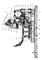
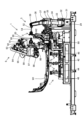
- FIG. 1 is an overall front view of a workpiece connecting device according to a first embodiment of the present invention
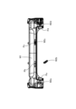
- FIG. 2 is a front view of a first workpiece according to the first embodiment.
- FIG. 2 is a plan view showing a first workpiece and a second workpiece of the first embodiment.
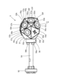
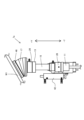
- FIG. 4 is a left side view of the first pressing portion of the first embodiment.
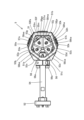
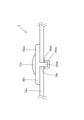
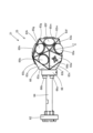
- FIG. 4 is a bottom view of the first pressing portion of the first embodiment. This is a cross-sectional view taken along line AA in FIG.
- FIG. 4 is a plan view of a second pressing portion and a third pressing portion of the first embodiment.
- FIG. 4 is a side view showing a state before the second pressing portion of the first embodiment is extended.
- FIG. 11 is a side view showing a state after the second pressing portion of the first embodiment is extended.
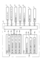
- FIG. FIG. 1 is a block diagram of a workpiece connecting device according to a first embodiment.
- FIG. 2 is a block diagram of a main controller of the work connection device of the first embodiment.
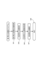
- 5 is a flowchart of a connection processing program in the work connection device of the first embodiment.
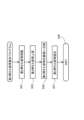
- 5 is a flowchart of a first holding part selection program in the workpiece connecting device of the first embodiment.
- 5 is a flowchart of a second pressing unit and other operation program in the workpiece connecting device of the first embodiment.
- FIG. 4 is a diagram showing a first stage state of a first pressing part in the workpiece connecting device of the first embodiment.
- FIG. 11 is a diagram showing a second stage state of the first pressing part in the workpiece connecting device of the first embodiment.
- FIG. 11 is a diagram showing a final stage state of the first pressing part in the workpiece connecting device of the first embodiment.
- FIG. 18 is an enlarged view of part B in FIG. 17 .
- 10 is a diagram showing a state in which the first pressing portion presses another portion of the first work in the work connecting device of the first embodiment.
- FIG. FIG. 4 is a diagram showing a first stage state of a second pressing part in the workpiece connecting device of the first embodiment.
- FIG. 11 is a view showing a second stage state of the second pressing part in the workpiece connecting device of the first embodiment.
- FIG. 11 is a diagram showing a final stage state of the second pressing part in the workpiece connecting device of the first embodiment.
- 1 is a side view showing a state in which the second pressing portion of the first embodiment abuts against a horizontal surface of the first workpiece.
- FIG. 1 is a side view showing a state in which the second pressing portion of the first embodiment abuts against an inclined surface of the first workpiece.
- FIG. 11 is a left side view of a first pressing portion of the second embodiment. This is a cross-sectional view taken along the line CC of Figure 25.
- FIG. 13 is a left side view of a first pressing portion of the third embodiment.
- FIG. 13 is a left side view of a first pressing portion of the fourth embodiment.
- FIG. 13 is a left side view of a first pressing portion of the fifth embodiment.
- FIG. 23 is a side view showing the second pressing portion of the sixth embodiment.
- Figure 1 is an overall front view of a work connection device in a first embodiment of the present invention
- Figure 2 is a front view of a first work in the first embodiment
- Figure 3 is a plan view showing the first work and the second work in the first embodiment.
- the work connection device 1 of this embodiment uses a multi-joint robot 9 for a welding machine, a first pressing multi-joint robot 3, and a second pressing and third pressing mechanism 7 to bias and connect a second work W2 to a first work W1 fixed on a mounting table 88 arranged in a housing H.
- one first pressing articulated robot 3 is placed on the right side of the first workpiece W1 in FIG. 1, but in reality, two first pressing articulated robots 3 are placed on both the left and right sides of the first workpiece W1.
- the placement position and number of the first pressing articulated robots 3 can be changed as appropriate depending on the shape of the first workpiece W1.
- the first work W1 is described as a car bumper as an example, with the second work W2a, W2b, W2c, and W2d connected to four connection positions Pa, Pb, Pc, and Pd of the first work W1, respectively.
- the shapes of the first work W1 and the second work W2, and the number and connection positions of the second work W2 are not limited to this and can be changed as appropriate.
- the work connection device 1 of this embodiment includes a mounting table 88 arranged in a housing H, a welding multi-joint robot 9, a first holding multi-joint robot 3, and second and third holding mechanisms 7 fixed to the mounting table 88, a control device 8 for controlling the entire work connection device 1, a robot controller 12 for controlling the welding multi-joint robot 9 and the first holding multi-joint robot 3, a compressor 4 that controls part of the operation of the second and third holding mechanisms 7, and an operation panel 2 arranged in the housing H and used by an operator of the device to command the operation of the work connection device 1.
- the articulated robot 9 for welding is a general six-axis articulated robot that operates according to commands from a robot controller 12, and uses an ultrasonic vibrator 20 (see Figure 10) connected to its tip to apply pressure to weld the second workpiece W2 to the first workpiece W1.
- the articulated welding robot 9 has six axes: a first rotation axis (not shown) for rotating the first base 89 relative to the mounting table 88, a second rotation axis 90 for rotating the lower arm 91 back and forth relative to the first base 89, a third rotation axis 92 for rotating the first middle arm 93 relative to the lower arm 91, a fourth rotation axis 94 for rotating the second middle arm 95 relative to the first middle arm 93, a fifth rotation axis 96 for rotating the upper arm 97 relative to the second middle arm 95, and a sixth rotation axis 98 for coaxially rotating the rotating part 99 relative to the upper arm 97.
- a first rotation axis (not shown) for rotating the first base 89 relative to the mounting table 88
- a second rotation axis 90 for rotating the lower arm 91 back and forth relative to the first base 89
- a third rotation axis 92 for rotating the first middle arm 93 relative to the lower arm 91
- An ultrasonic vibrator 20 is fixed to the tip of the rotating part 99 of the welding machine articulated robot 9. With the second workpiece W2 placed on the first workpiece W1, the ultrasonic vibrator 20 is brought into contact with the first workpiece W1 and the second workpiece W2, and the ultrasonic vibrator 20 is driven by a signal from the welding machine driver 14 (see FIG. 10) described later, thereby welding the second workpiece W2 to the first workpiece W1.
- the first pressing articulated robot 3 is a general five-axis articulated robot that operates according to commands from the robot controller 12, and the first pressing part 5 connected to the tip presses the back surface of the first workpiece W1 when the welding articulated robot 9 welds the second workpiece W2 to the first workpiece W1.
- the first pressing articulated robot 3 has five axes: a first rotation axis 31 for rotating the second base 32 relative to the first base 29, a second rotation axis 33 for rotating the lower arm 34 back and forth relative to the second base 32, a third rotation axis 35 for rotating the middle arm 36 back and forth relative to the lower arm 34, a fourth rotation axis 37 for rotating the upper arm 38 back and forth relative to the middle arm 36, and a fifth rotation axis 39 for rotating the first pressing part 5 relative to the upper arm 38.
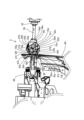
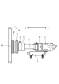
- Figure 4 is a left side view of the first pressing portion of this embodiment
- Figure 5 is a bottom view thereof
- Figure 6 is a cross-sectional view taken along line A-A in Figure 4.
- the first pressing unit 5 in this embodiment presses the back surface of the first workpiece W1 when the welding articulated robot 9 welds the second workpiece W2 to the first workpiece W1.
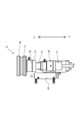
- the first holding part 5 in this embodiment is composed of a first mounting part 52 connected to the fifth rotation axis 39 of the first holding articulated robot 3, a long arm 54 having one end connected to the first mounting part 52, a second mounting part 56 connected to the other end of the arm 54 by five attachments 56a, 56b, 56c, 56d and 56e, and a support 51 connected to the second mounting part 56.
- the support 51 is a polyhedron consisting of 14 first plates 53a, 53b, 53c, 53d, 53e, 53f, 53g, 53h, 53j, 53k, 53m, 53x, 53y and 53z, each of which is a substantially triangular flat plate.
- first plates 53a, 53b, 53c, 53d, 53e, 53f, 53g, 53h, 53j, 53k, 53m, 53x, 53y and 53z On the surface of each of the first plates 53a, 53b, 53c, 53d, 53e, 53f, 53g, 53h, 53j, 53k, 53m, 53x, 53y and 53z, flat disks 55a (not shown), 55b, 55c, 55d (not shown), 55e, 55f, 55g, 55h, 55j (not shown), 55k and 55m of a predetermined thickness are fixed.
- the flat disks 55a (not shown), 55b, 55c, 55d (not shown), 55e, 55f, 55g, 55h, 55j (not shown), 55k and 55m have circular projections 57a (not shown), 57b, 57c, 57d (not shown), 57e, 57f, 57g, 57h, 57j (not shown), 57k and 57m, the central portions of which protrude into the outer periphery of the substantially triangular first plates.
- the first plates 53a and 53d are shown in a state before the disks 55a and 55d are attached, but in reality, the disks 55a and 55d are attached to the first plates 53a and 53d as well, just like the other first plates.
- the normals of the first plates 53a, 53b, 53c, 53d, 53e, 53f, 53g, 53h, 53j, 53k, 53m, 53x, 53y and 53z are arranged so that each of them faces in a different direction.
- the support 51 has an opening surface 51b formed by the housing 51a and a cavity 51c inside the polyhedron, and each of the disks 55a (not shown), 55b, 55c, 55d (not shown), 55e, 55f, 55g, 55h, 55j (not shown), 55k and 55m consists of a disk body 55aa, 55ba, 55ca, 55da, 55ea, 55fa, 55ga, 55ha, 55ja, 55ka and 55ma (all except 55ea are not shown) and a screw portion 55ab, 55bb, 55cb, 55db, 55eb, 55fb, 55gb, 55hb, 55jb, 55kb and 55mb (all except 55eb are not shown) extending from the disk body.
- each of the disks 55a (not shown), 55b, 55c, 55d (not shown), 55e, 55f, 55g, 55h, 55j (not shown), 55k and 55m is connected to the fasteners 58aa (not shown), 58ba, 58ca, 58da (not shown), 58ea, 58fa, 58ga, 58ha, 58ja, 58ka and 58ma from the cavity 51c and the washers 58ab, 58bb, 58cb, 58db, 58eb , 58fb, 58gb, 58hb, 58jb, 58kb, and 58mb (not shown except for 58eb) are individually sandwiched through holes 59a, 59b, 59c, 59d, 59e, 59f, 59g, 59h, 59j, 59kb, and 59m (not shown except for 59a, 59d, and 59e)
- Figure 7 is a plan view of the second and third holding parts of the first embodiment
- Figure 8 is a side view showing the state of the second holding part before it is extended
- Figure 9 is a side view showing the state of the second holding part after it is extended.
- the second pressing unit 7a and the third pressing unit 7b are provided below the first workpiece W1.
- the positions and number of the second and third pressing units 7a and 7b of the second and third pressing mechanisms 7, which will be described later, can be changed as appropriate depending on the shape of the first workpiece W1.
- the second and third pressing mechanisms 7 of this embodiment are provided with a second pressing part 7a on the right side of Figure 1 and a third pressing part 7b on the left side of Figure 1 along the longitudinal direction of the first workpiece W1 below the first workpiece W1.
- the second pressing portion 7a includes a first base 11, an extendable rod 15 that extends and retracts relative to the first base 11, a compression spring (not shown) disposed inside the extendable rod 15 and biasing the extendable rod 15 upward, a second pressing cylinder 42 that extends and retracts the extendable rod 15 relative to the first base 11, a second vertical fixing solenoid valve 28 disposed on the top of the first base 11 for fixing the vertical position of the extendable rod 15, a second base 13 fixed to the top end of the extendable rod 15, a swivel fixing solenoid valve 26 disposed on the top of the second base 13 for fixing the swivel of a second pressing suction portion 46 described below, a telescopic portion 17 disposed on the top of the swivel fixing solenoid valve 26 and capable of extending and retracting, and a second pressing suction portion 46 (corresponding to the "second plate" of the present invention) disposed on the top of the telescopic portion 17.
- the second holding portion 7a configured as described above first lowers the second base portion 13, the second swivel fixing solenoid valve 26, the expansion/contraction portion 17, and the second holding suction portion 46 in the -Y direction using the second holding cylinder 42, and then fixes the expansion rod 15 in the lowered position with the compression spring compressed using the second up/down fixing solenoid valve 28.
- the second swivel fixing solenoid valve 26 may fix the telescopic section 17 and the second holding suction section 46, but considering the subsequent process, it is better not to fix the telescopic section 17 and the second holding suction section 46, but to leave them free to swivel.
- Figure 8 illustrates the second base 13, the second swivel fixing solenoid valve 26, the extension/retraction section 17, and the second holding suction section 46 in the lowered state.
- Figure 9 illustrates the second base 13, the second swivel fixing solenoid valve 26, the extension section 17, and the second holding suction section 46 in the raised state.
- the second pressing portion 7a is configured to be movable in the +X direction or the -X direction on the right mounting table 88b fixed to the mounting table 88 by using a second pressing slide motor 22 arranged near the right mounting table 88b and a ball screw arranged inside the right mounting table 88b.
- the rotational force of a motor gear fixed to the motor shaft of the second pressing slide motor 22 is transmitted to the ball screw.
- the third holding portion 7b has the same structure as the second holding portion 7a, except for the third holding cylinder 44 that extends and retracts the telescopic rod relative to the first base, and the third holding suction portion 48 (corresponding to the "second plate" of the present invention) that is located above the telescopic portion.
- the third holding cylinder 44 lowers the second base (not shown), the third swivel fixing solenoid valve 30, the expansion section (not shown) and the third holding suction section 48 in the -Y direction, and then the third up-down fixing solenoid valve 40 fixes the expansion rod in the lowered position with the compression spring compressed.
- the third swivel fixing solenoid valve 30 may fix the telescopic section and the third holding suction section 48, but considering the subsequent process, it is better not to fix the telescopic section and the third holding suction section 48, but to leave them free to swivel.
- the third pressing portion 7b is configured to be movable in the +X direction or the -X direction on the left mounting table 88a fixed to the mounting table 88 by using a third pressing slide motor 24 arranged near the left mounting table 88a and a ball screw arranged inside the left mounting table 88a.
- the rotational force of a motor gear fixed to the motor shaft of the third pressing slide motor 24 is transmitted to the ball screw.
- Figure 10 is a block diagram of the work connection device of this embodiment
- Figure 11 is a block diagram of the main controller of the work connection device of this embodiment.
- the work connection device 1 includes a main controller 10 electrically connected to a power source 6, an air compressor 4 electrically connected to the main controller 10 for driving the second pressing cylinder 42, the third pressing cylinder 44, the second pressing suction unit 46, and the third pressing suction unit 48, a robot controller 12 electrically connected to the main controller 10 for controlling the welding machine multi-joint robot 9 and the first pressing multi-joint robot 3, a welding machine driver 14 for driving the ultrasonic vibrator 20, a motor driver 16 for driving the second pressing slide motor 22 and the third pressing slide motor 24, a solenoid valve driver 18 for driving the second swivel fixing solenoid valve 26, the second up-down fixing solenoid valve 28, the third swivel fixing solenoid valve 30, and the third up-down fixing solenoid valve 40, and an operation panel 2 for receiving input from an operator of the device.
- a main controller 10 electrically connected to a power source 6
- an air compressor 4 electrically connected to the main controller 10 for driving the second pressing cylinder 42, the third pressing
- the main controller 10, welder driver 14, motor driver 16 and solenoid valve driver 18 are housed within the control device 8.
- the main controller 10 includes a CPU (Central Processing Unit) 38, a RAM (Random Access Memory) 50 connected to the CPU 38 for input/output, and a ROM (Read Only Memory) 60 connected to the CPU 38 for input/output.
- a CPU Central Processing Unit
- RAM Random Access Memory
- ROM Read Only Memory
- the RAM 50 includes a connection processing procedure data table 50a that stores the connection positions for connecting the second workpiece W2 to the first workpiece W1, the tilt information (tilt direction and tilt angle) at the connection positions, and the connection order, a first pressing current state data table 50b that stores the current state of the first pressing section 5, a second pressing current state data table 50c that stores the current state of the second pressing section 7a, and a third pressing current state data table 50d that stores the current state of the third pressing section 7b.
- a connection processing procedure data table 50a that stores the connection positions for connecting the second workpiece W2 to the first workpiece W1, the tilt information (tilt direction and tilt angle) at the connection positions, and the connection order
- a first pressing current state data table 50b that stores the current state of the first pressing section 5
- a second pressing current state data table 50c that stores the current state of the second pressing section 7a
- a third pressing current state data table 50d that stores the current state of the third pressing section 7b.
- the ROM 60 also includes a connection processing program 60a that controls the overall operation of the work connection device 1 of this embodiment, a first pressing part selection program 60b for selecting the surface to be used by the first pressing part 5, and a second pressing part operation program 60c that controls the operation of the second pressing part 7a and the third pressing part 7b.
- Figure 12 is a flowchart of the connection processing program in the work connection device of this embodiment
- Figure 13 is a flowchart of the first holding part selection program in the work connection device of this embodiment
- Figure 14 is a flowchart of the second holding part etc. operation program in the work connection device of this embodiment.
- FIG. 15 is a diagram showing the first stage of the first holding portion in the work connection device of this embodiment
- FIG. 16 is a diagram showing the second stage of the first holding portion
- FIG. 17 is a diagram showing the final stage of the first holding portion
- FIG. 18 is an enlarged view of part B in FIG. 17.
- Figure 19 also shows the state in which the first pressing portion presses another portion of the first workpiece.
- the work connection device 1 of this embodiment uses the articulated robot 9 for the welding machine, the articulated robot 3 for the first pressing, and the second and third pressing mechanisms 7 to bias and connect the second work W2 to the first work W1 fixed on the mounting table 88 arranged in the housing H.
- the operator sets the first work W1 on the mounting table 88 and sets the second work W2 at the connection point of the first work W1.
- the workpiece connection device 1 moves the articulated robot 9 for the welding machine, the articulated robot 3 for the first clamp, and the second and third clamp mechanisms 7 to their initial positions (S1), reads the connection order for connecting the second workpiece W2 to the first workpiece W1 from the connection processing procedure data table 50a (S3), reads the connection position of the first second workpiece W2 (S5), and executes the first clamp unit selection program (S7).
- the current state of the first holding part 5 (initially the initial state) is read from the first holding part current state data table 50b (S41), the next holding position (here, the back surface position of the first workpiece W1 opposite the connection position Pd of the initial second workpiece W2) is read from the connection processing procedure data table 50a (S43), and the inclination information of the next holding position (the back surface position of the first workpiece W1 opposite the connection position Pd of the initial second workpiece W2) is read (S45).
- the first plate of the first holding unit 5 at the next holding position (here, it is assumed that 53m is selected) is selected (S47), and the process returns to the connection processing program (S49).
- first holding part 5 in this embodiment is connected to the tip of the first holding articulated robot 3, it can be moved to any angle, and the selection of the first plate at the next holding position may not be limited to one.
- an optimal first plate is selected, taking into consideration the distance to be moved and the amount of angle to be rotated.
- connection position of the first second workpiece W2 is assumed to be Pd, and the first plate 53m is assumed to be selected first by the first pressing force selection program.
- FIG. 15 shows the state before the ultrasonic transducer 20 of the welding machine articulated robot 9 and the first pressing part 5 of the first pressing articulated robot 3 come into contact with the first workpiece W1 and the second workpiece W2.
- the first plate 55m of the selected first holding part 5 is abutted against the back surface of the connection position Pd of the first workpiece W1 (S9), and then the articulated robot 9 for the welding machine is operated to force the second workpiece W2 against the first workpiece W1 using the ultrasonic vibrator 20 and the first plate 55m of the first holding part 5, thereby ultrasonically welding the second workpiece W2 to the connection position Pd of the first workpiece W1 (S11).
- Figure 16 shows the state in which the ultrasonic vibrator 20 is moved away from the connection position Pd of the first workpiece W1 and the first plate 5m of the selected first holding part 5 is abutted against the back surface of the connection position Pd of the first workpiece W1
- Figures 17 and 18 show the state in which the articulated robot 9 for the welding machine is then operated to bias the first workpiece W1 and the second workpiece W2 using the ultrasonic vibrator 20 and the first plate 5m of the first holding part 5 to ultrasonically weld the second workpiece W2 to the connection position Pd of the first workpiece W1.
- the first plate 55e of the first pressing unit 5 is selected by the first pressing unit selection program, and the first plate 55e is brought into contact with the back surface of the other connection position of the first workpiece W1.
- the articulated robot 9 for the welding machine is then operated to urge the second workpiece W2 against the other connection position of the first workpiece W1 by the ultrasonic vibrator 20 and the first plate 55e of the first pressing unit 5, and the second workpiece W2 is ultrasonically welded to the connection position of the first workpiece W1, as shown in Figure 19.
- the ultrasonic transducer 20 is separated from the first plate 5m of the first holding part 5 (S13), and it is determined whether all connections by the first holding part 5 have been completed (S15). If it is determined that all connections by the first holding part 5 have not been completed (S15: No), the connection position of the next second work W2 is read from the connection processing procedure data table 50a (S17), and the processes of S7 to S15 are repeated.
- connection position of the next second work W2 (here, the back surface position of the first work W1 opposite the connection position Pc of the second work W2) is read from the connection processing procedure data table 50a (S19), the second holding unit 7a or the third holding unit 7b closest to that connection position is selected (S21), and the second holding unit etc. operation program is executed (S23).
- the second holding part 7a is selected by the processing of S21.
- the operation is the same as that of the second holding part 7a described below, except that the contact position is different.
- connection position of the second workpiece W2 is described as Pc.
- Figure 20 is a diagram showing the first stage of the second holding section in the work connection device of this embodiment
- Figure 21 is a diagram showing the second stage of the second holding section
- Figure 22 is a diagram showing the final stage of the second holding section.
- FIG. 23 is a side view showing the state in which the second pressing portion of this embodiment abuts against the horizontal surface of the first workpiece
- FIG. 24 is a side view showing the state in which the second pressing portion abuts against the inclined surface of the first workpiece.
- the selected second pressing unit 7a is moved below the connection position Pc using the second pressing slide motor 22 (S51), the second up/down fixing solenoid valve 28 is released, the second base 13, the second swivel fixing solenoid valve 26, the extension/retraction unit 17 and the second pressing unit suction unit 46 are raised in the +Y direction (see FIG. 8) by the force of the compression springs (S53), and the second pressing unit suction unit 46 is brought into contact with the back surface of the first workpiece W1 (S55).
- Figure 20 shows the state before the ultrasonic vibrator 20 of the articulated robot 9 for the welding machine and the second pressing portion 7a of the second pressing/third pressing mechanism 7 come into contact with the first workpiece W1 and the second workpiece W2
- Figure 21 shows the state after the second pressing portion 7a of the second pressing/third pressing mechanism 7 has come into contact with the back surface of the connection position Pc of the first workpiece W1.
- the second pressing suction part 46 may be sucked by the air compressor 4 to improve the degree of contact between the first workpiece W1 and the second pressing suction part 46.
- the second pressing part 7a can be fixed more firmly to the first workpiece W1.
- the third pressing suction part 48 may be sucked by the air compressor 4 to improve the degree of contact between the first workpiece W1 and the third pressing suction part 48.
- the third pressing part 7b can be more firmly fixed to the first workpiece W1.
- the articulated robot 9 for the welding machine is operated to urge the second workpiece W2 against the first workpiece W1 using the ultrasonic vibrator 20 and the second holding suction part 46 of the second holding part 7a, and ultrasonically weld the second workpiece W2 to the connection position Pc of the first workpiece W1 (S25).
- FIG. 22 shows the state in which the articulated robot 9 for the welding machine is operated to force the second workpiece W2 against the first workpiece W1 using the ultrasonic vibrator 20 and the second pressing suction part 46 of the second pressing part 7a, thereby ultrasonically welding the second workpiece W2 to the connection position Pc of the first workpiece W1.
- the ultrasonic vibrator 20 is separated from the second holding suction portion 46 of the second holding portion 7a (S27), and it is determined whether all connections by the second holding portion 7a and the third holding portion 7b have been completed (S29). If it is determined that all connections by the second holding portion 7a and the third holding portion 7b have not been completed (S29: No), the connection position of the next second work W2 is read from the connection processing procedure data table 50a (S31), and the processes of S21 to S29 are repeated.
- the selected third pressing part 7b is first moved below the connection position using the third pressing slide motor 24, the third up/down fixing solenoid valve 40 is released, and the second base part 13, the third swivel fixing solenoid valve 30, the extension part 17 and the third pressing suction part 48 are raised in the +Y direction (see Figure 8) by the force of the compression springs, and the third pressing suction part 48 is brought into contact with the back surface of the first workpiece W1.
- the telescopic rod 15 is fixed in abutting state by the third up/down fixing solenoid valve 40, and the telescopic part 17 and the third pressing suction part 48 are fixed in abutting state by the third swivel fixing solenoid valve 30.
- the workpiece connecting device 1 of this embodiment is intended for connecting the second workpiece W2 to the surface of the first workpiece W1 by pressing the second workpiece W2 against the surface of the first workpiece W1, and is particularly equipped with a first pressing articulated robot 3 and a support 51 that is connected to the tip of the first pressing articulated robot 3 and can abut against the back surface of the first workpiece W1. Therefore, even if the first workpiece W1 has a complex shape, an appropriate support 51 can be abutted against the back surface of the first workpiece W1, and thus the second workpiece W2 can be quickly connected to the surface of the first workpiece W1.
- the support 51 is made up of multiple first plates 53a, 53b, 53c, 53d, 53e, 53f, 53g, 53h, 53j, 53k, and 53m arranged with normals pointing in multiple directions. Therefore, even if the first work W1 has a complex shape, an appropriate first plate can be selected and abutted against the back surface of the first work W1, and thus the second work W2 can be efficiently connected to the front surface of the first work W1. Furthermore, even if one first plate becomes unusable, the other first plate can be used, improving the durability of the device.
- a polyhedron is connected to the tip of the first pressing articulated robot 3, and each of the first plates 53a, 53b, 53c, 53d, 53e, 53f, 53g, 53h, 53j, 53k and 53m is separately connected to one face that constitutes the polyhedron, so that a structure can be easily created in which an appropriate first plate can be selected and abutted even against a first workpiece W1 having a complex shape.
- the polyhedron has an opening surface 51b and a cavity 51c inside, and each of the first plates 53a, 53b, 53c, 53d, 53e, 53f, 53g, 53h, 53j, 53k, and 53m is clamped to the polyhedron by fasteners 58aa (not shown), 58ba, 58ca, 58da (not shown), 58ea, 58fa, 58ga, 58ha, 58ja, 58ka, and 58ma from the cavity 51c and is separately connected to one of the surfaces that make up the polyhedron, so that a structure can be easily created in which an appropriate first plate is selected and firmly abutted against the first workpiece W1 of a complex shape.
- the first plates 53a, 53b, 53c, 53d, 53e, 53f, 53g, 53h, 53j, 53k and 53m have protruding portions 57a (not shown), 57b, 57c, 57d (not shown), 57e, 57f, 57g, 57h, 57j (not shown), 57k and 57m that are circular in plan view and protrude from the center, thereby preventing distortion that occurs on the surface of the first work W1 and/or the surface of the second work W2 during welding, and improving the appearance quality of the entire work including the first work W1 and the second work W2.
- the device is intended for connecting the second workpiece W2 to the surface of the first workpiece W1 by pressing the second workpiece W2 against the surface of the first workpiece W1, and is particularly equipped with one movable second pressing suction part 46 or third pressing suction part 48 that can abut against the back surface of the first workpiece W1 and whose normal can be changed in multiple directions.
- the second pressing suction part 46 or third pressing suction part 48 Since the direction of the normal of the second pressing suction part 46 or third pressing suction part 48 can be fixed when the second pressing suction part 46 or third pressing suction part 48 abuts against the back surface of the first workpiece W1, even if the first workpiece W1 has a complex shape, the second pressing suction part 46 or third pressing suction part 48 can be appropriately abutted against the back surface of the first workpiece W1, and thus the second workpiece W2 can be quickly connected to the surface of the first workpiece W1.
- the work connection device 21 of this embodiment is similar to the work connection device 1 of the first embodiment except for the first pressing portion, so the parts common to the first embodiment are given the same reference numerals and the description will be omitted.
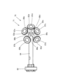
- Figure 25 is a left side view of the first pressing portion of the second embodiment
- Figure 26 is a cross-sectional view taken along line CC of Figure 25.
- the work connection device 21 of this embodiment uses a multi-joint robot 9 for the welding machine, a first pressing multi-joint robot 3, and a second pressing and third pressing mechanism 7 to bias and connect a second work W2 to a first work W1 fixed on a mounting table 88 arranged in a housing H.
- the first pressing portion 25 of this embodiment presses the back surface of the first workpiece W1 when the welding articulated robot 9 welds the second workpiece W2 to the first workpiece W1.
- the first holding part 25 of this embodiment is composed of a first mounting part 62 connected to the fifth rotation axis 39 of the first holding articulated robot 3, a long arm 64 having one end connected to the first mounting part 62, a second mounting part 66 connected to the other end of the arm 64 by five attachments 66a, 66b, 66c, 66d and 66e (66c to 66e are not shown), and a support 66 connected to the second mounting part 66.
- the support 66 is a polyhedron consisting of 14 roughly triangular flat first plates 63a, 63b, 63c, 63d (not shown), 63e, 63f, 63g, 63h, 63j (not shown), 63k (not shown), 63m, 63x, 63y and 63z (not shown), and flat disks 65a (not shown), 65b, 65c, 65d (not shown), 65e, 65f, 65g, 65h, 65j (not shown), 65k (not shown) and 65m of a predetermined thickness are fixed to the surface of each first plate of the polyhedron except for 63x, 63y and 63z within the roughly triangular periphery of the first plate.
- the first plate 63a is shown in a state before the disk 65a is attached, but in reality, the disk 65a is attached to the first plate 63a as well, just like the other first plates.
- the normals of the first plates 63a, 63b, 63c, 63d, 63e, 63f, 63g, 63h, 63j, 63k, 63m, 63x, 63y and 63z are arranged so that each of them faces in a different direction.
- the support 66 also has an opening surface 61b (not shown) formed by a housing 61a (not shown) and a cavity 61c (not shown) inside the polyhedron, and as shown in Figure 26, each of the disks 65a (not shown), 65b, 65c, 65d (not shown), 65e, 65f, 65g, 65h, 65j (not shown), 65k (not shown) and 65m
- Each consists of a disk body 65aa, 65ba, 65ca, 65da, 65ea, 65fa, 65ga, 65ha, 65ja, 65ka, and 65ma (not shown except for 65ea), and threaded portions 65ab, 65bb, 65cb, 65db, 65eb, 65fb, 65gb, 65hb, 65jb, 65k
- each of the disks 65a (not shown), 65b, 65c, 65d (not shown), 65e, 65f, 65g, 65h, 65j (not shown), 65k (not shown) and 65m is connected to the fasteners 68aa, 68ba, 68ca, 68da, 68ea, 68fa, 68ga, 68ha, 68ja, 68ka and 68ma (not shown except for 68ea) and washers 68ab, 68bb, 68cb, 68db ...
- 8eb, 68fb, 68gb, 68hb, 68jb, 68kb, and 68mb are individually sandwiched through holes 69a, 69b, 69c, 69d, 69e, 69f, 69g, 69h, 69j, 69k, and 69m (not shown except for 69e) of first plates 63a, 63b, 63c, 63d, 63e, 63f, 63g, 63h, 63j, 63k, and 63m.
- the first pressing portion 25 is abutted against the back surface of the first workpiece W1 using the disk selected from disks 65a, 65b, 65c, 65d, 65e, 65f, 65g, 65h, 65j, 65k, and 65m by the above-mentioned first pressing portion selection program.
- the workpiece connecting device 21 of this embodiment is intended for connecting the second workpiece W2 to the surface of the first workpiece W1 by pressing the second workpiece W2 against the surface of the first workpiece W1, and is particularly equipped with a first pressing articulated robot 3 and a support 66 that is connected to the tip of the first pressing articulated robot 3 and can abut against the back surface of the first workpiece W1. Therefore, even if the first workpiece W1 has a complex shape, an appropriate support 66 can be abutted against the back surface of the first workpiece W1, and thus the second workpiece W2 can be quickly connected to the surface of the first workpiece W1.
- the support 66 is made up of a plurality of first plates 63a, 63b, 63c, 63d, 63e, 63f, 63g, 63h, 63j, 63k, and 63m arranged with normals pointing in multiple directions. Therefore, even if the first work W1 has a complex shape, an appropriate first plate can be selected and abutted against the back surface of the first work W1, and thus the second work W2 can be efficiently connected to the front surface of the first work W1. Furthermore, even if one first plate becomes unusable, the other first plate can be used, improving the durability of the device.
- a polyhedron is connected to the tip of the first pressing articulated robot 3, and each of the first plates 63a, 63b, 63c, 63d, 63e, 63f, 63g, 63h, 63j, 63k and 63m is separately connected to one face constituting the polyhedron, so that a structure can be easily created in which an appropriate first plate can be selected and abutted even against a first workpiece W1 having a complex shape.
- the polyhedron has an opening surface 61b (not shown) and an internal cavity 61c (not shown), and each of the disks 65a, 65b, 65c, 65d, 65e, 65f, 65g, 65h, 65j, 65k, and 65m is connected to the fasteners 68aa, 68ba, 68ca, 68da, 68ea, 68fa, 68ga, 68ha, 68ja, from the cavity 61c.
- first plates 63a, 63b, 63c, 63d, 63e, 63f, 63g, 63h, 63j, 63k, and 63m by 68ka and 68ma (not shown except for 68ea) and is separately connected to one face that constitutes the polyhedron, it is easy to create a structure in which an appropriate first plate can be selected and firmly abutted against the first workpiece W1, even if the first workpiece W1 has a complex shape.
- the third embodiment of the present invention will be described below.
- the work connection device 61 of this embodiment is similar to the work connection device 1 of the first embodiment except for the first pressing portion, so the parts common to the first embodiment are given the same reference numerals and the description will be omitted.
- Figure 27 is a left side view of the first pressing part of the third embodiment.
- the work connection device 61 of this embodiment uses a multi-joint robot 9 for the welding machine, a first pressing multi-joint robot 3, and a second pressing and third pressing mechanism 7 to bias and connect a second work W2 to a first work W1 fixed on a mounting table 88 arranged in a housing H.
- the first pressing portion 45 of this embodiment presses the back surface of the first workpiece W1 when the welding articulated robot 9 welds the second workpiece W2 to the first workpiece W1.
- the first holding part 45 of this embodiment is composed of a first mounting part 72 connected to the fifth rotation axis 39 of the first holding articulated robot 3, a long arm 74 having one end connected to the first mounting part 72, a second mounting part 76 connected to the other end of the arm 74 by five mounting fixtures 76a, 76b, 76c, 76d and 76e (76c to 76e are not shown), and a support 77 connected to the second mounting part 76.
- the support 77 is a polyhedron made up of 14 roughly triangular flat first plates 73a, 73b, 73c, 73d (not shown), 73e, 73f, 73g, 73h, 73j (not shown), 73k (not shown), 73m (not shown), 73x, 73y and 73z (not shown).
- the normals of the first plates 73a, 73b, 73c, 73d, 73e, 73f, 73g, 73h, 73j, 73k, 73m, 73x, 73y and 73z are arranged so that each of them faces in a different direction.
- the support 77 has an opening surface 71b (not shown) formed by a housing 71a (not shown) and a cavity 71c (not shown) inside the polyhedron.
- the first pressing portion 45 contacts the rear surface of the first workpiece W1 with the first plate selected from the first plates 73a, 73b, 73c, 73d, 73e, 73f, 73g, 73h, 73j, 73k, and 73m by the above-mentioned first pressing portion selection program.
- the workpiece connecting device 61 of this embodiment is intended for connecting the second workpiece W2 to the surface of the first workpiece W1 by pressing the second workpiece W2 against the surface of the first workpiece W1, and is particularly equipped with a first pressing articulated robot 3 and a support 77 that is connected to the tip of the first pressing articulated robot 3 and can abut against the back surface of the first workpiece W1. Therefore, even if the first workpiece W1 has a complex shape, an appropriate support 77 can be abutted against the back surface of the first workpiece W1, and thus the second workpiece W2 can be quickly connected to the surface of the first workpiece W1.
- the support 77 is made up of a plurality of first plates 73a, 73b, 73c, 73d, 73e, 73f, 73g, 73h, 73j, 73k, and 73m arranged with normals pointing in multiple directions. Therefore, even if the first work W1 has a complex shape, an appropriate first plate can be selected and abutted against the back surface of the first work W1, and thus the second work W2 can be efficiently connected to the front surface of the first work W1. Furthermore, even if one first plate becomes unusable, the other first plate can be used, improving the durability of the device.
- a polyhedron is connected to the tip of the first pressing articulated robot 3, and each of the first plates 73a, 73b, 73c, 73d, 73e, 73f, 73g, 73h, 73j, 73k and 73m is separately connected to one face that constitutes the polyhedron, so that a structure can be easily created in which an appropriate first plate can be selected and abutted even against a first workpiece W1 having a complex shape.
- the work connection device 71 of this embodiment is similar to the work connection device 1 of the first embodiment except for the first pressing portion, so the parts common to the first embodiment are given the same reference numerals and the description will be omitted.
- Figure 28 is a left side view of the first pressing part of the fourth embodiment.
- the work connection device 71 of this embodiment uses a multi-joint robot 9 for the welding machine, a first pressing multi-joint robot 3, and a second pressing and third pressing mechanism 7 to bias and connect a second work W2 to a first work W1 fixed on a mounting table 88 arranged in a housing H.
- the first pressing portion 75 of this embodiment presses the back surface of the first workpiece W1 when the welding articulated robot 9 welds the second workpiece W2 to the first workpiece W1.
- the first pressing unit 75 of this embodiment includes a first mounting unit 82 connected to the fifth rotation axis 39 of the first pressing articulated robot 3, a long arm 84 having one end connected to the first mounting unit 82, five shafts 86a, 86b, 86c, 86d, and 86e connected to the other end of the arm 84, first plates (corresponding to the "support" of the present invention) 83a, 83b, 83c, 83d, and 83e of a predetermined thickness that are connected to the tips of each of the five shafts 86a, 86b, 86c, 86d, and 86e, and protrusions 87a, 87b, 87c, 87d, and 87e that are circular in plan view and have central portions that protrude radially from the arm 84 and are arranged on the surfaces of each of the first plates 83a, 83b, 83c, 83d, and 83e.
- the normals of the disk-shaped first plates (corresponding to the "support” of the present invention) 83a, 83b, 83c, 83d, and 83e are arranged so that they each point in a different direction.
- the first pressing portion 75 contacts the back surface of the first workpiece W1 with the first plate (support) selected from the first plates (corresponding to the "support” of the present invention) 83a, 83b, 83c, 83d, and 83e by the above-mentioned first pressing portion selection program.
- the workpiece connecting device 71 of this embodiment is intended for connecting the second workpiece W2 to the surface of the first workpiece W1 by pressing the second workpiece W2 against the surface of the first workpiece W1, and is particularly equipped with a first pressing articulated robot 3 and supports 83a, 83b, 83c, 83d, and 83e that are connected to the tip of the first pressing articulated robot 3 and can abut against the back surface of the first workpiece W1. Therefore, even if the first workpiece W1 has a complex shape, the appropriate supports 83a, 83b, 83c, 83d, and 83e can be abutted against the back surface of the first workpiece W1, and thus the second workpiece W2 can be quickly connected to the surface of the first workpiece W1.
- the first plates 83a, 83b, 83c, 83d, and 83e are arranged so that their normals point in multiple directions, so that even if the first work W1 has a complex shape, an appropriate first plate can be selected and abutted against the back surface of the first work W1, and ultimately the second work W2 can be efficiently connected to the front surface of the first work W1. Furthermore, even if one first plate becomes unusable, the other first plate can be used, improving the durability of the device.
- the first plates 83a, 83b, 83c, 83d, and 83e have protruding portions 87a, 87b, 87c, 87d, and 87e that are circular in plan view and protrude from the center, thereby preventing distortion that occurs on the surface of the first workpiece W1 and/or the surface of the second workpiece W2 during welding, thereby improving the appearance quality of the entire workpiece including the first workpiece W1 and the second workpiece W2.
- the work connection device 81 of this embodiment is similar to the work connection device 1 of the first embodiment except for the first pressing portion, so the parts common to the first embodiment are given the same reference numerals and the description will be omitted.
- Figure 29 is a left side view of the first pressing part of the fifth embodiment.
- the work connection device 81 of this embodiment uses a multi-joint robot 9 for the welding machine, a first pressing multi-joint robot 3, and a second pressing and third pressing mechanism 7 to bias and connect a second work W2 to a first work W1 fixed on a mounting table 88 arranged in a housing H.
- the first pressing portion 85 of this embodiment presses the back surface of the first workpiece W1 when the welding articulated robot 9 welds the second workpiece W2 to the first workpiece W1.
- the first holding unit 85 of this embodiment includes a first mounting unit 102 connected to the fifth rotation axis 39 of the first holding articulated robot 3, a long arm 104 having one end connected to the first mounting unit 102, a second mounting unit 106 connected to the other end of the arm 104 by five attachments 106a, 106b, 106c, 106d, and 106e (106c to 106e are not shown), and a support 103 connected to the second mounting unit 106.
- the support 103 has a hemispherical shape.
- the first pressing portion 85 in this embodiment abuts so that the normal to the front surface of the support 103 coincides with the normal to the rear surface of the first workpiece W1.
- the workpiece connecting device 81 of this embodiment is intended for connecting the second workpiece W2 to the surface of the first workpiece W1 by pressing the second workpiece W2 against the surface of the first workpiece W1, and is particularly equipped with a first holding articulated robot 3 and a support 103 that is connected to the tip of the first holding articulated robot 3 and can abut against the back surface of the first workpiece W1. Therefore, even if the first workpiece W1 has a complex shape, the support 103 can be abutted against the back surface of the first workpiece W1, and thus the second workpiece W2 can be quickly connected to the surface of the first workpiece W1.
- the work connection device 101 of this embodiment is similar to the work connection device 1 of the first embodiment except for the second holding portion and the third holding portion. Therefore, the parts common to the first embodiment are given the same reference numerals and the description will be omitted.
- Figure 30 is a side view showing the second pressing portion of the sixth embodiment.
- the work connection device 101 of this embodiment uses a multi-joint robot 9 for the welding machine, a first pressing multi-joint robot 3, and a second pressing and third pressing mechanism 7 to bias and connect a second work W2 to a first work W1 fixed on a mounting table 88 arranged in a housing H.
- the second pressing portion 7c of this embodiment presses the back surface of the first workpiece W1 when the welding articulated robot 9 welds the second workpiece W2 to the first workpiece W1.
- the second pressing portion 7c includes a first base 11, a telescopic rod 15 that extends and retracts relative to the first base 11, a compression spring (not shown) disposed inside the telescopic rod 15 and biasing the telescopic rod 15 upward, a second pressing cylinder 42 that causes the telescopic rod 15 to extend and retract relative to the first base 11, a second vertical fixing solenoid valve 28 disposed on the top of the first base 11 for fixing the vertical position of the telescopic rod 15, a second base 13 fixed to the top end of the telescopic rod 15, a swivel fixing solenoid valve 26 disposed on the top of the second base 13 for fixing the swivel of a second pressing suction portion 46 described later, a telescopic portion 17 disposed on the top of the swivel fixing solenoid valve 26 and capable of extending and retracting, a second pressing suction portion 46 (corresponding to the "second plate" of the present invention) disposed on the top of the telescopic
- the second holding portion 7c configured as described above, like the second holding portion 7a of the first embodiment, first lowers the second base portion 13, the second swivel fixing solenoid valve 26, the expansion/contraction portion 17, and the second holding suction portion 46 in the -Y direction by the second holding cylinder 42, and then fixes the expansion rod 15 in the lowered position with the compression spring compressed by the second up/down fixing solenoid valve 28.
- the second pressing part 7c is moved below the connection position using the second pressing slide motor 22, and then the second up-down fixing solenoid valve 28 is released, and the second base 13, the second swivel fixing solenoid valve 26, the expansion/contraction part 17, the second pressing suction part 46 and the protrusion 49 are raised in the +Y direction by the force of the compression spring, and the second pressing suction part 46 and the protrusion 49 are brought into contact with the back surface of the first workpiece W1.
- the second pressing portion 7c is configured to be movable in the +X direction or the -X direction on the right mounting table 88b fixed to the mounting table 88 by using a second pressing slide motor 22 arranged near the right mounting table 88b and a ball screw arranged inside the right mounting table 88b.
- the rotational force of a motor gear fixed to the motor shaft of the second pressing slide motor 22 is transmitted to the ball screw.
- the second clamping portion 7c can also be used in place of the third clamping portion 7b.
- the workpiece connecting device 101 of this embodiment is intended for connecting the second workpiece W2 to the surface of the first workpiece W1 by pressing the second workpiece W2 against the surface of the first workpiece W1, and is particularly equipped with one movable second pressing suction part 46 that can contact the back surface of the first workpiece W1 and whose normal can be changed in multiple directions. Since the direction of the normal of the second pressing suction part 46 can be fixed when it contacts the back surface of the first workpiece W1, the second pressing suction part 46 can be appropriately contacted with the back surface of the first workpiece W1 even if the first workpiece W1 has a complex shape, and thus the second workpiece W2 can be quickly connected to the surface of the first workpiece W1.
- the second pressing suction portion 46 has a protruding portion 49 with a protruding central portion, which prevents distortion from occurring on the surface of the first workpiece W1 and/or the surface of the second workpiece W2 during welding, thereby improving the appearance quality of the entire workpiece including the first workpiece W1 and the second workpiece W2.
- the present invention is not limited to this, and can be applied to any connection, including crimping, pressure welding, etc., as long as the second workpiece W2 is connected to the first workpiece by pressing it against it.
- the support body is described as a 14-sided polyhedron, and the shape of the first plate constituting the polyhedron is described as being approximately triangular, but this is not limited thereto, and the polyhedron may be a polyhedron with two or more sides, and may be partially curved. Furthermore, the shape of the first plate constituting the polyhedron may be any shape.
- the shape of the first plates that make up the polyhedron is a uniform shape, and it is better for the polyhedron to be made up of first plates with that uniform shape.
- the support is described as having a hemispherical shape, but this is not limited thereto, and may be, for example, a shape in which two or more planes are folded into a V shape.
- the second holding portion 7a and the third holding portion 7b have been described as moving in a linear direction, but this is not limited thereto, and the direction of movement can be changed as appropriate depending on the specifications of the work connection device.
- Second swivel fixing solenoid valve 28 Second vertical fixing solenoid valve 30: Third swivel fixing solenoid valve 40: Third vertical fixing solenoid valve 42: Second pressing cylinder 44: Third pressing cylinder 46: Second pressing suction portion 48: Third pressing suction portion 49, 57, 87: Protrusions 51, 66, 77, 83, 103: Support body 51b: Opening surface 51c: Cavity 53, 63, 73, 83: First plate 55, 65: Disc 58: Fastener W1: First workpiece W2: Second workpiece
Landscapes
- Engineering & Computer Science (AREA)
- Mechanical Engineering (AREA)
- Physics & Mathematics (AREA)
- Optics & Photonics (AREA)
- Robotics (AREA)
- Plasma & Fusion (AREA)
- Pressure Welding/Diffusion-Bonding (AREA)
- Lining Or Joining Of Plastics Or The Like (AREA)
- Automatic Assembly (AREA)
- Manipulator (AREA)
Abstract
Description
先ず、本発明の第1実施形態について説明する。なお、本実施形態に使用する図面は、理解を容易にするために誇張して表現されており、その寸法は実際の寸法とは異なる。
次に、本発明の第2実施形態について説明する。なお、本実施形態に使用する図面も、理解を容易にするために誇張して表現されており、その寸法は実際の寸法とは異なる。
次に、本発明の第3実施形態について説明する。なお、本実施形態に使用する図面も、理解を容易にするために誇張して表現されており、その寸法は実際の寸法とは異なる。
次に、本発明の第4実施形態について説明する。なお、本実施形態に使用する図面も、理解を容易にするために誇張して表現されており、その寸法は実際の寸法とは異なる。
次に、本発明の第5実施形態について説明する。なお、本実施形態に使用する図面も、理解を容易にするために誇張して表現されており、その寸法は実際の寸法とは異なる。
最後に、本発明の第6実施形態について説明する。なお、本実施形態に使用する図面も、理解を容易にするために誇張して表現されており、その寸法は実際の寸法とは異なる。
3・・・第1押さえ用多関節ロボット
4・・・エアコンプレッサー
5,25,45,75,85・・・第1押さえ部
7・・・第2押さえ・第3押さえ機構
7a,7c・・・第2押さえ部
7b・・・第3押さえ部
9・・・溶着機用多関節ロボット
12・・・ロボットコントローラ
20・・・超音波振動子
22・・・第2押さえ用スライドモータ
24・・・第3押さえ用スライドモータ
26・・・第2首振り固定用電磁弁
28・・・第2上下固定用電磁弁
30・・・第3首振り固定用電磁弁
40・・・第3上下固定用電磁弁
42・・・第2押さえ用シリンダ
44・・・第3押さえ用シリンダ
46・・・第2押さえ吸引部
48・・・第3押さえ吸引部
49,57,87・・・突出部
51,66,77,83,103・・・支持体
51b・・・開口面
51c・・・空洞
53,63,73,83・・・第1のプレート
55,65・・・円板
58・・・締め具
W1・・・第1のワーク
W2・・・第2のワーク
Claims (7)
- 第1のワークの表面に第2のワークを付勢して、前記第1のワークの表面に前記第2のワークを接続するワーク接続装置において、
多関節ロボットと、
その多関節ロボットの先端に接続され、前記第1のワークの裏面に当接可能な支持体と、
を備えたことを特徴とするワーク接続装置。 - 前記支持体は、法線が複数の方向に向かうように配置された複数の第1のプレートを備えたことを特徴とする請求項1に記載のワーク接続装置。
- 前記多関節ロボットの先端には多面体が接続され、
前記複数の第1のプレートの各々は、前記多面体を構成する1つの面に別個に接続されていることを特徴とする請求項2に記載のワーク接続装置。 - 前記多面体は、開口面と、内部に空洞とを有し、
前記複数の第1のプレートの各々は、前記空洞からの締め具によって前記多面体に挟持され、前記多面体を構成する1つの面に別個に接続されていることを特徴とする請求項3に記載のワーク接続装置。 - 前記第1のプレートは、中央部が突出した構造を呈していることを特徴とする請求項2乃至請求項4の何れかに記載のワーク接続装置。
- 第1のワークの表面に第2のワークを付勢して、前記第1のワークの表面に前記第2のワークを接続するワーク接続装置において、
移動体と、
その移動体上に配置され、前記第1のワークの裏面に当接可能であって、法線が複数の方向に変更可能な少なくとも1つの第2のプレートと、
を備え、
少なくとも1つの前記第2のプレートは、前記第1のワークの裏面に当接したときに、法線の方向が固定可能であることを特徴とするワーク接続装置。 - 前記第2のプレートは、中央部が突出した構造を呈していることを特徴とする請求項6に記載のワーク接続装置。
Priority Applications (4)
| Application Number | Priority Date | Filing Date | Title |
|---|---|---|---|
| CN202380096602.9A CN121079172A (zh) | 2023-05-09 | 2023-05-09 | 工件连接装置 |
| JP2023552495A JP7589956B1 (ja) | 2023-05-09 | 2023-05-09 | ワーク接続装置 |
| PCT/JP2023/017396 WO2024232004A1 (ja) | 2023-05-09 | 2023-05-09 | ワーク接続装置 |
| US19/334,115 US20260014654A1 (en) | 2023-05-09 | 2025-09-19 | Workpiece connecting apparatus |
Applications Claiming Priority (1)
| Application Number | Priority Date | Filing Date | Title |
|---|---|---|---|
| PCT/JP2023/017396 WO2024232004A1 (ja) | 2023-05-09 | 2023-05-09 | ワーク接続装置 |
Related Child Applications (1)
| Application Number | Title | Priority Date | Filing Date |
|---|---|---|---|
| US19/334,115 Continuation US20260014654A1 (en) | 2023-05-09 | 2025-09-19 | Workpiece connecting apparatus |
Publications (1)
| Publication Number | Publication Date |
|---|---|
| WO2024232004A1 true WO2024232004A1 (ja) | 2024-11-14 |
Family
ID=93431474
Family Applications (1)
| Application Number | Title | Priority Date | Filing Date |
|---|---|---|---|
| PCT/JP2023/017396 Ceased WO2024232004A1 (ja) | 2023-05-09 | 2023-05-09 | ワーク接続装置 |
Country Status (4)
| Country | Link |
|---|---|
| US (1) | US20260014654A1 (ja) |
| JP (1) | JP7589956B1 (ja) |
| CN (1) | CN121079172A (ja) |
| WO (1) | WO2024232004A1 (ja) |
Citations (4)
| Publication number | Priority date | Publication date | Assignee | Title |
|---|---|---|---|---|
| JP2003019573A (ja) * | 2001-07-05 | 2003-01-21 | Toshiba Corp | 超音波による接続用部品と部品接続装置 |
| JP2014104493A (ja) * | 2012-11-28 | 2014-06-09 | Primearth Ev Energy Co Ltd | 電池用極板製造装置の検査方法及び検査装置 |
| JP2015047629A (ja) * | 2013-09-04 | 2015-03-16 | ブランソン・ウルトラソニックス・コーポレーション | 超音波溶着用アンビル |
| JP2022102586A (ja) * | 2020-12-25 | 2022-07-07 | 株式会社豊電子工業 | 振動溶着システム及び振動溶着方法 |
Family Cites Families (2)
| Publication number | Priority date | Publication date | Assignee | Title |
|---|---|---|---|---|
| JP3234520B2 (ja) * | 1997-01-07 | 2001-12-04 | 株式会社オートネットワーク技術研究所 | 超音波溶接装置 |
| US8925612B2 (en) * | 2013-02-25 | 2015-01-06 | Branson Ultrasonics Corporation | Ultrasonic collet horn for ultrasonic welder |
-
2023
- 2023-05-09 WO PCT/JP2023/017396 patent/WO2024232004A1/ja not_active Ceased
- 2023-05-09 CN CN202380096602.9A patent/CN121079172A/zh active Pending
- 2023-05-09 JP JP2023552495A patent/JP7589956B1/ja active Active
-
2025
- 2025-09-19 US US19/334,115 patent/US20260014654A1/en active Pending
Patent Citations (4)
| Publication number | Priority date | Publication date | Assignee | Title |
|---|---|---|---|---|
| JP2003019573A (ja) * | 2001-07-05 | 2003-01-21 | Toshiba Corp | 超音波による接続用部品と部品接続装置 |
| JP2014104493A (ja) * | 2012-11-28 | 2014-06-09 | Primearth Ev Energy Co Ltd | 電池用極板製造装置の検査方法及び検査装置 |
| JP2015047629A (ja) * | 2013-09-04 | 2015-03-16 | ブランソン・ウルトラソニックス・コーポレーション | 超音波溶着用アンビル |
| JP2022102586A (ja) * | 2020-12-25 | 2022-07-07 | 株式会社豊電子工業 | 振動溶着システム及び振動溶着方法 |
Also Published As
| Publication number | Publication date |
|---|---|
| CN121079172A (zh) | 2025-12-05 |
| JP7589956B1 (ja) | 2024-11-26 |
| JPWO2024232004A1 (ja) | 2024-11-14 |
| US20260014654A1 (en) | 2026-01-15 |
Similar Documents
| Publication | Publication Date | Title |
|---|---|---|
| US5132887A (en) | Multi-articulation type robot for laser operation | |
| KR20080114827A (ko) | 구성요소를 클램핑하고 고정할 수 있는 클램핑 장치 | |
| JP2017164828A (ja) | ワーク加工ロボットの加工ヘッド | |
| JP2017164828A5 (ja) | ||
| JP7589956B1 (ja) | ワーク接続装置 | |
| WO2020161881A1 (ja) | ラッピング治具、ラッピング装置およびラッピング方法 | |
| EP0585463A1 (en) | Method of adjusting optical axis for laser robot | |
| JP2007167896A (ja) | シーム溶接機、シーム溶接装置、シーム溶接ロボットシステム、シーム溶接方法及びローラ電極の回転駆動制御プログラム作成方法 | |
| JP2019209422A (ja) | 多関節ロボット用の教示データ作成方法 | |
| JP3438548B2 (ja) | スポット溶接用ロボットハンドおよびこのロボットハンドによるワーク把持方法 | |
| KR100504036B1 (ko) | 본딩장치 | |
| JP2000162133A (ja) | 基板検査装置および該基板検査装置に用いられるパラレルリンク機構 | |
| JPH06134683A (ja) | 7自由度マニピュレータアームのマスタリング法 | |
| JP2005230877A (ja) | ワーク位置決め装置およびワーク位置決め方法 | |
| JP7550447B2 (ja) | 振動溶着システム及び振動溶着方法 | |
| JPH05337856A (ja) | 産業用多関節ロボットのマスタリング装置 | |
| JP7459265B2 (ja) | 基板保持ハンドおよび基板搬送ロボット | |
| JP2005288550A (ja) | 精密研削装置および精密研削方法 | |
| JP2011224624A (ja) | 接合装置及び接合方法 | |
| JPH08323661A (ja) | 自動組付機 | |
| JPH02147810A (ja) | 三次元測定装置 | |
| JP2992819B1 (ja) | 空洞部を有する立体物の製造装置 | |
| JP2009039787A (ja) | スカラロボット | |
| JP4161838B2 (ja) | 部品組付装置および回転電機の製造方法 | |
| JP7514470B2 (ja) | ヘム加工装置、および、加工方法 |
Legal Events
| Date | Code | Title | Description |
|---|---|---|---|
| WWE | Wipo information: entry into national phase |
Ref document number: 2023552495 Country of ref document: JP |
|
| 121 | Ep: the epo has been informed by wipo that ep was designated in this application |
Ref document number: 23936558 Country of ref document: EP Kind code of ref document: A1 |
|
| WWE | Wipo information: entry into national phase |
Ref document number: CN2023800966029 Country of ref document: CN |
|
| NENP | Non-entry into the national phase |
Ref country code: DE |
|
| 122 | Ep: pct application non-entry in european phase |
Ref document number: 23936558 Country of ref document: EP Kind code of ref document: A1 |