WO2024228248A1 - 緩衝装置、懸架装置 - Google Patents
緩衝装置、懸架装置 Download PDFInfo
- Publication number
- WO2024228248A1 WO2024228248A1 PCT/JP2023/017106 JP2023017106W WO2024228248A1 WO 2024228248 A1 WO2024228248 A1 WO 2024228248A1 JP 2023017106 W JP2023017106 W JP 2023017106W WO 2024228248 A1 WO2024228248 A1 WO 2024228248A1
- Authority
- WO
- WIPO (PCT)
- Prior art keywords
- elastic member
- rod
- piston portion
- collar
- piston
- Prior art date
- Legal status (The legal status is an assumption and is not a legal conclusion. Google has not performed a legal analysis and makes no representation as to the accuracy of the status listed.)
- Ceased
Links
Images




Classifications
-
- F—MECHANICAL ENGINEERING; LIGHTING; HEATING; WEAPONS; BLASTING
- F16—ENGINEERING ELEMENTS AND UNITS; GENERAL MEASURES FOR PRODUCING AND MAINTAINING EFFECTIVE FUNCTIONING OF MACHINES OR INSTALLATIONS; THERMAL INSULATION IN GENERAL
- F16F—SPRINGS; SHOCK-ABSORBERS; MEANS FOR DAMPING VIBRATION
- F16F9/00—Springs, vibration-dampers, shock-absorbers, or similarly-constructed movement-dampers using a fluid or the equivalent as damping medium
- F16F9/32—Details
- F16F9/48—Arrangements for providing different damping effects at different parts of the stroke
- F16F9/49—Stops limiting fluid passage, e.g. hydraulic stops or elastomeric elements inside the cylinder which contribute to changes in fluid damping
-
- F—MECHANICAL ENGINEERING; LIGHTING; HEATING; WEAPONS; BLASTING
- F16—ENGINEERING ELEMENTS AND UNITS; GENERAL MEASURES FOR PRODUCING AND MAINTAINING EFFECTIVE FUNCTIONING OF MACHINES OR INSTALLATIONS; THERMAL INSULATION IN GENERAL
- F16F—SPRINGS; SHOCK-ABSORBERS; MEANS FOR DAMPING VIBRATION
- F16F9/00—Springs, vibration-dampers, shock-absorbers, or similarly-constructed movement-dampers using a fluid or the equivalent as damping medium
- F16F9/32—Details
- F16F9/3207—Constructional features
- F16F9/3235—Constructional features of cylinders
- F16F9/3257—Constructional features of cylinders in twin-tube type devices
Definitions
- the present invention relates to shock absorbers and suspension systems.
- the vibration damper described in Patent Document 1 is configured as follows: A first piston is fixed to a piston rod that is movable axially within the cylinder. A second piston is attached to the piston rod. The second piston enters a pressure cylinder with a pressure chamber according to the stroke. The second piston has a throttle opening through which the damping medium moves. A pin penetrating axially is provided in the center of the bottom of the pressure cylinder, and a pressure limiting valve is provided that opens in the flow direction from the pressure cylinder to the base valve body.
- the pressure limiting valve has a spherical valve and a spring that exerts a force on the valve in a direction that closes the flow path.
- the pressure limiting valve described in Patent Document 1 prevents the pressure in the cylinder from becoming too high by opening and letting the damping medium flow out of the pressure cylinder when the internal pressure reaches a set value during the compression stroke in which the piston rod moves in the direction into the cylinder.
- This pressure limiting valve is provided at the bottom of the pressure cylinder, so it is difficult to apply it to the extension stroke in which the piston rod moves out of the cylinder.
- the cylinder is turned upside down, and in this case, a separate hole through which the piston rod passes is required at the bottom. This hole needs to be airtight with respect to the piston rod so that the pressure control valve can function.
- the press-in control valve needs to be offset so that the pressure limiting valve does not interfere with the piston rod.
- the present invention aims to provide a shock absorber etc. that allows for highly flexible layout design while preventing the pressure inside the cylinder from becoming too high during the extension stroke, thereby allowing for highly flexible setting of damping force characteristics.
- the present invention which was completed with this objective in mind, comprises a rod, a portion of which is inserted into a cylindrical cylinder, a first piston portion fixed to the rod and defining a space within the cylinder, a cylindrical collar disposed on the rod side of the first piston portion within the cylinder, and a second piston portion fixed to the rod coaxially with the first piston portion and capable of entering the collar to form a high-pressure chamber in the space within the collar, the high-pressure chamber having a higher pressure than the first piston portion side, the second piston portion comprising an annular elastic member and a second piston portion configured to be elastically movable relative to the elastic member in the axial direction of the rod.
- the shock absorber has a seal member that is arranged on the opposite side of the first piston portion and can contact the inner circumferential surface of the collar, and a restricting member that restricts the axial movement of the elastic member and the seal member, the seal member having a cylindrical base and a protrusion that protrudes from the outer circumferential portion of the opposing surface of the base that faces the elastic member toward the elastic member and can contact the outer circumferential portion of the elastic member, the base has a recess formed inside the protrusion that is recessed from the opposing surface to the opposite side of the elastic member, and the protrusion has a groove formed in at least a portion of the circumferential direction that connects the inside and outside.
- the present invention provides a shock absorber and the like that allows for highly flexible layout design while preventing the pressure inside the cylinder from becoming too high during the extension stroke, allowing for highly flexible setting of damping force characteristics.
- FIG. 1 is a diagram illustrating an example of a schematic configuration of a suspension device.
- FIG. 2 is an example of an enlarged view of a part II in FIG. 4 is a view of an example of a seal member as viewed from a first side in an axial direction; 13 is an example of a cross-sectional view of the second piston portion during an extension stroke in which the amount by which the rod protrudes from the cylinder portion increases.
- FIG. FIG. 5 is an example of an enlarged view of a V portion of FIG. 4 .
- FIG. 4 is an example of a cross-sectional view of the second piston portion during an extension stroke.
- 11 is an example of a cross-sectional view of the second piston portion during a compression stroke in which the amount of protrusion of the rod decreases.
- FIG. FIG. 13 is a diagram showing an example of a schematic configuration of a second piston portion according to a second embodiment.
- 11A and 11B are diagrams illustrating an example of a state of the second piston portion during a compression stroke in which the amount of protrusion of the rod decreases.
- FIG. 13 is a diagram showing an example of a schematic configuration of a second piston portion according to a third embodiment.
- 13 is a diagram illustrating an example of an elastic member according to the third embodiment, as viewed in an axial direction.
- FIG. FIG. 13 is a diagram illustrating an example of a schematic configuration of a shock absorber according to a fourth embodiment.
- FIG. 4 is an example of a cross-sectional view of a third piston portion during a compression stroke.
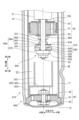
- FIG. 1 is a diagram showing an example of a schematic configuration of a suspension system 1.
- the suspension system 1 is a strut-type suspension used in four-wheeled vehicles such as passenger automobiles, and as shown in Fig. 1, comprises a shock absorber 2 and a coil spring 3 arranged on the outside of the shock absorber 2.
- the suspension system 1 also comprises a lower spring seat 4 that supports an end of the coil spring 3 on a first axial side (lower side in Fig. 1) of a rod 20 described below, and an upper spring seat 5 that supports an end of the coil spring 3 on a second axial side (upper side in Fig. 1).
- the suspension 1 also includes a vehicle body side mounting bracket 6 that is attached to the second axial end of the rod 20 for mounting the suspension 1 to a vehicle, and a wheel side mounting bracket 7 that is fixed to the first axial end of the rod 20 in the cylinder portion 10 (described later) for mounting the suspension 1 to a wheel.
- the suspension 1 also includes a dust cover 8 that covers at least a portion of the cylinder portion 10 and the rod 20.
- the axial direction of the rod 20 may be simply referred to as the "axial direction”.
- the axial direction is also the direction of the center line of the cylindrical cylinder 11, which will be described later.
- the first axial side (lower side in FIG. 1) and the second axial side (upper side in FIG. 1) may be simply referred to as the “first side” and the “second side", respectively.
- the direction that intersects with the axial direction e.g., the perpendicular direction
- the side of the center line of the cylinder 11 may be simply referred to as the "inner side”
- the side away from the center line may be simply referred to as the "outer side".
- the shock absorber 2 includes a cylinder portion 10 that contains oil, and a rod 20 whose second end protrudes from the cylinder portion 10 and whose first end is slidably inserted into the cylinder portion 10.
- the shock absorber 2 also includes a first piston portion 30 provided at the first end of the rod 20, and a bottom valve 40 provided at the first end of the cylinder portion 10.
- the shock absorber 2 also includes a second piston portion 100 provided on the second side of the first piston portion 30.
- the cylinder section 10 includes a cylinder 11 that contains oil, an outer cylinder body 12 that is provided on the outside of the cylinder 11, and a bottom cover 13 that closes a first end of the outer cylinder body 12.
- the cylinder 11 and the outer cylinder body 12 are arranged so that the center line direction of the cylinder coincides with the axial direction.
- the cylinder section 10 forms a reservoir chamber R with the outer peripheral surface of the cylinder 11 and the inner peripheral surface of the outer cylinder body 12.
- the outer cylinder body 12 is filled with oil, which is an example of a fluid.
- the cylinder section 10 also includes a rod guide section 14 that movably supports the rod 20, a bump stopper cap 15 attached to the second end of the outer cylinder body 12, and an oil seal 16 that prevents oil leakage from the cylinder section 10 and foreign matter from entering the cylinder section 10.
- the cylinder section 10 also includes a collar 17 that is provided at the second end of the cylinder 11 and is cylindrical, with a chamfer formed at the first end, the inner diameter of which increases toward the first side. By making the collar 17 cylindrical and not providing a pressure control valve as described in Patent Document 1, holes for passing the rod 20 and airtight treatment are not required, and layout flexibility can be improved.
- the collar 17 can be, for example, joined to the cylinder 11 by welding or adhesive.
- the rod 20 is a solid or hollow bar-shaped member, and has a columnar or cylindrical rod portion 21.
- the rod 20 also has a lower attachment portion 22 for attaching the first piston portion 30 to a lower end thereof, and an upper attachment portion 23 for attaching the vehicle body side attachment bracket 6 to an upper end thereof.
- Male threads are formed at the ends of the lower attachment portion 22 and the upper attachment portion 23.
- a first groove 211 (see FIG. 2) and a second groove 212 (see FIG. 2) are formed that are recessed from the outer circumferential surface over the entire circumference.
- the cross-sectional shape of the first groove 211 cut along a plane parallel to the axial direction is triangular
- the cross-sectional shape of the second groove 212 cut along a plane parallel to the axial direction is semicircular.
- the first piston portion 30 includes a first piston 31, a valve group 32 that blocks first side ends of some of the oil passages among a plurality of oil passages formed in the first piston 31, and a valve group 33 that blocks second side ends of some of the oil passages formed in the first piston 31.
- the first piston 31 contacts the inner surface of the cylinder 11 via a member provided on its outer surface that seals the gap between the outer surface of the first piston 31 and the inner surface of the cylinder 11, dividing the space filled with oil within the cylinder 11 into a first chamber Y1 on the first side of the first piston 31 and a second chamber Y2 on the second side of the first piston 31.
- the bottom valve 40 includes a valve body 41 having a plurality of oil passages passing through in the axial direction, a valve 42 provided on a first side of the valve body 41, and a valve 43 provided on a second side of the valve body 41.
- the valve body 41 of the bottom valve 40 separates the first chamber Y1 and the reservoir chamber R.
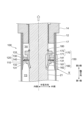
- FIG. 2 is an example of an enlarged view of part II in FIG.
- FIG. 3 is an example of a view of the seal member 120 as viewed from a first side in the axial direction.
- the second piston portion 100 includes an annular elastic member 110 having elasticity, and a seal member 120 that is arranged on the opposite side of the first piston portion 30 (in other words, the second side) with respect to the elastic member 110 in the axial direction of the rod 20 and can come into contact with the inner circumferential surface of the collar 17.
- the second piston portion 100 also includes a restricting member 150 that restricts the axial movement of the elastic member 110 and the seal member 120, and a clip 180 that has a circular cross-sectional shape and a C-shaped shape when viewed in the axial direction and restricts the axial movement of the restricting member 150.
- the elastic member 110 is, for example, a ring-shaped plate made of metal.
- the inner diameter of the elastic member 110 is equal to or larger than the diameter of the outer circumferential surface of the rod portion 21 of the rod 20, and the outer diameter of the elastic member 110 is smaller than the diameter of the inner circumferential surface of the collar 17.
- the sealing member 120 is a cylindrical member made of, for example, metal or resin. More specifically, the sealing member 120 has a cylindrical base 130 and a protruding portion 140 that protrudes in an annular shape from an outer periphery of an opposing surface 131 of the base 130 that faces the elastic member 110 toward the elastic member 110 (in other words, the first side).
- the inner diameter of the base 130 is larger than the diameter of the outer peripheral surface of the rod portion 21 of the rod 20, and the outer diameter of the base 130 is equal to the diameter of the inner peripheral surface of the collar 17.
- the base 130 has a plurality of recesses 132 (ten in the example shown in FIG. 3) formed in the circumferential direction in a region inside the protrusions 140, which are recessed from the opposing surface 131 toward the opposite side to the elastic member 110 (in other words, the second side).
- the cross-sectional shape of the convex portion 140 when cut along a plane parallel to the axial direction is a rectangle with the radial direction being the long side and the axial direction being the short side.
- the inner peripheral surface of the convex portion 140 may be an inclined surface whose inner diameter increases toward the first side. This is because oil can flow more smoothly along the inclined surface.
- the convex portion 140 has a groove 141 formed therein, which extends in the radial direction so as to connect the inner portion and the outer portion of the convex portion 140.
- the groove 141 is formed at a position that does not overlap with the recess 132 in the circumferential direction.
- one groove 141 is formed, but the number of grooves 141 is not limited to one and may be multiple.
- the total cross-sectional area of the one or multiple grooves 141 when cut in a plane perpendicular to the axial direction is smaller than the total cross-sectional area of the multiple recesses 132.
- the restricting member 150 has a first member 160 and a second member 170 arranged side by side in the axial direction.
- the restricting member 150 can be, for example, a member made of a metal or a resin.
- the first member 160 has a cylindrical portion 161 and a protruding portion 162 that protrudes inward from a lower end of the cylindrical portion 161 .
- the inner diameter of the cylindrical portion 161 is equal to or larger than the diameter of the outer circumferential surface of the rod portion 21 of the rod 20.
- the outer diameter of the cylindrical portion 161 is smaller than the diameter of the inner circumferential surface of the collar 17 and larger than the inner diameters of the elastic member 110 and the seal member 120.
- the protrusion 162 protrudes from the lower end of the cylindrical portion 161 around the entire circumference in a direction inclined toward the axial direction.
- the tip of the protrusion 162 fits into the first groove 211 of the rod portion 21, so that the first member 160 is held by the rod 20 so as not to move relative to the rod 20.
- the second member 170 has a cylindrical first cylindrical portion 171 and a cylindrical second cylindrical portion 172 provided on the second side of the first cylindrical portion 171.
- the inner diameters of the first cylindrical portion 171 and the second cylindrical portion 172 are equal and are equal to or greater than the diameter of the outer circumferential surface of the rod portion 21.
- the outer diameter of the second cylindrical portion 172 is greater than the outer diameter of the first cylindrical portion 171.
- the outer diameter of the first cylindrical portion 171 is smaller than the inner diameter of the seal member 120.
- the outer diameter of the second cylindrical portion 172 is smaller than the diameter of the inner circumferential surface of the collar 17 and greater than the inner diameter of the seal member 120.
- the restricting member 150 is attached to the rod 20 with the inner periphery of the elastic member 110 sandwiched between the first member 160 and the second member 170. Then, the protrusion 162 of the first member 160 fits into the first groove 211 of the rod portion 21, so that the first member 160 is held by the rod 20 so as not to move relative to the rod 20, and the movement of the second member 170 towards the second side is restricted by the clip 180. As a result, the inner periphery of the elastic member 110 becomes the fixed end, and the outer periphery becomes the free end.
- FIG. 4 is an example of a cross-sectional view of the second piston portion 100 during the extension stroke in which the amount by which the rod 20 protrudes from the cylinder portion 10 (hereinafter sometimes referred to as the "protrusion amount") increases.
- FIG. 5 is an example of an enlarged view of a portion V in FIG.
- FIG. 6 is an example of a cross-sectional view of the second piston portion 100 during the extension stroke.
- the space within the collar 17 on the first side of the seal member 120 may be referred to as the "third chamber Y3,” and the space within the collar 17 on the second side of the seal member 120 may be referred to as the "fourth chamber Y4.”
- the fourth chamber Y4 is the high-pressure chamber described above.
- part of the oil in the fourth chamber Y4 flows through the recess 132 of the seal member 120 into the fifth chamber Y5, which is a space surrounded by the opposing surface 131 of the seal member 120, the inner surface of the protrusion 140, and the elastic member 110.
- part of the oil in the fifth chamber Y5 flows out into the third chamber Y3 through a groove 141 formed in the protrusion 140 of the seal member 120.
- the groove 141 functions as an orifice that allows oil to flow from the fourth chamber Y4 to the third chamber Y3.
- the flow path area (in other words, the cross-sectional area cut along a plane perpendicular to the axial direction) in the recess 132 and groove 141 is set as follows. In other words, when the opposing surface 131 and the convex portion 140 come into contact with the elastic member 110, the total flow path area formed by the groove 141 and the elastic member 110 is smaller than the total flow path area formed by the recess 132 and the elastic member 110.
- FIG. 7 is an example of a cross-sectional view of the second piston portion 100 during the compression stroke when the amount of protrusion of the rod 20 decreases. 7, during the compression stroke in which the amount of protrusion of the rod 20 from the cylinder portion 10 decreases, if the force acting on the first side portion of the seal member 120 becomes greater than the force acting on the second side end face 133 of the seal member 120, the seal member 120 moves to the second side and hits the second cylindrical portion 172. When the seal member 120 moves to the first side beyond the collar 17, oil flows through the outside of the seal member 120, so that the pressures in the spaces on the first side and the second side of the seal member 120 become equal.
- the shock absorber 2 includes the rod 20, a part of which is inserted into the cylindrical cylinder 11, the first piston portion 30 fixed to the rod 20 and defining a space within the cylinder 11, and the cylindrical collar 17 arranged on the rod 20 side (in other words, the second side) of the first piston portion 30 within the cylinder 11.
- the shock absorber 2 also includes the second piston portion 100 fixed to the rod 20 coaxially with the first piston portion 30 and capable of entering the collar 17 to form a fourth chamber Y4 in the space within the collar 17 as an example of a high-pressure chamber having a higher pressure than the first piston portion side.
- the second piston portion 100 includes an annular elastic member 110 having elasticity, a seal member 120 arranged on the opposite side of the first piston portion 30 with respect to the elastic member 110 in the axial direction of the rod 20 and capable of contacting the inner circumferential surface of the collar 17, and a restricting member 150 that restricts the axial movement of the elastic member 110 and the seal member 120.
- the seal member 120 has a cylindrical base 130 and a protrusion 140 that protrudes from the outer periphery of an opposing surface 131 of the base 130 that faces the elastic member 110 toward the elastic member 110 in an annular shape and can contact the outer periphery of the elastic member 110.
- the base 130 has a recess 132 formed on the inside of the protrusion 140, recessed from the opposing surface 131 to the opposite side to the elastic member 110, and the protrusion 140 has a groove 141 formed in at least a portion of the circumferential direction that connects the inside and outside.
- the damping force during the extension stroke it is desirable for the damping force during the extension stroke to be high. For example, by suppressing the lift of the inner wheel during cornering, the occurrence of roll is suppressed, which contributes to improving ride comfort.
- the second piston portion 100 forms a high-pressure chamber (in other words, the fourth chamber Y4) within the collar 17 during the extension stroke, so that the damping force can be increased compared to a configuration that does not have the second piston portion 100, for example.
- the groove 141 functions as an orifice that allows oil to flow from the fourth chamber Y4 to the third chamber Y3, preventing the damping force from becoming too high.
- these damping forces can be set by changing the flow area of the groove 141 and the recess 132, so that the damping force characteristics can be set with a high degree of freedom. Also, by configuring the second piston portion 100 with the elastic member 110, the seal member 120, and the restricting member 150, a shock absorber 2 that achieves the above effects can be realized at low cost.
- the restricting member 150 has a first member 160 and a second member 170 arranged side by side in the axial direction, and the elastic member 110 is sandwiched between the first member 160 and the second member 170. This makes it possible to suppress the axial movement of the elastic member 110, and to quickly switch from one of the compression stroke and the expansion stroke to the other.
- the elastic member 110 does not have to be sandwiched between the first member 160 and the second member 170.
- the inner diameter of the elastic member 110 may be smaller than the inner diameter of the sealing member 120 and larger than the inner diameter of the first cylindrical portion 171 of the second member 170, so that the elastic member 110 is movable between the first member 160 and the sealing member 120.
- FIG. 8 is a diagram showing an example of a schematic configuration of the second piston portion 200 according to the second embodiment.
- the second piston portion 200 according to the second embodiment is different from the second piston portion 100 according to the first embodiment in that it has a seal member 220 that corresponds to the seal member 120.
- the following describes the differences from the first embodiment.
- the same reference numerals are used for the same parts in the first and second embodiments, and detailed descriptions thereof will be omitted.
- Sealing member 220 differs from sealing member 120 in that it has a symmetrical shape with respect to a plane perpendicular to the axial direction.
- sealing member 220 has a base 230 that corresponds to base 130 in the first embodiment, a protruding portion 140, and a protruding portion 240 that protrudes in an annular shape from the outer periphery of the end face 233 on the second side of base 230 to the second side.
- the convex portion 240 is symmetrical to the convex portion 140 with respect to a plane perpendicular to the axial direction, and a groove 241 is formed extending in the radial direction so as to connect the inner portion of the convex portion 240 with the outer portion.
- the base 230 differs from the base 130 according to the first embodiment in that multiple (e.g., 10) recesses 232 recessed from the end face 233 to the first side are formed in the circumferential direction in an area inside the protrusion 240.
- the recesses 232 are symmetrical to the recesses 132 with respect to a plane perpendicular to the axial direction.
- the base 230 is symmetrical with respect to a plane perpendicular to the axial direction.
- the second piston portion 200 according to the second embodiment can achieve the same effects as those achieved by the second piston portion 100 according to the first embodiment described above.
- the seal member 220 has a symmetrical shape with respect to a plane perpendicular to the axial direction, so that the seal member 220 can be assembled without having to worry about the orientation of the seal member 220. As a result, the second piston portion 200 can improve ease of assembly.
- FIG. 9 is a diagram showing an example of a state of the second piston portion 200 during a compression stroke in which the amount of protrusion of the rod 20 decreases.
- the end face 233 of the sealing member 220 abuts against the second cylindrical portion 172, and oil flows from the third chamber Y3 to the fourth chamber Y4 through the recess 232 of the sealing member 220, thereby making it possible to smoothly switch from the extension stroke to the compression stroke.
- FIG. 10 is a diagram showing an example of a schematic configuration of a second piston portion 300 according to the third embodiment.
- FIG. 11 is an example of a view of an elastic member 310 according to the third embodiment as viewed in the axial direction.
- the second piston portion 300 according to the third embodiment is different from the second piston portion 100 according to the first embodiment in that it has an elastic member 310 corresponding to the elastic member 110 and a regulating member 350 corresponding to the regulating member 150.
- the same reference numerals are used for the same parts in the first and third embodiments, and detailed descriptions thereof will be omitted.
- the restricting member 350 has a first member 160 and a second member 370 equivalent to the second member 170.
- the second member 370 differs from the second member 170 according to the first embodiment in that a recess 373 recessed from the outer circumferential surface is formed around the entire circumference at the end of the first side.
- the axial size of the recess 373 is equal to or greater than the thickness of the elastic member 310.
- the second member 370 is arranged such that the end face on the first side can come into contact with the end face on the second side of the first member 160.
- the elastic member 310 is not sandwiched between the first member 160 and the second member 370.
- the elastic member 310 has multiple protrusions 311 (eight in the example shown in FIG. 11) in the circumferential direction that protrude from the inner end toward the center, as compared to the elastic member 110 according to the first embodiment.
- the multiple protrusions 311 can be, for example, formed at equal intervals in the circumferential direction.
- the radius of an imaginary circle formed by the tips of the multiple protrusions 311 is equal to or less than the diameter of the outer circumferential surface 374 of the portion of the second member 370 where the recess 373 is formed.
- the elastic member 310 is fixed to the regulating member 350 by the multiple protrusions 311 gripping the outer circumferential surface 374.
- the second piston portion 300 according to the third embodiment can also achieve the same effects as those achieved by the second piston portion 100 according to the first embodiment described above.
- the elastic member 310 has a protrusion 311 that grips the outer peripheral surface 374 of the regulating member 350 and fixes the elastic member 310 to the regulating member 350. This allows the elastic member 310 and the regulating member 350 to be integrated in advance when assembling the second piston portion 300, so that the second piston portion 300 can improve ease of assembly.
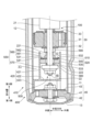
- FIG. 12 is a diagram showing an example of a schematic configuration of a shock absorber 400 according to the fourth embodiment.
- the shock absorber 400 according to the fourth embodiment differs from the shock absorber 2 according to the first embodiment in that it includes a cylinder portion 410 equivalent to the cylinder portion 10, and a third piston portion 500 that can prevent the pressure in the cylinder 11 from becoming too high during the compression stroke.
- the differences from the first embodiment will be described below.
- the same reference numerals are used for the same parts in the first and fourth embodiments, and detailed descriptions thereof will be omitted.
- the cylinder section 410 differs from the cylinder section 10 in that it further has a second collar 420 at the end on the first side inside the cylinder 11.
- the second collar 420 is tubular with a bottom and has a cylindrical cylindrical section 421 and a blocking section 422 that blocks the opening on the first side of the cylindrical section 421.
- the second collar 420 also has a number of legs 423 provided on the first side of the blocking section 422.
- the cylindrical portion 421 is capable of housing the third piston portion 500 therein, and forms a gap between the cylindrical portion 421 and the cylinder 11 .
- the leg portion 423 is a portion that extends in the radial direction and to the first side from an outer portion of the blocking portion 422. The portion extending to the first side has an arc shape when viewed in the axial direction. A plurality of the leg portions 423 (e.g., three) are provided at equal intervals in the circumferential direction.
- the second collar 420 is fixed to the end portion on the first side inside the cylinder 11 by joining the leg portion 423 to the cylinder 11 by, for example, welding or adhesive.
- the leg portion 423 is located outside the valve 43, and the blocking portion 422 is located on the second side of the bottom valve 40. Since it is sufficient for the second collar 420 to accommodate the third piston portion 500, the thickness of each portion may be the minimum required.
- the third piston portion 500 includes an annular elastic member 510 having elasticity, and a sealing member 520 that is arranged on the opposite side of the elastic member 510 from the first piston portion 30 in the axial direction (in other words, the first side) and can contact the inner circumferential surface of the cylindrical portion 421 of the second collar 420.
- the third piston portion 500 also includes a first restricting member 550 that restricts the axial movement of the elastic member 510 and the sealing member 520.
- the third piston portion 500 also includes a second restricting member 590 that is annular and restricts the axial movement of the first piston portion 30.
- the elastic member 510 is, for example, a ring-shaped plate made of a metal material.
- the inner diameter of the elastic member 510 is equal to or larger than the diameter of the outer circumferential surface of the lower attachment portion 22 of the rod 20, and the outer diameter of the elastic member 510 is smaller than the diameter of the inner circumferential surface of the cylindrical portion 421 of the second collar 420.
- the sealing member 520 is a cylindrical member made of, for example, metal or resin. More specifically, the sealing member 520 has a cylindrical base 530 and a protruding portion 540 that protrudes in an annular shape from the outer periphery of an opposing surface 531 of the base 530 that faces the elastic member 510 toward the elastic member 510 (in other words, the second side).
- the outer diameter of the base 530 is approximately equal to the diameter of the inner peripheral surface of the cylindrical portion 421 of the second collar 420.
- the base 530 has a plurality of (e.g., 10) recesses 532 formed in the circumferential direction at a portion inside the protrusion 540, the recesses 532 being recessed from the opposing surface 531 toward the opposite side to the elastic member 510 (in other words, the first side).
- the cross-sectional shape of the convex portion 540 when cut along a plane parallel to the axial direction is a rectangle with the radial direction being the long side and the axial direction being the short side.
- the inner peripheral surface of the convex portion 540 may be an inclined surface whose inner diameter increases toward the second side. This is because oil can flow more smoothly along the inclined surface.
- the convex portion 540 has a groove 541 formed therein, which extends in the radial direction so as to connect the inner portion of the convex portion 540 with the outer portion.
- the groove 541 is formed at a position that does not overlap with the recessed portion 532 in the circumferential direction.
- the total cross-sectional area of the one or multiple grooves 541 when cut in a plane perpendicular to the axial direction is smaller than the total cross-sectional area of the multiple recessed portions 532.
- the first restricting member 550 has a first member 560 and a second member 570 arranged side by side in the axial direction.
- the first restricting member 550 can be, for example, a member made of metal or resin.
- the first member 560 has a cylindrical portion 561 and a protruding portion 562 that protrudes inward from an upper end portion of the cylindrical portion 561 .
- the inner diameter of the cylindrical portion 561 is equal to or larger than the diameter of the outer circumferential surface of the lower mounting portion 22 of the rod 20.
- the outer diameter of the cylindrical portion 561 is smaller than the outer diameter of the elastic member 510 and larger than the inner diameters of the elastic member 510 and the seal member 520.
- the protrusion 562 protrudes from the upper end of the cylindrical portion 561 around the entire circumference in a direction inclined toward the axial direction.
- the tip of the protrusion 562 fits into the first groove 221 of the lower mounting portion 22, thereby holding the first member 560 to the rod 20 so that it does not move relative to the rod 20.
- the second member 570 is an annular member.
- the inner diameter of the second member 570 is equal to or greater than the diameter of the outer peripheral surface of the lower mounting portion 22.
- the outer diameter of the second member 570 is smaller than the diameter of the inner peripheral surface of the cylindrical portion 421 of the second collar 420.
- the movement of the second member 570 toward the second side is restricted by means of, for example, press-fitting. Note that the movement of the second member 570 toward the second side may be restricted by a clip 580 fitted into a second groove 222 formed on the outer peripheral surface of the lower mounting portion 22, as shown in FIG. 12.
- FIG. 13 is an example of a cross-sectional view of the third piston portion 500 during the compression stroke.
- the seal member 520 enters the second collar 420 and contacts the inner circumferential surface of the cylindrical portion 421 of the second collar 420.
- a high-pressure chamber is formed in which the pressure is higher than the space in the first chamber Y1 on the first piston portion 30 side (in other words, the second side) of the seal member 520.
- the space in the cylindrical portion 421 on the second side of the seal member 520 may be referred to as the "seventh chamber Y7," and the space in the cylindrical portion 421 on the first side of the seal member 520 may be referred to as the "eighth chamber Y8.”
- the eighth chamber Y8 is the high-pressure chamber described above.
- the sealing member 520 bends the outer periphery of the elastic member 510.
- the opposing surface 531 of the sealing member 520 comes into contact with the elastic member 510, and the elastic member 510 is sandwiched between the sealing member 520 and the cylindrical portion 561 of the first member 560.
- the flow path area (in other words, the cross-sectional area cut along a plane perpendicular to the axial direction) in the concave portion 532 and the groove 541 is set as follows.
- the total flow path area formed by the groove 541 and the elastic member 510 is smaller than the total flow path area formed by the concave portion 532 and the elastic member 510.
- the third piston portion 500 forms a high-pressure chamber (in other words, the eighth chamber Y8) within the cylindrical portion 421 of the second collar 420, so that the damping force can be increased more than, for example, a configuration that does not include the third piston portion 500.
- the groove 541 functions as an orifice that allows oil to flow from the eighth chamber Y8 to the seventh chamber Y7, so that the damping force can be prevented from becoming too high.
- these damping forces can be set by changing the flow area of the groove 541 and the recess 532, so that the damping force characteristics can be set with a high degree of freedom. Also, by configuring the third piston portion 500 with the elastic member 510, the seal member 520, and the first restricting member 550, a shock absorber 400 that achieves the above effects can be realized at low cost.
Landscapes
- Engineering & Computer Science (AREA)
- General Engineering & Computer Science (AREA)
- Mechanical Engineering (AREA)
- Fluid-Damping Devices (AREA)
Priority Applications (3)
| Application Number | Priority Date | Filing Date | Title |
|---|---|---|---|
| JP2025518071A JPWO2024228248A1 (https=) | 2023-05-02 | 2023-05-02 | |
| DE112023005608.0T DE112023005608T5 (de) | 2023-05-02 | 2023-05-02 | Stossdämpfungsvorrichtung und federungsvorrichtung |
| PCT/JP2023/017106 WO2024228248A1 (ja) | 2023-05-02 | 2023-05-02 | 緩衝装置、懸架装置 |
Applications Claiming Priority (1)
| Application Number | Priority Date | Filing Date | Title |
|---|---|---|---|
| PCT/JP2023/017106 WO2024228248A1 (ja) | 2023-05-02 | 2023-05-02 | 緩衝装置、懸架装置 |
Publications (1)
| Publication Number | Publication Date |
|---|---|
| WO2024228248A1 true WO2024228248A1 (ja) | 2024-11-07 |
Family
ID=93332980
Family Applications (1)
| Application Number | Title | Priority Date | Filing Date |
|---|---|---|---|
| PCT/JP2023/017106 Ceased WO2024228248A1 (ja) | 2023-05-02 | 2023-05-02 | 緩衝装置、懸架装置 |
Country Status (3)
| Country | Link |
|---|---|
| JP (1) | JPWO2024228248A1 (https=) |
| DE (1) | DE112023005608T5 (https=) |
| WO (1) | WO2024228248A1 (https=) |
Citations (6)
| Publication number | Priority date | Publication date | Assignee | Title |
|---|---|---|---|---|
| JPS62196432A (ja) * | 1986-01-31 | 1987-08-29 | Kayaba Ind Co Ltd | シヨツクアブソ−バ |
| JPH10184760A (ja) * | 1996-11-12 | 1998-07-14 | Tenneco Automot Inc | ショックアブソーバ |
| US20160223045A1 (en) * | 2015-02-03 | 2016-08-04 | Tenneco Automotive Operating Company Inc. | Secondary dampening assembly for shock absorber |
| JP2018105425A (ja) * | 2016-12-27 | 2018-07-05 | 日立オートモティブシステムズ株式会社 | シリンダ装置 |
| JP2019184033A (ja) * | 2018-04-17 | 2019-10-24 | Kyb株式会社 | 緩衝器 |
| EP3845771A1 (en) * | 2019-12-27 | 2021-07-07 | BeijingWest Industries Co. Ltd. | Hydraulic damper assembly including an anti-noise member |
-
2023
- 2023-05-02 DE DE112023005608.0T patent/DE112023005608T5/de active Pending
- 2023-05-02 WO PCT/JP2023/017106 patent/WO2024228248A1/ja not_active Ceased
- 2023-05-02 JP JP2025518071A patent/JPWO2024228248A1/ja active Pending
Patent Citations (6)
| Publication number | Priority date | Publication date | Assignee | Title |
|---|---|---|---|---|
| JPS62196432A (ja) * | 1986-01-31 | 1987-08-29 | Kayaba Ind Co Ltd | シヨツクアブソ−バ |
| JPH10184760A (ja) * | 1996-11-12 | 1998-07-14 | Tenneco Automot Inc | ショックアブソーバ |
| US20160223045A1 (en) * | 2015-02-03 | 2016-08-04 | Tenneco Automotive Operating Company Inc. | Secondary dampening assembly for shock absorber |
| JP2018105425A (ja) * | 2016-12-27 | 2018-07-05 | 日立オートモティブシステムズ株式会社 | シリンダ装置 |
| JP2019184033A (ja) * | 2018-04-17 | 2019-10-24 | Kyb株式会社 | 緩衝器 |
| EP3845771A1 (en) * | 2019-12-27 | 2021-07-07 | BeijingWest Industries Co. Ltd. | Hydraulic damper assembly including an anti-noise member |
Also Published As
| Publication number | Publication date |
|---|---|
| JPWO2024228248A1 (https=) | 2024-11-07 |
| DE112023005608T5 (de) | 2025-11-06 |
Similar Documents
| Publication | Publication Date | Title |
|---|---|---|
| JP5519821B1 (ja) | 圧力緩衝装置 | |
| US9592716B2 (en) | Pressure damping device | |
| US10837514B2 (en) | Valve structure of shock absorber | |
| WO2024228248A1 (ja) | 緩衝装置、懸架装置 | |
| JP7199513B2 (ja) | 緩衝器 | |
| JP7710032B2 (ja) | 緩衝器 | |
| US20240375472A1 (en) | Damper oil seal cap with seal protection feature | |
| CN114517819B (zh) | 单管阻尼器组件和用于其的液压回弹止动组件 | |
| JP2023020610A (ja) | 油圧緩衝装置、懸架装置 | |
| JP7151020B1 (ja) | 緩衝装置、懸架装置 | |
| JP2025014216A (ja) | 減衰力発生装置、懸架装置 | |
| JP7450057B2 (ja) | 制御弁装置 | |
| JP7515441B2 (ja) | 緩衝器 | |
| US20260070385A1 (en) | Base Valve With Open Bleed Tuning Capabilities | |
| WO2021153378A1 (ja) | 緩衝器 | |
| JP7584366B2 (ja) | 溶接部材および緩衝器 | |
| JP2025095382A (ja) | 緩衝器及びリバウンドスプリング | |
| JP2025014218A (ja) | 緩衝装置、懸架装置 | |
| JP2024051645A (ja) | 懸架装置 | |
| WO2024154337A1 (ja) | 緩衝装置、懸架装置 | |
| JP2025142955A (ja) | 緩衝装置、懸架装置 | |
| JP6302148B1 (ja) | 圧力緩衝装置 | |
| WO2025022892A1 (ja) | 緩衝器 | |
| JP2024155262A (ja) | リバウンドスプリングユニット、懸架装置 | |
| WO2024201696A1 (ja) | 緩衝装置、懸架装置 |
Legal Events
| Date | Code | Title | Description |
|---|---|---|---|
| 121 | Ep: the epo has been informed by wipo that ep was designated in this application |
Ref document number: 23935761 Country of ref document: EP Kind code of ref document: A1 |
|
| WWE | Wipo information: entry into national phase |
Ref document number: 112023005608 Country of ref document: DE |
|
| ENP | Entry into the national phase |
Ref document number: 2025518071 Country of ref document: JP Kind code of ref document: A |
|
| WWE | Wipo information: entry into national phase |
Ref document number: 2025518071 Country of ref document: JP |