WO2024224460A1 - 冷却器 - Google Patents
冷却器 Download PDFInfo
- Publication number
- WO2024224460A1 WO2024224460A1 PCT/JP2023/016172 JP2023016172W WO2024224460A1 WO 2024224460 A1 WO2024224460 A1 WO 2024224460A1 JP 2023016172 W JP2023016172 W JP 2023016172W WO 2024224460 A1 WO2024224460 A1 WO 2024224460A1
- Authority
- WO
- WIPO (PCT)
- Prior art keywords
- fin
- layer
- flow path
- inlet
- outlet
- Prior art date
- Legal status (The legal status is an assumption and is not a legal conclusion. Google has not performed a legal analysis and makes no representation as to the accuracy of the status listed.)
- Ceased
Links
Images










Classifications
-
- H—ELECTRICITY
- H10—SEMICONDUCTOR DEVICES; ELECTRIC SOLID-STATE DEVICES NOT OTHERWISE PROVIDED FOR
- H10W—GENERIC PACKAGES, INTERCONNECTIONS, CONNECTORS OR OTHER CONSTRUCTIONAL DETAILS OF DEVICES COVERED BY CLASS H10
- H10W40/00—Arrangements for thermal protection or thermal control
- H10W40/40—Arrangements for thermal protection or thermal control involving heat exchange by flowing fluids
- H10W40/47—Arrangements for thermal protection or thermal control involving heat exchange by flowing fluids by flowing liquids, e.g. forced water cooling
Definitions
- This disclosure relates to a cooler that cools an element using a refrigerant circulated by a pump.
- Patent Document 1 discloses a cooler for cooling a conventional semiconductor power device.
- the cooler described in Patent Document 1 includes a substrate assembly in which a manifold layer, a channel layer, a ceramic layer, and a metal layer are stacked and joined in order, and a plenum housing having an inlet port and an outlet port.
- the manifold layer branches the cooling water, which is a refrigerant from the inlet port of the plenum housing, into an inlet manifold, which is a plurality of flow paths, and supplies it to the channel layer.
- the manifold layer also receives the cooling water that has passed through the channel layer in an outlet manifold, which is a plurality of flow paths, and merges it into the outlet port of the plenum housing.
- inlet manifolds and outlet manifolds extending in a first direction are alternately provided at a set interval in the second direction.
- the channel layer is a layer that supplies the cooling water from the manifold layer to channels extending in the second direction and returns the cooling water that has flowed through the channels to the manifold layer.
- the channel layer has a plurality of channels extending in the second direction at a set interval in the first direction on the side of the joint surface with the manifold layer.
- the ceramic layer is made of a material with high thermal conductivity.
- the metal layer is connected to the semiconductor power device to be cooled.
- the temperature distribution can be adjusted by changing the heat generation distribution through pattern design inside the element or by adjusting the amount of current.
- a design that takes into account such temperature distribution adjustment is not easy.
- the temperature distribution is concentric and small.
- the direction in which the cooling water flows in the channel layer that contacts the ceramic layer is one direction, the direction of the channel that is formed to extend in the second direction. For this reason, there was a problem in that the temperature distribution was not concentric, and the temperature changed significantly in the direction of the cooling water flow.
- the present disclosure has been made in consideration of the above, and aims to obtain a cooler that can bring the temperature distribution generated by the cooler closer to a concentric shape and reduce the temperature distribution inside the element compared to conventional coolers.
- the cooler according to the present disclosure is a cooler that is bonded to an element and cools the element, and includes a base layer to which the element is bonded, a fin forming layer having a fin arrangement area in which a plurality of fins connected to the base layer are arranged, and an opening forming layer that is connected to the fin forming layer and has a plurality of fin inlets and a plurality of fin outlets for flowing coolant to the fin arrangement area.
- the multiple fin inlets are connected via inlet flow paths to an inlet through which the coolant of the cooler flows in.
- the multiple fin outlets are connected via outlet flow paths to an outlet through which the coolant of the cooler flows out.
- the multiple fin inlets and multiple fin outlets are arranged alternately and in parallel in a direction radially away from a point within an area in which the shape of the element is projected onto the opening forming layer.
- the cooler disclosed herein has the effect of making the temperature distribution generated by the cooler closer to a concentric shape, and also reducing the temperature distribution inside the element compared to conventional coolers.
- FIG. 1 is a cross-sectional view illustrating a schematic example of a configuration of a cooler according to a first embodiment.
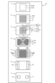
- FIG. 2 is an exploded top view showing the configuration of each layer of the cooler according to the first embodiment.
- FIG. 1 is a diagram for explaining an example of a flow of a refrigerant in a cooler according to the first embodiment;
- FIG. 1 is a diagram showing an example of a flow of a refrigerant in an opening forming layer of a cooler according to a first embodiment;
- FIG. 1 is a diagram showing an example of a relationship between an opening forming layer constituting a cooler according to a first embodiment and an element arrangement region; Enlarged top view of part of the opening formation layer FIG.
- FIG. 11 is a top view showing another example of the configuration of the opening forming layer constituting the cooler according to the first embodiment;
- FIG. 11 is a top view showing another example of the configuration of the opening forming layer constituting the cooler according to the first embodiment;
- FIG. 11 is a top view showing another example of the configuration of the opening forming layer constituting the cooler according to the first embodiment;
- FIG. 11 is a top view showing another example of the configuration of the opening forming layer constituting the cooler according to the first embodiment;
- FIG. 11 is a top view showing another example of the configuration of the opening forming layer constituting the cooler according to the first embodiment;
- FIG. 11 is a top view showing another example of the configuration of the opening forming layer constituting the cooler according to the first embodiment;
- FIG. 11 is a top view showing another example of the configuration of the opening forming layer constituting the cooler according to the first embodiment;
- FIG. 11 is a top view showing another example of the configuration of the opening forming layer constituting the cooler according to the first embodiment;
- FIG. 1 is a partially enlarged top view showing an example of a configuration of a fin forming layer that constitutes a cooler according to a first embodiment
- FIG. 13 is a top view showing another example of the configuration of the fin forming layer constituting the cooler according to the first embodiment
- FIG. 15 is an enlarged top view of a portion of the fin arrangement region of the fin forming layer of FIG.
- FIG. 15 is a top view showing an example of a configuration of an opening forming layer corresponding to the fin forming layer of FIG.
- FIG. 1 is a partially enlarged top view showing an example of a configuration of a fin forming layer that constitutes a cooler according to a first embodiment
- FIG. 13 is a top view showing another example of the configuration of the fin forming layer constituting the cooler according to the first embodiment
- FIG. 15 is an enlarged top view of a portion of the fin arrangement region of the fin forming layer of FIG.
- FIG. 15 is a top view showing an example of a configuration of an opening forming layer
- FIG. 11 is a cross-sectional view showing a schematic example of a configuration of a cooler according to a second embodiment.
- FIG. 13 is a top view showing an example of a configuration of a flow path forming layer that configures a cooler according to a second embodiment.
- FIG. 1 is a diagram showing an example of a state in which an opening forming layer and a flow path forming layer are overlapped.
- FIG. 13 is a cross-sectional view showing a schematic example of a configuration of a cooler according to a third embodiment.
- FIG. 11 is a top view showing an example of a configuration of a flow path connection layer that configures a cooler according to embodiment 3.
- FIG. 13 is a top view showing an example of the configuration of a flow path distribution layer constituting a cooler according to embodiment 3.
- FIG. 11 is a top view showing an example of the configuration of an inlet/outlet arrangement layer constituting a cooler according to embodiment 3.
- FIG. 11 is a top view showing an example of a configuration of a flow path connection layer that configures a cooler according to embodiment 3.
- FIG. 1 is a cross-sectional view showing a schematic example of the configuration of a cooler according to the first embodiment.
- An element 100 to be cooled is bonded to the cooler 10 via a thermally conductive layer 101 having insulating properties.
- the element 100 is an element that generates heat due to the operation of a laser element or the like.
- the thermally conductive layer 101 is a layer that transfers heat from the element 100 to the cooler 10, and is a material having insulating properties and high thermal conductivity that easily transfers heat.
- the thermally conductive layer 101 and the element 100 are bonded with a bonding material.
- Examples of the thermally conductive layer 101 are aluminum nitride (AlN), aluminum oxide (Al 2 O 3 ), ceramics such as AlSiC, and diamond.
- the thermally conductive layer 101 also serves to prevent the element 100 from being destroyed by stress generated during bonding due to the difference in thermal expansion coefficient between the element 100 and the cooler 10.
- the element 100 is not insulated by the thermally conductive layer 101, CuW, CuMo, etc. may be used to adjust the stress generated during bonding due to the difference in thermal expansion coefficient.
- the element 100 may be directly bonded onto the cooler 10 via a bonding material without the thermal conduction layer 101.
- the current flow through the element 100 is performed by connecting a pattern made of a thin film such as a copper (Cu) film formed on the thermal conduction layer 101 to the electrodes around the element 100 via wire bonds or the like.
- the thermal conduction layer 101 is bonded to the cooler 10 via a bonding material.
- the cooler 10 is a device that is bonded to the element 100 and cools the element 100 using a refrigerant circulated by a pump (not shown).
- the cooler 10 according to the first embodiment is roughly composed of seven metal layers. That is, the cooler 10 has, in order from the side where the element 100 is arranged, a base layer 1, a fin forming layer 2, an opening forming layer 3, a flow path forming layer 4, a flow path forming layer 5, a flow path connection layer 6, and an inlet/outlet arrangement layer 7.
- Each of these layers is composed of a metal layer.
- metals with good thermal conductivity such as Cu and Al (aluminum) can be used.
- each layer of the cooler 10 is rectangular.
- the cooler 10 is divided into multiple layers with attention paid to the function of each metal layer, and the cooler 10 is not necessarily composed of physically separated metal layers bonded together. Also, one layer may be composed of multiple layers that are physically separated.
- the stacking direction of each metal layer is the Z-axis direction. Additionally, two positions in the Z-axis direction are expressed relative to each other using up and down.
- FIG. 2 is a top view showing an exploded configuration of each layer of the cooler according to embodiment 1.
- the center of the projection area which is the area where the element 100 is arranged projected onto the upper surface of the opening formation layer 3 is taken as the origin
- the X-axis is taken in a direction that passes through the origin and is parallel to the long side of the rectangular opening formation layer 3
- the Y-axis is taken in a direction that passes through the origin and is parallel to the short side of the rectangular opening formation layer 3.
- the X-axis, Y-axis, and Z-axis are perpendicular to each other. However, this is just an example, and the X-axis and Y-axis can be set arbitrarily.
- the base layer 1 is a metal layer on which the element 100 is placed either directly or via the thermal conduction layer 101, and serves as a base plate.
- the base layer 1 is a flat metal layer.
- region R100 indicates the element placement region where the element 100 is placed
- region R101 indicates the thermal conduction layer placement region where the thermal conduction layer 101 is placed.
- the element placement region R100 is such that the center of the element 100 is located at the center of the XY plane of the base layer 1.
- the thermal conduction layer placement region R101 includes the element placement region R100 and is larger than the element placement region R100.
- the fin formation layer 2 is a metal layer disposed on the lower surface of the base layer 1 and connected to the base layer 1.
- the fin formation layer 2 has a plurality of fins 21 that are connected to the base layer 1 and improve cooling performance in an area including at least the area where the element arrangement area R100 is projected.
- the area where the fins 21 are formed is called the fin arrangement area R20.
- a plurality of fins 21 are periodically arranged in a two-dimensional plane. Between the fins 21, grooves 22 are formed as a flow path for the coolant.
- An example of the fin 21 is a pin fin that extends in the Z-axis direction and has one end connected to the base layer 1.
- a groove 22 is formed as an opening with the pin fin as a side wall.
- the groove 22 on the lower surface of the metal layer that constitutes the fin formation layer 2 is an opening to the fin arrangement area R20 in the Z-axis direction.
- the area of the fin formation layer 2 other than the fin arrangement area R20 is plate-shaped.
- the base layer 1 and the fin forming layer 2 can be produced by various production methods.
- the base layer 1 and the fin forming layer 2 can be integrally formed by forming the groove 22 by etching a single metal layer. Specifically, a mask is formed in the area other than the fin arrangement region R20 on the bottom surface of the single metal layer and in the pin fin formation position of the fin arrangement region R20. Then, the bottom surface of the metal layer on which the mask is formed is etched to a specified depth to form the groove 22 in the area where the mask is not formed. That is, in the fin arrangement region R20, the groove 22 is formed in the position where the mask is not formed, and the position where the mask is formed is left. This remaining part becomes a pin fin extending in the Z-axis direction.
- the base layer 1 and the fin forming layer 2 are produced from a single metal block, although they are illustrated as two layers in FIG. 1 and FIG. 2 for the purpose of explanation.
- producing the base layer 1 and the fin-forming layer 2 by etching is just one example, and they can also be produced by other methods.
- the base layer 1 and the fin-forming layer 2 can be produced by mold casting, or can be formed by cutting from a single metal member. It is also possible to produce them by stacking metal layers, as described below.
- the opening forming layer 3 is a metal layer having openings that are fin inlets 31 and fin outlets 32 for flowing coolant into the fin arrangement region R20.
- the opening forming layer 3 has, in an area including at least the area where the element arrangement region R100 is projected, a fin inlet 31 that supplies coolant to the fin arrangement region R20 and a fin outlet 32 that discharges coolant from the fin arrangement region R20.
- the fin inlets 31 and fin outlets 32 that are openings are alternately and parallelly arranged in a direction radially away from a point in the area where the element arrangement region R100 is projected. In this example, the point in the area where the element arrangement region R100 is projected is the origin.
- the fin inlets 31 and fin outlets 32 penetrate the metal layer in the Z-axis direction.
- the fin inlets 31 and fin outlets 32 are formed by connecting the ends of a plurality of openings that extend in different directions.
- the fin inlet 31 and the fin outlet 32 are formed by an opening in which an opening extending in the X-axis direction and an opening extending in the Y-axis direction are connected at their ends.
- the X-axis direction is an example of a first direction
- the Y-axis direction is an example of a second direction.
- the detailed structure of the openings in the opening formation layer 3 will be described later.
- the opening formation layer 3 is joined to the fin formation layer 2 on its upper surface.
- the flow path forming layer 4 is a metal layer having a flow path that guides the refrigerant flowing in from the flow path forming layer 5 to a specified opening in the opening forming layer 3, and guides the refrigerant discharged from the specified opening in the opening forming layer 3 to the flow path forming layer 5.
- the flow path forming layer 4 has a refrigerant inlet flow path 41 that forms part of the flow path that sends the refrigerant to the fin arrangement region R20, and a refrigerant outlet flow path 42 that forms part of the flow path that discharges the refrigerant from the fin arrangement region R20.
- the refrigerant inlet flow path 41 and the refrigerant outlet flow path 42 penetrate the metal layer in the Z-axis direction.
- the flow path forming layer 4 is joined to the opening forming layer 3 on the upper surface.
- the flow path forming layer 5 is a metal layer having a flow path that guides the refrigerant flowing in from the flow path connection layer 6 to the refrigerant inflow flow path 41 of the flow path forming layer 4, and guides the refrigerant discharged from the refrigerant outflow flow path 42 of the flow path forming layer 4 to the flow path connection layer 6.
- the flow path forming layer 5 has a refrigerant inflow flow path 51 that forms part of the flow path that sends the refrigerant to the fin arrangement region R20, and a refrigerant outflow flow path 52 that forms part of the flow path that discharges the refrigerant from the fin arrangement region R20.
- the refrigerant inflow flow path 51 and the refrigerant outflow flow path 52 penetrate the metal layer in the Z-axis direction.
- the refrigerant inflow flow path 51 and the refrigerant outflow flow path 52 are formed by openings that extend in the X-axis direction.
- the refrigerant inflow flow path 51 and the refrigerant outflow flow path 52 are arranged alternately in the Y-axis direction.
- the refrigerant inflow flow path 51 and the refrigerant outflow flow path 52 have the same length, but are arranged so that the positions of their ends in the X-axis direction are different.
- the refrigerant inflow channel 51 and the refrigerant outflow channel 52 are arranged so that at the first end, which is the end in the positive direction of the X axis, the refrigerant inflow channel 51 protrudes further in the positive direction of the X axis than the refrigerant outflow channel 52, and at the second end, which is the end in the negative direction of the X axis, the refrigerant outflow channel 52 protrudes further in the negative direction of the X axis than the refrigerant inflow channel 51.
- the region at the end in the positive direction of the X axis where the arrangement position of the refrigerant inflow channel 51 does not overlap with the arrangement position of the refrigerant outflow channel 52 is called the refrigerant inflow region R53.
- the region at the end in the negative direction of the X axis where the arrangement position of the refrigerant outflow channel 52 does not overlap with the arrangement position of the refrigerant inflow channel 51 is called the refrigerant outflow region R54.
- the flow channel forming layer 5 is bonded to the flow channel forming layer 4 on the upper surface.
- the flow path forming layer 4 and the flow path forming layer 5 correspond to a second flow path forming layer having the refrigerant inlet flow paths 41, 51 and the refrigerant outlet flow paths 42, 52.
- the flow path forming layer 5 has the role of transporting the refrigerant in the X-axis direction
- the flow path forming layer 4 has the role of transporting the refrigerant in the X-axis direction and the Y-axis direction.
- the refrigerant inlet flow path 41 is connected to the fin inlet 31 of the opening forming layer 3, but is arranged so as not to be connected to the fin outlet 32, and the refrigerant outlet flow path 42 is connected to the fin outlet 32, but is arranged so as not to be connected to the fin inlet 31.
- the refrigerant inlet flow path 41 is interrupted at the position of the fin outlet 32, and the refrigerant outlet flow path 42 is interrupted at the position of the fin inlet 31.
- the refrigerant inlet flow path 51 and the refrigerant outlet flow path 52 are formed by openings extending in the X-axis direction.
- the flow path connection layer 6 is a metal layer having a flow path that guides the coolant flowing in from the inlet/outlet arrangement layer 7 to the coolant inlet flow path 51 of the flow path formation layer 5 and guides the coolant discharged from the coolant outflow flow path 52 of the flow path formation layer 5 to the inlet/outlet arrangement layer 7.
- the flow path connection layer 6 is an area outside the area where the element arrangement area R100 is projected, and has two openings extending in the Y-axis direction at both ends in the X-axis direction.
- the flow path connection layer 6 has an inlet connection port 61 extending in the Y-axis direction at the end in the positive direction of the X-axis, and an outlet connection port 62 extending in the Y-axis direction at the end in the negative direction of the X-axis.
- the inlet connection port 61 is arranged at a position corresponding to the coolant inlet area R53 of the flow path formation layer 5, and the outlet connection port 62 is arranged at a position corresponding to the coolant outflow area R54 of the flow path formation layer 5.
- the inlet connection port 61 and the outlet connection port 62 penetrate the metal layer in the Z-axis direction.
- the flow path connection layer 6 is joined to the flow path formation layer 5 on the upper surface.
- the inlet/outlet arrangement layer 7 is a metal layer having an opening that guides the refrigerant flowing in from the outside through the piping to the inlet connection port 61 of the flow path connection layer 6, and guides the refrigerant discharged from the outlet connection port 62 of the flow path connection layer 6 to the external piping.
- the inlet/outlet arrangement layer 7 has an inlet 71 and an outlet 72 that are smaller openings than the inlet connection port 61 and the outlet connection port 62, corresponding to the area where the inlet connection port 61 and the outlet connection port 62 of the flow path connection layer 6 are arranged.
- the inlet 71 and the outlet 72 penetrate the metal layer in the Z-axis direction.
- a pipe that supplies the refrigerant is fixed to the inlet 71 via a fixing member.
- a pipe that discharges the refrigerant is fixed to the outlet 72 via a fixing member.
- the inlet/outlet arrangement layer 7 is connected to the flow path connection layer 6 on the upper surface.
- the flow path connection layer 6 is disposed between the flow path forming layer 5 and the inlet/outlet arrangement layer 7.
- the inlet connection port 61 connects the inlet 71 to the refrigerant inlet flow path 51
- the outlet connection port 62 connects the outlet 72 to the refrigerant outlet flow path 52.
- the refrigerant flowing in from the inlet 71 of the inlet/outlet arrangement layer 7 is spread by the inlet connection port 61 of the flow path connection layer 6.
- the refrigerant flows into the refrigerant inlet flow path 51 arranged in the refrigerant inlet region R53 of the flow path formation layer 5 and flows along the X-axis direction.
- the refrigerant flows into the flow path formation layer 4, the opening formation layer 3 and the fin formation layer 2, contacts the lower surface of the base layer 1, and then flows into the fin formation layer 2, the opening formation layer 3 and the flow path formation layer 4.
- the refrigerant flows along the refrigerant outlet flow path 52 extending in the X-axis direction of the flow path formation layer 5 and flows out from the refrigerant outlet region R54 to the flow path connection layer 6.
- the refrigerant is collected at the outlet connection port 62 of the flow path connection layer 6 corresponding to the refrigerant outlet region R54 at a position corresponding to the arrangement position of the outlet 72 of the inlet/outlet arrangement layer 7, and is discharged from the outlet 72 of the inlet/outlet arrangement layer 7.
- the refrigerant inlet flow path 51 is arranged in the inlet connection port 61 connected to the inlet 71, and the refrigerant outlet flow path 52 is not arranged.
- the refrigerant outflow passage 52 is arranged in the outflow connection port 62 connected to the outlet 72, and the refrigerant inflow passage 51 is not arranged. Therefore, the refrigerant flowing into the cooler 10 is not connected to the refrigerant outflow passages 42, 52, and conversely, the refrigerant flowing out of the cooler 10 is not connected to the refrigerant inflow passages 41, 51.
- FIG. 3 is a diagram for explaining an example of the flow of refrigerant in the cooler according to the first embodiment.
- FIG. 3 shows a top view from the opening forming layer 3 to the flow path forming layer 5.
- the refrigerant 90 flows in from the refrigerant inlet flow path 51 arranged in the refrigerant inlet region R53 of the flow path forming layer 5, and spreads along the refrigerant inlet flow path 51.
- the refrigerant 90 also flows in the refrigerant inlet flow path 41 of the flow path forming layer 4.
- the refrigerant 90 flowing in the refrigerant inlet flow path 51 of the flow path forming layer 5 is then guided to the fin inlet 31 of the opening forming layer 3 via the refrigerant inlet flow path 41 of the flow path forming layer 4.
- the flow passage forming layer 4 has a lid 43 at the position of the refrigerant inlet flow passage 41 corresponding to the fin outlet 32 of the opening forming layer 3.
- the lid 43 blocks the fin outlet 32 of the opening forming layer 3 and has the function of preventing the refrigerant 90 flowing through the refrigerant inlet flow passage 41 from connecting to the fin outlet 32.
- FIG. 4 is a diagram showing an example of the flow of refrigerant in the opening forming layer of the cooler according to embodiment 1.
- the coolant 90 from the flow path forming layer 4 flows along the fin inlet 31, and flows into the fin forming layer 2 while spreading two-dimensionally within the opening forming layer 3.
- the flow path forming layer 4 has a lid 44 at the position of the coolant outflow flow path 42 corresponding to the fin inflow port 31 of the opening forming layer 3.
- the lid 44 closes the fin inflow port 31 of the opening forming layer 3, and has the function of preventing the coolant 90 flowing through the coolant outflow flow path 42 from connecting to the fin inflow port 31.
- the coolant outflow flow path 42 is connected to the fin outflow port 32 of the opening forming layer 3, but not to the fin inflow port 31.
- the opening of the flow path forming layer 4 i.e., the refrigerant inlet flow path 41
- the refrigerant inlet flow path 51 of the flow path forming layer 5 connected to the inlet 71 at least partially overlaps with the fin inlet 31 of the opening forming layer 3 for flowing the refrigerant 90 into the fin arrangement region R20, but does not overlap with the fin outlet 32 of the opening forming layer 3 for discharging the refrigerant 90 from the fin arrangement region R20.
- the opening of the flow path forming layer 4, i.e., the refrigerant outlet flow path 42, is arranged so that the refrigerant outlet flow path 52 of the flow path forming layer 5 connected to the outlet 72 at least partially overlaps with the fin outlet 32 of the opening forming layer 3 for discharging the refrigerant 90 from the fin arrangement region R20, but does not overlap with the fin inlet 31 of the opening forming layer 3 for flowing the refrigerant 90 into the fin arrangement region R20.
- the refrigerant inlet flow passage 51 and the refrigerant outlet flow passage 52 of the flow passage forming layer 5, the refrigerant inlet flow passage 41 and the refrigerant outlet flow passage 42 of the flow passage forming layer 4, and the fin inlet flow passage 31 and the fin outlet flow passage 32 of the opening forming layer 3 are arranged so that the refrigerant 90 that flows in from the inlet 71 of the inlet/outlet arrangement layer 7 does not flow out from the outlet 72 of the inlet/outlet arrangement layer 7 without passing through the fin arrangement region R20.
- FIG. 5 is a diagram showing an example of the relationship between the opening forming layer and the element placement region constituting the cooler according to the first embodiment. As shown in FIG. 5, the region R100a obtained by projecting the element placement region R100 onto the opening forming layer 3 exists inside the region in which the fin inlet 31 and the fin outlet 32 of the opening forming layer 3 are arranged.
- the region in which the fin inlet 31 and the fin outlet 32 are arranged almost coincides with the fin placement region R20. This is because if the element 100 to be cooled that is bonded to the base layer 1 does not coincide with the fin placement region R20, the element 100 cannot be sufficiently cooled.
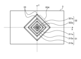
- FIG. 6 is an enlarged top view of a portion of the opening forming layer.
- the opening forming layer 3 has a cross-shaped opening 311 which is a fin inlet 31 aligned along the X-axis and Y-axis. That is, the cross-shaped opening 311 has a shape that is four-fold rotationally symmetric with respect to the origin, and extends planarly in two dimensions. That is, the cross-shaped opening 311 does not extend in one dimension, but has a shape that is four-fold rotationally symmetric with respect to the origin in a two-dimensional plane, and is composed of openings that extend in multiple directions.
- the opening forming layer 3 has openings 312 and 313, which are fin inlets 31, and openings 321 and 322, which are fin outlets 32, at positions radially away from the origin with respect to the cross-shaped opening 311.
- multiple openings 311, 312, 313, 321, and 322 are formed in the metal layer.
- Similar openings are also formed in the second, third, and fourth quadrants.
- the shape of the opening in the region where the fin arrangement region R20 of the opening forming layer 3 is projected has four-fold rotational symmetry around the origin.
- Opening 321 adjacent to cross-shaped opening 311 is positioned at a fixed distance from cross-shaped opening 311 in both the X-axis and Y-axis directions. In other words, it does not extend linearly in one direction, but extends planarly in two dimensions.
- opening 321 has an L-shape in which an opening extending in the X-axis direction and an opening extending in the Y-axis direction are connected at a position on a line in a direction of about 45° from the X-axis, and bends vertically at this position.
- Opening 312 adjacent to opening 321, opening 322 following opening 312, and opening 313 following opening 322 similarly extend planarly in two dimensions, and have an L-shape bent vertically at a position on a line in a direction of about 45° from the X-axis.
- the cross-shaped opening 311 and the L-shaped openings 312 and 313 form the fin inlets 31 in the fin arrangement region R20, and are connected to the inlet 71 through openings formed in the layers from the flow path forming layer 4 to the inlet/outlet arrangement layer 7.
- the L-shaped openings 321, 322 are the fin outlets 32 of the fin arrangement region R20, and are connected to the outlet 72 through openings formed in the layers from the flow path forming layer 4 to the inlet/outlet arrangement layer 7.
- the cross-shaped opening 311 and the L-shaped openings 312, 313 which are the fin inlet 31 for flowing the refrigerant into the fin arrangement region R20, and the L-shaped openings 321, 322 which are the fin outlet 32 are alternately arranged in a direction radially away from the origin.
- the above three elements have different heat dissipation performance, i.e., heat transfer coefficient, that is transferred from the metal layers constituting the base layer 1 and the fin-forming layer 2 to the refrigerant. Furthermore, as the refrigerant flows in through the cross-shaped opening 311, passes through the groove 22 in the fin arrangement region R20, and flows out through the L-shaped opening 321, the temperature of the refrigerant gradually increases.
- the refrigerant flowing in from the L-shaped opening 312 passes through the groove 22 in the fin arrangement region R20 and flows out from the L-shaped openings 321 and 322 adjacent to the L-shaped opening 312.
- the refrigerant flowing in from the L-shaped opening 313 passes through the groove 22 in the fin arrangement region R20 and flows out from the L-shaped opening 322 adjacent to the L-shaped opening 313.
- the flow of the refrigerant in these cases is roughly equivalent to the flow from the cross opening 311, passing through the groove 22 in the fin arrangement region R20, and flowing out from the L-shaped opening 321.
- the fin inlets 31 and fin outlets 32 in the opening forming layer 3 for flowing the refrigerant in the fin arrangement region R20 are arranged alternately from the center toward the periphery. By narrowing the spacing between the alternating arrangement, the temperature distribution can be pushed into a narrow area.
- the fin outlets 32 are placed next to the fin inlets 31.
- the fin inlets 31 are placed next to the fin outlets 32. Therefore, at the fin outlets 32, a flow of coolant is formed from the adjacent fin inlets 31, and since the flow directions are opposite to each other, the temperature distribution is cancelled out. As a result, the temperature distribution can be averaged in a localized area.
- the base layer 1 is made of a metal with good thermal conductivity, the temperature distribution can be reduced.
- the fin inlets 31 and fin outlets 32 for flowing the refrigerant in the fin arrangement region R20 are arranged alternately and in parallel in a direction radially away from the origin, thereby obtaining a concentric temperature distribution.
- the distance that the refrigerant flows through the grooves 22 in the fin arrangement region R20 can be shortened. This makes it possible to suppress an increase in pressure loss when the refrigerant flows through the grooves 22 in the fin formation layer 2.
- the fin inlets 31 and fin outlets 32 which are arranged alternately and in parallel in a direction radially away from a set point in the region obtained by projecting the element placement region R100 onto the opening formation layer 3, are arranged so as to have four-fold rotational symmetry with respect to the set point.
- the shape of the openings formed in the opening formation layer 3 four-fold rotational symmetry, bias in the X-axis and Y-axis directions is suppressed, and it is possible to approach a concentric temperature distribution centered on the set point. Note that the case where the arrangement of the openings is made even higher-order rotational symmetry will be described later.
- the cross-shaped opening 311 in the opening forming layer 3 is a fin inlet 31, not a fin outlet 32.
- the temperature is high at the center of the heat source and low at the periphery of the heat source.
- the origin is located directly below the element 100, which is the heat source. This is because cooling capacity can be improved by flowing a low-temperature fluid into the origin.
- the cross-shaped opening 311 which is the fin inlet 31 directly below the element 100 (heat source), is not only located at or near the origin, but extends planarly in two dimensions from the opening near the origin, as shown in Figures 7 and 11 described below.
- the entire element 100 can be cooled uniformly, improving cooling performance, compared to when openings are located only at or near the origin as shown in Figures 7 and 11 described below.
- the L-shaped openings 312, 313 which are the fin inlet 31 and the L-shaped openings 321, 322 which are the fin outlet 32, which are arranged alternately and in parallel in a direction radially away from a specified point in the region where the element placement region R100 is projected onto the opening formation layer 3, are placed at a fixed distance from the cross-shaped opening 311, thereby making it possible to reduce the temperature distribution. Since the L-shaped openings 312, 313, 321, 322 are placed at a fixed distance from the cross-shaped opening 311, they necessarily extend flatly in two dimensions and have a vertically bent structure.
- FIG. 7 is a top view showing another example of the configuration of the opening formation layer constituting the cooler according to the first embodiment.
- the origin is also the center of the region obtained by projecting the element arrangement region R100 onto the opening formation layer 3.
- a dot-like opening 311a that becomes the fin inlet 31 is provided at the origin.
- linear openings 312a, 313a that become the fin inlet 31 and linear openings 321a, 322a that become the fin outlet 32 are alternately and parallelly arranged in a direction radially away from the origin.
- the linear openings 312a, 313a, 321a, 322a extend in a direction perpendicular to a line that passes through the origin and has an inclination of 45° or ⁇ 45° with respect to the X-axis.
- the arrangement of the openings in the opening formation layer 3 is four-fold rotationally symmetrical with the origin as the center. This allows the temperature distribution to be averaged and to be closer to a concentric circle.
- the structure of the base layer 1 and fin forming layer 2 is bonded to the opening forming layer 3.
- openings are formed from a single metal layer by processing such as etching and cutting as described above.
- the opening forming layer 3 has a support portion 33 for maintaining the structure as a metal layer.
- square openings are formed in parallel in a direction away from the origin, with the origin at the center. The vertices of the square openings overlap with the X-axis and Y-axis, but openings are not formed at these vertices, and support portions 33 remain where the metal layer remains.
- the support portions 33 support the metal layer sandwiched between the openings, and the structure as a metal layer is maintained.
- FIGs 8 to 10 are top views showing other examples of the configuration of the opening forming layer constituting the cooler according to embodiment 1.
- the support parts 33 are shown formed on a straight line passing through the origin and inclined at 45° and -45° from the X axis.
- Figure 9 is a combination of Figures 7 and 8, and shows a case in which the support parts 33 are formed on the X axis and the Y axis, and on a straight line passing through the origin and inclined at 45° and -45° from the X axis.
- the support parts 33 are thin, the temperature distribution is not significantly affected even if the position of the support parts 33 is not at a position that is four times rotationally symmetric about the origin. In other words, when the support parts 33 are formed thin, the support parts 33 can be provided at any position. However, ideally, as shown in Figure 10, it is preferable that the support parts 33 are not provided. In this case, after the metal layer that constitutes the opening forming layer 3 is bonded to the structure of the base layer 1 and the fin forming layer 2, only the metal layer is processed, which makes the manufacturing process complicated.
- the spacing which is the distance between adjacent openings in a direction radially away from the origin, is made wider on the outside than on the inside.
- the spacing between adjacent fin inlets 31 and fin outlets 32 is wider at positions farther from a point in the region onto which the element placement region R100 is projected than at positions closer to that point in the region.
- the spacing between adjacent openings can be made wider the further away from a set point.
- the length of the flow path through which the refrigerant flows is increased in the outer fin arrangement region R20, which is the periphery of the heat source.
- the temperature rise of the outer fluid is greater than the temperature rise of the inner fluid, and the temperature of the periphery of the heat source increases, making it possible to reduce the temperature distribution of the heat source.
- the temperature in the center also increases, so it is necessary to design the spacing between the openings according to the amount of heat generated, the required temperature specifications, and the temperature distribution.
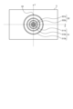
- FIG. 11 is a top view showing another example of the configuration of the opening formation layer that constitutes the cooler according to embodiment 1.
- the origin is set to the center of the region onto which the element placement region R100 is projected.
- arc-shaped openings 311b, 312b, 313b that become the fin inlet 31 and arc-shaped openings 321b, 322b that become the fin outlet 32 are alternately and parallelly arranged in a direction radially away from the origin.
- the arrangement of the openings in the region onto which the element placement region R100 is projected is arranged with four-fold rotational symmetry around the origin.
- the spacing between adjacent openings is wider on the outside than on the inside.
- the fin inlet 31 and the fin outlet 32 are circular in shape by connecting the arc-shaped openings 311b, 312b, 313b, 321b, and 322b with the support 33.
- the shapes of the fin inlet 31 and the fin outlet 32 are also circularly symmetric and have a higher degree of rotational symmetry, so that the temperature distribution can be made more uniform.
- the grooves 22 in the fin arrangement region R20 are often formed by combining straight lines. Therefore, as described above, it is preferable that the openings 311b, 312b, 313b, 321b, and 322b in the opening formation layer 3 coincide with the direction of the openings in the fin arrangement region R20 in terms of suppressing an increase in pressure loss.
- the fins 21 in the fin arrangement region R20 of the fin formation layer 2 so that the grooves 22 are arc-shaped, i.e., circularly symmetric, in accordance with the openings in the opening formation layer 3.
- the manufacture of the circularly symmetric fins 21 and openings is more complicated than that of linear shapes.
- the shapes of the flow paths in the flow path forming layer 4 and the flow path forming layer 5 in FIG. 2 may change.
- the flow paths in the flow path forming layer 4 and the flow path forming layer 5 are arranged so that the refrigerant flowing in from the inlet 71 of the inlet/outlet arrangement layer 7 does not flow out from the outlet 72 of the inlet/outlet arrangement layer 7 without passing through the fins 21.
- the opening of the flow path forming layer 4, i.e., the refrigerant inlet flow path 41, is arranged so that the refrigerant inlet flow path 51 of the flow path forming layer 5 connected to the inlet 71 at least partially overlaps with the fin inlet 31 of the opening forming layer 3 for flowing the refrigerant into the fin arrangement region R20, but does not overlap with the fin outlet 32 of the opening forming layer 3 for discharging the refrigerant from the fin arrangement region R20.
- the opening of the flow path forming layer 4, i.e., the refrigerant outflow flow path 42, is arranged so that the refrigerant outflow flow path 52 of the flow path forming layer 5 connected to the outlet 72 at least partially overlaps with the fin outlet 32 of the opening forming layer 3 for discharging the refrigerant from the fin arrangement region R20, and does not overlap with the fin inlet 31 of the opening forming layer 3 for flowing the refrigerant into the fin arrangement region R20.
- the refrigerant inflow flow path 51 and the refrigerant outflow flow path 52 of the flow path forming layer 5, the refrigerant inflow flow path 41 and the refrigerant outflow flow path 42 of the flow path forming layer 4, and the fin inflow port 31 and the fin outlet port 32 of the opening forming layer 3 are arranged so that the refrigerant that flows in from the inlet 71 of the inlet/outlet arrangement layer 7 does not flow out from the outlet 72 of the inlet/outlet arrangement layer 7 without passing through the fin arrangement region R20.
- one inlet 71 and one outlet 72 are arranged in the cooler 10, so that the refrigerant from the inlet 71 is spread by the flow path connection layer 6 and connected to the refrigerant inlet region R53 of the flow path forming layer 5, and the refrigerant from the refrigerant outlet region R54 of the flow path forming layer 5 is collected by the flow path connection layer 6 and connected to the outlet 72 of the inlet/outlet arrangement layer 7.
- the flow path forming layer 4 and the flow path forming layer 5 can have different shapes in order to connect the multiple inlets 71 to the refrigerant inlet region R53 of the flow path forming layer 5 and connect the multiple outlets 72 to the refrigerant outlet region R54 of the flow path forming layer 5.
- Figures 5 and 6 show the case where the spacing between adjacent L-shaped openings 312, 313, 321, and 322 is constant, the spacing between adjacent L-shaped openings 312, 313, 321, and 322 may be wider on the outside than on the inside, as in the case shown in Figures 7 to 11.
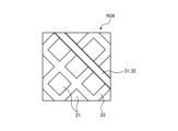
- FIG. 12 is a top view showing a schematic positional relationship between the openings in the opening formation layer and the grooves in the fin arrangement region arranged in the fin formation layer.
- FIG. 12 is an enlarged view of a portion of region R34 in FIG. 7.
- the fin inlet 31 and the fin outlet 32 which are openings in the opening formation layer 3, are arranged in a direction that matches the direction of the openings, which are the grooves 22 between the fins 21 installed in the fin formation layer 2.
- the fin inlet 31 and the fin outlet 32 are arranged in the direction in which the openings formed by the fins 21 on the surface in contact with the opening formation layer 3 extend in the XY plane.
- the adjacent fin inlets 31 and fin outlets 32 in the opening forming layer 3 are arranged radially away from the origin, and therefore have different areas. In other words, the further an opening is from the origin, the smaller the opening area is. Therefore, if the grooves 22 in the fin forming layer 2 are one-dimensional, stagnation occurs, increasing the temperature distribution and decreasing the cooling capacity. For this reason, it is desirable to have a structure in which the grooves 22 in the fin forming layer 2 can expand locally two-dimensionally between the fin inlets 31 and the fin outlets 32. This makes it possible to suppress drift between the fin inlets 31 and the fin outlets 32, eliminate stagnation, and improve cooling performance.
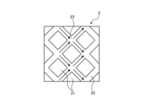
- FIG. 13 is a partially enlarged top view showing an example of the configuration of the fin forming layer constituting the cooler of embodiment 1.
- FIG. 13 is an enlarged view of a part of the fin arrangement region R20 in the fin forming layer 2.
- the flow of the refrigerant in the groove 22 of the fin arrangement region R20 of the fin forming layer 2 shown in FIG. 2 is indicated by arrows.
- the groove 22 in the fin arrangement region R20 has periodicity locally, and repeatedly merges and branches in a narrow region.
- the groove 22 having this periodicity is formed throughout the entire fin arrangement region R20.
- the refrigerant flowing through the groove 22, which is the flow path of the fin arrangement region R20 merges at position 23 and then branches.
- the openings forming the fins 21 are provided so that the refrigerant repeatedly merges and branches between the adjacent fin inlet 31 and fin outlet 32. Therefore, even if the areas of the fin inlet 31 and the fin outlet 32 are different, the flow can be made uniform in two dimensions, that is, in all directions within the plane formed by the X-axis and Y-axis. As a result, the temperature distribution can be reduced, and the cooling capacity can be improved.
- FIG. 14 is a top view showing another example of the configuration of the fin forming layer constituting the cooler according to embodiment 1.
- FIG. 15 is a top view showing an enlarged portion of the fin arrangement region of the fin forming layer in FIG. 14.
- FIG. 15 is a view showing an enlarged portion of region R210 in FIG. 14.
- FIGS. 14 and 15 show an example of the fin forming layer 2 having a different shape of fin 21 from that in FIG. 13, which repeatedly merges and branches locally. In the example of FIGS.
- the fin forming layer 2a has a thin plate 210 in which an opening 211 extending in a first direction is formed in the fin arrangement region R20 including the region where the element arrangement region R100 is projected, and a thin plate 220 in which an opening 221 extending in a second direction intersecting the first direction is formed in the fin arrangement region R20, and has a structure in which multiple thin plates 210 and 220 are alternately stacked.
- the openings 211 extending in the first direction and the openings 221 extending in the second direction overlap to form the fins 21a.
- the openings 211 and the openings 221 are stacked to form the grooves 22a.
- the grooves 22a have a three-dimensional mesh-like structure.
- FIG. 16 is a top view showing an example of the configuration of the opening formation layer corresponding to the fin formation layer of FIG. 14.
- the cross-shaped opening 311c passing through the origin is arranged in the direction of the groove 22a of the fin arrangement region R20 in FIG. 14 and FIG. 15, i.e., in the direction that coincides with the first direction and the second direction.
- the L-shaped openings 312c, 313c, 321c, 322c are arranged in parallel in a direction radially away from the origin, and at a certain distance from the cross opening 311c.
- the coolant flows from the fin inlet 31 of the opening forming layer 3 into the fin arrangement region R20 of the fin forming layer 2. Specifically, the coolant flows in from an opening formed in the fin arrangement region R20 that overlaps with the fin inlet 31.
- the opening formed in the fin arrangement region R20 corresponds to the position of the groove 22a when viewed from the bottom surface of the fin forming layer 2a.
- the coolant flows out from the opening that overlaps with the fin outlet 32 and the fin outlet 32 of the opening forming layer 3.
- the fin 21a shown in FIG. 14 also repeatedly merges and branches in narrow areas.
- the fin 21a shown in FIG. 14 has a flow path that can expand the flow uniformly in two dimensions, that is, in all directions within the plane formed by the X-axis and Y-axis.
- the cooler 10 includes a base layer 1 to which the element 100 is bonded, a fin forming layer 2 having a fin arrangement region R20 in which a plurality of fins 21, 21a connected to the base layer 1 are arranged, and an opening forming layer 3 connected to the fin forming layer 2 and having a plurality of fin inlets 31 and a plurality of fin outlets 32 for flowing a coolant to the fin arrangement region R20.
- the plurality of fin inlets 31 are connected to an inlet 71 through which the coolant of the cooler 10 flows in via an inflow flow path
- the fin outlet 32 is connected to an outlet 72 through which the coolant of the cooler 10 flows out via an outflow flow path.
- the plurality of fin inlets 31 and the plurality of fin outlets 32 are arranged alternately and in parallel in a direction radially away from a point within an area in which the shape of the element 100 is projected onto the opening forming layer 3. This allows the temperature distribution due to the heat generated by the element 100 to approach a concentric shape, and the temperature distribution can be reduced. In addition, it is possible to suppress an increase in the pressure loss of the refrigerant in the fin forming layer 2 between the fin inlet 31 and the fin outlet 32.
- Embodiment 2. 17 is a cross-sectional view showing a schematic example of a configuration of a cooler according to embodiment 2.
- the same components as those described in embodiment 1 are denoted by the same reference numerals, and the description thereof will be omitted.
- the cooler 10a according to embodiment 2 further includes a flow path forming layer 8 between the opening forming layer 3 and the flow path forming layer 4.
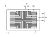
- FIG. 18 is a top view showing an example of the configuration of a flow path forming layer constituting a cooler according to embodiment 2.
- the flow path forming layer 8 is a metal layer having flow paths 81, 82 which are openings in an area that includes the area where the element placement region R100 is projected.
- the area of the flow path forming layer 8 where the flow paths 81, 82 are placed is called the flow path placement region R80.
- the flow path forming layer 8 corresponds to the first flow path forming layer.
- FIG. 19 is a diagram showing an example of a state in which the opening forming layer and the flow path forming layer are overlapped.
- the flow paths 81, 82 of the flow path forming layer 8 that overlap with the area of the opening forming layer 3 other than the opening are shaded.
- the flow path arrangement region R80 includes the element arrangement region R100 and has a larger area than the element arrangement region R100.
- the size of the flow path arrangement region R80 in the Y-axis direction is equal to that of the element arrangement region R100, but the size of the flow path arrangement region R80 in the X-axis direction is larger than that of the element arrangement region R100.
- the flow paths 81, 82 of the flow path arrangement region R80 are arranged to correspond to the openings of the opening forming layer 3.
- the centers of the flow paths 81, 82 of the flow path forming layer 8 in the width direction are arranged so as to coincide with the centers of the width directions of the corresponding openings of the opening forming layer 3.
- the flow passage arrangement region R80 has a cross-shaped opening 81a passing through the origin and L-shaped openings 81b and 82b.
- the L-shaped openings 81b and 82b are arranged in parallel in a direction radially away from the origin.
- the flow passage formation layer 8 has a flow passage arrangement region R80 that includes an area having openings 81a and 81b projected from the fin inlet 31 and openings 82b projected from the fin outlet 32, which are alternately and parallelly arranged in a direction radially away from the origin of the opening formation layer 3. Therefore, the width and length of the flow passages 81 and 82 of the flow passage formation layer 8 are equal to or greater than the width and length of the openings of the opening formation layer 3.
- the refrigerant inlet flow path 41 and the refrigerant outlet flow path 42 which are the openings of the flow path forming layer 4 are basically openings that include the area where the fin inlet 31 and the fin outlet 32, which are the openings of the opening forming layer 3, and the refrigerant inlet flow path 51 and the refrigerant outlet flow path 52, which are the openings of the flow path forming layer 5, are projected onto the flow path forming layer 4.
- an area without an opening in the flow path forming layer 4 occurs directly above the opening of the opening forming layer 3. In this area, the refrigerant does not easily flow to the fin 21. Conversely, an area without an opening in the opening forming layer 3 also occurs at a position corresponding to the opening of the flow path forming layer 4. As a result, the flow becomes biased, the temperature distribution increases, and there is a possibility that the cooling capacity will decrease.
- a flow path forming layer 8 having a flow path arrangement region R80 in which flow paths 81, 82 are formed, which are projections of fin inlets 31 and fin outlets 32 arranged alternately and in parallel in a direction radially away from the origin of the opening forming layer 3, is connected to the opening forming layer 3.
- a wide flow path is provided in the upper part of the opening-free area of the flow path forming layer 4, and the refrigerant flows around it, so that the refrigerant flows evenly to the fins 21. As a result, the temperature distribution can be reduced and the cooling capacity can be improved.
- a wide flow path is also provided in the lower part of the opening-free area of the opening forming layer 3 at a position corresponding to the opening of the flow path forming layer 4, so that the refrigerant flows around it, so that the refrigerant flows evenly to the fins 21.
- the flow paths 81, 82 arranged in the flow path forming layer 8 smooth out the flow bias that occurs at the openings of the flow path forming layer 4. For this reason, by reducing the thickness of the opening forming layer 3 and increasing the thickness of the flow path forming layer 8, specifically by making the thickness of the flow path forming layer 8 thicker than the thickness of the opening forming layer 3, the elimination of the bias in the refrigerant flow is further improved. As a result, the temperature distribution can be further reduced, and the cooling capacity can be improved.
- the cooler 10a according to the second embodiment further includes a flow path forming layer 8 that is connected to the opening forming layer 3, includes a projection area that is an area where the multiple fin inlets 31 and multiple fin outlets 32 of the opening forming layer 3 are projected, and has flow paths 81, 82 that are openings with at least one of the length and width of the multiple fin inlets 31 and multiple fin outlets 32 of the opening forming layer 3 increased in an area larger than the projection area.
- the wide flow paths 81, 82 are installed above the area where there are no openings in the flow path forming layer 4, and the refrigerant flows around and flows evenly through the fins 21. As a result, there is an effect of reducing the temperature distribution and improving the cooling capacity.
- FIG. 20 is a cross-sectional view showing a schematic example of the configuration of a cooler according to the third embodiment.
- the same components as those described in the first embodiment are given the same reference numerals, and the description thereof will be omitted.
- FIG. 20 shows a case where three elements 100 arranged in the same direction, for example, in the X-axis direction, are joined to one cooler 10b. Even in this case, when focusing on the region A of the cooler 10b to which one element 100 is joined, the structure from the base layer 1 to the flow path forming layer 5 is roughly the same as that shown in FIG. 2. The same is true for the elements 100 joined at other positions. That is, the cooler 10b has a configuration in which three of the structures of the metal layers shown in FIG. 2 are arranged in parallel.
- the cooler 10b according to the third embodiment differs from the first embodiment in the configuration of the flow path connection layer 6b and the inlet/outlet arrangement layer 7b, and further includes a flow path distribution layer 9 between the flow path connection layer 6b and the inlet/outlet arrangement layer 7b.
- the flow path connection layer 6b, the flow path distribution layer 9, and the inlet/outlet arrangement layer 7b are joined in this order below the flow path formation layer 5.
- FIG. 21 is a top view showing an example of the configuration of the flow path connection layer constituting the cooler according to embodiment 3.
- the flow path connection layer 6b has an inflow connection port 61b and an outflow connection port 62b at positions corresponding to each of the three elements 100.
- the inflow connection port 61 and the outflow connection port 62 are in the same position in the Y-axis direction
- the inflow connection port 61b and the outflow connection port 62b are shifted in the Y-axis direction.
- the inflow connection port 61b is shifted by a distance ⁇ y determined in the positive direction of the Y-axis compared to the outflow connection port 62b.
- the flow path distribution layer 9 is a metal layer having a flow path that distributes the refrigerant flowing in from the inlet 71b of the inlet/outlet arrangement layer 7b to each inlet connection port 61b of the flow path connection layer 6b, and merges the refrigerant from each outlet connection port 62b of the flow path connection layer 6b into the outlet port 72b of the flow path connection layer 7b.
- FIG. 22 is a top view showing an example of the configuration of the flow path distribution layer constituting the cooler according to embodiment 3. As shown in FIG.
- the flow path distribution layer 9 has a distribution flow path 91 that distributes the refrigerant from the inlet 71b to the inlet connection port 61b of the flow path connection layer 6b, and a merge flow path 92 that merges the refrigerant from the outlet connection port 62b of the flow path connection layer 6b into the outlet port 72b.
- the distribution flow path 91 is arranged so as to intersect with the inlet connection port 61b of the flow path connection layer 6b, but not with the outlet connection port 62b.
- the merging flow path 92 is arranged so as to intersect with the outlet connection port 62b of the flow path connection layer 6b, but not with the inlet connection port 61b.
- the distribution flow path 91 is arranged on the positive side of the merging flow path 92 in the Y-axis direction.
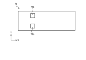
- the inlet/outlet arrangement layer 7b has one inlet 71b and one outlet 72b.
- the inlet 71b is arranged at a position intersecting with the distribution flow path 91 of the flow path distribution layer 9.
- the outlet 72b is arranged at a position intersecting with the merging flow path 92 of the flow path distribution layer 9.
- the inlet 71b and the outlet 72b are arranged at a position corresponding to the leftmost element 100 in FIG.
- the inlet 71b and the outlet 72b can be arranged at any position as long as the inlet 71b intersects with the distribution flow path 91 of the flow path distribution layer 9 and the outlet 72b intersects with the merging flow path 92 of the flow path distribution layer 9.
- three elements 100 are arranged in the cooler 10b, but there is only one inlet 71b and one outlet 72b.
- the flow path distribution layer 9 having the distribution flow path 91 connecting one inlet 71b to the inlet connection port 61b of the flow path connection layer 6b provided corresponding to each of the three elements 100, and the merging flow path 92 connecting one outlet 72b to the outlet connection port 62b of the flow path connection layer 6b provided corresponding to each of the three elements 100 is inserted between the flow path connection layer 6b and the inlet/outlet arrangement layer 7b.
- the refrigerant flowing in from the inlet 71b of the inlet/outlet arrangement layer 7b passes through the distribution flow path 91 and flows to the inlet connection port 61b connected to the fin 21 that cools each element 100.
- the refrigerant reaches the fin 21 and returns to the outlet connection port 62b.
- the refrigerant flowing out from the outlet connection port 62b passes through the merging flow path 92 and is discharged from the outlet 72b of the inlet/outlet arrangement layer 7b.
- the X-axis direction corresponds to the third direction
- the Y-axis direction corresponds to the fourth direction.
- FIG. 21 is a top view showing an example of the configuration of the flow path connection layer that constitutes the cooler according to the third embodiment. As shown in FIG.
- the fin arrangement regions R20 provided in each of the three elements 100 are connected to form one fin arrangement region.
- the fin arrangement region projected onto the flow path connection layer 6b is the fin projection region R20c shown by the dashed line. In this way, the fins 21 may be provided on the entire surface of the fin formation layer 2.
- a plurality of elements 100 are arranged in one direction, and each element 100 has the same structure as that described in the first embodiment from the base layer 1 to the flow path forming layer 5, and below the flow path forming layer 5, there is a flow path connection layer 6b, a flow path distribution layer 9, and an inlet/outlet arrangement layer 7b.
- the position of the inlet connection port 61b is shifted along the extension direction compared to the position of the outlet connection port 62b.
- the flow path distribution layer 9 has a distribution flow path 91 connecting the plurality of inlet connection ports 61b of the flow path connection layer 6b, and a merging flow path 92 connecting the plurality of outlet connection ports 62b.
- the inlet/outlet arrangement layer 7b has an inlet 71b provided at a part of the position corresponding to the distribution flow path 91, and an outlet 72b provided at a part of the position corresponding to the merging flow path 92.
Landscapes
- Cooling Or The Like Of Semiconductors Or Solid State Devices (AREA)
Priority Applications (4)
| Application Number | Priority Date | Filing Date | Title |
|---|---|---|---|
| JP2025516334A JP7829807B2 (ja) | 2023-04-24 | 2023-04-24 | 冷却器 |
| DE112023006272.2T DE112023006272T5 (de) | 2023-04-24 | 2023-04-24 | Kühler |
| CN202380097307.5A CN121039807A (zh) | 2023-04-24 | 2023-04-24 | 冷却器 |
| PCT/JP2023/016172 WO2024224460A1 (ja) | 2023-04-24 | 2023-04-24 | 冷却器 |
Applications Claiming Priority (1)
| Application Number | Priority Date | Filing Date | Title |
|---|---|---|---|
| PCT/JP2023/016172 WO2024224460A1 (ja) | 2023-04-24 | 2023-04-24 | 冷却器 |
Publications (1)
| Publication Number | Publication Date |
|---|---|
| WO2024224460A1 true WO2024224460A1 (ja) | 2024-10-31 |
Family
ID=93256046
Family Applications (1)
| Application Number | Title | Priority Date | Filing Date |
|---|---|---|---|
| PCT/JP2023/016172 Ceased WO2024224460A1 (ja) | 2023-04-24 | 2023-04-24 | 冷却器 |
Country Status (4)
| Country | Link |
|---|---|
| JP (1) | JP7829807B2 (https=) |
| CN (1) | CN121039807A (https=) |
| DE (1) | DE112023006272T5 (https=) |
| WO (1) | WO2024224460A1 (https=) |
Citations (4)
| Publication number | Priority date | Publication date | Assignee | Title |
|---|---|---|---|---|
| JP2001160649A (ja) * | 1999-10-21 | 2001-06-12 | Jenoptik Ag | ダイオードレーザを冷却する装置 |
| JP2003051689A (ja) * | 2001-08-06 | 2003-02-21 | Toshiba Corp | 発熱素子用冷却装置 |
| JP2014017412A (ja) * | 2012-07-10 | 2014-01-30 | Nippon Soken Inc | 熱拡散装置 |
| WO2021044550A1 (ja) * | 2019-09-04 | 2021-03-11 | 三菱電機株式会社 | ヒートシンクおよび半導体モジュール |
Family Cites Families (4)
| Publication number | Priority date | Publication date | Assignee | Title |
|---|---|---|---|---|
| JP2010098204A (ja) | 2008-10-20 | 2010-04-30 | Stanley Electric Co Ltd | 光源の冷却構造 |
| US8929071B2 (en) | 2008-12-22 | 2015-01-06 | General Electric Company | Low cost manufacturing of micro-channel heatsink |
| US8391008B2 (en) | 2011-02-17 | 2013-03-05 | Toyota Motor Engineering & Manufacturing North America, Inc. | Power electronics modules and power electronics module assemblies |
| EP4113596A4 (en) | 2020-02-26 | 2024-03-27 | Kyocera Corporation | HEAT DISSIPATION ELEMENT |
-
2023
- 2023-04-24 DE DE112023006272.2T patent/DE112023006272T5/de active Pending
- 2023-04-24 CN CN202380097307.5A patent/CN121039807A/zh active Pending
- 2023-04-24 WO PCT/JP2023/016172 patent/WO2024224460A1/ja not_active Ceased
- 2023-04-24 JP JP2025516334A patent/JP7829807B2/ja active Active
Patent Citations (4)
| Publication number | Priority date | Publication date | Assignee | Title |
|---|---|---|---|---|
| JP2001160649A (ja) * | 1999-10-21 | 2001-06-12 | Jenoptik Ag | ダイオードレーザを冷却する装置 |
| JP2003051689A (ja) * | 2001-08-06 | 2003-02-21 | Toshiba Corp | 発熱素子用冷却装置 |
| JP2014017412A (ja) * | 2012-07-10 | 2014-01-30 | Nippon Soken Inc | 熱拡散装置 |
| WO2021044550A1 (ja) * | 2019-09-04 | 2021-03-11 | 三菱電機株式会社 | ヒートシンクおよび半導体モジュール |
Also Published As
| Publication number | Publication date |
|---|---|
| JPWO2024224460A1 (https=) | 2024-10-31 |
| DE112023006272T5 (de) | 2026-04-23 |
| CN121039807A (zh) | 2025-11-28 |
| JP7829807B2 (ja) | 2026-03-13 |
Similar Documents
| Publication | Publication Date | Title |
|---|---|---|
| US8958208B2 (en) | Semiconductor device | |
| US20080290499A1 (en) | Semiconductor device | |
| JP7160216B2 (ja) | 半導体装置 | |
| US12205867B2 (en) | Heat sink and semiconductor module | |
| JP2001284513A (ja) | パワー半導体装置 | |
| CN111699554B (zh) | 冷却器和半导体模块 | |
| JP2023037693A (ja) | 冷却装置 | |
| TWI819731B (zh) | 冷卻系統、電腦系統、以及冷卻方法 | |
| JP7829807B2 (ja) | 冷却器 | |
| JP2008530482A (ja) | 熱交換器製造方法、マイクロ熱交換器製造方法及びマイクロ熱交換器 | |
| KR20220165054A (ko) | 반도체 소자 열관리 모듈 및 이의 제조 방법 | |
| TW202239302A (zh) | 液冷散熱結構 | |
| CN113038800B (zh) | 液冷散热结构 | |
| WO2023063192A1 (ja) | 放熱部材 | |
| CN116420227B (zh) | 半导体装置 | |
| WO2023181914A1 (ja) | 放熱部材、冷却装置、および半導体モジュール | |
| CN116259593A (zh) | 一种散热板结构、集成电路模块及其制作方法 | |
| JP2023109210A (ja) | 半導体装置 | |
| CN118140109A (zh) | 散热器和散热器的制造方法 | |
| JP6465943B1 (ja) | ヒートシンクおよび半導体モジュール | |
| JP7580667B1 (ja) | 電力変換装置 | |
| US20240379499A1 (en) | Cooler and semiconductor device | |
| JP7653847B2 (ja) | 冷却装置 | |
| JP2024034334A (ja) | 放熱部材 | |
| JP2024034337A (ja) | 放熱部材 |
Legal Events
| Date | Code | Title | Description |
|---|---|---|---|
| 121 | Ep: the epo has been informed by wipo that ep was designated in this application |
Ref document number: 23935241 Country of ref document: EP Kind code of ref document: A1 |
|
| WWE | Wipo information: entry into national phase |
Ref document number: 2025516334 Country of ref document: JP |
|
| WWE | Wipo information: entry into national phase |
Ref document number: 112023006272 Country of ref document: DE |
|
| 122 | Ep: pct application non-entry in european phase |
Ref document number: 23935241 Country of ref document: EP Kind code of ref document: A1 |