WO2024218918A1 - レーザ照射装置、レーザ加工装置、レーザ加工方法、レーザ露光装置、レーザ露光方法、マスクの設置方法、レーザ加工装置の設置方法、レーザ露光装置の設置方法、マスク及びレーザ照射システム - Google Patents
レーザ照射装置、レーザ加工装置、レーザ加工方法、レーザ露光装置、レーザ露光方法、マスクの設置方法、レーザ加工装置の設置方法、レーザ露光装置の設置方法、マスク及びレーザ照射システム Download PDFInfo
- Publication number
- WO2024218918A1 WO2024218918A1 PCT/JP2023/015669 JP2023015669W WO2024218918A1 WO 2024218918 A1 WO2024218918 A1 WO 2024218918A1 JP 2023015669 W JP2023015669 W JP 2023015669W WO 2024218918 A1 WO2024218918 A1 WO 2024218918A1
- Authority
- WO
- WIPO (PCT)
- Prior art keywords
- mask
- laser
- irradiation
- optical function
- function unit
- Prior art date
- Legal status (The legal status is an assumption and is not a legal conclusion. Google has not performed a legal analysis and makes no representation as to the accuracy of the status listed.)
- Ceased
Links
Images





Classifications
-
- B—PERFORMING OPERATIONS; TRANSPORTING
- B23—MACHINE TOOLS; METAL-WORKING NOT OTHERWISE PROVIDED FOR
- B23K—SOLDERING OR UNSOLDERING; WELDING; CLADDING OR PLATING BY SOLDERING OR WELDING; CUTTING BY APPLYING HEAT LOCALLY, e.g. FLAME CUTTING; WORKING BY LASER BEAM
- B23K26/00—Working by laser beam, e.g. welding, cutting or boring
- B23K26/02—Positioning or observing the workpiece, e.g. with respect to the point of impact; Aligning, aiming or focusing the laser beam
- B23K26/06—Shaping the laser beam, e.g. by masks or multi-focusing
- B23K26/064—Shaping the laser beam, e.g. by masks or multi-focusing by means of optical elements, e.g. lenses, mirrors or prisms
- B23K26/066—Shaping the laser beam, e.g. by masks or multi-focusing by means of optical elements, e.g. lenses, mirrors or prisms by using masks
-
- B—PERFORMING OPERATIONS; TRANSPORTING
- B23—MACHINE TOOLS; METAL-WORKING NOT OTHERWISE PROVIDED FOR
- B23K—SOLDERING OR UNSOLDERING; WELDING; CLADDING OR PLATING BY SOLDERING OR WELDING; CUTTING BY APPLYING HEAT LOCALLY, e.g. FLAME CUTTING; WORKING BY LASER BEAM
- B23K26/00—Working by laser beam, e.g. welding, cutting or boring
- B23K26/02—Positioning or observing the workpiece, e.g. with respect to the point of impact; Aligning, aiming or focusing the laser beam
- B23K26/06—Shaping the laser beam, e.g. by masks or multi-focusing
- B23K26/064—Shaping the laser beam, e.g. by masks or multi-focusing by means of optical elements, e.g. lenses, mirrors or prisms
- B23K26/0648—Shaping the laser beam, e.g. by masks or multi-focusing by means of optical elements, e.g. lenses, mirrors or prisms comprising lenses
-
- B—PERFORMING OPERATIONS; TRANSPORTING
- B23—MACHINE TOOLS; METAL-WORKING NOT OTHERWISE PROVIDED FOR
- B23K—SOLDERING OR UNSOLDERING; WELDING; CLADDING OR PLATING BY SOLDERING OR WELDING; CUTTING BY APPLYING HEAT LOCALLY, e.g. FLAME CUTTING; WORKING BY LASER BEAM
- B23K26/00—Working by laser beam, e.g. welding, cutting or boring
- B23K26/08—Devices involving relative movement between laser beam and workpiece
- B23K26/083—Devices involving movement of the workpiece in at least one axial direction
- B23K26/0853—Devices involving movement of the workpiece in at least two axial directions, e.g. in a plane
-
- B—PERFORMING OPERATIONS; TRANSPORTING
- B23—MACHINE TOOLS; METAL-WORKING NOT OTHERWISE PROVIDED FOR
- B23K—SOLDERING OR UNSOLDERING; WELDING; CLADDING OR PLATING BY SOLDERING OR WELDING; CUTTING BY APPLYING HEAT LOCALLY, e.g. FLAME CUTTING; WORKING BY LASER BEAM
- B23K26/00—Working by laser beam, e.g. welding, cutting or boring
- B23K26/08—Devices involving relative movement between laser beam and workpiece
- B23K26/10—Devices involving relative movement between laser beam and workpiece using a fixed support, i.e. involving moving the laser beam
-
- B—PERFORMING OPERATIONS; TRANSPORTING
- B23—MACHINE TOOLS; METAL-WORKING NOT OTHERWISE PROVIDED FOR
- B23K—SOLDERING OR UNSOLDERING; WELDING; CLADDING OR PLATING BY SOLDERING OR WELDING; CUTTING BY APPLYING HEAT LOCALLY, e.g. FLAME CUTTING; WORKING BY LASER BEAM
- B23K26/00—Working by laser beam, e.g. welding, cutting or boring
- B23K26/352—Working by laser beam, e.g. welding, cutting or boring for surface treatment
- B23K26/354—Working by laser beam, e.g. welding, cutting or boring for surface treatment by melting
-
- H—ELECTRICITY
- H10—SEMICONDUCTOR DEVICES; ELECTRIC SOLID-STATE DEVICES NOT OTHERWISE PROVIDED FOR
- H10P—GENERIC PROCESSES OR APPARATUS FOR THE MANUFACTURE OR TREATMENT OF DEVICES COVERED BY CLASS H10
- H10P72/00—Handling or holding of wafers, substrates or devices during manufacture or treatment thereof
- H10P72/04—Apparatus for manufacture or treatment
- H10P72/0428—Apparatus for mechanical treatment or grinding or cutting
-
- B—PERFORMING OPERATIONS; TRANSPORTING
- B23—MACHINE TOOLS; METAL-WORKING NOT OTHERWISE PROVIDED FOR
- B23K—SOLDERING OR UNSOLDERING; WELDING; CLADDING OR PLATING BY SOLDERING OR WELDING; CUTTING BY APPLYING HEAT LOCALLY, e.g. FLAME CUTTING; WORKING BY LASER BEAM
- B23K2101/00—Articles made by soldering, welding or cutting
- B23K2101/36—Electric or electronic devices
- B23K2101/40—Semiconductor devices
Definitions
- the present invention relates to a laser irradiation device, a laser processing device, a laser processing method, a laser exposure device, a laser exposure method, a mask installation method, a laser processing device installation method, a laser exposure device installation method, a mask, and a laser irradiation system.
- SoC System on a Chip
- trenches are formed in the substrate and wiring is formed along them in order to create through holes (VIAs) for connecting multiple layers of wiring, and to solve the problem of increased wiring resistance.
- VIPs through holes
- a build-up film is laminated on both sides of an inner layer substrate (core layer) made of glass epoxy resin material using a dedicated vacuum laminator.
- the surface of the build-up film thus obtained is processed to provide the above-mentioned through holes and trenches, and a metal layer is formed on it by plating to form electrodes.
- Patent document 1 describes an invention related to a laser drilling method and device.
- claim 1 of patent document 1 describes irradiating a linear or rectangular beam through a contact mask onto a processing area of a substrate to be processed using a contact mask method, and scanning the linear or rectangular beam across the contact mask.
- Patent document 2 describes an invention relating to a processing device and processing method for ablation processing.
- the processing device for ablation processing described in claim 1 of patent document 2 is equipped with a scanning mechanism that moves a line beam forming section containing a line beam forming optical system relative to the device body and scans a line-shaped light.
- the mask In recent years, increasingly large masks have been used in laser irradiation devices used in processing devices, exposure devices, and the like. In these conventional technologies, the mask is often placed horizontally so that it is in the same horizontal direction as the installation surface of the device. Therefore, as the mask becomes larger, the problem of the mask bending significantly due to its own weight occurs. This can lead to a risk of reduced image performance during exposure, and reduced processing accuracy during processing. This problem becomes more pronounced as the mask size increases and the mask becomes thinner. To address this problem, the mask can be made thicker and its rigidity increased in line with the increase in size, thereby suppressing bending when placed horizontally to some extent. However, the method of making the mask thicker significantly increases the mask weight, and there is concern that this may worsen the handling properties of the mask, such as when it is installed.
- the present invention has been made to solve the above problems, and aims to provide a laser irradiation device that can suppress problems such as bending of the mask due to its own weight, even when a large mask is used, and a method of installing a mask to create such a laser irradiation device.
- the present invention provides a laser irradiation device that has a first optical function unit equipped with a laser light source and a second optical function unit for installing a mask having a pattern corresponding to the laser irradiation area of an irradiated object, and irradiates a laser onto an irradiated object through the mask installed on the second optical function unit, the mask including an effective area having a pattern corresponding to the laser irradiation area of the irradiated object, the mask being a rectangle with the shortest side of the four sides that are the outer edge of the mask being 1000 mm or longer in length, and the second optical function unit being disposed so that the normal to the surface on which the pattern is formed faces substantially horizontally.
- the effects of bending due to the mask's own weight can be suppressed, allowing for highly accurate laser irradiation, and dust adhesion to the mask surface can also be suppressed, making it less likely for defects to occur due to dust. Furthermore, since most of the long optical path can be aligned along the horizontal plane, the height of the device can be kept low.
- the mask can be a laser irradiation device in which the thickness of the effective area in the laser transmission direction is 10 mm or less.
- the mask is thin, it is easy to handle and low cost, while also being stable and reducing problems such as bending of the mask due to its own weight.
- the present invention is a laser processing device that performs ablation processing on the surface of the irradiated object using the irradiation energy of a laser beam, and can be a laser processing device that includes an irradiation processing section that has a stage that holds the irradiated object, and the above-mentioned laser irradiation device.
- the second optical function unit, the first optical function unit, and the irradiation processing unit can be separated from one another in the laser processing device.
- the laser processing device may further include a mask changer capable of installing and removing the mask from the second optical function unit.
- the present invention can provide a method for laser processing an object by using the above-mentioned laser processing device to perform ablation processing on the surface of the object.
- the present invention provides a laser exposure device that performs an exposure process on the surface of the irradiated object using the irradiation energy of a laser beam, and that includes an exposure section that includes a stage that holds the irradiated object, and the above-mentioned laser irradiation device.
- the second optical function unit, the first optical function unit, and the exposure unit can be separated from one another to form a laser exposure device.
- the laser exposure device may further include a mask changer capable of installing and removing the mask from the second optical function unit.
- the present invention can provide a laser exposure method for an object to be irradiated, which uses the above-mentioned laser exposure device to perform an exposure process on the surface of the object to be irradiated.
- the present invention has been made to achieve the above object, and provides a method of installing a mask in a laser irradiation device that includes a first optical function unit equipped with a laser light source and a second optical function unit for installing a mask having a pattern corresponding to a laser irradiation area of an irradiated object, and that irradiates the irradiated object with a laser through the mask installed in the second optical function unit, the method using a rectangular mask with the shortest side of the four outer edges being 1000 mm or longer in length, and installing the mask in the second optical function unit so that the normal to the surface on which the pattern is formed is oriented in an approximately horizontal direction.
- This method of mounting the mask allows for highly accurate laser irradiation while minimizing the effects of bending due to the mask's own weight, and also prevents dust from adhering to the mask surface, resulting in a laser irradiation device that can reduce defects caused by dust. Furthermore, since most of the long optical path can be aligned along the horizontal plane, the height of the device can be reduced.
- the mask installation method can be such that the thickness of the effective area in the laser transmission direction is 10 mm or less.
- the mask installation method according to the present invention allows for a laser irradiation device that is stable and reduces problems such as bending of the mask due to its own weight, while being easy to handle and low cost because the mask is thin.
- the mask can be installed using a mask changer.
- the present invention provides a method for installing a laser processing device having the laser irradiation device and an irradiation processing section equipped with a stage for holding the irradiated object, in which the second optical function section, the first optical function section, and the irradiation processing section are separable from one another, and the first optical function section, the second optical function section, and the irradiation processing section are transported separately to an installation location of the laser processing device, and then the laser processing device is integrated at the installation location of the laser processing device, and a mask is installed on the second optical function section before or after the transport using the above-mentioned mask installation method.
- a method for installing a laser exposure device having the laser irradiation device and an exposure section equipped with a stage for holding the irradiated object in which the second optical function section, the first optical function section, and the exposure section are separable from one another, and the first optical function section, the second optical function section, and the exposure section are each transported separately to a location where the laser exposure device is installed, and then the laser exposure device is integrated at the location where the laser exposure device is installed, and a mask is installed on the second optical function section before or after the transport using the above-mentioned mask installation method.
- the present invention also provides a rectangular mask that is installed vertically in a laser irradiation device, includes an effective area having a pattern corresponding to the laser irradiation area of the irradiated object, and has a length of 1000 mm or more for the shortest side of the four sides of the rectangle.
- the mask of the present invention reduces the effects of bending due to its own weight, allowing laser irradiation with high precision, and also prevents dust from adhering to the mask surface, making it less likely for defects to occur due to dust. Furthermore, since most of the long optical path can be aligned along a horizontal plane, the height of the device can be reduced.
- the present invention also provides a laser irradiation system that includes a first optical function unit having a laser light source and a second optical function unit for installing a mask having a pattern corresponding to the laser irradiation area of the irradiated object, and irradiates the irradiated object with a laser through the mask installed in the second optical function unit, the mask including an effective area having a pattern corresponding to the laser irradiation area of the irradiated object, the mask being a rectangle with the shortest side of the four sides that are the outer edge of the mask being 1000 mm or longer in length, and the second optical function unit being disposed so that the normal to the surface on which the pattern is formed is oriented in an approximately horizontal direction.
- the laser irradiation system of the present invention can suppress the effects of deflection due to the mask's own weight, allowing for high-precision laser irradiation, and also suppresses the adhesion of dust to the mask surface, making it less likely for defects to occur due to dust. Furthermore, since most of the long optical path can be aligned along the horizontal plane, the height of the laser irradiation system can be reduced.
- the laser irradiation device and laser irradiation system of the present invention can suppress the effects of bending due to the mask's own weight, allowing for high-precision laser irradiation, and also suppresses the adhesion of dust to the mask surface, making it less likely for defects to occur due to dust. Furthermore, since most of the long optical path can be aligned along the horizontal plane, the height of the device can be kept low.
- the laser processing device/exposure device of the present invention Furthermore, with the laser processing device/exposure device of the present invention, problems such as mask bending due to the mask's own weight and dirt adhesion to the mask are suppressed. With the laser processing method/exposure processing method of the present invention, it is possible to perform high-precision processing/exposure processing while preventing mask deformation and dirt adhesion to the mask.
- the mask installation method of the present invention allows for high-precision laser irradiation while suppressing the effects of deflection due to the mask's own weight, and also prevents dust from adhering to the mask surface, making it possible to produce a laser irradiation device that can suppress defects due to dust. Furthermore, since most of the long optical path can be aligned along the horizontal surface, the height of the device can be reduced.
- the laser processing device/exposure device installation method of the present invention allows for high-precision laser irradiation while suppressing the effects of deflection due to the mask's own weight, and also prevents dust from adhering to the mask surface, making it possible to suppress defects due to dust. Furthermore, since most of the long optical path can be aligned along the horizontal surface, the height of the device can be reduced while reducing the installation costs of the device.
- the mask of the present invention suppresses the effects of bending due to its own weight, allowing laser irradiation with high precision, and also suppresses the adhesion of dust to the mask surface, making it less likely for defects to occur due to dust. Furthermore, since most of the long optical path can be aligned along the horizontal plane, the height of the device can be reduced.
- FIG. 1 is a diagram showing an example of a laser irradiation processing apparatus (laser processing apparatus, exposure apparatus) including a laser irradiation apparatus according to the present invention.
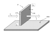
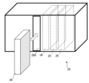
- FIG. 2 is a conceptual diagram showing the arrangement of a mask according to the present invention.
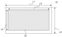
- FIG. 2 is a schematic diagram showing an example of a mask.
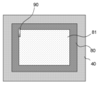
- 1 is a diagram showing an example of a relationship between a processed region of an irradiated object and an irradiated area;
- FIG. 13 is a diagram illustrating an example of overlapping irradiation in one axial direction.
- FIG. 13 is a diagram illustrating an example of overlapping irradiation from the first row to the third row.
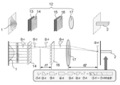
- FIG. 1 is a conceptual diagram of shaping the irradiation shape of a laser beam in an example of a shaping optical system.
- 1 is a schematic diagram showing an example of the configuration of a laser irradiation processing apparatus (laser processing apparatus, exposure apparatus) including a laser irradiation apparatus according to the present invention.
- FIG. 2 is a schematic diagram for explaining an example of a vertical mask changer.
- 1 is a schematic diagram of a cassette storage device that may be equipped with an example of a vertical mask changer.
- a laser irradiation device comprising a first optical function unit having a laser light source and a second optical function unit for mounting a mask having a pattern corresponding to the laser irradiation region of the irradiated object, and for irradiating the irradiated object with a laser through the mask mounted on the second optical function unit, the mask including an effective area having a pattern corresponding to the laser irradiation region of the irradiated object, a rectangular shape with a length of 1000 mm or more among the four sides that are the outer edge of the mask, and arranged so that the normal line of the surface on which the pattern is formed in the second optical function unit faces in a substantially horizontal direction, suppresses the effects of deflection due to the mask's own weight, enables laser irradiation with high accuracy, and also suppresses the adhesion of dust to the mask surface, making it less likely for defects to occur due to dust, and furthermore
- a method of installing a mask in a laser irradiation device that includes a first optical function unit having a laser light source and a second optical function unit for installing a mask having a pattern corresponding to the laser irradiation area of an irradiated object, and that irradiates the irradiated object with a laser through the mask installed in the second optical function unit, using a rectangular mask with a length of 1000 mm or more among the four sides that are the outer edge, and installing the mask in the second optical function unit so that the normal line of the surface on which the pattern is formed faces in a substantially horizontal direction, enables laser irradiation with high precision while suppressing the effects of bending due to the mask's own weight, and can suppress the adhesion of dust to the mask surface, thereby making it possible to achieve a laser irradiation device that can suppress defects due to dust, and furthermore, can reduce the height of the device because most of the long optical path can be aligned along the horizontal plane,
- FIG. 1 is a schematic diagram showing an example of a laser processing apparatus including a laser irradiation apparatus according to the present invention.
- the laser irradiation apparatus 100 shown in Fig. 1 includes a first optical function unit 10 having a laser light source (laser oscillator) 11, and a second optical function unit 20 for installing a mask having a pattern corresponding to a laser irradiation area of an irradiated object 80.
- the laser irradiation apparatus is for irradiating the irradiated object 80 with a laser 1 from the laser light source 11 through a mask 21 installed in the second optical function unit 20.
- the mask 21 includes an effective area 22 having a pattern corresponding to the laser irradiation region of the irradiated object 80.
- the mask according to the present invention includes an effective area 22 having a pattern corresponding to the laser irradiation region of the irradiated object 80, and is a rectangle having a length of 1000 mm or more of the shortest side (the shorter of L1 and L2 in FIG. 3) of the four sides that are the outer edge of the mask.
- the mask according to the present invention may have a ratio (length/thickness) of the length of the shortest side of the four sides that are the outer edge of the rectangular mask 21 to the thickness of the effective area in the laser transmission direction of 100 or more.
- This ratio is more preferably 150 or more, and even more preferably 200 or more. There is no particular limit to the upper limit, but it is about 250 from the viewpoint of ease of handling.
- the length of the shortest side of the four sides means the length of one side of the square.
- a quadrangle does not mean a strict quadrangle, and the four corners may be chamfered with straight lines or curves, and the shape may have a notch or protrusion midway along a side to serve as a receiving portion for a fixing jig or a handling jig.
- the mask according to the present invention is arranged in the second optical function unit 20 so that the normal to the surface on which the pattern is formed faces approximately horizontally.
- the mask 21 is arranged so that two opposing sides 21A, 21B of the four sides that form the outer edge of the mask 21 are approximately perpendicular to the surface 100A on which the laser irradiation device 100 is placed.
- the mask 21 can be said to be arranged in the second optical function unit 20 so that the normal to the surface on which the pattern is formed faces the in-plane direction of the surface 100A.
- the above arrangement is sometimes simply referred to as being arranged "vertically".
- the supports When inserting supports under the mask to prevent bending, the supports must be optically transparent, but as the mask becomes larger, the support material must be thicker, which not only creates cost problems but also increases the absorption of laser energy in the support material, reducing the energy efficiency of the laser irradiation.
- the optical path length from the laser light source to the substrate is long, if the mask is placed horizontally, the height of the equipment becomes large. By placing the mask vertically, it becomes possible to lower the height of the equipment.
- the laser irradiation processing device of the present invention by arranging the mask 21 so that the normal to the surface on which the pattern is formed faces approximately horizontally, bending of the mask 21 is suppressed. And because there is no need for support to prevent bending using an optically transparent material, the efficiency of using laser energy is high, and irradiation processing can be performed with high precision and extremely high uniformity. In addition, since the adhesion of dust to the mask surface can be suppressed, a laser irradiation device can be created that can suppress defects caused by dust. Furthermore, since most of the long optical path can be aligned along the horizontal surface, the height of the device can be reduced. This also makes it possible to realize a pellicle-less system.
- the surface 100A on which the laser irradiation device 100 is placed can be a horizontal surface.
- arranging the mask 21 so that the normal to the patterned surface faces approximately horizontally means arranging it so that it faces horizontally by design, and includes a range of deviation from the horizontal direction within the range of manufacturing and installation errors.
- the upper limits of the dimensions L1 and L2 are not particularly limited, but may be, for example, 2500 mm or more, or may be 2000 mm.
- the upper limits of the dimensions L3 and L4 are not particularly limited, but may be, for example, 2350 mm or more, or may be 1850 mm.
- the present invention is more effective when the size of the mask is large, and is even more effective when such dimensions L1 and L2 are 1500 mm or more, or 1700 mm or more. These dimensional conditions may be satisfied by both L1 and L2, or by only one of them.
- the second optical function unit 20 can further shape the irradiation shape of the laser beam 2 that has passed through the first optical function unit 10 through a mask 21.
- the second optical function unit 20 can further shape the irradiation shape of the laser beam 2 that has been molded into a rectangular shape, for example, according to a pattern that corresponds to the irradiation area 81 of the irradiated body 80.
- the laser beam 3 having an irradiation shape as shown in FIG. 1(c) after passing through the second optical function unit 20 may be changed in its traveling direction by an optional folding mirror 50 as shown in FIG. 1(d) and may be configured to be incident on an optional third optical function unit 30 (described later).
- the laser beam 3 emitted from the third optical function unit 30 is configured to be irradiated onto a portion of the irradiated object 80 held on the stage 40.
- the laser irradiation device 100 preferably further includes a third optical function unit 30 equipped with a reduction projection optical system 31 between the second optical function unit 20 and the stage 40 that holds the object to be irradiated.
- the irradiation area of the laser beam 3 that has passed through the mask 21 can be reduced through an optional reduction optical system 31 described below, thereby increasing the energy density of the laser beam 4 irradiated onto the substrate. Therefore, even if the mask 21 is made large, the targeted fine irradiation process can be performed by using a reduction optical system 31 that matches the mask 21.
- the energy of the laser beam 2 that strikes the mask 21 can be made smaller than the laser irradiation processing energy. If the reduction ratio of the reduction projection optical system 31 is N, the energy of the laser beam that strikes the mask surface is 1/(N 2 ) compared to the laser irradiation energy on the surface of the irradiated object 80. This makes it possible to suppress thermal drift caused by the energy of the laser beam 2, thereby suppressing the thermal expansion of the mask 21 and enabling high-precision laser irradiation processing to be performed even after a long period of laser irradiation operation.
- optical components e.g., the shaping optical system 12 and mask 21
- deterioration of optical components caused by the heat of the laser beam can be suppressed, thereby extending the lifespan of the optical components.
- the reduction projection optical system 31 can be equipped with a pair of reduction projection lenses.
- the magnification by the reduction projection optical system 31 can be adjusted, for example, by the ratio of the focal lengths of the reduction projection lenses and the distance between the reduction projection lenses.
- the reduction magnification N can be, for example, 2 or more, preferably 3 or more, and more preferably 4 or more. There is no particular upper limit, but it is about 5 from the viewpoint of the laser resistance of the mask and the laser energy density required to process the required workpiece.
- the reduction projection lens is preferably one with a high NA (numerical aperture). By using a reduction projection lens with a high NA, it is possible to form vias and trenches that are closer to a cylindrical shape.
- the NA of the reduction projection lens is preferably selected according to the energy density required for the laser irradiation process of the irradiated object 80.
- the NA of the reduction projection lens is preferably 0.12 or more.
- the laser irradiation processing device 200 is configured to non-stop sweep the mask 21 and the substrate stage 40 while irradiating the mask 21 and the substrate stage 40 with pulsed laser beams 2 and 4, respectively, in a sweep irradiation in at least one direction.
- the laser irradiation processing device 200 of the present invention further includes an imaging means for reading the characteristic parts of the irradiated object 80, an imaging means for reading the characteristic parts of the mask 21, and an alignment mechanism for aligning the relative positions of the irradiated object and the mask based on positional information of the characteristic parts of the irradiated object and the mask.
- the laser irradiation processing device 200 shown in FIG. 1 includes a mask alignment camera 23 as an imaging means for reading the characteristic parts of the mask 21, an irradiated object alignment camera 60 as an imaging means for reading the characteristic parts of the irradiated object 80, and an alignment mechanism (not shown).
- the mask alignment camera 23 is configured to send position information of the characteristic parts of the mask 21 to the alignment mechanism.
- the irradiated object alignment camera 60 is configured to send position information of the characteristic parts of the irradiated object 80 to the alignment mechanism.
- the alignment mechanism is configured to align the relative positions of the irradiated object 80 and the mask 21 based on this position information.
- the laser when processing an irradiated object, the laser is often irradiated across multiple layers, and if the laser irradiation processing position of each layer is not precisely aligned with the desired position, the circuits of each layer may not be connected, or even if they are connected, quality defects such as high conductive resistance will occur. To prevent this, the laser irradiation processing position must be precise.
- the shape of the projected image of the pattern on the mask 21 is not necessarily exactly similar to the shape of the laser irradiation on the irradiated object 80, and the magnification is not always the same due to the effects of thermal expansion, etc. Also, even if the irradiated object 80 is slightly distorted or deformed, it may become necessary to deform the shape of the laser irradiation on the irradiated object 80 relative to the projected image on the mask 21.
- the positions of the mask 21 and the irradiated object 80 are acquired by the imaging means (the mask alignment camera 23 and the irradiated object alignment camera 60), and the projected image of the mask 21 is aligned with the shape of the irradiated object to be laser-irradiated based on this information, thereby enabling accurate laser irradiation of the irradiated object.
- the projection position of the projection image of the mask 21 is acquired by the beam image detection camera 70, and correction is made based on the information of this projection position to optimize the projection magnification by the third optical function unit 30, and the sweep speed during sweep irradiation is also optimized based on the above information.
- This makes it possible to arbitrarily change the vertical and horizontal magnifications of the irradiated body 80 relative to the image of the mask 21 within a certain range, and to apply the optimal laser irradiation processing shape.
- the irradiated object 80 may include an irradiation area onto which a pattern is projected by the laser beam 4 that has passed through the mask 21 (and the optional third optical function unit 30).
- Figure 4 shows the irradiated object 80 placed on the stage 40, and shows an example of the relationship between the irradiation area 90 of the irradiated object 80 onto which the laser beam 3 is irradiated, and the irradiated region 81 of the irradiated object 80. As shown in Figure 4, the irradiation area 90 is smaller than the irradiated region 81 of the irradiated object 80.
- the irradiation area 90 shown in FIG. 4 is an area irradiated by one shot of the pulsed laser beam 4.
- the irradiation area 90 corresponds to the mask irradiation area, which is a part of the effective area 22 of the mask 21, since the pattern is projected by the laser beam that has passed through the mask 21.
- the mask 21 is configured to be scanned along the sweep axes 21X and 21Y shown in FIG. 1.
- the stage 40 is configured to be scanned along the sweep axes 80X and 80Y shown in FIG. 1.
- the laser irradiation processing device 200 of the present invention is configured to sweep-irradiate the mask 21 and the stage 40 with the laser beam 4, and perform laser irradiation processing of the irradiated area 81 of the irradiated object 80.
- the laser irradiation processing device 200 is preferably equipped with a mask changer, and the mask is preferably set using the mask changer.
- the mask may further include a vertical mask changer configured to exchange a plurality of masks. If the processing device is equipped with such a vertical mask changer, it can be a laser irradiation processing device that can easily form various patterns.
- FIG. 9 shows a schematic diagram of an example of a vertical mask changer and an example of mask replacement using the same.
- an example of installing and replacing a mask 21 to be placed in a mask holder 25 shown diagrammatically in FIG. 9(A) is shown.
- This example also uses a mask stocker 26 as part of the vertical mask changer.
- the mask stocker 26 is configured to store multiple masks.
- the mask 21 is removed from the mask stocker 26 using the mask clamp 27.
- the manner in which the mask 21 is held (clamped) by the mask clamp 27 is not particularly limited.
- the mask stocker 26 and the mask clamp 27 constitute a vertical mask changer 28 configured to exchange multiple masks 21.
- the mask 21 is placed in the mask holder 25 while still in a vertical orientation. After placement, the mask clamp 27 is released from its grip (unclamped) as shown in FIG. 9(D).
- the mask clamp 27 holds the mask 21 placed on the mask holder 25 as shown in FIG. 9(E), and then the mask 21 is detached from the mask holder 25 as shown in FIG. 9(F).
- the detached mask 21 is stored in the mask stocker 26 as shown in FIG. 9(G).
- the next mask 21 to be used is removed from the mask stocker 26 in the same manner as shown in FIG. 9(B), and the mask 21 is placed on the mask holder 25 in the procedure described above.
- the laser irradiation processing device 200 may also include a mask cabinet 29 as shown in FIG. 10.
- the mask cabinet 29 is configured to store and transport a plurality of mask stockers 26.
- the mask cabinet 29 includes an opening 29A, and is configured so that the mask stocker 26 storing the desired mask 21 can be moved to the position of the opening 29A while maintaining the mask 21 in a vertical position within the mask cabinet 29.
- the method for installing a mask according to the present invention is a method for installing a mask in a laser irradiation device 100 that includes a first optical function unit 10 having a laser light source 11 and a second optical function unit 20 for installing a mask 21 having a pattern corresponding to a laser irradiation region of an irradiated object 80, and that irradiates the irradiated object 80 with a laser through the mask 21 installed in the second optical function unit 20.
- the mask 21 is a rectangle whose shortest side of the four outer edges is 1000 mm or more in length, and is placed on the second optical function unit 20 so that the normal to the surface on which the pattern is formed faces in a substantially horizontal direction. It is also preferable to use a mask 21 whose ratio (length/thickness) of the length of the shortest side of the four outer edges of the rectangular mask to the thickness of the effective area 22 in the laser transmission direction is 100 or more.
- This method of mounting the mask allows for highly accurate laser irradiation while minimizing the effects of bending due to the mask's own weight, and also prevents dust from adhering to the mask surface, resulting in a laser irradiation device that can reduce defects caused by dust. Furthermore, since most of the long optical path can be aligned along the horizontal plane, the height of the device can be reduced.
- the mask 21 can be one in which the thickness of the effective area 22 in the laser transmission direction is 10 mm or less. This allows for a laser irradiation device that is easy to handle and low-cost because the mask is thin, while also being stable and suppressing problems such as bending of the mask due to its own weight.
- Laser processing equipment by combining the laser irradiation device 100 according to the present invention with a laser irradiation processing section 110A having a stage 40 for holding an irradiated body 80 as a laser irradiation processing section 110, it is possible to provide a laser processing device 200A that forms fine irregularities on the irradiated body 80 by ablation processing using the irradiation energy of a laser beam 4 as a laser irradiation processing device 200.
- problems such as bending of the mask due to its own weight and adhesion of dirt to the mask are suppressed.
- the second optical function unit 20, the first optical function 10, and the laser irradiation processing unit 110A are separable from one another. This makes it easy to transport them separately, and reduces installation costs. For example, as shown in FIG. 8, it is possible to make them separable by providing a detachable part 300A between the second optical function unit 20 and the first optical function 10, and a detachable part 300B between the second optical function unit 20 and the laser irradiation processing unit 110A.
- laser processing using the laser processing device 200A equipped with the laser irradiation device 100 of the present invention may be configured to perform superimposed irradiation (first embodiment) and/or to perform synchronous sweep irradiation with the irradiation position of the laser beam fixed (second embodiment), as described in detail below.
- the laser processing apparatus 200A of the first embodiment is configured to perform a laser irradiation process on the irradiated object 80 by sweeping the mask 20 and the stage 80 while overlapping a part of the irradiation area 90, and to perform a laser irradiation process on the irradiated region 81 of the irradiated object 80.
- overlapping irradiation the irradiation of the laser beam while overlapping a part of the irradiation area 90 is referred to as overlapping irradiation.
- FIG. 5(a) shows a base irradiation area 90 on a laser irradiation process 80 using one shot of a pulsed laser beam.
- the mask 20 and stage 80 are swept, and the laser beam is irradiated so that the irradiation area 91 of the first shot and the irradiation area 92 of the second shot partially overlap in the direction of the arrow along the sweep axis 80X, as shown in FIG. 5(b).
- the laser beam is irradiated so that the irradiation area 93 of the third shot partially overlaps with the irradiation area 91 of the first shot and the irradiation area 92 of the second shot.
- the processing area expands along the sweep axis 80X.
- FIG. 6(a) shows the process of ablation processing the first row of the irradiated area 81 along the sweep axis 80X by the overlapping irradiation shown in FIG. 5(b).
- overlapping irradiation is performed along the sweep axis 80X so as to overlap a part of the area where overlapping irradiation was performed in FIG. 6(a) in the direction of the sweep axis 80Y (orthogonal to the sweep axis 80X), and the second row of the irradiated area 81 is ablated along the sweep axis 80X.
- FIG. 6(b) shows the process of ablation processing the first row of the irradiated area 81 along the sweep axis 80X by the overlapping irradiation shown in FIG. 5(b).
- overlapping irradiation is performed along the sweep axis 80X so as to overlap a part of the area where overlapping irradiation was performed in FIGS. 6(a) and (b) in the direction of the sweep axis 80Y, and the third row of the irradiated area 81 is ablated along the sweep axis 80X.
- the processed area spreads over the irradiated area 81.
- overlapping irradiation can be performed at regular intervals in the two directions of the sweep axes 80X and 80Y.
- the overlapping portions of the irradiation areas are irradiated with the laser beam multiple times.
- the portions are subjected to deep ablation processing according to the mask pattern shape, and the desired processing depth according to the mask pattern shape required for the irradiated area 81 can be achieved.
- a pulsed and rectangular laser beam with uniform irradiation energy density is converted into a processing shape through a mask 21 and the laser beam 4 is irradiated onto the irradiation area 90 of the irradiated object 80. Therefore, the processing depth of the irradiation area 90 in the irradiated object 80 corresponding to the mask irradiation area, which is a part of the effective area 22 of the mask 21, can be uniformized and multiple irradiations can be performed, making it possible to precisely perform nearly uniform uneven processing over the irradiated area 81 of the irradiated object 80. Therefore, with this laser processing device 200A, fine uneven processing can be precisely performed over the irradiated area 81 of the irradiated object 80.
- such a laser processing device 200A does not require the use of high laser energy, and can be constructed inexpensively without using expensive laser light sources or optical components. It is also possible to suppress deterioration of accuracy due to thermal drift of the laser beam, and high-precision processing can be performed.
- the laser processing device 200A can irradiate the object with the laser beam 4 in a pulsed manner, so the above-mentioned overlapping irradiation can be performed at high speed.
- the laser processing device 200A of the first aspect of the present invention can perform deep VIA processing and/or trench processing at high speed.
- the laser processing device 200A according to the first aspect of the present invention, overlapping irradiation is performed, so the substrate irradiation area in one shot can be made smaller. As a result, high-density irradiation is possible.
- the second embodiment of the laser processing apparatus 200A is configured such that the mask 21 and the stage 40 maintain a relative corresponding positional relationship by operating synchronously in a planar direction approximately perpendicular to the direction in which the laser beams 2 and 4 are irradiated.
- the mask 21 is configured such that the movement of the mask 21 along the sweep axis 21X is synchronized with the movement of the stage 80 along the sweep axis 80X, and the movement of the mask 21 along the sweep axis 21Y is synchronized with the movement of the stage 80 along the sweep axis 80Y, so that the mask 21 and the stage 40 maintain a relative corresponding positional relationship.
- the second embodiment of the laser processing device 200A is configured to, during processing of the irradiated object 80, operate the mask 21 and the stage 40 in synchronization with a fixed irradiation position of the laser beam 4, sweep-irradiate the mask 21 and the stage 40, and perform surface unevenness processing of the irradiated area 81 of the irradiated object 80.
- Such sweep irradiation that can be performed by the second embodiment of the laser processing device 200A is hereinafter referred to as "synchronous sweep irradiation with a fixed irradiation position of the laser beam.”
- Such synchronous sweep irradiation allows the laser irradiation process to be performed with higher accuracy than when scanning a laser beam. Furthermore, with such a laser processing device 200A, a large-area mask can be used as the mask 21, and by using the large-area mask in combination with the third optical function unit 30, which will be described later, the laser irradiation process can be performed with a higher energy density.
- the laser beam 4 which is a pulsed and rectangular laser beam with uniform irradiation energy density and converted into a processing shape through the mask 21, is irradiated onto the irradiation area 90 of the irradiated object 80.
- the processing depth of the irradiation area 90 in the irradiated object 80 corresponding to the mask irradiation area, which is a part of the effective area 22 of the mask 21, can be uniformized and multiple irradiations can be performed, and it is possible to accurately perform approximately uniform uneven processing over the irradiated area 81 of the irradiated object 80. Therefore, this laser processing device 200A can also accurately perform fine uneven processing over the irradiated area 81 of the irradiated object 80.
- such a laser processing device 200A does not require the use of high laser energy, and can be constructed inexpensively without using expensive laser light sources or optical components. It is also possible to suppress deterioration of accuracy due to thermal drift of the laser beam, and to perform highly accurate processing. In addition, because small optical components can be used, inexpensive and highly accurate components can be used.
- the laser processing device 200A of the first embodiment is preferably configured to perform synchronous sweep irradiation with the laser beam irradiation position fixed, in addition to the superimposed irradiation described above, as in the second embodiment.
- Laser processing method By using the above-described laser processing apparatus 200A according to the present invention, it is possible to perform ablation processing on the surface of the irradiated object 80. This makes it possible to perform high-precision processing while preventing deformation of the mask and adhesion of dust to the mask.
- the processing method of the first aspect of the present invention is a method of performing the superimposed irradiation described above using the laser processing device 200A of the first aspect. Therefore, according to the processing method of the first aspect of the present invention, it is possible to perform fine uneven processing over the entire processing area of the substrate with high precision. In addition, it is possible to perform irradiation at a high energy density, and to perform deep VIA processing and/or trench processing at high speed.
- the processing method according to the present invention is not limited to the method using the laser processing device 200A of the first aspect described above.
- the substrate is irradiated with a laser beam so that the substrate irradiation area is smaller than the substrate processing area, and the substrate processing area is processed with surface irregularities while overlapping a portion of the substrate irradiation area, i.e., overlapping irradiation is performed, so it is possible to precisely perform uneven processing that is almost uniform across the substrate processing area. Therefore, with this type of processing device, it is possible to precisely perform fine uneven processing across the substrate processing area.
- the use of an excimer laser makes it possible to process the unevenness with higher precision.
- the processing method of the third aspect of the present invention is a method of performing synchronous sweep irradiation with the laser beam irradiation position described above fixed using the laser processing device 200A of the second aspect. Therefore, according to the processing method of the third aspect of the present invention, fine uneven processing can be performed with high precision over the entire processing area of the substrate. Furthermore, according to the processing method of the third aspect, processing can be performed with higher precision than when scanning the laser beam. Furthermore, with such a processing method, a large area mask can be used as the mask 21, and processing can be performed at a higher energy density by using a large area mask in combination with the third optical function unit 30 described above.
- a laser processing device 200A that satisfies one or more of the optional items described above.
- the sweep irradiation in at least one direction it is preferable to sweep the mask 21 and the substrate stage 40 non-stop while irradiating the mask 21 and the substrate stage 40 with pulsed irradiation of the laser beam 2 or 4, respectively.
- the irradiation area 90 is shifted for each sweep, as described with reference to Figures 4 and 5, for example, so that the processing depth is averaged and processing of a uniform depth can be performed.
- the characteristic parts of the irradiated object 80 can be read, for example, by the substrate alignment camera 60.
- the characteristic parts of the mask 21 can be read, for example, by the mask alignment camera 23.
- This type of processing method allows for more accurate processing of unevenness on the substrate.
- This type of correction can be performed by combining, for example, the third optical function unit 30, the beam image detection camera 70, the sweeping mechanism for the mask 21, and the sweeping mechanism for the substrate stage 80.
- the substrate is processed by the laser processing method according to the present invention.
- the processing depth of the substrate irradiation area in the substrate corresponding to the mask irradiation area which is a part of the effective area of the mask, can be uniformized and irradiation can be performed multiple times, so that it is possible to accurately perform approximately uniform uneven processing over the processed area of the substrate. Therefore, with this type of substrate manufacturing method, it is possible to manufacture a substrate on which fine uneven processing is accurately formed over the processed area of the substrate.
- this type of substrate manufacturing method does not require the use of high laser energy, and can be constructed inexpensively without using expensive laser light sources or optical components. It also prevents deterioration of accuracy due to thermal drift of the laser beam, making it possible to manufacture substrates that have been processed with high precision.
- the above-mentioned superimposed irradiation is performed during processing of the substrate, so that deep VIA processing and/or trench processing can be performed at high speed.
- the substrate irradiation area in one shot can be made small, making high-density irradiation possible.
- the above-mentioned synchronous sweep irradiation is performed with the laser beam irradiation position fixed during processing of the substrate, so processing can be performed with higher precision than when the laser beam is scanned. Furthermore, with such a processing method, a large-area mask can be used, so processing can be performed with a higher energy density.
- the substrate manufacturing method of the present invention can be particularly advantageously applied to the manufacture of semiconductor packages.
- a detachable section 300A can be provided between the second optical function section 20 and the first optical function section 10
- a detachable section 300B can be provided between the second optical function section 20 and the laser irradiation processing section 110A to make them separable. Then, the first optical function section 10, the second optical function section 20, and the laser irradiation processing section 110A are each separated and transported to the installation location of the laser processing apparatus 200A.
- the laser processing apparatus 200A is integrated at the installation location of the laser processing apparatus 200A. Then, a mask is installed on the second optical function section 20 before or after transportation by the above-mentioned mask installation method. With such a method for installing a laser processing apparatus, installation costs can be reduced.
- [Exposure Equipment] 1 is an exposure processing section 110B equipped with a stage for holding a substrate having a resist film on its surface as the irradiated object 80, it is possible to provide an exposure apparatus 200B that performs exposure processing on the resist by the irradiation energy of a laser beam as the laser irradiation processing device 200. This provides an exposure apparatus that suppresses problems such as bending of the mask due to its own weight and adhesion of dirt to the mask.
- the second optical function unit 20, the first optical function 10, and the exposure processing unit 110B are separable from one another. This makes it easy to transport them separately, and reduces installation costs. It is preferable to further include a mask changer 28 that can install and remove a mask 21 from the second optical function unit 20. This makes it easy to form a variety of exposure patterns.
- the second optical function section 20, the first optical function section 10, and the exposure processing section 110B are made separable from each other by providing a detachable section 300A and a detachable section 300B as shown in FIG. 8, and the first optical function section 10, the second optical function section 20, and the exposure processing section 110B are transported separately to the installation location of the exposure apparatus 200B.
- the exposure apparatus 200B is integrated at the installation location of the exposure apparatus 200B.
- a mask is installed on the second optical function section 20 before or after transportation by the above-mentioned mask installation method. With such an installation method for an exposure apparatus, installation costs can be reduced.
- the present invention is not limited to the above-described embodiments.
- the above-described embodiments are merely examples, and anything that has substantially the same configuration as the technical idea described in the claims of the present invention and exhibits similar effects is included within the technical scope of the present invention.
Landscapes
- Physics & Mathematics (AREA)
- Optics & Photonics (AREA)
- Engineering & Computer Science (AREA)
- Plasma & Fusion (AREA)
- Mechanical Engineering (AREA)
- Laser Beam Processing (AREA)
- Exposure And Positioning Against Photoresist Photosensitive Materials (AREA)
Priority Applications (11)
| Application Number | Priority Date | Filing Date | Title |
|---|---|---|---|
| PCT/JP2023/015669 WO2024218918A1 (ja) | 2023-04-19 | 2023-04-19 | レーザ照射装置、レーザ加工装置、レーザ加工方法、レーザ露光装置、レーザ露光方法、マスクの設置方法、レーザ加工装置の設置方法、レーザ露光装置の設置方法、マスク及びレーザ照射システム |
| EP24792734.6A EP4699733A1 (en) | 2023-04-19 | 2024-04-18 | Laser irradiation device, laser processing device, laser processing method, mask installation method, laser processing device installation method, and mask |
| JP2025505524A JP7732128B2 (ja) | 2023-04-19 | 2024-04-18 | レーザ照射装置、レーザ加工装置、レーザ加工方法、マスクの設置方法、レーザ加工装置の設置方法及びマスク |
| TW113213355U TWM671671U (zh) | 2023-04-19 | 2024-04-18 | 雷射照射系統、雷射加工系統及曝光系統 |
| CN202420802967.0U CN222429562U (zh) | 2023-04-19 | 2024-04-18 | 激光照射系统以及激光加工系统 |
| PCT/JP2024/015412 WO2024219462A1 (ja) | 2023-04-19 | 2024-04-18 | レーザ照射装置、レーザ加工装置、レーザ加工方法、マスクの設置方法、レーザ加工装置の設置方法及びマスク |
| TW113114410A TW202442360A (zh) | 2023-04-19 | 2024-04-18 | 雷射照射裝置、雷射加工裝置、雷射加工方法、罩幕的設置方法、雷射加工裝置的設置方法、以及罩幕 |
| TW113203851U TWM664974U (zh) | 2023-04-19 | 2024-04-18 | 雷射照射系統以及雷射加工系統 |
| CN202480025567.6A CN121001847A (zh) | 2023-04-19 | 2024-04-18 | 激光照射装置、激光加工装置、激光加工方法、掩模的设置方法、激光加工装置的设置方法、以及掩模 |
| KR1020257034357A KR20250166219A (ko) | 2023-04-19 | 2024-04-18 | 레이저 조사 장치, 레이저 가공 장치, 레이저 가공 방법, 마스크의 설치 방법, 레이저 가공 장치의 설치 방법 및 마스크 |
| JP2025136648A JP2025172782A (ja) | 2023-04-19 | 2025-08-20 | レーザ照射装置 |
Applications Claiming Priority (1)
| Application Number | Priority Date | Filing Date | Title |
|---|---|---|---|
| PCT/JP2023/015669 WO2024218918A1 (ja) | 2023-04-19 | 2023-04-19 | レーザ照射装置、レーザ加工装置、レーザ加工方法、レーザ露光装置、レーザ露光方法、マスクの設置方法、レーザ加工装置の設置方法、レーザ露光装置の設置方法、マスク及びレーザ照射システム |
Publications (1)
| Publication Number | Publication Date |
|---|---|
| WO2024218918A1 true WO2024218918A1 (ja) | 2024-10-24 |
Family
ID=93152126
Family Applications (2)
| Application Number | Title | Priority Date | Filing Date |
|---|---|---|---|
| PCT/JP2023/015669 Ceased WO2024218918A1 (ja) | 2023-04-19 | 2023-04-19 | レーザ照射装置、レーザ加工装置、レーザ加工方法、レーザ露光装置、レーザ露光方法、マスクの設置方法、レーザ加工装置の設置方法、レーザ露光装置の設置方法、マスク及びレーザ照射システム |
| PCT/JP2024/015412 Ceased WO2024219462A1 (ja) | 2023-04-19 | 2024-04-18 | レーザ照射装置、レーザ加工装置、レーザ加工方法、マスクの設置方法、レーザ加工装置の設置方法及びマスク |
Family Applications After (1)
| Application Number | Title | Priority Date | Filing Date |
|---|---|---|---|
| PCT/JP2024/015412 Ceased WO2024219462A1 (ja) | 2023-04-19 | 2024-04-18 | レーザ照射装置、レーザ加工装置、レーザ加工方法、マスクの設置方法、レーザ加工装置の設置方法及びマスク |
Country Status (6)
| Country | Link |
|---|---|
| EP (1) | EP4699733A1 (https=) |
| JP (2) | JP7732128B2 (https=) |
| KR (1) | KR20250166219A (https=) |
| CN (2) | CN121001847A (https=) |
| TW (3) | TWM671671U (https=) |
| WO (2) | WO2024218918A1 (https=) |
Citations (3)
| Publication number | Priority date | Publication date | Assignee | Title |
|---|---|---|---|---|
| JPH09152567A (ja) * | 1995-11-30 | 1997-06-10 | Hitachi Ltd | レジストパターン形成方法およびその装置 |
| JP2007122027A (ja) * | 2005-09-28 | 2007-05-17 | Semiconductor Energy Lab Co Ltd | レーザー処理装置、露光装置及び露光方法 |
| WO2023002555A1 (ja) * | 2021-07-20 | 2023-01-26 | 信越化学工業株式会社 | 走査型縮小投影光学系及びこれを用いたレーザ加工装置 |
Family Cites Families (3)
| Publication number | Priority date | Publication date | Assignee | Title |
|---|---|---|---|---|
| JP2001079678A (ja) | 1999-09-13 | 2001-03-27 | Sumitomo Heavy Ind Ltd | レーザ穴あけ加工方法及び加工装置 |
| US20090305171A1 (en) * | 2008-06-10 | 2009-12-10 | Nikon Corporation | Apparatus for scanning sites on a wafer along a short dimension of the sites |
| JP7393087B2 (ja) | 2019-09-26 | 2023-12-06 | 株式会社オーク製作所 | アブレーション加工用の加工装置および加工方法 |
-
2023
- 2023-04-19 WO PCT/JP2023/015669 patent/WO2024218918A1/ja not_active Ceased
-
2024
- 2024-04-18 TW TW113213355U patent/TWM671671U/zh unknown
- 2024-04-18 JP JP2025505524A patent/JP7732128B2/ja active Active
- 2024-04-18 KR KR1020257034357A patent/KR20250166219A/ko active Pending
- 2024-04-18 CN CN202480025567.6A patent/CN121001847A/zh active Pending
- 2024-04-18 CN CN202420802967.0U patent/CN222429562U/zh active Active
- 2024-04-18 WO PCT/JP2024/015412 patent/WO2024219462A1/ja not_active Ceased
- 2024-04-18 TW TW113114410A patent/TW202442360A/zh unknown
- 2024-04-18 EP EP24792734.6A patent/EP4699733A1/en active Pending
- 2024-04-18 TW TW113203851U patent/TWM664974U/zh unknown
-
2025
- 2025-08-20 JP JP2025136648A patent/JP2025172782A/ja active Pending
Patent Citations (3)
| Publication number | Priority date | Publication date | Assignee | Title |
|---|---|---|---|---|
| JPH09152567A (ja) * | 1995-11-30 | 1997-06-10 | Hitachi Ltd | レジストパターン形成方法およびその装置 |
| JP2007122027A (ja) * | 2005-09-28 | 2007-05-17 | Semiconductor Energy Lab Co Ltd | レーザー処理装置、露光装置及び露光方法 |
| WO2023002555A1 (ja) * | 2021-07-20 | 2023-01-26 | 信越化学工業株式会社 | 走査型縮小投影光学系及びこれを用いたレーザ加工装置 |
Also Published As
| Publication number | Publication date |
|---|---|
| WO2024219462A1 (ja) | 2024-10-24 |
| JPWO2024219462A1 (https=) | 2024-10-24 |
| JP2025172782A (ja) | 2025-11-26 |
| CN222429562U (zh) | 2025-02-07 |
| EP4699733A1 (en) | 2026-02-25 |
| TWM664974U (zh) | 2025-01-01 |
| CN121001847A (zh) | 2025-11-21 |
| TWM671671U (zh) | 2025-06-21 |
| TW202442360A (zh) | 2024-11-01 |
| KR20250166219A (ko) | 2025-11-27 |
| JP7732128B2 (ja) | 2025-09-01 |
Similar Documents
| Publication | Publication Date | Title |
|---|---|---|
| JP7278868B2 (ja) | レーザ加工装置 | |
| JP2025172783A (ja) | レーザ照射装置 | |
| JP7732128B2 (ja) | レーザ照射装置、レーザ加工装置、レーザ加工方法、マスクの設置方法、レーザ加工装置の設置方法及びマスク | |
| JP3309046B2 (ja) | レーザ加工機 | |
| JP7734754B2 (ja) | 加工装置、加工方法、基板の製造方法、及び半導体パッケージの製造方法 | |
| WO2024218894A1 (ja) | 加工装置、加工方法及び基板の製造方法 | |
| WO2024218897A1 (ja) | プリント配線基板用露光装置、露光方法及びプリント配線基板の製造方法 | |
| TWI903099B (zh) | 照明光學系統以及雷射加工裝置 | |
| TWI873443B (zh) | 照明光學系統以及雷射加工裝置 |
Legal Events
| Date | Code | Title | Description |
|---|---|---|---|
| 121 | Ep: the epo has been informed by wipo that ep was designated in this application |
Ref document number: 23934063 Country of ref document: EP Kind code of ref document: A1 |
|
| NENP | Non-entry into the national phase |
Ref country code: DE |
|
| 122 | Ep: pct application non-entry in european phase |
Ref document number: 23934063 Country of ref document: EP Kind code of ref document: A1 |