WO2024214500A1 - 設備、設備状態監視装置、設備状態監視方法、およびプログラム - Google Patents
設備、設備状態監視装置、設備状態監視方法、およびプログラム Download PDFInfo
- Publication number
- WO2024214500A1 WO2024214500A1 PCT/JP2024/010726 JP2024010726W WO2024214500A1 WO 2024214500 A1 WO2024214500 A1 WO 2024214500A1 JP 2024010726 W JP2024010726 W JP 2024010726W WO 2024214500 A1 WO2024214500 A1 WO 2024214500A1
- Authority
- WO
- WIPO (PCT)
- Prior art keywords
- temperature
- side wall
- optical fiber
- wall portion
- circumferential surface
- Prior art date
- Legal status (The legal status is an assumption and is not a legal conclusion. Google has not performed a legal analysis and makes no representation as to the accuracy of the status listed.)
- Ceased
Links
Images







Classifications
-
- F—MECHANICAL ENGINEERING; LIGHTING; HEATING; WEAPONS; BLASTING
- F27—FURNACES; KILNS; OVENS; RETORTS
- F27D—DETAILS OR ACCESSORIES OF FURNACES, KILNS, OVENS OR RETORTS, IN SO FAR AS THEY ARE OF KINDS OCCURRING IN MORE THAN ONE KIND OF FURNACE
- F27D21/00—Arrangement of monitoring devices; Arrangement of safety devices
-
- F—MECHANICAL ENGINEERING; LIGHTING; HEATING; WEAPONS; BLASTING
- F27—FURNACES; KILNS; OVENS; RETORTS
- F27D—DETAILS OR ACCESSORIES OF FURNACES, KILNS, OVENS OR RETORTS, IN SO FAR AS THEY ARE OF KINDS OCCURRING IN MORE THAN ONE KIND OF FURNACE
- F27D21/00—Arrangement of monitoring devices; Arrangement of safety devices
- F27D21/0014—Devices for monitoring temperature
-
- F—MECHANICAL ENGINEERING; LIGHTING; HEATING; WEAPONS; BLASTING
- F27—FURNACES; KILNS; OVENS; RETORTS
- F27D—DETAILS OR ACCESSORIES OF FURNACES, KILNS, OVENS OR RETORTS, IN SO FAR AS THEY ARE OF KINDS OCCURRING IN MORE THAN ONE KIND OF FURNACE
- F27D1/00—Casings; Linings; Walls; Roofs
-
- F—MECHANICAL ENGINEERING; LIGHTING; HEATING; WEAPONS; BLASTING
- F27—FURNACES; KILNS; OVENS; RETORTS
- F27D—DETAILS OR ACCESSORIES OF FURNACES, KILNS, OVENS OR RETORTS, IN SO FAR AS THEY ARE OF KINDS OCCURRING IN MORE THAN ONE KIND OF FURNACE
- F27D1/00—Casings; Linings; Walls; Roofs
- F27D1/0003—Linings or walls
-
- F—MECHANICAL ENGINEERING; LIGHTING; HEATING; WEAPONS; BLASTING
- F27—FURNACES; KILNS; OVENS; RETORTS
- F27D—DETAILS OR ACCESSORIES OF FURNACES, KILNS, OVENS OR RETORTS, IN SO FAR AS THEY ARE OF KINDS OCCURRING IN MORE THAN ONE KIND OF FURNACE
- F27D19/00—Arrangements of controlling devices
Definitions
- This disclosure relates to equipment, equipment status monitoring devices, equipment status monitoring methods, and programs, particularly suitable for use in equipment in which molten metal is present during operation.
- This application claims priority to Japanese Patent Application No. 2023-065494, filed on April 13, 2023, the contents of which are incorporated herein by reference in their entirety.
- molten metal is present inside during operation. This causes the inside of the facility to become very hot. For this reason, refractory materials such as firebricks are placed on the inner periphery of the facility. As the refractory material is exposed to high-temperature molten metal, it wears out as the facility is used, with parts of it melting or peeling off. This is why there is a demand for technology to monitor the condition of the refractory material.
- Patent Document 1 An example of this type of technology is described in Patent Document 1.
- the temperature of the inner circumferential surface of the furnace is calculated by solving a one-dimensional inverse heat transfer problem using the measured values of two thermocouples embedded in the hearth wall of the blast furnace. Then, in the technology described in Patent Document 1, the position at which the temperature calculated in this way becomes the temperature that defines the inner circumferential surface of the furnace is calculated as the position of the inner circumferential surface of the furnace.
- Patent Document 1 uses the measured values of thermocouples that are embedded in the refractory material beforehand. Therefore, the locations where the temperature of the equipment can be measured are limited. In addition, it is not easy to install new temperature sensors. Furthermore, if the number of temperature measurement locations is to be increased, it is necessary to embed many thermocouples in the refractory material. However, it is practically difficult to embed many thermocouples in the refractory material.
- This disclosure was made in consideration of the above problems, and aims to make it possible to measure a wider range of temperatures as the temperature of the side wall of equipment that contains molten metal during operation.
- the equipment disclosed herein is an equipment in which molten metal is present during operation, the inner circumferential surface of the side wall of the equipment is made of a refractory material, and the optical fiber of the optical fiber temperature sensor is embedded in the material that constitutes the side wall.
- the equipment status monitoring device disclosed herein is an equipment status monitoring device that monitors the status of the equipment, and includes an inverse problem analysis means that calculates the temperature distribution of the sidewall portion by performing a three-dimensional non-steady heat transfer inverse problem analysis based on the measurement value of a temperature sensor that measures the temperature of the sidewall portion, and a refractory position calculation means that calculates the position of the inner circumferential surface based on the temperature distribution calculated by the inverse problem analysis means, the inverse problem analysis means calculates the temperature distribution in the thickness direction of the sidewall portion, the position of the inner circumferential surface calculated by the refractory position calculation means includes the position in the thickness direction of the sidewall portion, the temperature sensor measures the temperature at a position relatively closer to the inner circumferential surface of the sidewall portion and the temperature at a position relatively closer to the outer circumferential surface of the sidewall portion at a portion of the sidewall portion that is different from the inner circumferential surface of the sidewall portion, and the temperature sensor that measures at least the temperature at the position relatively
- the equipment status monitoring method disclosed herein is an equipment status monitoring method for monitoring the status of the equipment, and includes an inverse problem analysis step of calculating the temperature distribution of the sidewall portion by performing a three-dimensional non-steady heat transfer inverse problem analysis based on the measured value of a temperature sensor that measures the temperature of the sidewall portion, and a refractory position calculation step of calculating the position of the inner circumferential surface based on the temperature distribution calculated by the inverse problem analysis step, the inverse problem analysis step calculates the temperature distribution in the thickness direction of the sidewall portion, the position of the inner circumferential surface calculated by the refractory position calculation step includes the position in the thickness direction of the sidewall portion, the temperature sensor measures the temperature at a position relatively closer to the inner circumferential surface of the sidewall portion and the temperature at a position relatively closer to the outer circumferential surface of the sidewall portion at a portion of the sidewall portion different from the inner circumferential surface of the sidewall portion, and at least the temperature at the position relatively closer to the inner circumferential surface
- the program disclosed herein causes a computer to function as each of the means of the equipment status monitoring device.
- FIG. 1 is a diagram showing an example of the configuration of an electric furnace.
- FIG. 2 is a cross-sectional view taken along line II of FIG.
- FIG. 3 is a diagram showing an example of the configuration of a precast block in which optical fibers are embedded.
- FIG. 4A is a diagram conceptually explaining a first example of heat transfer that can be considered in a one-dimensional unsteady heat transfer inverse problem.
- FIG. 4B is a diagram conceptually explaining a second example of heat transfer that can be considered in a one-dimensional unsteady heat transfer inverse problem.
- FIG. 5A is a diagram illustrating a first example of heat transfer that can be considered in a three-dimensional unsteady heat transfer inverse problem.
- FIG. 5B is a diagram illustrating a second example of heat transfer that can be considered in the three-dimensional unsteady heat transfer inverse problem.
- FIG. 6 is a diagram illustrating an example of a functional configuration of the facility state monitoring device.
- FIG. 7 is a diagram illustrating an example of a hot spot region.
- FIG. 8A is a diagram showing a first example of the positions of temperatures acquired when performing a three-dimensional unsteady heat transfer inverse problem analysis.
- FIG. 8B is a diagram showing a second example of the positions of temperatures acquired when performing a three-dimensional unsteady heat transfer inverse problem analysis.
- FIG. 9A is a diagram showing an example of a region including a worn portion when the side wall portion is viewed from above.
- FIG. 9B is a diagram showing an example of a region including a worn portion when the side wall portion is viewed from the central axis side of the electric furnace.
- FIG. 10 is a flowchart illustrating an example of a facility state monitoring method.
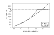
- FIG. 11A is a diagram showing a first example of the relationship between the refractory temperature and the distance in the thickness direction of the refractory.
- FIG. 11B is a diagram showing a second example of the relationship between the refractory temperature and the distance in the thickness direction of the refractory.
- FIG. 12 is a diagram illustrating an example of a hardware configuration of an equipment state monitoring device.
- the equipment status monitoring device 100 of this embodiment monitors the condition of the inner circumferential surface of the side wall of the equipment in which molten metal exists during operation.
- the inner circumferential surface of the side wall of the equipment is the surface that contacts the space in which molten metal may exist (for example, the surface facing the central axis (center line) side of the equipment).
- the inner circumferential surface of the side wall of the equipment is made of refractory material.
- an arc melting furnace which is a type of electric furnace, is exemplified as such equipment.
- the equipment monitored by the equipment status monitoring device 100 is not limited. In an arc melting furnace, raw materials such as scrap are charged into the furnace for each charge (ch).
- the raw materials are then melted and fused by an arc generated from the arc electrode.
- molten metal for example, molten steel
- molten slag the period from the timing when the raw materials are charged into the furnace to the timing when the molten metal and molten slag are discharged outside the furnace is called a charge.
- the side wall of the arc melting furnace is exposed to high temperatures. Therefore, refractory materials such as firebricks are used to construct the side walls of the arc melting furnace.
- the equipment monitored by the equipment status monitoring device 100 is not limited to arc melting furnaces.
- the equipment monitored by the equipment status monitoring device 100 may be an electric furnace other than an arc melting furnace, or an industrial furnace such as a blast furnace or converter.
- Fig. 1 is a diagram showing an example of the configuration of an electric furnace 1.
- Fig. 1 is a vertical cross-sectional view of the electric furnace 1.
- this embodiment illustrates an electric furnace 1 including an upper lid 2, arc electrodes 3a to 3c, a furnace bottom electrode 4, a furnace bottom portion 5, and a side wall portion 6.
- Fig. 1 illustrates an example in which the electric furnace 1 includes three arc electrodes 3a to 3c.
- Fig. 1 also illustrates an example in which the three arc electrodes 3a to 3c are installed at equal intervals (120° intervals) around the central axis (center line) O of the electric furnace 1.
- the direction around the central axis (center line) O of the electric furnace 1 will be referred to as the circumferential direction as necessary.
- the central axis (center line) O of the electric furnace 1 will be abbreviated to the central axis O as necessary.
- FIG. 1 illustrates an example in which the side wall portion 6 is disposed so as to surround the central axis O.
- FIG. 1 illustrates an example in which the side wall portion 6 includes wear bricks 7, permanent bricks 8, precast blocks 9, and an iron shell 10. Refractory bricks are used to form the wear bricks 7. Of the faces of the wear bricks 7, the face facing the central axis O forms the inner circumferential surface 6a of the side wall portion 6 of the electric furnace 1.
- the inner circumferential surface 6a side of the side wall portion 6 of the electric furnace 1 will be referred to as the inner side as necessary.
- the inner side is the side closer to the central axis O of the electric furnace 1.
- the side opposite the inner side will be referred to as the outer side as necessary.
- the outer side is the outer circumferential surface 6b side of the side wall portion 6 of the electric furnace 1 (the side farther from the central axis O of the electric furnace 1).
- Firebricks are used to form the permanent bricks 8.
- the permanent bricks 8 are installed outside the wear bricks 7.
- the outer end of the wear brick 7 and the inner end of the permanent brick 8 are connected (fixed) to each other, for example, via a material having heat resistance and adhesive properties.
- the material having heat resistance and adhesive properties is, for example, mortar.
- the shell 10 is placed outside the permanent bricks 8.
- the shell 10 constitutes the outer peripheral surface 6b of the side wall portion 6 of the electric furnace 1.
- the inner end of the shell 10 and the outer end of the permanent bricks 8 are connected (fixed) to each other, for example, via a material that is heat-resistant and adhesive.
- the heat-resistant and adhesive material is, for example, mortar.
- the above electric furnace configuration is that of a general electric furnace.
- the configuration of an electric furnace is not limited to that of the above electric furnace.
- a precast block 9 is installed in a part of the area where the permanent bricks 8 are installed in such a general electric furnace.
- the precast block 9 is an example of a precast refractory block. As described later, this embodiment illustrates a case in which the precast block 9 is produced by precasting an amorphous refractory with the optical fiber of the optical fiber temperature sensor embedded in it.
- the temperature distribution of the side wall 6 in an imaginary plane parallel to the inner circumferential surface 6a has a local maximum value (local maximum value).
- local maximum value such a position where the temperature is locally maximum will be referred to as a hot spot as necessary.
- an electric furnace arc melting furnace
- the precast block 9 is installed so as to satisfy all of the following (A) to (D).
- (A) The position of the outer end of the precast block 9 is the same as the outer end of the permanent brick 8, or is more inward than the outer end of the permanent brick 8.
- (B) The position of the inner end of the precast block 9 is the same as the inner end of the permanent brick 8, or is further outboard than the inner end of the permanent brick 8.
- the circumferential position of the precast block 9 includes the circumferential position of the area where hot spots are expected to occur.
- (D) The height position of the precast block 9 includes the height position of the area where hot spots are expected to occur.
- the precast block 9 is used to install a temperature sensor in the side wall 6 for measuring the temperature of the side wall 6.
- an optical fiber temperature sensor is used as a temperature sensor for measuring the temperature of the side wall 6.
- the optical fiber temperature sensors 111-112 include optical fibers 121-122 and measuring instruments 131-132.
- the measuring instruments 131-132 output light (e.g., infrared light) into the optical fibers 121-122.
- the light output into the optical fibers 121-122 is scattered within the optical fibers 121-122.
- the measuring instruments 131-132 input the light that is scattered within the optical fibers 121-122 and returns.
- the measuring instruments 131-132 calculate the temperature at each position within the optical fibers 121-122 based on the intensity, speed, and time of the input and output light.
- the optical fiber temperature sensors 111-112 themselves are realized using known technology, so a detailed description of the optical fiber temperature sensors 111-112 will be omitted here.
- Optical fibers 121-122 are embedded in the precast block 9.
- the optical fiber 121 is installed at a relatively inner position so that both the temperature distribution in the height direction of the side wall 6 and the temperature distribution in the circumferential direction of the side wall 6 can be measured.
- the optical fiber 122 is installed at a relatively outer position so that both the temperature distribution in the height direction of the side wall 6 and the temperature distribution in the circumferential direction of the side wall 6 can be measured.
- the optical fiber installed at a relatively inner position is referred to as the inner optical fiber as necessary.
- the optical fiber installed at a relatively outer position is referred to as the outer optical fiber as necessary.
- the height direction of the side wall 6 and the circumferential direction of the side wall 6 are abbreviated to the height direction and the circumferential direction, respectively, as necessary.
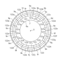
- FIG. 2 is a cross-sectional view taken along line I-I in FIG. 1. For ease of illustration and explanation, hatching showing a cut surface is omitted in FIG. 2 as well.
- the electric furnace 1 is provided with a plurality of precast blocks 9a-9r.
- the plurality of precast blocks 9a-9r are arranged in the circumferential direction of the electric furnace 1.
- the plurality of precast blocks 9a-9r have the same configuration.
- the shape and size of at least one of the plurality of precast blocks 9a-9r may be different from the other precast blocks.
- At least one physical property value (i.e., the material constituting the precast block) of the plurality of precast blocks 9a-9r may also be different from the other precast blocks.
- the physical property values of the plurality of precast blocks 9a-9r are substantially the same, and it is more preferable that they are the same. This is because there is no need to change the physical property values of the precast blocks used in performing the three-dimensional unsteady heat transfer inverse problem analysis described later depending on the location.
- the circumferential ends of two adjacent precast blocks (e.g., precast blocks 9a to 9b) among the precast blocks 9a to 9r are connected (fixed) to each other, for example, via a heat-resistant and adhesive material.
- the outer end of the wear brick 7 and the inner end of the precast blocks 9a to 9r are also connected (fixed) to each other, for example, via a heat-resistant and adhesive material.
- the inner end of the steel shell 10 and the outer end of the precast blocks 9a to 9r are also connected (fixed) to each other, for example, via a heat-resistant and adhesive material.
- the material (heat-resistant and adhesive material) for connecting (fixing) the precast blocks 9a to 9r in this manner is, for example, mortar.
- this embodiment illustrates a case where inner optical fibers 121a to 121r and outer optical fibers 122a to 122r are installed in each precast block 9a to 9r.
- This embodiment also illustrates a case where the inner optical fibers 121 to 121r have the same configuration.
- This embodiment also illustrates a case where the outer optical fibers 122a to 122r have the same configuration.
- This embodiment also illustrates a case where the inner optical fibers 121 to 121r and the outer optical fibers 122a to 122r are relatively arranged in the same manner in each precast block 9a to 9r.
- this embodiment illustrates a case where the precast blocks 9a to 9r have the same configuration.
- each precast block 9a to 9r in a relative coordinate system with the reference position (for example, the position of the center of gravity) of each precast block 9a to 9r as the origin, the coordinates of the positions where the inner optical fibers 121a to 121r and the outer optical fibers 122a to 122r exist are the same. That is, in this embodiment, the precast blocks 9a to 9r have the same configuration, including the inner optical fibers 121a to 121r and the outer optical fibers 122a to 122r. In addition, this embodiment illustrates a case where even if at least two of the precast blocks 9a to 9r are replaced, the state before the replacement is the same.
- the precast block 9 shown in FIG. 1 is one of the precast blocks 9a to 9r.
- the reference symbol 9 is used for the precast block.
- the inner optical fiber 121 and the outer optical fiber 122 shown in FIG. 1 are each one of the inner optical fibers 121a to 121r and the outer optical fibers 122a to 122r.
- the reference symbols 121 and 122 are used for the inner optical fiber and the outer optical fiber, respectively.
- FIG. 3 is a diagram showing an example of the configuration of a precast block 9 in which an inner optical fiber 121 and an outer optical fiber 122 are embedded.
- the inner optical fiber 121 is disposed relatively inside, and the outer optical fiber 122 is disposed relatively outside.
- the inner optical fiber 121 is disposed so as to meander on a virtual plane 31a with the circumferential direction as the traveling direction.
- the virtual plane 31a is a plane parallel to the inner circumferential surface 6a of the side wall portion 6.
- the outer optical fiber 122 is disposed so as to meander on the imaginary plane 31b with the circumferential direction as the traveling direction.
- the imaginary plane 31b is a plane parallel to the inner circumferential surface 6a of the side wall portion 6.
- the shape of the precast block 9 is shown as a rectangular column with a hollow fan-shaped bottom.
- the shape of the precast block 9 is not limited to this shape.
- the shape of the precast block 9 may be a rectangular parallelepiped.
- both ends of the inner optical fiber 121 and the outer optical fiber 122 are pulled out to the outside of the precast block 9.
- the inner optical fibers 121a to 121r are connected in series.
- the outer optical fibers 122a to 122r are also connected in series.
- One end of the inner optical fibers 121a to 121r connected in series is connected to the measuring device 131 shown in FIG. 1.
- the other end of the inner optical fibers 121a to 121r connected in series may be embedded in the precast block 9 or may be pulled out to the outside of the precast block 9.
- One end of the outer optical fibers 122a to 122r connected in series is connected to the measuring device 132 shown in FIG. 1.
- the other end of the outer optical fibers 122a to 122r connected in series may be embedded in the precast block 9 or may be pulled out to the outside of the precast block 9.
- the end pulled out from the right side is connected to the two ends of the inner optical fiber 121 embedded in the precast block 9 adjacent to the right side of the precast block 9, which is pulled out from the left side.
- the end pulled out from the right side is connected to the two ends of the inner optical fiber 121b embedded in the precast block 9b adjacent to the right side of the precast block 9a, which is pulled out from the left side.
- the end pulled out from the left side is connected to the two ends of the inner optical fiber 121 embedded in the precast block 9 adjacent to the left side of the precast block 9, which is pulled out from the right side.
- the end pulled out from the left side is connected to the two ends of the inner optical fiber 121r embedded in the precast block 9r adjacent to the left side of the precast block 9a, which is pulled out from the right side.
- the inner optical fibers 121a to 121r are installed so as to surround the central axis O of the electric furnace 1 while meandering in the circumferential direction on the imaginary plane 31a.
- the end pulled out from the right side is connected to the two ends of the outer optical fiber 122 embedded in the precast block 9 adjacent to the right side of the precast block 9, which is pulled out from the left side.
- the end pulled out from the right side is connected to the two ends of the outer optical fiber 122b embedded in the precast block 9b adjacent to the right side of the precast block 9a, which is pulled out from the left side.
- the end pulled out from the left side is connected to the two ends of the outer optical fiber 122 embedded in the precast block 9 adjacent to the left side of the precast block 9, which is pulled out from the right side.
- the end pulled out from the left side is connected to the two ends of the outer optical fiber 122r embedded in the precast block 9r adjacent to the left side of the precast block 9a, which is pulled out from the right side.
- the outer optical fibers 122a to 122r are installed so as to surround the central axis O of the electric furnace 1 while meandering in the circumferential direction on the imaginary plane 31b.
- the optical fiber temperature sensor 111 that measures the temperature at a relatively inner position and the optical fiber temperature sensor 112 that measures the temperature at a relatively outer position are illustrated as separate temperature sensors.
- a single optical fiber temperature sensor may measure both the temperature at a relatively inner position and the temperature at a relatively outer position.
- a single optical fiber may be installed in the installation area of the optical fibers 121 and 122.
- the precast block 9 is manufactured, for example, as follows.
- the amorphous refractory is placed in a form having a shape and size according to the outer shape of the precast block 9.
- the inner optical fiber 121 and the outer optical fiber 122 are placed in the form so as to be embedded in the above-mentioned position in the precast block 9.
- the amorphous refractory is hardened (dried) in a state in which the inner optical fiber 121 and the outer optical fiber 122 are placed in the form.
- the positions (coordinates of the above-mentioned relative coordinate system) of the inner optical fiber 121 and the outer optical fiber 122 in the precast block 9 are specified even in a state in which they are embedded in the precast block 9.
- a jig (not shown) that holds the inner optical fiber 121 and the outer optical fiber 122 outside the form
- a jig having a configuration capable of adjusting the position of the object to be held within the formwork may be used.
- the inner optical fiber 121 and the outer optical fiber 122 are placed within the formwork while attached to such a jig.
- the jig is then adjusted to set the inner optical fiber 121 and the outer optical fiber 122 to predetermined positions within the formwork.
- the jig then maintains the positions of the inner optical fiber 121 and the outer optical fiber 122 within the precast block 9 until the amorphous refractory hardens.
- the castable refractory material may be placed in the formwork.
- a material for the amorphous refractory material a material is used such that the mechanical strength of the precast block 9 has the mechanical strength required for the side wall portion 6 and the heat resistance of the precast block 9 satisfies the heat resistance required for the side wall portion 6.
- the lengths of the inner optical fiber 121 and the outer optical fiber 122 pulled out from the precast block 9 can be determined even when they are embedded in the precast block 9. Therefore, once the positions of the inner optical fiber 121 and the outer optical fiber 122 within the precast block 9 are determined, the lengths from the measuring devices 131-132 to the positions of the inner optical fiber 121 and the outer optical fiber 122 can also be determined.
- the inner optical fiber and the outer optical fiber e.g., the inner optical fiber 121a and the outer optical fiber 122a
- the inner optical fiber and the outer optical fiber that are in the same circumferential position may be embedded in different precast blocks.
- the inner optical fiber and the outer optical fiber e.g., the inner optical fiber 121a and the outer optical fiber 122a
- the circumferential positions of the inner optical fiber and the outer optical fiber do not have to be the same.
- a temperature sensor other than the optical fiber temperature sensor may be used instead of the optical fiber temperature sensor 112 .
- the temperature sensor other than the optical fiber temperature sensor does not need to be embedded in the side wall portion 6.
- the temperature sensor other than the optical fiber temperature sensor may be, for example, a temperature sensor that measures the temperature distribution on the outer surface of the iron shell 10.
- Such a temperature sensor may be a radiation thermometer or a thermocouple.
- such a temperature sensor is installed at a position outside the optical fiber temperature sensor (optical fiber) so that it can measure both the temperature distribution in the height direction of the side wall portion 6 and the temperature distribution in the circumferential direction of the side wall portion 6.
- such a temperature sensor is installed at a position where it can measure the temperature in the area where the aforementioned hot spot is expected to occur.
- a permanent brick may be installed outside the permanent brick 8.
- the precast block 9 in which the inner optical fiber 121 and the outer optical fiber 122 are embedded is preferably installed in a part of the area in which the permanent brick 8 closest to the steel shell 10 is installed.
- the precast block 9 in which the inner optical fiber 121 and the outer optical fiber 122 are embedded is easily installed and maintained.
- the precast block 9 in which the inner optical fiber 121 and the outer optical fiber 122 are embedded may be installed in a part of the area in which the permanent brick other than the permanent brick closest to the steel shell 10 is installed.
- the wear brick 7 constitutes the inner peripheral surface 6a of the side wall portion 6 of the electric furnace 1.
- the precast block 9 in which the inner optical fiber 121 and the outer optical fiber 122 are embedded does not constitute the inner peripheral surface 6a of the side wall portion 6 of the electric furnace 1.
- the precast block 9 in which the inner optical fiber 121 and the outer optical fiber 122 are embedded is not installed in the area in which the wear bricks 7 are installed.
- the precast block 9 in which the inner optical fiber 121 and the outer optical fiber 122 are embedded is installed, for example, in the area in which the permanent bricks, which are refractory materials that do not constitute the inner circumferential surface 6a of the side wall portion 6 of the electric furnace 1, are installed.
- the equipment status monitoring device 100 of this embodiment calculates the temperature distribution in the thickness direction of the side wall portion 6 by performing a three-dimensional unsteady heat transfer inverse problem analysis based on the measured values of the optical fiber temperature sensors 111-112.
- the temperature distribution in the thickness direction of the side wall portion 6 is information indicating the relationship between the position in the thickness direction of the side wall portion 6 and the temperature of the side wall portion 6.
- the equipment status monitoring device 100 may also calculate the temperature distribution in other directions (for example, the height direction and the circumferential direction).
- the temperature distribution in the thickness direction of the side wall portion 6 is calculated in a range assumed as a range in which the inner circumferential surface 6a of the side wall portion 6 may exist. That is, the temperature distribution in the thickness direction of the side wall portion 6 may include the temperature of the region inside the furnace in addition to the region where the side wall portion 6 actually exists.
- the equipment status monitoring device 100 calculates the position of the inner circumferential surface 6a based on the temperature distribution in the thickness direction of the side wall portion 6.
- the position of the inner circumferential surface 6a calculated by the equipment status monitoring device 100 includes the position in the thickness direction of the side wall portion 6.
- the thickness direction of the side wall portion 6 is the direction in which a straight line connecting the inner circumferential surface 6a and the outer circumferential surface 6b at the shortest distance extends (the radial direction of the electric furnace 1).
- the position in the thickness direction of the side wall portion 6 is represented, for example, by the value of the coordinate axis when the straight line is used as the coordinate axis. In the following description, the thickness direction of the side wall portion 6 will be abbreviated to thickness direction as necessary.
- the term "unsteady heat transfer inverse problem” refers to a problem based on the unsteady heat conduction equation governing the calculation domain, in which the temperature information inside the domain is known and at least one of the boundary conditions of the physical quantities (temperature, heat flux, etc.) at the domain boundary and the initial conditions of the physical quantities at the domain boundary is estimated.
- the unsteady heat transfer inverse problem is a problem of estimating the temperature at the domain boundary (the temperature of the inner circumferential surface 6a).
- the unsteady heat transfer forward problem refers to a problem of estimating the temperature information inside the domain based on known boundary conditions.
- Patent Document 1 discloses solving a one-dimensional unsteady heat transfer inverse problem.
- a one-dimensional unsteady heat transfer inverse problem it is not possible to sufficiently improve the estimation accuracy of the temperature distribution in the thickness direction of the side wall portion 6. This will be explained with reference to Figures 4A, 4B, 5A, and 5B.
- Figures 4A and 4B are diagrams explaining an example of heat transfer that can be considered in a one-dimensional unsteady heat transfer inverse problem.
- Figures 5A and 5B are diagrams explaining an example of heat transfer that can be considered in a three-dimensional unsteady heat transfer inverse problem.
- a three-dimensional unsteady heat transfer inverse problem is exemplified in a three-dimensional Cartesian coordinate system (x-y-z coordinate system). Therefore, x-y-z coordinates are shown in each figure.
- the origin of the x-y-z coordinates shown in each figure is not limited to the position shown in each figure.
- a symbol with a black circle inside a white circle indicates an arrow line going from the back of the paper to the front (the coordinate axis with the positive direction going from the back of the paper to the front).
- the x-axis direction corresponds to the thickness direction.
- the y-axis direction corresponds to the circumferential direction.
- the z-axis direction corresponds to the height direction.
- the inner circumferential surface 6a of the side wall portion 6 is not a flat surface. Therefore, in this embodiment, the circumferential direction and height direction of the side wall portion 6 that appears as a flat surface by cutting the side wall portion 6 along the height direction at one point in the circumferential direction and developing it are respectively set as the y-axis direction and the z-axis direction, and the y-coordinate and z-coordinate of each position of the side wall portion 6 are determined.
- the y-coordinate and z-coordinate of each position of the side wall portion 6 are determined in the same manner as for the inner circumferential surface 6a for surfaces (virtual surfaces 31a, 31b, etc.) parallel to the inner circumferential surface 6a.
- the heat flux is from the inside, where the temperature is high, to the outside.
- the temperature distribution in the thickness direction of the side wall 6 is calculated assuming that the heat transfer occurs only in the thickness direction (x-axis direction) of the side wall 6.
- thermo measurement positions 41a-41b, 41c-41d, 41e-41f, 41g-41h, 41i-41j, and 41k-41l are aligned in the thickness direction of the side wall portion 6.
- the direction of heat transfer that can be considered in the unsteady heat transfer inverse problem is limited to the direction in which temperature measurement positions 41a-41b, 41c-41d, 41e-41f, 41g-41h, 41i-41j, and 41k-41l are aligned (the direction along the arrow line shown in Figures 4A and 4B).
- the actual direction of heat transfer is not limited to the thickness direction (x-axis direction) of the side wall 6.
- the direction of heat transfer is limited to the thickness direction of the side wall 6. For this reason, even if the number of temperature measurement positions is increased, there is a limit to improving the accuracy of estimating the temperature distribution in the thickness direction of the side wall 6.
- the direction of heat transfer is limited to the thickness direction of the side wall 6 and only one of the circumferential and height directions of the side wall 6.
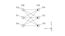
- the direction of heat transfer that can be taken into account in the unsteady heat transfer inverse problem is not limited to the direction in which the temperature measurement positions 51a to 51b, 51c to 51d, 51e to 51f, 51g to 51h, 51i to 51j, and 51k to 41l are aligned.
- the direction of heat transfer that can be considered in the inverse problem of unsteady heat transfer is each direction from any one of the temperature measurement positions 51a, 51c, 51e, 51g, 51i, and 51k on the inside to any one of the temperature measurement positions 51b, 51d, 51f, 51h, 51j, and 51l on the outside (direction along the arrow line shown in FIG. 5A and FIG. 5B).
- all directions including the thickness direction of the side wall portion 6, the circumferential direction of the side wall portion 6, and the height direction of the side wall portion 6 can be considered.
- the estimation accuracy of the temperature distribution in the thickness direction of the side wall portion 6 can be improved. This can improve the estimation accuracy of the position in the thickness direction of the inner circumferential surface 6a. Therefore, in this embodiment, a three-dimensional unsteady heat transfer inverse problem analysis is performed to calculate the temperature distribution in the thickness direction of the side wall portion 6.
- thermocouples as temperature sensors as described in Patent Document 1
- optical fiber temperature sensors 111 and 112 are used as temperature sensors.
- the temperature measurement position is between a wear brick 7 and a permanent brick 8, or between individual permanent bricks 8, there is a risk that the measurement accuracy of the temperature measured at that temperature measurement position will be lower than the measurement accuracy of the temperature measured at other temperature measurement positions. This is because the temperature measured at that temperature measurement position is affected by the properties and gaps around that temperature measurement position (temperature sensor). Therefore, there is a risk that the accuracy of the temperature measured by the temperature sensor will vary depending on the temperature measurement position. On the other hand, if the physical property values around the temperature sensor are approximately the same (preferably the same), such temperature variation can be suppressed. Furthermore, burying a temperature sensor in a brick increases the workload.
- the temperature sensor is embedded in a precast block 9 that has approximately the same physical property values (preferably the same physical property values).
- the temperature sensor does not necessarily have to be embedded in the precast block 9.
- optical fiber temperature sensors 111-112 may be embedded in the permanent brick 8. In this case, it is preferable to use only positions inside the permanent brick 8 as temperature measurement positions.
- the precast block 9 does not have to be installed in the electric furnace 1.
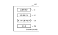
- FIG. 6 is a diagram showing an example of the functional configuration of the equipment status monitoring device 100.
- the equipment status monitoring device 100 has, for example, one or more hardware processors such as a CPU (Central Processing Unit) and one or more memories such as a RAM (Random Access Memory) and a ROM (Read Only Memory) as hardware.
- the equipment status monitoring device 100 executes various calculations by executing one or more programs stored in the memory by one or more hardware processors.
- the equipment status monitoring device 100 has an input device and an output device as hardware. At least one of the input device and the output device may be outside the equipment status monitoring device 100. In this case, the equipment status monitoring device 100 performs wired communication or wireless communication with the input device and the output device.
- the equipment status monitoring device 100 includes a temperature acquisition unit 61, an inverse problem analysis unit 62, a refractory position calculation unit 63, and an output unit 64.
- a temperature acquisition unit 61 the equipment status monitoring device 100 includes a temperature acquisition unit 61, an inverse problem analysis unit 62, a refractory position calculation unit 63, and an output unit 64.
- An example of the function of each unit is described below. Note that information that can be set in advance in the calculations described below is stored in the equipment status monitoring device 100 via an input device, for example.
- the temperature acquisition unit 61 acquires the measured values of the optical fiber temperature sensors 111 to 112. As described above, in this embodiment, the temperature at each position in the optical fibers 121 to 122 is calculated by the measuring instruments 131 to 132. Therefore, in this embodiment, the temperature acquisition unit 61 acquires the temperatures at each position in the optical fibers 121 to 122 calculated by the measuring instruments 131 to 132 as the measured values of the optical fiber temperature sensors 111 to 112.
- the temperature acquisition unit 61 may acquire the measured values of the optical fiber temperature sensors 111 to 112 by performing wired or wireless communication with the measuring instruments 131 to 132. Furthermore, the temperature acquisition unit 61 may acquire the measured values of the optical fiber temperature sensors 111 to 112 via devices other than the measuring instruments 131 to 132. Furthermore, the temperature acquisition unit 61 may have the functions of the measuring instruments 131 to 132.
- the positions at which the measurement values of the optical fiber temperature sensors 111-112 are obtained are set in advance from among the positions within the optical fibers 121-122. It is preferable that the positions at which the measurement values of the optical fiber temperature sensors 111-112 are obtained are as wide-ranging and as numerous as possible. This is because the accuracy of calculating the temperature at the temperature acquisition positions (hotspot center of gravity position, hotspot peripheral positions) described below is improved. However, if there are too many positions at which the measurement values of the optical fiber temperature sensors 111-112 are obtained, there is a risk that the calculation load will become too high. Therefore, it is preferable that the positions at which the measurement values of the optical fiber temperature sensors 111-112 are obtained are set in advance from the viewpoint of balancing between reducing the calculation load and improving the calculation accuracy.
- the temperature acquisition unit 61 may acquire measurements during charging as the measurements of the optical fiber temperature sensors 111-112. In this way, the equipment status monitoring device 100 can calculate the position in the thickness direction of the inner circumferential surface 6a even when the state of the inner circumferential surface 6a of the side wall portion 6 cannot be measured by a profile meter or the like due to the presence of raw materials in the furnace.
- the timing at which the temperature acquisition unit 61 acquires the measurements of the optical fiber temperature sensors 111-112 is not limited to such timing.
- the temperature acquisition unit 61 may acquire measurements between charges as the measurements of the optical fiber temperature sensors 111-112. The period between charges is, for example, the period from when the molten metal and molten slag are discharged out of the furnace to when the next raw materials are inserted.
- the optical fiber temperature sensors 111-112 measure the temperature at each position in the optical fibers 121-122 at a constant time period. Also, in this embodiment, an example is shown in which the temperature acquisition unit 61 acquires the measurement values of the optical fiber temperature sensors 111-112 at each time period. In the following description, the time period in which the temperature acquisition unit 61 acquires the measurement values of the optical fiber temperature sensors 111-112 is referred to as the temperature measurement period, as necessary.
- the inverse problem analysis unit 62 performs a three-dimensional unsteady heat transfer inverse problem analysis based on the measured values of the optical fiber temperature sensors 111 to 112, thereby calculating the temperature distribution in the thickness direction (x-axis direction) of the side wall portion 6.
- N temperatures can be used at one location in the thickness direction of the side wall portion 6 as the temperature for calculating one position in the thickness direction of the inner circumferential surface 6a. This embodiment illustrates such a case.
- N is an integer of 2 or more.
- N is preferably an integer of 3 or more, and more preferably 5 (this will be described later).
- the accuracy of estimating the position in the thickness direction of the inner circumferential surface 6a can satisfy the accuracy required in practice (can be brought close to the actual measured value) (see the calculation example described later ( Figure 11)).
- the inverse problem analysis unit 62 acquires five temperatures per location in the thickness direction of the side wall 6 as temperatures for calculating one position in the thickness direction of the inner surface 6a based on the measured values of the optical fiber temperature sensors 111-112, and performs three-dimensional unsteady heat transfer inverse problem analysis based on the acquired temperatures.
- the five temperatures acquired by the inverse problem analysis unit 62 at one location in the thickness direction of the side wall 6 may be the measured values of the optical fiber temperature sensors 111-112, or may be temperatures calculated based on the measured values of the optical fiber temperature sensors 111-112. As described above, it is preferable that the number of temperatures acquired by the inverse problem analysis unit 62 at one location in the thickness direction of the side wall 6 is five. However, the number of temperatures acquired by the inverse problem analysis unit 62 at one location in the thickness direction of the side wall 6 is not limited to five, and may be, for example, a number greater than five.
- the number of temperatures acquired by the inverse problem analysis unit 62 at one location in the thickness direction of the side wall 6 is too large, a large number of measured values are required as the measured values of the temperatures.
- the calculation accuracy of the weighting coefficients w i, j, k, and l of the equation (3) described below, which are calculated by performing a three-dimensional unsteady heat transfer inverse problem analysis, will decrease (specifically, overfitting will occur). Therefore, it is preferable to set the number of temperatures acquired by the inverse problem analysis unit 62 in consideration of these points.
- a hot spot is a position where the temperature is locally maximum.
- a hot spot region is a region that includes a hot spot. In this embodiment, a case is illustrated in which a hot spot region is defined in each of the x coordinates of the installation regions (regions within the virtual planes 31a and 31b) of the optical fibers 121 and 122.
- the temperature distribution in the installation area of the optical fibers 121, 122 (area within the virtual surfaces 31a, 31b) is shown on the y-z plane.
- the temperature distribution shown in Figure 7 is calculated based on the measurement values of the optical fiber temperature sensors 111-112.
- the temperature distribution shown in Figure 7 is calculated by interpolating the measurement values of the optical fiber temperature sensors 111-112.
- the method of interpolation is not limited, and may be any known method such as linear approximation, spline interpolation, polynomial interpolation, etc.
- the position may be determined as the position of the hotspot area.
- the temperature of the position may be determined as the temperature of the hotspot area.
- the hotspot area may be searched for in each of a plurality of temperature divisions obtained by dividing the temperature range measurable by the optical fibers 121 and 122 into a plurality of divisions.
- the area of the temperature division showing the highest temperature among the plurality of temperature divisions may be determined as the hotspot area.
- the representative position of the hotspot area may be determined as the position of the hotspot area, and the temperature of the position may be determined as the temperature of the hotspot area.
- the case where the area of the temperature division of 500°C to 525°C is the hotspot area 71 is illustrated as an example.
- the representative position of the hotspot area 71 is, for example, the position of the center of gravity of the hotspot area 71.
- the inverse problem analysis unit 62 calculates the temperature of the hotspot region 71 for the entire installation area (area within virtual planes 31a, 31b) of the optical fibers 121, 122 based on the measured values of the optical fiber temperature sensors 111-112. In this case, the temperature of the hotspot region 71 is one of the five temperatures described above. If there are multiple hotspot regions 71 in the installation area (area within virtual planes 31a, 31b) of the optical fibers 121, 122, the temperature of each hotspot region 71 is one of the five temperatures described above.
- the inverse problem analysis unit 62 calculates the temperature of the hotspot region 71 in the installation area of the optical fibers 121 and 122 as follows.
- the inverse problem analysis unit 62 may match the y-z coordinates of the representative positions of the hotspot region 71 in the installation area of the optical fibers 121 and 122, and to calculate the temperature of the matched y-z coordinate as the temperature of the hotspot region 71 in the installation area of the optical fibers 121 and 122.
- the inverse problem analysis unit 62 may take the arithmetic average values of the y and z coordinates of the hotspot region 71 in the installation area of the optical fibers 121 and 122 as the y and z coordinates of each hotspot region 71.
- the inverse problem analysis unit 62 may set one of the y coordinates and z coordinates of the hotspot region 71 in the installation region of the optical fibers 121 and 122 to the other y coordinate and z coordinate.
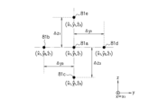
- FIG. 8A and 8B are diagrams showing an example of the positions of temperatures acquired when performing a three-dimensional unsteady heat transfer inverse problem analysis.
- the position of the hotspot region 71 is referred to as the hotspot centroid position as necessary.
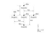
- FIG. 8A shows an example of five temperature positions 81a to 81e obtained in the installation area (area within imaginary plane 31a) of the inner optical fiber 121.
- FIG. 8B shows an example of five temperature positions 82a to 82e obtained in the installation area (area within imaginary plane 31b) of the outer optical fiber 122.
- the coordinate values of the hotspot centroid position 81a in the installation area of the inner optical fiber 121 are (x ⁇ 1 , y ⁇ 1 , z ⁇ 1 ).
- x ⁇ , y ⁇ , and z ⁇ correspond to the symbols with ⁇ above x, y, and z, respectively, in the mathematical expressions described below.
- a case is illustrated in which four positions 81b to 81e are determined around the hotspot centroid position 81a on the y-z plane at the x coordinate position x1 .
- the coordinate values of the positions 81b, 81c, 81d, and 81e are (x ⁇ 1 , y ⁇ 0 , z ⁇ 1 ), (x ⁇ 1 , y ⁇ 1 , z ⁇ 0 ), (x ⁇ 1 , y ⁇ 2 , z ⁇ 1 ), and (x ⁇ 1 , y ⁇ 1 , z ⁇ 2 ), respectively.
- FIG. 8A illustrates an example in which only two of the four positions 81b-81e surrounding the hotspot center of gravity position 81a (e.g., positions 81b and 81d) are located on the same straight line.
- the coordinate values of the hotspot centroid position 82a in the installation area of the outer optical fiber 122 are ( x2 , y1 , z1 ).
- this embodiment illustrates a case in which four positions 82b to 82e are defined around the hotspot centroid position 82a on the y-z plane at the x-coordinate position of x2.
- the coordinate values of the positions 82b, 82c, 82d, and 82e are (x ⁇ 2 , y ⁇ 0 , z ⁇ 1 ), (x ⁇ 2 , y ⁇ 1 , z ⁇ 0 ), (x ⁇ 2 , y ⁇ 2 , z ⁇ 1 ), and (x ⁇ 2 , y ⁇ 1 , z ⁇ 2 ), respectively.
- the distances ⁇ y 1 , ⁇ y 2 , ⁇ z 1 , and ⁇ z 2 in the y-axis direction and z-axis direction from the hotspot centroid positions 81a, 82a to the four positions 81b to 81e, 82b to 82e around the hotspot centroid positions 81a, 82a are set before performing a three-dimensional unsteady heat transfer inverse problem analysis.
- the four positions around the hotspot centroid positions 81a, 82a are referred to as hotspot peripheral positions as necessary.
- the distances ⁇ y 1 , ⁇ y 2 , ⁇ z 1 , and ⁇ z 2 in the y-axis direction and z-axis direction from the hotspot centroid positions 81a, 82a to the hotspot peripheral positions 81b to 81e, 82b to 82e are abbreviated as distances ⁇ y 1 , ⁇ y 2 , ⁇ z 1 , and ⁇ z 2 as necessary.
- the distances ⁇ y1 , ⁇ y2 , ⁇ z1 , and ⁇ z2 are not limited as long as the calculation accuracy of the position in the thickness direction of the inner circumferential surface 6a, which is calculated, for example, as described below, is determined so as to satisfy the accuracy required for practical use.
- distances ⁇ y 1 , ⁇ y 2 , ⁇ z 1 , and ⁇ z 2 that satisfy the accuracy required for practical use of the calculation accuracy of the position in the thickness direction of the inner circumferential surface 6a may be searched for by trial and error.
- a test furnace simulating an electric furnace 1 is subjected to a three-dimensional unsteady heat transfer inverse problem analysis described later to calculate the position in the thickness direction of the inner circumferential surface 6a, with the distances ⁇ y 1 , ⁇ y 2 , ⁇ z 1 , and ⁇ z 2 being different.
- the calculated values of the positions in the thickness direction of the inner circumferential surface 6a at the respective distances ⁇ y 1 , ⁇ y 2 , ⁇ z 1 , and ⁇ z 2 are compared with the actual measured values in the test furnace. Finally, based on the result of this comparison, distances ⁇ y 1 , ⁇ y 2 , ⁇ z 1 , and ⁇ z 2 that satisfy the accuracy required for practical use of the calculation accuracy of the position in the thickness direction of the inner circumferential surface 6a are searched for.
- the wear brick 7 at the position intersecting the virtual line connecting the hotspot centroid positions 81a, 82a and the central axis O of the electric furnace 1 at the shortest distance may be worn out.
- the wear brick 7 is worn out like this, the region of the inner circumferential surface 6a where the wear brick 7 is located is recessed more than the other regions. In this case, it is preferable to determine the distances ⁇ y 1 , ⁇ y 2 , ⁇ z 1 , and ⁇ z 2 based on the size of the recessed portion.
- the portion of the inner circumferential surface 6a recessed due to the wear of the wear brick 7 is referred to as a worn portion as necessary.
- the wear of the wear brick 7 occurs due to melting or peeling of the wear brick 7.
- FIGS. 9A and 9B are diagrams showing an example of a worn portion.
- FIG. 9A is a diagram showing an example of a region including a worn portion when the side wall portion 6 is viewed from above.
- FIG. 9B is a diagram showing an example of a region including a worn portion when the side wall portion 6 is viewed from the central axis O side of the electric furnace 1.
- FIGS. 9A and 9B show a state that is assumed when the side wall portion 6 is cut along the height direction at one point in the circumferential direction and unfolded.
- FIGS. 9A and 9B show only a portion of the side wall portion 6 (a region corresponding to one precast block 9). Note that hatching showing the cut surface is omitted in FIGS. 9A and 9B as well for convenience of notation and explanation.
- the wear brick 7 on which the damaged portion 92 is formed is the wear brick 7 located at the intersection with the imaginary line 91 that connects the hotspot center of gravity positions 81a, 82a and the central axis O of the electric furnace 1 in the shortest distance.
- the distances ⁇ y 1 and ⁇ y 2 are determined based on, for example, the length WL y of the worn portion 92 in the circumferential direction (y-axis direction) (see FIGS. 9A and 9B). Specifically, the distances ⁇ y 1 and ⁇ y 2 are preferably in the range of 1 ⁇ 2 or less (or less than 1 ⁇ 2) of the length WL y of the worn portion 92 in the circumferential direction. This is because, in this way, the hot spot peripheral positions 81b to 81e and 82b to 82e can be determined between both ends of the worn portion 92 in the y-axis direction.
- the present inventors have found that it is preferable to set the distances ⁇ y 1 and ⁇ y 2 to 1 ⁇ 4 of the length WL y of the worn portion 92 in the circumferential direction, since this further improves the calculation accuracy of the position in the thickness direction of the inner circumferential surface 6a.
- the distances ⁇ z 1 and ⁇ z 2 are determined based on, for example, the length WL z of the worn portion 92 in the height direction (z-axis direction) (see FIG. 9B ). Specifically, the possible range of the distances ⁇ z 1 and ⁇ z 2 is preferably equal to or less than 1 ⁇ 2 (or less than 1 ⁇ 2) of the circumferential length WL z of the worn portion 92. This is because, in this way, the hot spot peripheral positions 81b to 81e and 82b to 82e can be determined between both ends of the worn portion 92 in the z-axis direction.
- the present inventors have found that it is preferable to set the distances ⁇ y z and ⁇ y z to 1 ⁇ 4 of the circumferential length WL z of the worn portion 92, since this further improves the calculation accuracy of the position in the thickness direction of the inner circumferential surface 6a.
- the distances ⁇ y1 , ⁇ y2 , ⁇ z1 , and ⁇ z2 may be adjusted according to the depth WLx of worn portion 92.
- the distances ⁇ y1 , ⁇ y2 , ⁇ z1 , and ⁇ z2 may be made longer or shorter as the depth WLx of worn portion 92 is longer.
- the depth of worn portion 92 is the length in the thickness direction (x-axis direction) of worn portion 92.
- the lengths WLx , WLy , and WLz of the damaged portion 92 in each direction may be, for example, the representative lengths in the respective directions.
- the width WLy and the height WLz of the damaged portion 92 may be the length at the open end 92a (mouth portion) of the damaged portion 92.
- the width of the damaged portion 92 is the length in the circumferential direction (y-axis direction).
- the height of the damaged portion 92 is the length in the height direction (z-axis direction).
- the lengths WLx , WLy, and WLz of the damaged portion 92 in each direction may be the maximum lengths in each direction, or the lengths WLx , WLy , and WLz of the damaged portion 92 at the center of gravity of the damaged portion 92.
- the lengths WL x , WL y , and WL z of the worn portion 92 in each direction may be, for example, a measurement value of a profile meter measured between charges, or a visual observation value observed between charges. Measurement by a profile meter is realized by a known technique as described in JP 2018-185253 A and the like, so detailed description thereof will be omitted here.
- a test furnace simulating an electric furnace 1 may be used to investigate the relationship between the temperature of the hot spot region 71 and the lengths WL x , WL y , and WL z of the worn portion 92 in each direction.
- a formula or lookup table showing the relationship between the temperature of the hot spot region 71 and the lengths WL x , WL y , and WL z of the worn portion 92 in each direction may be created.
- the inverse problem analyzing unit 62 reads out the lengths WL x , WL y , and WL z of the damaged portion 92 in each direction, which correspond to the temperature of the hot spot region 71 .
- the inverse problem analysis unit 62 calculates the hotspot peripheral positions 81b to 81e, 82b to 82e based on the distances ⁇ y 1 , ⁇ y 2 , ⁇ z 1 , and ⁇ z 2 determined as described above and the hotspot centroid positions 81a, 82a, and obtains the temperatures of the hotspot peripheral positions 81b to 81e, 82b to 82e.
- the inverse problem analysis unit 62 obtains the temperatures u ⁇ at the coordinates (x ⁇ 1 , y ⁇ 1 , z ⁇ 1 ) and (x ⁇ 2 , y ⁇ 1 , z ⁇ 1 ) of the hotspot centroid positions 81a and 82a, respectively, at each time t1 to tn in the time interval of the temperature measurement period.
- the inverse problem analysis unit 62 obtains the temperatures u ⁇ at the coordinates (x ⁇ 1 , y ⁇ 0 , z ⁇ 1 ), (x ⁇ 1 , y ⁇ 1 , z ⁇ 0 ), (x ⁇ 1 , y ⁇ 2 , z ⁇ 1 ), (x ⁇ 1 , y ⁇ 1 , z ⁇ 2 ), (x ⁇ 2 , y ⁇ 0 , z ⁇ 1 ), (x ⁇ 2 , y ⁇ 1 , z ⁇ 0 ), (x ⁇ 2 , y ⁇ 2 , z ⁇ 1 ), (x ⁇ 2 , y ⁇ 1 , z ⁇ 2 ) of the hotspot peripheral positions 81b to 81e, 82b to 82e, as temperatures u ⁇ at each time t1 to tn of the time interval of the temperature measurement period.
- the inverse problem analysis unit 62 solves a three-dimensional unsteady heat transfer inverse problem.
- An example of a three-dimensional unsteady heat transfer inverse problem will be described below.
- the hot spot centroid positions 81a, 82a and the hot spot peripheral positions 81b to 81e, 82b to 82e will be referred to as temperature acquisition positions 81a to 81e, 82a to 82e as necessary.
- the three-dimensional unsteady heat conduction equation is expressed by the following equation (1).
- U is the temperature.
- x, y, and z are the x, y, and z coordinates in the xyz coordinate system, respectively.
- t is time.
- ⁇ is the square root of thermal diffusivity. The thermal diffusivity is calculated using the thermal conductivity, specific heat, and density (specific gravity).
- the basis function ⁇ ( xxc , yyc , zzc , ttc ) is expressed by the following equation (2).
- the basis function ⁇ ( xxc , yyc , zzc , ttc) is a function expressed in the form of a fundamental solution that satisfies the unsteady heat conduction equation in equation ( 1 ), and is a function when the center point c (reference position xc and reference time tc ) is used as the reference.
- T is a constant (model parameter) that represents the variance of the spatial distribution of the fundamental solution of the unsteady heat conduction equation of equation (1), and is called the time shift.
- xc , yc , zc , and tc are a set of time-space coordinates called source terms, and are set values (i.e., xc , yc , zc , and tc are not unknowns when solving the unsteady heat transfer inverse problem).
- information on the temperature acquisition positions 81a to 81e and 82a to 82e may be set to xc , yc , zc , and tc .
- tc is the time when the measured values of the optical fiber temperature sensors 111 to 112 used to acquire the temperatures of the temperature acquisition positions 81a to 81e and 82a to 82e are obtained.
- the time when the measured values of the optical fiber temperature sensors 111 to 112 are obtained is referred to as the measurement time as necessary.
- the inner and outer interpolation temperature u(x, y, z, t) for calculating the temperature of the side wall 6 is expressed as a linear sum of 10 ⁇ m basis functions ⁇ (x-x i , y-y j , z-z k , t-t l ).
- the inner and outer interpolation temperature u(x, y, z, t) for calculating the temperature of the side wall 6 is expressed by the following formula (3).
- the "10" in “10 ⁇ m” corresponds to the number of temperature acquisition positions 81a to 81e, 82a to 82e.
- the "m” in “10 ⁇ m” corresponds to the temperature measurement time (1 to m, m+1 to 2m).
- the inner and outer interpolation temperature u(x, y, z, t) is a temperature that satisfies the three-dimensional unsteady heat conduction equation expressed by formula (1).
- the inner and outer interpolation temperature u(x, y, z, t) is an approximate solution of the temperature U(x, y, z, t).
- the 20 ⁇ n simultaneous equations for determining the 10 ⁇ m weighting coefficients w i,j,k,l are expressed by the following formula (4).
- the matrix storing the temperature u ⁇ of the formula (4) is denoted as U( ⁇ R (2n ⁇ 5) ⁇ 1 ).
- the matrix storing the basis function ⁇ of the formula (4) is denoted as ⁇ ( ⁇ R (2n ⁇ 5) ⁇ (2m ⁇ 5) ).
- the matrix (vector) storing the weighting coefficient w of the formula (4) is denoted as W( ⁇ R (2m ⁇ 5) ⁇ 1 ).
- the matrix (vector) storing the error term between the left and right sides of the formula (4) is denoted as e( ⁇ (2n ⁇ 5) ⁇ 1 ).
- the formula (4) is rewritten as the following formula (5). Note that T indicates a transposed matrix.
- the cost function J:R (2n ⁇ 5) ⁇ 1 ⁇ R of the following formula (6) for the matrix e is used.
- ⁇ ( ⁇ R) is a regularization coefficient for compensating for the stability of the solution.
- the matrix W when the value of the cost function J is minimized is a matrix W that satisfies the following formula (7).
- the matrix W when the value of the cost function J is minimized is expressed by the following formula (8).
- I( ⁇ Z (2m ⁇ 5) ⁇ (2m ⁇ 5) ) is a unit matrix.
- the cost function J is not limited to formula (6) as long as it is a function that evaluates the error between the left and right sides of formula (4).
- the matrix W (weighting coefficients w i,j,k,l ) may be calculated from the formula (8).
- the matrix ⁇ is decomposed into singular values as shown in the following formula (9).
- S( ⁇ R (2n ⁇ 5) ⁇ (2n ⁇ 5) ) is a left singular value matrix.
- ⁇ ( ⁇ R (2n ⁇ 5) ⁇ (2m ⁇ 5) ) is a diagonal matrix in which singular values are stored.
- V( ⁇ R (2m ⁇ 5) ⁇ (2m ⁇ 5) ) is a right singular value matrix.
- the matrix W is expressed by the following formula (10).
- a case where the inverse problem analysis unit 62 calculates the matrix W by the formula (10) is illustrated.
- the inverse problem analysis unit 62 performs the above process, for example, every time the temperature acquisition unit 61 acquires the measured values of the optical fiber temperature sensors 111-112. As a result, the matrix W (weighting coefficients w i,j,k,l ) is calculated at each time t (each measurement time) of the time interval of the temperature measurement period.
- the heat transfer in the thickness direction of the region where the precast block 9 exists is in the order of inside the furnace ⁇ deposits on the inner peripheral surface 6a ⁇ wear bricks 7 ⁇ precast block 9 ⁇ steel shell 10 ⁇ outside the furnace. Note that there may be no deposits on the inner peripheral surface 6a.
- the region between the wear bricks 7 and the precast block 9, and the region between the precast block 9 and the steel shell 10, each have materials for connecting (fixing) them. Also, there may be voids in these regions. Therefore, these regions become regions that hinder heat transfer. Therefore, when performing heat transfer calculations strictly, it is necessary to take into account the physical properties of these regions.
- the present inventors have conducted intensive research in light of the above. As a result, the present inventors have found that, if the thermal diffusivity of the precast block 9 is used as the thermal diffusivity (square root of ⁇ ) when calculating the weighting coefficients w i,j,k,l , the accuracy of the temperature calculated by the internal/extrapolation temperature function u(x,y,z,t) satisfies the accuracy required in practice (can be brought close to the actual measured value) even if other thermal diffusivities are not used when calculating the weighting coefficients w i,j,k,l (see the calculation example (FIG. 11) described later).
- the value of the internal/extrapolation temperature function u(x,y,z,t) is essentially the temperature of the precast block 9.
- the range of coordinates (x,y,z) in the xyz coordinate system to which the internal/extrapolation temperature function u(x,y,z,t) is applied should essentially be the coordinates of the area of the precast block 9.
- the present inventors have found that even if the coordinates (x,y,z) are treated as the coordinates of an area other than the precast block 9, the accuracy of the value of the internal/extrapolation temperature function u(x,y,z,t) satisfies the accuracy required for practical use. Therefore, in this embodiment, an example is shown in which the thermal diffusivity of the precast block 9 is used as the thermal diffusivity (square root of ⁇ ) included in the internal/extrapolation temperature function u(x,y,z,t) and the thermal diffusivity of other members is not used. For example, when optical fibers 121-122 are embedded in permanent brick 8, the thermal diffusivity of permanent brick 8 is used, and the thermal diffusivity of other components is not used.
- this embodiment illustrates a case where the temperature of each position of the electric furnace 1, including the side wall 6, is calculated based on the value of the internal/extrapolation temperature function u(x, y, z, t) in equation (3).
- This embodiment illustrates a case where the equipment status monitoring device 100 calculates the position in the thickness direction of the inner circumferential surface 6a. Therefore, this embodiment illustrates a case where the inverse problem analysis unit 62 calculates at least the temperature distribution in the thickness direction (x-axis direction) of the side wall 6 based on the value of the internal/extrapolation temperature function u(x, y, z, t) in equation (3).
- the inverse problem analysis unit 62 calculates the temperature distribution in the thickness direction (x-axis direction) of the side wall 6 at the y and z coordinates of the hotspot centroid positions 81a, 82a. It is preferable to set the hotspot centroid positions 81a, 82a as the positions (y and z coordinates) at which the temperature distribution in the thickness direction (x-axis direction) of the side wall 6 is calculated. This is because it is possible to calculate the temperature distribution in the thickness direction (x-axis direction) of the side wall 6 at the position where wear is expected to be most advanced.
- the positions (y coordinate and z coordinate) for calculating the temperature distribution in the thickness direction (x-axis direction) of the side wall portion 6 are not limited to the hot spot centroid positions 81a and 82a.
- the inverse problem analyzing unit 62 may calculate the temperature distribution in the thickness direction (x-axis direction) of the side wall portion 6 at the hotspot peripheral positions 81b to 81e and 82b to 82e in addition to or instead of the hotspot centroid positions 81a and 82a.
- the inverse problem analysis unit 62 may replace the position of the hotspot region 71 with a preset position and calculate the temperature distribution in the thickness direction (x-axis direction) of the side wall portion 6 at that position as described above.
- the position (the preset position) at which the position of the hotspot region 71 is replaced may be, for example, a position where a hotspot is expected to occur.
- the position at which the position of the hotspot region 71 is replaced may be a position planned to be repaired, or may be another position (for example, a position determined to manage the time transition of the state of the electric furnace 1).
- the refractory position calculation unit 63 calculates the position of the inner circumferential surface 6a in the thickness direction based on the temperature distribution in the thickness direction of the side wall portion 6 calculated by the inverse problem analysis unit 62.
- the following example illustrates a case in which the analysis unit 62 calculates the temperature distribution in the thickness direction (x-axis direction) of the side wall portion 6 at the y-coordinate and z-coordinate of the hot spot gravity center positions 81a and 82a.
- 63 illustrates an example of calculating the x coordinate of the inner circumferential surface 6a based on the y coordinate and z coordinate of the hotspot centroid positions 81a, 82a.
- the refractory position calculation unit 63 calculates the position in the thickness direction (x-axis direction) of the side wall 6 where the temperature is the same as the temperature of the molten metal as the x-coordinate of the inner circumferential surface 6a.
- the temperature of the molten metal may be a measured value or an expected value (target value or calculated value).
- the temperature distribution in the thickness direction (x-axis direction) of the side wall 6 is calculated at y-coordinates and z-coordinates different from the y-coordinates and z-coordinates of the hotspot centroid positions 81a, 82a, for example, the temperature of a position in the furnace that has the same y-coordinates and z-coordinates as the positions different from the hotspot centroid positions 81a, 82a may be used in place of the temperature of the molten metal.
- the state of the wear brick 7 can be identified by the x-coordinate of the inner peripheral surface 6a.
- a smaller x-coordinate value corresponds to a deeper depth WLx of the worn portion 92 (i.e., a thinner thickness of the wear brick 7).
- a larger x-coordinate value corresponds to the presence of deposits on the inner peripheral surface 6a (wear brick 7).
- the refractory equivalent length is obtained by calculating the difference between the x-coordinate of the shell 10 and the x-coordinate of the inner circumferential surface 6a in the y-coordinate and z-coordinate of the hotspot centroid positions 81a, 82a.
- the refractory position calculation unit 63 stores the refractory equivalent length in a new electric furnace 1 as the current value of the refractory equivalent length.
- the refractory equivalent length in a new electric furnace 1 is, for example, a design value. If the refractory equivalent length calculated thereafter is shorter than the current value of the refractory equivalent length, the refractory position calculation unit 63 determines that the thickness of the wear brick 7 has decreased. Then, the refractory position calculation unit 63 updates the current value of the refractory equivalent length to the calculated refractory equivalent length.
- the refractory position calculation unit 63 calculates the difference between the calculated refractory equivalent length and the current value of the refractory equivalent length as the thickness of the attachment (length in the thickness direction (x-axis direction)). Note that the method of managing the state of the wear brick 7 using the refractory equivalent length is not limited to the above method. For example, the refractory position calculation unit 63 may calculate the increase or decrease in the refractory equivalent length from the previous value.
- the output unit 64 outputs the inner circumferential surface state information.
- the inner circumferential surface state information is information related to the x coordinate of the inner circumferential surface 6a (the position in the thickness direction of the inner circumferential surface 6a) calculated by the refractory position calculation unit 63.
- the inner circumferential surface state information is not limited to the x coordinate of the inner circumferential surface 6a.
- the inner circumferential surface state information may be information calculated using the x coordinate of the inner circumferential surface 6a.
- the output unit 64 outputs at least one of the current value of the x coordinate of the inner circumferential surface 6a and the current value of the refractory equivalent length.
- the output of information by the output unit 64 is performed, for example, by at least one of displaying on a computer display, transmitting to an external device, and storing in a storage medium outside the equipment status monitoring device 100.
- the output unit 64 can output the inner surface condition information during the charging. Therefore, the inner surface condition information can identify the repair location of the inner surface 6a during charging.
- the repair location of the inner surface 6a may be identified by the operator or by the equipment status monitoring device 100.
- the equipment status monitoring device 100 may have a repair location identification unit that identifies the repair location based on the current value of the x coordinate of the inner surface 6a. In this case, the repair location identification unit determines, for example, whether the current value of the refractory equivalent length is less than a threshold value.
- the repair location identification unit identifies the position of the inner surface 6a used when calculating the refractory equivalent length as the repair location.
- the threshold value is determined, for example, based on the thickness (length in the x-axis direction) of the wear brick 7 at which the function as a refractory is impaired.
- the output unit 64 may output information indicating the repair location as inner circumferential surface status information. The repair location identified in the above manner is then repaired. The repair is performed, for example, by filling the worn portion 92 with a repair material. Note that the method of repairing the refractory material is realized by known technology, and therefore a detailed description of the method is omitted here.
- the inner surface condition information can be used to determine whether or not to interrupt or stop operation due to the risk of the contents (molten metal, etc.) in the furnace being discharged from the side wall 6 to the outside of the furnace during charging. This determination may be made by an operator or may be determined by the equipment status monitoring device 100.
- the equipment status monitoring device 100 may have an operation continuation determination unit that determines whether or not to continue operation of the electric furnace 1 based on the current value of the x coordinate of the inner surface 6a.
- the operation continuation determination unit may determine not to continue the operation (i.e., to interrupt or stop) when the current value of the refractory equivalent length is less than a threshold value.
- the threshold value is determined, for example, based on the thickness (length in the x-axis direction) of the wear brick 7 at which the function as a refractory is impaired.
- the threshold value used when determining whether or not to continue operation of the electric furnace 1 is preferably set to a value smaller than the threshold value used when calculating the repair location described above.
- the latter threshold value is a length with a larger margin than the former threshold value with respect to the thickness of the wear brick 7 at which the refractory function is impaired.
- the output unit 64 may output information indicating the result of the determination as inner surface status information.
- step S1001 the temperature acquisition unit 61 acquires the measured values of the optical fiber temperature sensors 111 and 112.
- the temperature acquisition unit 61 acquires temperatures at each position in the optical fibers 121 and 122 at multiple times t 1 , ..., t m .
- step S1002 the inverse problem analyzing unit 62 calculates the temperatures u ⁇ (x ⁇ i , y ⁇ j , z ⁇ k , tl ) at the temperature acquisition positions 81a to 81e and 82a to 82e based on the measured values of the optical fiber temperature sensors 111 to 112. Then, the process of step S1003 is performed.
- the temperature acquisition positions 81a-81e, 82a-82e include the hotspot centroid positions 81a, 82a (position of the hotspot region 71).
- step S1002 if multiple positions are obtained as the hotspot centroid positions 81a, 82a (position of the hotspot region 71), the hotspot peripheral positions 81b-81e, 82b-82e are calculated for each of the multiple hotspot centroid positions 81a, 82a.
- FIG. 10 illustrates an example in which temperatures u ⁇ (x ⁇ i , y ⁇ j , z ⁇ k, tl ) at temperature acquisition positions 81a to 81e and 82a to 82e for one hot spot region 71 are used in one process of steps S1003 to S1106.
- step S1003 the inverse problem analysis unit 62 calculates the weighting coefficients wi ,j, k ,l of the internal/extrapolation temperature function u(x,y,z,t) of equation (3) based on the temperatures u(x ⁇ i , y ⁇ j, z ⁇ k, tl ) calculated in step S1002.
- step S1005 the inverse problem analysis unit 62 calculates the temperature distribution in the thickness direction (x-axis direction) of the side wall portion 6 at the y-coordinate and z-coordinate of the hotspot centroid positions 81a, 82a based on the value of the internal/extrapolation temperature function u(x, y, z, t).
- step S1006 the refractory position calculation unit 63 calculates the position (x coordinate) in the thickness direction of the inner surface 6a at the y coordinate and z coordinate of the hotspot centroid positions 81a, 82a based on the temperature distribution in the thickness direction (x axis direction) of the side wall portion 6 at the y coordinate and z coordinate of the hotspot centroid positions 81a, 82a calculated in step S1005.
- step S1007 the equipment status monitoring device 100 determines whether or not processing has been performed for all hotspot regions 71. If the result of this determination is that processing has not been performed for all hotspot regions 71 (NO in step S1007), processing in step S1003 is performed. Then, in steps S1003 to 1006, the inverse problem analysis unit 62 and the refractory position calculation unit 63 calculate the positions in the thickness direction of the inner surface 6a in the y and z coordinates of the hotspot centroid positions 81a, 82a of the unprocessed hotspot regions 71.
- step S1007 when it is determined that processing has been performed on all hotspot regions 71 (YES in step S1007), processing in step S1008 is performed.
- step S1008 the output unit 64 outputs inner circumferential surface state information. If multiple hotspot regions 71 are obtained in step S1002, the same number of positions as the number of hotspot regions 71 are calculated as positions in the thickness direction of the inner circumferential surface 6a in the repeated processing of steps S1003 to S1006. Therefore, in this case, the output unit 64 outputs inner circumferential surface state information for each of the multiple positions in the thickness direction of the inner circumferential surface 6a.
- the side wall portion 6 to be subjected to the three-dimensional unsteady heat transfer inverse problem analysis is a side wall portion modeled as shown in Figures 9A and 9B.
- the x coordinate of the inner circumferential surface 6a of the side wall portion 6 modeled in this manner is calculated in each of the cases where the three-dimensional unsteady heat transfer inverse problem analysis is performed as described in this embodiment and where the one-dimensional unsteady heat transfer inverse problem is performed.
- the distances ⁇ y1 and ⁇ y2 were set to 1/4 of the width WLy of the worn portion 92.
- the temperature in the thickness direction (x-axis direction) of the side wall 6 was calculated at the y and z coordinates of the hotspot centroid positions 81a, 82a.
- the temperature measurement period was 0.01 Hr.
- the time shift T was 35 Hr.
- the model parameters for the unsteady heat transfer inverse problem may be determined according to the degree of unsteadiness.
- the temperature of each part of the model was given as a true value.
- the true values (temperatures) at the temperature acquisition positions 81a to 81e and 82a to 82e were extracted to solve the unsteady heat transfer inverse problem.
- the temperature acquisition positions were the two hot spot centroid positions 81a and 82a.
- the y and z coordinates of the position of the centroid of the damaged part 92 were the y and z coordinates of the hot spot centroid positions 81a and 82a.
- FIGS. 11A and 11B are diagrams showing an example of the relationship between the refractory temperature and the refractory thickness direction distance.
- the refractory temperature is the value (temperature) of the internal/extrapolated temperature function u(x, y, z, t) calculated by performing a non-steady-state heat transfer inverse problem analysis.
- the refractory thickness direction distance is the distance in the thickness direction (x-axis direction) from the outer peripheral surface 6b of the model.
- FIG. 11A shows the results of a three-dimensional inverse analysis of unsteady heat transfer as described in this embodiment.
- FIG. 11B shows the results of a one-dimensional inverse analysis of unsteady heat transfer, in which the direction of heat transfer is limited to the thickness direction, in the three-dimensional inverse analysis of unsteady heat transfer as described in this embodiment.
- the calculated value was close to the true value.
- the thermal diffusivity of the precast block 9 is used as the thermal diffusivity (square root of ⁇ ) included in the internal/extrapolation temperature function u(x, y, z, t), and the position in the thickness direction of the inner circumferential surface 6a can be calculated with high accuracy, even without using the thermal diffusivity of other components.
- the equipment status monitoring device 100 has a CPU 1201, a main memory device 1202, an auxiliary memory device 1203, a communication circuit 1204, a signal processing circuit 1205, an image processing circuit 1206, an I/F circuit 1207, a user interface 1208, a display 1209, and a bus 1210.
- the CPU 1201 controls the entire equipment status monitoring device 100.
- the CPU 1201 uses the main memory device 1202 as a work area to execute programs stored in the auxiliary memory device 1203.
- the main memory device 1202 temporarily stores data.
- the auxiliary memory device 1203 stores various types of data in addition to the programs executed by the CPU 1201.
- the communication circuit 1204 is a circuit for communicating with the outside of the equipment status monitoring device 100.
- the communication circuit 1204 may perform wireless communication or wired communication with the outside of the equipment status monitoring device 100.
- the signal processing circuit 1205 performs various signal processing operations on signals received by the communication circuit 1204 and signals input under the control of the CPU 1201 .
- the image processing circuit 1206 performs various image processing on the input signal under the control of the CPU 1201.
- the signal that has undergone this image processing is output to a display 1209, for example.
- the user interface 1208 is a part through which an operator issues instructions to the equipment status monitoring device 100.
- the user interface 1208 has, for example, buttons, switches, dials, etc.
- the user interface 1208 may also have a graphical user interface using a display 1209.
- the display 1209 displays an image based on the signal output from the image processing circuit 1206.
- the I/F circuit 1207 exchanges data with devices connected to the I/F circuit 1207.
- a user interface 1208 and a display 1209 are shown as devices connected to the I/F circuit 1207.
- the devices connected to the I/F circuit 1207 are not limited to these.
- a portable storage medium may be connected to the I/F circuit 1207.
- at least a portion of the user interface 1208 and the display 1209 may be external to the equipment status monitoring device 100.
- the CPU 1201, the main memory device 1202, the auxiliary memory device 1203, the signal processing circuit 1205, the image processing circuit 1206, and the I/F circuit 1207 are connected to a bus 1210. Communication between these components is performed via the bus 1210.
- the hardware of the equipment status monitoring device 100 is not limited to the hardware shown in FIG. 12 as long as it can realize the functions of the equipment status monitoring device 100 described above.
- a GPU may be used as a processor instead of or in addition to the CPU 1201.
- the hardware of the equipment status monitoring device 100 is also realized by, for example, the same hardware as the hardware of the equipment status monitoring device 100 shown in FIG. 12. Therefore, a detailed description of a specific example of the hardware of the equipment status monitoring device 100 will be omitted here.
- the inner circumferential surface 6a of the side wall 6 is made of refractory material. Also, the optical fibers 121-122 of the optical fiber temperature sensors 111, 112 are embedded in the material that constitutes the side wall 6. Therefore, it is possible to measure the temperature of the side wall 6 over a wider range.
- a precast block 9 is used as a member constituting the side wall portion 6.
- the precast block 9 is a fire-resistant block made by precasting an amorphous refractory material with the optical fibers 121-122 embedded in it. This makes it easy to install the optical fibers 121, 122. In addition, it is possible to suppress variation in temperature measurement errors by the optical fiber temperature sensors 111-112.
- the equipment status monitoring device 100 calculates the temperature distribution in the thickness direction of the side wall 6 by performing a three-dimensional unsteady heat transfer inverse problem analysis based on the measured values of the optical fiber temperature sensors 111-112. Then, the equipment status monitoring device 100 calculates a position including the position in the thickness direction of the side wall 6 as the position of the inner circumferential surface 6a based on the temperature distribution in the thickness direction of the side wall 6. Therefore, the state of the inner circumferential surface 6a can be monitored easily and with high accuracy. Furthermore, the state of the inner circumferential surface 6a can be monitored even when molten metal or the like is present in the furnace.
- the equipment status monitoring device 100 acquires five temperatures per location in the thickness direction of the side wall portion 6 as temperatures for calculating one position in the thickness direction of the inner circumferential surface 6a. Therefore, it is possible to optimize the number of temperatures used when performing a three-dimensional unsteady heat transfer inverse problem analysis.
- the equipment status monitoring device 100 acquires the temperatures at the hotspot centroid positions 81a and 82a. Therefore, it is possible to take into account heat transfer in each three-dimensional direction in the area including the hotspot.
- the equipment status monitoring device 100 performs three-dimensional unsteady heat transfer inverse problem analysis using only the physical property values (thermal diffusivity) of the precast block 9 out of the physical property values (thermal diffusivity) of the members constituting the side wall portion 6. This makes it possible to prevent the unsteady heat transfer inverse problem from becoming a complicated problem. It also makes it possible to prevent a decrease in calculation accuracy caused by introducing assumptions about events that are difficult to estimate into the unsteady heat transfer inverse problem.
- the optical fiber temperature sensor 111 which measures a relatively inner position
- the optical fiber temperature sensor 112 which measures the temperature at a relatively outer position
- a precast block 9 with optical fibers 121, 122 embedded therein is installed in a portion of the area in which the permanent bricks 8 are installed. This makes it possible to prevent wear and tear on the precast block 9.
- Embodiments can be realized by a computer executing a program.
- a computer-readable recording medium on which the program is recorded and a computer program product such as the program can also be applied as an embodiment of the present disclosure.
- Examples of recording media that can be used include flexible disks, hard disks, optical disks, magneto-optical disks, CD-ROMs, magnetic tapes, non-volatile memory cards, ROMs, and the like.
- This disclosure can be used, for example, in equipment that contains molten metal during operation.
Landscapes
- Engineering & Computer Science (AREA)
- Mechanical Engineering (AREA)
- General Engineering & Computer Science (AREA)
- Measuring Temperature Or Quantity Of Heat (AREA)
- Blast Furnaces (AREA)
Priority Applications (4)
| Application Number | Priority Date | Filing Date | Title |
|---|---|---|---|
| CN202480022423.5A CN120898107A (zh) | 2023-04-13 | 2024-03-19 | 设备、设备状态监视装置、设备状态监视方法和程序 |
| JP2024555903A JP7648980B2 (ja) | 2023-04-13 | 2024-03-19 | 設備、設備状態監視装置、設備状態監視方法、およびプログラム |
| EP24788530.4A EP4696969A1 (en) | 2023-04-13 | 2024-03-19 | Facility, facility state monitoring device, facility state monitoring method, and program |
| KR1020257033121A KR20250163914A (ko) | 2023-04-13 | 2024-03-19 | 설비, 설비 상태 감시 장치, 설비 상태 감시 방법, 및 프로그램 |
Applications Claiming Priority (2)
| Application Number | Priority Date | Filing Date | Title |
|---|---|---|---|
| JP2023065494 | 2023-04-13 | ||
| JP2023-065494 | 2023-04-13 |
Publications (1)
| Publication Number | Publication Date |
|---|---|
| WO2024214500A1 true WO2024214500A1 (ja) | 2024-10-17 |
Family
ID=93059117
Family Applications (1)
| Application Number | Title | Priority Date | Filing Date |
|---|---|---|---|
| PCT/JP2024/010726 Ceased WO2024214500A1 (ja) | 2023-04-13 | 2024-03-19 | 設備、設備状態監視装置、設備状態監視方法、およびプログラム |
Country Status (5)
| Country | Link |
|---|---|
| EP (1) | EP4696969A1 (https=) |
| JP (1) | JP7648980B2 (https=) |
| KR (1) | KR20250163914A (https=) |
| CN (1) | CN120898107A (https=) |
| WO (1) | WO2024214500A1 (https=) |
Citations (7)
| Publication number | Priority date | Publication date | Assignee | Title |
|---|---|---|---|---|
| JPS63127076A (ja) * | 1986-11-17 | 1988-05-30 | 日本プライブリコ株式会社 | 工業炉の炉壁損耗部分の補修方法 |
| JPH0474813A (ja) * | 1990-07-18 | 1992-03-10 | Sumitomo Metal Ind Ltd | 高炉壁厚測定方法とその装置 |
| JP2001234217A (ja) | 2000-02-28 | 2001-08-28 | Nippon Steel Corp | 高炉炉底状況の推定および予測方法 |
| JP2002039690A (ja) * | 2000-05-16 | 2002-02-06 | Nippon Steel Corp | プレキャストブロックの乾燥方法 |
| CN105241576A (zh) * | 2015-09-10 | 2016-01-13 | 马鞍山市安工大工业技术研究院有限公司 | 一种基于分布式光纤的高炉热风炉内衬侵蚀建模系统及方法 |
| JP2018185253A (ja) | 2017-04-27 | 2018-11-22 | 新日鐵住金株式会社 | 転炉耐火物プロフィール測定装置及び転炉耐火物プロフィール測定方法 |
| JP2023065494A (ja) | 2019-07-22 | 2023-05-12 | パイオニア株式会社 | 撮影装置、制御方法、プログラム及び記憶媒体 |
Family Cites Families (7)
| Publication number | Priority date | Publication date | Assignee | Title |
|---|---|---|---|---|
| JPS6138795U (ja) * | 1984-08-14 | 1986-03-11 | 新日本製鐵株式会社 | 誘導加熱コイルの保護装置 |
| JPH0967607A (ja) * | 1995-08-28 | 1997-03-11 | Sumitomo Metal Ind Ltd | 高炉の炉底監視方法 |
| JP3252724B2 (ja) * | 1996-10-22 | 2002-02-04 | 住友金属工業株式会社 | 耐火物厚み測定方法及びその装置 |
| JP2011220933A (ja) * | 2010-04-13 | 2011-11-04 | Nippon Steel Engineering Co Ltd | 管路内耐火物の残厚推定方法 |
| JP6724587B2 (ja) * | 2016-06-20 | 2020-07-15 | 日本製鉄株式会社 | 電気炉の耐火物損耗管理装置、電気炉の耐火物損耗管理システム、電気炉の耐火物損耗管理方法、およびプログラム |
| JP7302624B2 (ja) * | 2020-05-27 | 2023-07-04 | Jfeスチール株式会社 | 耐火物ライニング構造体 |
| CN212458319U (zh) * | 2020-08-25 | 2021-02-02 | 中冶赛迪工程技术股份有限公司 | 一种基于分布式光纤测温的高炉炉衬厚度计算装置 |
-
2024
- 2024-03-19 JP JP2024555903A patent/JP7648980B2/ja active Active
- 2024-03-19 CN CN202480022423.5A patent/CN120898107A/zh active Pending
- 2024-03-19 KR KR1020257033121A patent/KR20250163914A/ko active Pending
- 2024-03-19 EP EP24788530.4A patent/EP4696969A1/en active Pending
- 2024-03-19 WO PCT/JP2024/010726 patent/WO2024214500A1/ja not_active Ceased
Patent Citations (7)
| Publication number | Priority date | Publication date | Assignee | Title |
|---|---|---|---|---|
| JPS63127076A (ja) * | 1986-11-17 | 1988-05-30 | 日本プライブリコ株式会社 | 工業炉の炉壁損耗部分の補修方法 |
| JPH0474813A (ja) * | 1990-07-18 | 1992-03-10 | Sumitomo Metal Ind Ltd | 高炉壁厚測定方法とその装置 |
| JP2001234217A (ja) | 2000-02-28 | 2001-08-28 | Nippon Steel Corp | 高炉炉底状況の推定および予測方法 |
| JP2002039690A (ja) * | 2000-05-16 | 2002-02-06 | Nippon Steel Corp | プレキャストブロックの乾燥方法 |
| CN105241576A (zh) * | 2015-09-10 | 2016-01-13 | 马鞍山市安工大工业技术研究院有限公司 | 一种基于分布式光纤的高炉热风炉内衬侵蚀建模系统及方法 |
| JP2018185253A (ja) | 2017-04-27 | 2018-11-22 | 新日鐵住金株式会社 | 転炉耐火物プロフィール測定装置及び転炉耐火物プロフィール測定方法 |
| JP2023065494A (ja) | 2019-07-22 | 2023-05-12 | パイオニア株式会社 | 撮影装置、制御方法、プログラム及び記憶媒体 |
Also Published As
| Publication number | Publication date |
|---|---|
| JP7648980B2 (ja) | 2025-03-19 |
| KR20250163914A (ko) | 2025-11-21 |
| JPWO2024214500A1 (https=) | 2024-10-17 |
| EP4696969A1 (en) | 2026-02-18 |
| CN120898107A (zh) | 2025-11-04 |
Similar Documents
| Publication | Publication Date | Title |
|---|---|---|
| US5961214A (en) | Determining protective layer thickness of blast furnaces | |
| JP7648980B2 (ja) | 設備、設備状態監視装置、設備状態監視方法、およびプログラム | |
| JP6724587B2 (ja) | 電気炉の耐火物損耗管理装置、電気炉の耐火物損耗管理システム、電気炉の耐火物損耗管理方法、およびプログラム | |
| JPH0474813A (ja) | 高炉壁厚測定方法とその装置 | |
| WO2014030118A2 (en) | A method and a system for determination of refractory wear profile in a blast furnace | |
| JP5064433B2 (ja) | 容器内表面の熱流束の推定方法、装置及びプログラム | |
| KR102531803B1 (ko) | 용광로의 내화물 라이닝의 마모를 모니터링하기 위한 방법 | |
| JP4119620B2 (ja) | 高炉の炉内状況推定方法 | |
| Miłkowska-Piszczek et al. | A comparison of models describing heat transfer in the primary cooling zone of a continuous casting machine | |
| JP7016706B2 (ja) | 設備監視装置、設備監視方法、およびプログラム | |
| JP3728050B2 (ja) | 高炉炉底状況の推定方法 | |
| JP6702014B2 (ja) | 電気炉におけるスクラップ溶け落ち判定方法、電気炉における炉壁損耗量推定方法、プログラム及びシステム | |
| JP5042878B2 (ja) | 容器壁状態の管理方法、装置、及びコンピュータプログラム | |
| KR940008056B1 (ko) | 고로노저 연와 잔존 두께 및 응고층 두께 추정방법 | |
| JP2021041452A (ja) | 連続鋳造鋳型内可視化装置、方法、およびプログラム | |
| JPH0978113A (ja) | 高炉炉底構造の設計方法 | |
| Ghosh et al. | Hearth monitoring of blast furnace using finite element analysis and artificial intelligence | |
| KR20200062293A (ko) | 전기로의 내화물 손모 관리 장치, 전기로의 내화물 손모 관리 시스템, 전기로의 내화물 손모 관리 방법 및 컴퓨터 판독 가능한 기억 매체 | |
| JPH07278632A (ja) | 高炉炉底状況の推定方法 | |
| JPWO2024214500A5 (https=) | ||
| JP2746004B2 (ja) | 溶鉱炉の炉底侵食ライン推定方法 | |
| BR112021006141B1 (pt) | Método para monitorar o desgaste de um revestimento refratário de um alto-forno e mídia legível por computador | |
| MACHINE | This paper presents the findings of research conducted concerning the determination of thermal boundary conditions for the steel continuous casting process within the primary cooling zone. A cast slab-with dimensions of 1100 mm× 220 mm–was analysed, and models described in references were compared with the authors’ model. The presented models were verified on the basis of an industrial database. The research problem was solved with the finite element method using the ProCAST software package. | |
| JPS60141813A (ja) | 溶鋼精錬炉の耐火壁管理方法 |
Legal Events
| Date | Code | Title | Description |
|---|---|---|---|
| WWE | Wipo information: entry into national phase |
Ref document number: 2024555903 Country of ref document: JP |
|
| 121 | Ep: the epo has been informed by wipo that ep was designated in this application |
Ref document number: 24788530 Country of ref document: EP Kind code of ref document: A1 |
|
| WWE | Wipo information: entry into national phase |
Ref document number: 202517086074 Country of ref document: IN |
|
| WWE | Wipo information: entry into national phase |
Ref document number: CN2024800224235 Country of ref document: CN Ref document number: 202480022423.5 Country of ref document: CN |
|
| WWE | Wipo information: entry into national phase |
Ref document number: 2501006617 Country of ref document: TH |
|
| ENP | Entry into the national phase |
Ref document number: 1020257033121 Country of ref document: KR Free format text: ST27 STATUS EVENT CODE: A-0-1-A10-A15-NAP-PA0105 (AS PROVIDED BY THE NATIONAL OFFICE) |
|
| WWE | Wipo information: entry into national phase |
Ref document number: KR1020257033121 Country of ref document: KR Ref document number: 1020257033121 Country of ref document: KR |
|
| REG | Reference to national code |
Ref country code: BR Ref legal event code: B01A Ref document number: 112025021095 Country of ref document: BR |
|
| WWP | Wipo information: published in national office |
Ref document number: 202517086074 Country of ref document: IN |
|
| WWP | Wipo information: published in national office |
Ref document number: 202480022423.5 Country of ref document: CN |
|
| WWE | Wipo information: entry into national phase |
Ref document number: 2024788530 Country of ref document: EP |
|
| NENP | Non-entry into the national phase |
Ref country code: DE |
|
| ENP | Entry into the national phase |
Ref document number: 2024788530 Country of ref document: EP Effective date: 20251113 |
|
| ENP | Entry into the national phase |
Ref document number: 2024788530 Country of ref document: EP Effective date: 20251113 |
|
| ENP | Entry into the national phase |
Ref document number: 2024788530 Country of ref document: EP Effective date: 20251113 |
|
| ENP | Entry into the national phase |
Ref document number: 2024788530 Country of ref document: EP Effective date: 20251113 |
|
| ENP | Entry into the national phase |
Ref document number: 2024788530 Country of ref document: EP Effective date: 20251113 |
|
| ENP | Entry into the national phase |
Ref document number: 2024788530 Country of ref document: EP Effective date: 20251113 |
|
| ENP | Entry into the national phase |
Ref document number: 2024788530 Country of ref document: EP Effective date: 20251113 |
|
| ENP | Entry into the national phase |
Ref document number: 2024788530 Country of ref document: EP Effective date: 20251113 |
|
| ENP | Entry into the national phase |
Ref document number: 2024788530 Country of ref document: EP Effective date: 20251113 |
|
| WWP | Wipo information: published in national office |
Ref document number: 2024788530 Country of ref document: EP |