WO2024214326A1 - 軸受構造および過給機 - Google Patents
軸受構造および過給機 Download PDFInfo
- Publication number
- WO2024214326A1 WO2024214326A1 PCT/JP2023/040771 JP2023040771W WO2024214326A1 WO 2024214326 A1 WO2024214326 A1 WO 2024214326A1 JP 2023040771 W JP2023040771 W JP 2023040771W WO 2024214326 A1 WO2024214326 A1 WO 2024214326A1
- Authority
- WO
- WIPO (PCT)
- Prior art keywords
- bearing
- shaft
- side wall
- wall portion
- outer ring
- Prior art date
- Legal status (The legal status is an assumption and is not a legal conclusion. Google has not performed a legal analysis and makes no representation as to the accuracy of the status listed.)
- Ceased
Links
Images


Classifications
-
- F—MECHANICAL ENGINEERING; LIGHTING; HEATING; WEAPONS; BLASTING
- F04—POSITIVE - DISPLACEMENT MACHINES FOR LIQUIDS; PUMPS FOR LIQUIDS OR ELASTIC FLUIDS
- F04D—NON-POSITIVE-DISPLACEMENT PUMPS
- F04D29/00—Details, component parts, or accessories
- F04D29/05—Shafts or bearings, or assemblies thereof, specially adapted for elastic fluid pumps
- F04D29/056—Bearings
- F04D29/059—Roller bearings
-
- F—MECHANICAL ENGINEERING; LIGHTING; HEATING; WEAPONS; BLASTING
- F02—COMBUSTION ENGINES; HOT-GAS OR COMBUSTION-PRODUCT ENGINE PLANTS
- F02B—INTERNAL-COMBUSTION PISTON ENGINES; COMBUSTION ENGINES IN GENERAL
- F02B39/00—Component parts, details, or accessories relating to, driven charging or scavenging pumps, not provided for in groups F02B33/00 - F02B37/00
-
- F—MECHANICAL ENGINEERING; LIGHTING; HEATING; WEAPONS; BLASTING
- F02—COMBUSTION ENGINES; HOT-GAS OR COMBUSTION-PRODUCT ENGINE PLANTS
- F02B—INTERNAL-COMBUSTION PISTON ENGINES; COMBUSTION ENGINES IN GENERAL
- F02B39/00—Component parts, details, or accessories relating to, driven charging or scavenging pumps, not provided for in groups F02B33/00 - F02B37/00
- F02B39/14—Lubrication of pumps; Safety measures therefor
-
- F—MECHANICAL ENGINEERING; LIGHTING; HEATING; WEAPONS; BLASTING
- F04—POSITIVE - DISPLACEMENT MACHINES FOR LIQUIDS; PUMPS FOR LIQUIDS OR ELASTIC FLUIDS
- F04D—NON-POSITIVE-DISPLACEMENT PUMPS
- F04D17/00—Radial-flow pumps, e.g. centrifugal pumps; Helico-centrifugal pumps
- F04D17/08—Centrifugal pumps
- F04D17/10—Centrifugal pumps for compressing or evacuating
-
- F—MECHANICAL ENGINEERING; LIGHTING; HEATING; WEAPONS; BLASTING
- F04—POSITIVE - DISPLACEMENT MACHINES FOR LIQUIDS; PUMPS FOR LIQUIDS OR ELASTIC FLUIDS
- F04D—NON-POSITIVE-DISPLACEMENT PUMPS
- F04D29/00—Details, component parts, or accessories
- F04D29/06—Lubrication
-
- F—MECHANICAL ENGINEERING; LIGHTING; HEATING; WEAPONS; BLASTING
- F16—ENGINEERING ELEMENTS AND UNITS; GENERAL MEASURES FOR PRODUCING AND MAINTAINING EFFECTIVE FUNCTIONING OF MACHINES OR INSTALLATIONS; THERMAL INSULATION IN GENERAL
- F16C—SHAFTS; FLEXIBLE SHAFTS; ELEMENTS OR CRANKSHAFT MECHANISMS; ROTARY BODIES OTHER THAN GEARING ELEMENTS; BEARINGS
- F16C19/00—Bearings with rolling contact, for exclusively rotary movement
- F16C19/02—Bearings with rolling contact, for exclusively rotary movement with bearing balls essentially of the same size in one or more circular rows
- F16C19/04—Bearings with rolling contact, for exclusively rotary movement with bearing balls essentially of the same size in one or more circular rows for radial load mainly
- F16C19/08—Bearings with rolling contact, for exclusively rotary movement with bearing balls essentially of the same size in one or more circular rows for radial load mainly with two or more rows of balls
-
- F—MECHANICAL ENGINEERING; LIGHTING; HEATING; WEAPONS; BLASTING
- F16—ENGINEERING ELEMENTS AND UNITS; GENERAL MEASURES FOR PRODUCING AND MAINTAINING EFFECTIVE FUNCTIONING OF MACHINES OR INSTALLATIONS; THERMAL INSULATION IN GENERAL
- F16C—SHAFTS; FLEXIBLE SHAFTS; ELEMENTS OR CRANKSHAFT MECHANISMS; ROTARY BODIES OTHER THAN GEARING ELEMENTS; BEARINGS
- F16C19/00—Bearings with rolling contact, for exclusively rotary movement
- F16C19/54—Systems consisting of a plurality of bearings with rolling friction
- F16C19/546—Systems with spaced apart rolling bearings including at least one angular contact bearing
- F16C19/547—Systems with spaced apart rolling bearings including at least one angular contact bearing with two angular contact rolling bearings
- F16C19/548—Systems with spaced apart rolling bearings including at least one angular contact bearing with two angular contact rolling bearings in O-arrangement
-
- F—MECHANICAL ENGINEERING; LIGHTING; HEATING; WEAPONS; BLASTING
- F16—ENGINEERING ELEMENTS AND UNITS; GENERAL MEASURES FOR PRODUCING AND MAINTAINING EFFECTIVE FUNCTIONING OF MACHINES OR INSTALLATIONS; THERMAL INSULATION IN GENERAL
- F16C—SHAFTS; FLEXIBLE SHAFTS; ELEMENTS OR CRANKSHAFT MECHANISMS; ROTARY BODIES OTHER THAN GEARING ELEMENTS; BEARINGS
- F16C27/00—Elastic or yielding bearings or bearing supports, for exclusively rotary movement
- F16C27/04—Ball or roller bearings, e.g. with resilient rolling bodies
- F16C27/045—Ball or roller bearings, e.g. with resilient rolling bodies with a fluid film, e.g. squeeze film damping
-
- F—MECHANICAL ENGINEERING; LIGHTING; HEATING; WEAPONS; BLASTING
- F16—ENGINEERING ELEMENTS AND UNITS; GENERAL MEASURES FOR PRODUCING AND MAINTAINING EFFECTIVE FUNCTIONING OF MACHINES OR INSTALLATIONS; THERMAL INSULATION IN GENERAL
- F16C—SHAFTS; FLEXIBLE SHAFTS; ELEMENTS OR CRANKSHAFT MECHANISMS; ROTARY BODIES OTHER THAN GEARING ELEMENTS; BEARINGS
- F16C33/00—Parts of bearings; Special methods for making bearings or parts thereof
- F16C33/30—Parts of ball or roller bearings
- F16C33/66—Special parts or details in view of lubrication
- F16C33/6637—Special parts or details in view of lubrication with liquid lubricant
- F16C33/6659—Details of supply of the liquid to the bearing, e.g. passages or nozzles
-
- F—MECHANICAL ENGINEERING; LIGHTING; HEATING; WEAPONS; BLASTING
- F16—ENGINEERING ELEMENTS AND UNITS; GENERAL MEASURES FOR PRODUCING AND MAINTAINING EFFECTIVE FUNCTIONING OF MACHINES OR INSTALLATIONS; THERMAL INSULATION IN GENERAL
- F16C—SHAFTS; FLEXIBLE SHAFTS; ELEMENTS OR CRANKSHAFT MECHANISMS; ROTARY BODIES OTHER THAN GEARING ELEMENTS; BEARINGS
- F16C33/00—Parts of bearings; Special methods for making bearings or parts thereof
- F16C33/30—Parts of ball or roller bearings
- F16C33/66—Special parts or details in view of lubrication
- F16C33/6637—Special parts or details in view of lubrication with liquid lubricant
- F16C33/6685—Details of collecting or draining, e.g. returning the liquid to a sump
-
- F—MECHANICAL ENGINEERING; LIGHTING; HEATING; WEAPONS; BLASTING
- F16—ENGINEERING ELEMENTS AND UNITS; GENERAL MEASURES FOR PRODUCING AND MAINTAINING EFFECTIVE FUNCTIONING OF MACHINES OR INSTALLATIONS; THERMAL INSULATION IN GENERAL
- F16C—SHAFTS; FLEXIBLE SHAFTS; ELEMENTS OR CRANKSHAFT MECHANISMS; ROTARY BODIES OTHER THAN GEARING ELEMENTS; BEARINGS
- F16C2360/00—Engines or pumps
- F16C2360/23—Gas turbine engines
- F16C2360/24—Turbochargers
Definitions
- Patent Document 1 discloses a supercharger equipped with rolling bearings that support a shaft.
- Lubricating oil is supplied to rolling bearings used in turbochargers and other devices.
- the lubricating oil supplied to the rolling bearings is discharged from the rolling bearings and splashes onto the surrounding area. Therefore, it is desirable to improve the oil sealing performance in order to prevent the lubricating oil from leaking onto the parts surrounding the rolling bearings.
- the objective of this disclosure is to provide a bearing structure and a turbocharger that can improve oil sealing performance.
- the bearing structure disclosed herein includes a shaft, an inner ring, an outer ring, and rolling elements disposed between the inner ring and the outer ring, and is equipped with a bearing that supports the shaft, a bearing housing that accommodates the bearing, a side wall portion disposed in the bearing housing and facing the rolling elements in the axial direction of the shaft over the entire circumferential area of the shaft, an annular groove that is defined between the side wall portion and the bearing and extends in the circumferential direction, an oil drain port disposed in the bearing housing, and a communication passage that communicates between the annular groove and the oil drain port and passes through the bearing housing in a direction intersecting the axial direction.
- the bearing housing may include a bearing hole and a fitting member that is provided integrally or separately from the outer ring and whose outer peripheral surface fits into the inner peripheral surface of the bearing hole, and the side wall portion may be axially opposed to the outer peripheral edge of the side surface of the fitting member over the entire circumferential area.
- the inner diameter of the annular groove may correspond to the inner diameter of the outer ring.
- a guide portion may be provided in the communication passage to guide the lubricating oil discharged through the communication passage in a direction toward the oil drain port.
- the turbocharger disclosed herein is equipped with the above-mentioned bearing structure.
- This disclosure makes it possible to improve oil sealing performance.
- FIG. 1 is a schematic cross-sectional view of a turbocharger according to an embodiment of the present disclosure.
- FIG. 2 is an extracted diagram of the portion enclosed by the dashed dotted line in FIG.
- FIG. 3 is a cross-sectional view showing the AA section of FIG.
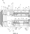
- FIG. 4 is a schematic cross-sectional view of a bearing structure according to a modified example.
- FIG. 1 is a schematic cross-sectional view of the turbocharger TC.
- the direction of arrow L in Figure 1 will be described as the left side of the turbocharger TC.
- the direction of arrow R in Figure 1 will be described as the right side of the turbocharger TC.
- the turbocharger TC has a turbocharger body 1.
- the turbocharger body 1 includes a bearing housing 3, a turbine housing 5, and a compressor housing 7.
- the turbine housing 5 is connected to the left side of the bearing housing 3 by a fastening mechanism 9.
- the compressor housing 7 is connected to the right side of the bearing housing 3 by a fastening bolt 11.
- a protrusion 3a is provided on the outer peripheral surface of the bearing housing 3.
- the protrusion 3a is provided on the turbine housing 5 side.
- the protrusion 3a protrudes in the radial direction of the bearing housing 3.
- a protrusion 5a is provided on the outer peripheral surface of the turbine housing 5.
- the protrusion 5a is provided on the bearing housing 3 side.
- the protrusion 5a protrudes in the radial direction of the turbine housing 5.
- the bearing housing 3 and the turbine housing 5 are band-fastened by a fastening mechanism 9.
- the fastening mechanism 9 is, for example, a G-coupling.
- the fastening mechanism 9 clamps the protrusions 3a and 5a.
- a bearing hole 3b is formed in the bearing housing 3.
- the bearing hole 3b penetrates the bearing housing 3 in the left-right direction.
- a pair of bearings 13 are accommodated in the bearing hole 3b.
- the bearings 13 are rolling bearings.
- the bearings 13 rotatably support the shaft 15.
- a turbine wheel 17 is provided at the left end of the shaft 15.
- the turbine wheel 17 is rotatably housed in the turbine housing 5.
- a compressor wheel 19 is provided at the right end of the shaft 15.
- the compressor wheel 19 is rotatably housed in the compressor housing 7.
- An oil drain port 3c is formed at the bottom of the bearing housing 3 to discharge lubricating oil scattered from the bearings 13.
- the compressor housing 7 is formed with an intake port 21.
- the intake port 21 opens to the right side of the turbocharger TC.
- the intake port 21 is connected to an air cleaner (not shown).
- a diffuser passage 23 is formed by the opposing surfaces of the bearing housing 3 and the compressor housing 7. The diffuser passage 23 pressurizes the air.
- the diffuser passage 23 is formed in an annular shape. The diffuser passage 23 is connected to the intake port 21 on the radially inner side via the compressor impeller 19.
- the compressor housing 7 is provided with a compressor scroll passage 25.
- the compressor scroll passage 25 is formed in an annular shape.
- the compressor scroll passage 25 is located, for example, radially outward of the shaft 15 than the diffuser passage 23.
- the compressor scroll passage 25 is connected to an intake port of an engine (not shown) and the diffuser passage 23.
- the turbine housing 5 is formed with a discharge port 27.
- the discharge port 27 opens to the left side of the turbocharger TC.
- the discharge port 27 is connected to an exhaust gas purification device (not shown).
- the turbine housing 5 is formed with a communication passage 29 and a turbine scroll passage 31.
- the turbine scroll passage 31 is formed in an annular shape.
- the turbine scroll passage 31 is located, for example, radially outside the turbine wheel 17 from the communication passage 29.
- the turbine scroll passage 31 communicates with a gas inlet (not shown). Exhaust gas discharged from an exhaust manifold of an engine (not shown) is introduced to the gas inlet.
- the communication passage 29 connects the turbine scroll passage 31 to the discharge port 27 via the turbine wheel 17.
- the exhaust gas introduced from the gas inlet to the turbine scroll passage 31 is introduced to the discharge port 27 via the communication passage 29 and the turbine wheel 17.
- the exhaust gas introduced to the discharge port 27 rotates the turbine wheel 17 during the flow process.
- the rotational force of the turbine wheel 17 is transmitted to the compressor wheel 19 via the shaft 15.
- the compressor wheel 19 rotates, the air is pressurized as described above. In this way, the air is guided to the engine intake port.
- FIG. 2 is a diagram of the portion enclosed by the dashed dotted line in FIG. 1.
- a bearing structure S is provided inside the bearing housing 3.
- the bearing structure S includes the bearing housing 3, a bearing 13, and a shaft 15.
- the axial direction, circumferential direction, and radial direction of the shaft 15 will also be simply referred to as the axial direction, circumferential direction, and radial direction, respectively.
- bearing 13a and bearing 13b are provided in bearing hole 3b of bearing housing 3.
- Bearing 13a and bearing 13b are spaced apart in the axial direction.
- Bearing 13a is positioned to the left of bearing 13b.
- Bearing 13a is the bearing 13 on the turbine wheel 17 side.
- Bearing 13b is the bearing 13 on the compressor impeller 19 side. As described below, lubricating oil is supplied to bearing 13.
- the bearing 13a includes an inner ring 13a1, an outer ring 13a2, rolling elements 13a3, and a retainer 13a4.
- the inner peripheral surface of the inner ring 13a1 is fitted to the outer peripheral surface of the shaft 15.
- the inner ring 13a1 rotates integrally with the shaft 15.
- the outer ring 13a2 is arranged coaxially with the inner ring 13a1.
- the outer ring 13a2 is provided radially outward from the inner ring 13a1.
- a plurality of rolling elements 13a3 are provided between the inner ring 13a1 and the outer ring 13a2.
- the retainer 13a4 holds the plurality of rolling elements 13a3.
- the bearing 13b includes an inner ring 13b1, an outer ring 13b2, rolling elements 13b3, and a retainer 13b4.
- the inner peripheral surface of the inner ring 13b1 is fitted to the outer peripheral surface of the shaft 15.
- the inner ring 13b1 rotates integrally with the shaft 15.
- the outer ring 13b2 is arranged coaxially with the inner ring 13b1.
- the outer ring 13b2 is provided radially outward from the inner ring 13b1.
- a plurality of rolling elements 13b3 are provided between the inner ring 13b1 and the outer ring 13b2.
- the retainer 13b4 holds the plurality of rolling elements 13b3.
- the rolling elements 13a3 and 13b3 are spherical in shape.
- the rolling elements 13a3 and 13b3 may have a shape other than a sphere, such as a cylindrical shape or a truncated cone shape.
- the inner ring 13a1 is provided integrally with the spacer member 33a.
- the spacer member 33a has a cylindrical shape.
- the left end of the spacer member 33a is connected to the right end of the inner ring 13a1.
- the shaft 15 is inserted into the spacer member 33a.
- the inner ring 13a1 rotates integrally with the spacer member 33a.
- the inner ring 13b1 is provided integrally with the spacer member 33b.
- the spacer member 33b has a cylindrical shape.
- the right end of the spacer member 33b is connected to the left end of the inner ring 13b1.
- the shaft 15 is inserted into the spacer member 33b.
- the inner ring 13b1 rotates integrally with the spacer member 33b.
- the left end of the spacer member 33b abuts against the right end of the spacer member 33a.
- the outer ring 13a2 and the outer ring 13b2 are integral with the fitting member 35.
- the fitting member 35 has a cylindrical shape.
- the outer ring 13a2 is connected to the left end of the inner circumference of the fitting member 35.
- the outer ring 13b2 is connected to the right end of the inner circumference of the fitting member 35.
- the outer peripheral surface of the fitting member 35 is fitted into the inner peripheral surface of the bearing hole 3b.
- the outer ring 13a2, the outer ring 13b2 and the fitting member 35 are held so as not to rotate relative to the inner peripheral surface of the bearing hole 3b.
- a partition wall 3d is provided in the bearing housing 3.
- the partition wall 3d separates the internal space of the bearing housing 3 from the space in the turbine housing 5 in which the turbine wheel 17 is housed.
- the partition wall 3d is provided with a through hole 3d1.
- the through hole 3d1 penetrates the partition wall 3d in the left-right direction.
- a seal ring 37 is attached to the inner peripheral surface of the through hole 3d1.
- the left end of the shaft 15 is fitted into the inner peripheral surface of the seal ring 37.
- the turbine wheel 17 attached to the left end of the shaft 15 is positioned to the left of the partition wall 3d.
- lubricating oil is discharged from bearing 13a to the turbine wheel 17.
- the leakage of the lubricating oil discharged from bearing 13a to the turbine wheel 17 is suppressed by seal ring 37.
- seal ring 37 it may be difficult to sufficiently suppress the leakage of lubricating oil from bearing 13a to the turbine wheel 17 using seal ring 37 alone.
- the bearing structure S of this embodiment is designed to effectively suppress such leakage of lubricating oil.
- a branch source oil passage 3e is formed in the bearing housing 3.
- the branch source oil passage 3e extends in the axial direction of the shaft 15.
- the branch source oil passage 3e extends roughly parallel to the bearing hole 3b.
- the branch source oil passage 3e is located vertically above the bearing hole 3b.
- the branch source oil passage 3e opens to the right.
- a seal plate 39 is attached to the opening of the branch source oil passage 3e.
- the seal plate 39 is roughly annular.
- the seal plate 39 closes the opening of the branch source oil passage 3e.
- the inner diameter of the seal plate 39 is smaller than the inner diameter of the bearing hole 3b.
- a radially inner portion of the seal plate 39 protrudes radially inward beyond the bearing hole 3b.
- a through hole 3f opens into the branch source oil passage 3e.
- the through hole 3f is formed in the bearing housing 3.
- the through hole 3f extends from the outside of the bearing housing 3 to the branch source oil passage 3e. Oil pumped from an oil pump (not shown) is supplied from the through hole 3f to the branch source oil passage 3e.
- the bearing housing 3 is formed with a through hole 3g and a through hole 3h.
- Each of the through hole 3g and the through hole 3h penetrates the bearing housing 3 from the inner peripheral surface of the branch source oil passage 3e to the inner peripheral surface of the bearing hole 3b.
- Each of the through hole 3g and the through hole 3h connects the branch source oil passage 3e and the bearing hole 3b.
- the through hole 3g and the through hole 3h are spaced apart in the axial direction.
- Through holes 35a and 35b are formed in the fitting member 35.
- Each of the through holes 35a and 35b penetrates the fitting member 35 from the outer peripheral surface of the fitting member 35 to the inner peripheral surface of the fitting member 35.
- Each of the through holes 35a and 35b communicates between the outer peripheral surface of the fitting member 35 and the inner peripheral surface of the fitting member 35.
- the through holes 35a and 35b are spaced apart in the axial direction.
- the through hole 3g of the bearing housing 3 and the through hole 35a of the fitting member 35 are in communication with each other. Therefore, lubricating oil is supplied from the branch source oil passage 3e through the through hole 3g and through hole 35a to the inside of the fitting member 35.
- the through hole 3h of the bearing housing 3 and the through hole 35b of the fitting member 35 are in communication with each other. Therefore, lubricating oil is supplied from the branch source oil passage 3e through the through hole 3h and through hole 35b to the inside of the fitting member 35.
- the solid arrows show how lubricating oil is supplied from branch source oil passage 3e through through hole 3g and through hole 35a to the inside of fitting member 35.
- the lubricating oil supplied to the inside of fitting member 35 passes between inner ring 13a1 and outer ring 13a2 of bearing 13a and is discharged to the turbine impeller 17 side.
- the lubricating oil supplied to the inside of fitting member 35 passes between inner ring 13b1 and outer ring 13b2 of bearing 13b and is also discharged to the compressor impeller 19 side.
- the lubricating oil supplied from the branch source oil passage 3e to the bearing hole 3b is also sent to the outer peripheral surface of the fitting member 35.
- the dashed arrow shows how the lubricating oil is supplied from the branch source oil passage 3e through the through hole 3g to the outer peripheral surface of the fitting member 35.
- the lubricating oil supplied to the outer peripheral surface of the fitting member 35 is sent to the left along the axial direction and discharged to the turbine impeller 17 side.
- the lubricating oil supplied to the outer peripheral surface of the fitting member 35 is sent to the right along the axial direction and also discharged to the compressor impeller 19 side.
- An oil thrower 41 is provided radially inward from the seal plate 39.
- the oil thrower 41 is annular.
- the oil thrower 41 is fitted to the outer peripheral surface of the shaft 15.
- the left end of the oil thrower 41 abuts against the right end of the inner ring 13b1 of the bearing 13b.
- the oil thrower 41 scatters the lubricating oil radially outward after lubricating the bearing 13b on the compressor impeller 19 side. This prevents the lubricating oil from leaking from the bearing 13b to the compressor impeller 19.
- a through hole 35c is formed in the lower part of the fitting member 35.
- the axial position of the through hole 35c is between the bearing 13a and the bearing 13b.
- the through hole 35c penetrates the fitting member 35 from the outer peripheral surface of the fitting member 35 to the inner peripheral surface of the fitting member 35.
- the through hole 35c communicates between the outer peripheral surface of the fitting member 35 and the inner peripheral surface of the fitting member 35.
- a through hole 3i is formed in the bearing housing 3 at a position radially opposite the through hole 35c of the fitting member 35.
- the through hole 3i penetrates the bearing housing 3 in the radial direction.
- the through hole 3i connects the bearing hole 3b and the oil drain port 3c (see Figure 1).
- the through hole 35c of the fitting member 35 and the through hole 3i of the bearing housing 3 are connected to each other. Therefore, some of the lubricating oil supplied from the branch source oil passage 3e to the inside of the fitting member 35 is discharged downward through the through hole 35c and the through hole 3i. Some of the lubricating oil supplied from the branch source oil passage 3e to the outer peripheral surface of the fitting member 35 is discharged downward through the through hole 3i.
- FIG. 3 is a cross-sectional view showing the A-A cross section of FIG. 2.
- a side wall portion 3j is formed on the bearing housing 3.
- the side wall portion 3j protrudes radially inward from the inner peripheral surface of the bearing hole 3b.
- the side wall portion 3j is provided to the left of the bearing 13a on the turbine wheel 17 side.
- the side wall portion 3j faces the left side surface of the bearing 13a on the turbine wheel 17 side in the axial direction.
- the side wall portion 3j is annular.
- the side wall portion 3j covers the outer peripheral surface of the shaft 15 over the entire circumferential direction.
- An annular groove 43 is defined between the side wall portion 3j and the bearing 13a.
- the annular groove 43 is a space having a width in the axial direction of the shaft 15 between the right surface of the side wall portion 3j and the left side of the bearing 13a.
- the annular groove 43 extends in the circumferential direction.
- the annular groove 43 is disposed coaxially with the shaft 15.
- Abutment surface 3j1 is provided on the right side surface of side wall portion 3j, radially outward of annular groove 43. Abutment surface 3j1 axially abuts against the left side surface of outer ring 13a2 of bearing 13a and the left side surface 35d of fitting member 35. Annular groove 43 is continuous with the inner peripheral edge of abutment surface 3j1. Annular groove 43 is defined between the right side surface of side wall portion 3j, excluding abutment surface 3j1, and the left side portion of bearing 13a.
- the inner diameter of the annular groove 43 corresponds to the inner diameter of the outer ring 13a2.
- Corresponding to the inner diameter of the outer ring 13a2 does not only mean that it exactly matches the inner diameter of the outer ring 13a2, but can also mean that it is an inner diameter that is shifted from the inner diameter of the outer ring 13a2 by a value within a specified range. However, the inner diameter of the annular groove 43 does not have to correspond to the inner diameter of the outer ring 13a2.
- a communication passage 45 is formed in the bearing housing 3.
- the communication passage 45 is connected to the annular groove 43 and passes through the bearing housing 3 in a direction intersecting the axial direction of the shaft 15.
- the communication passage 45 extends downward from the annular groove 43 and passes through the bearing housing 3 in the radial direction of the shaft 15.
- the extension direction of the communication passage 45 may be inclined relative to the radial direction when viewed in a direction perpendicular to the axial direction, and may be inclined relative to the vertical direction when viewed in the axial direction.
- the communication passage 45 communicates between the annular groove 43 and the oil drain port 3c (see Figure 1).
- the side wall portion 3j faces the rolling element 13a3 in the axial direction of the shaft 15 over the entire circumferential area of the shaft 15.
- the lubricating oil discharged to the turbine wheel 17 side after passing between the inner ring 13a1 and the outer ring 13a2 of the bearing 13a on the turbine wheel 17 side collides with the side wall portion 3j. Therefore, the lubricating oil discharged to the turbine wheel 17 side from the bearing 13a is prevented from leaking to the turbine wheel 17 side beyond the side wall portion 3j.
- the lubricating oil discharged to the turbine wheel 17 side from the bearing 13a passes through the annular groove 43 and the communication passage 45 in that order and is discharged downward.
- the side wall portion 3j faces the outer peripheral edge of the side surface 35d of the fitting member 35 in the axial direction of the shaft 15 over the entire circumferential area of the shaft 15.
- the lubricating oil that passes through the outer peripheral surface of the fitting member 35 and is discharged to the turbine wheel 17 side collides with the side wall portion 3j. Therefore, the lubricating oil discharged from the outer peripheral surface of the fitting member 35 to the turbine wheel 17 side is prevented from leaking beyond the side wall portion 3j to the turbine wheel 17 side. Then, after colliding with the side wall portion 3j, the lubricating oil discharged from the outer peripheral surface of the fitting member 35 to the turbine wheel 17 side is discharged downward through the communication passage 45.
- the shaft 15 is provided with an expanded diameter section 15a, the outer diameter of which is expanded relative to the surrounding area, to the left of the bearing 13a on the turbine impeller 17 side.
- the right end of the expanded diameter section 15a abuts against the left end of the inner ring 13a1 of the bearing 13a.
- a portion of the inner circumferential surface of the side wall section 3j and a portion of the outer circumferential surface of the expanded diameter section 15a face each other in the radial direction.
- the narrowed portion 47a is formed by the side wall portion 3j and the enlarged diameter portion 15a.
- the narrowed portion 47a is a portion where the gap between the inner peripheral surface of the bearing housing 3 and the outer peripheral surface of the shaft 15 is narrower than the surroundings.
- the shaft 15 is provided with an enlarged diameter portion 15b, which is different from the enlarged diameter portion 15a, to the left of the enlarged diameter portion 15a.
- the enlarged diameter portion 15b is a portion of the shaft 15 whose outer diameter is enlarged relative to the surroundings, like the enlarged diameter portion 15a.
- the inner peripheral surface of the bearing housing 3 and the enlarged diameter portion 15b form a narrowed portion 47b, which is different from the narrowed portion 47a.
- a plurality of narrowed portions 47a, 47b are provided at intervals in the axial direction of the shaft 15 between the bearing 13a on the turbine wheel 17 side and the seal ring 37. This more effectively prevents the lubricating oil discharged from the outer peripheral surface of the bearing 13a or the fitting member 35 to the turbine wheel 17 side from leaking to the turbine wheel 17 side from the side wall portion 3j.
- the bearing structure S includes a side wall portion 3j that faces the rolling element 13a3 in the axial direction of the shaft 15 over the entire circumferential area of the shaft 15, an annular groove 43 that is defined between the side wall portion 3j and the bearing 13a and extends in the circumferential direction, and a communication passage 45 that connects the annular groove 43 to the oil drain port 3c and penetrates the bearing housing 3 in a direction intersecting the axial direction.
- the lubricating oil that passes between the inner ring 13a1 and the outer ring 13a2 of the bearing 13a and is discharged to the turbine wheel 17 side can be made to collide with the side wall portion 3j, discharged downward through the annular groove 43 and the communication passage 45, and discharged to the outside from the oil drain port 3c. Therefore, leakage of the lubricating oil to the turbine wheel 17 side can be suppressed.
- the bearing structure S according to this embodiment can improve oil sealing performance. Furthermore, the retention of lubricating oil around the bearing 13a is suppressed, which also suppresses mechanical losses caused by the retention of lubricating oil.
- the side wall portion 3j is provided integrally with the bearing housing 3.
- the side wall portion 3j may be provided as a separate material from the bearing housing 3 and attached to the bearing housing 3.
- the side wall portion 3j faces the outer peripheral edge of the side surface 35d of the fitting member 35 in the axial direction of the shaft 15 over the entire circumferential area of the shaft 15. This allows the lubricating oil that passes through the outer peripheral surface of the fitting member 35 and is discharged to the turbine wheel 17 side to collide with the side wall portion 3j, be discharged downward through the communication passage 45, and be discharged to the outside through the oil drain port 3c. This makes it possible to more effectively prevent the lubricating oil from leaking to the turbine wheel 17 side. This makes it possible to more effectively improve the oil sealing performance.
- the side wall portion 3j does not have to face the outer peripheral edge of the side surface 35d of the fitting member 35 in the axial direction of the shaft 15 in a portion of the circumferential direction of the shaft 15.
- the fitting member 35 is provided integrally with the outer ring 13a2.
- the fitting member 35 may be provided separately from the outer ring 13a2.
- the fitting member 35 is also provided separately from the outer ring 13b2.
- the outer peripheral surface of the outer ring 13a2 and the outer peripheral surface of the outer ring 13b2 are fitted into the inner peripheral surface of the fitting member 35.
- the inner ring 13a1 is provided integrally with the spacer member 33a. However, the inner ring 13a1 may be provided separately from the spacer member 33a. In the example of Figs. 2 and 3, the inner ring 13b1 is provided integrally with the spacer member 33b. However, the inner ring 13b1 may be provided separately from the spacer member 33b.
- FIG. 4 is a schematic cross-sectional view of a modified bearing structure SA.
- the modified bearing structure SA differs from the modified bearing structure S described above in that a guide portion 49 is provided in the communication passage 45.
- the guide portion 49 has a guide surface 49a facing the communication passage 45.
- the guide surface 49a extends in a direction perpendicular to the left-right and up-down directions, and also extends in a lower right direction toward the oil drain port 3c.
- the lubricating oil discharged from the outer peripheral surface of the bearing 13a or the fitting member 35 toward the turbine wheel 17 is sent to the communication passage 45 after colliding with the side wall portion 3j, and is guided by the guide surface 49a of the guide portion 49 in the direction toward the oil drain port 3c. This allows the lubricating oil discharged through the communication passage 45 to be scattered toward the oil drain port 3c, thereby more effectively suppressing leakage of the lubricating oil toward the turbine wheel 17.
- the side wall portion 3j, the annular groove 43, and the communication passage 45 are provided for the bearing 13a on the turbine wheel 17 side of the turbocharger TC.
- the side wall portion 3j, the annular groove 43, and the communication passage 45 may also be provided for the bearings 13 other than the bearing 13a of the turbocharger TC. This makes it possible to suppress leakage of lubricating oil to parts other than the turbine wheel 17 that are arranged around the bearing 13.
- the bearing structures S and SA are provided in the turbocharger TC.
- the bearing structures S and SA may also be applied to devices other than the turbocharger TC that have rolling bearings.
Landscapes
- Engineering & Computer Science (AREA)
- General Engineering & Computer Science (AREA)
- Mechanical Engineering (AREA)
- Chemical & Material Sciences (AREA)
- Combustion & Propulsion (AREA)
- Supercharger (AREA)
- Rolling Contact Bearings (AREA)
Priority Applications (4)
| Application Number | Priority Date | Filing Date | Title |
|---|---|---|---|
| DE112023005487.8T DE112023005487T5 (de) | 2023-04-14 | 2023-11-13 | Lagerstruktur und Turbolader |
| CN202380092456.2A CN120604024A (zh) | 2023-04-14 | 2023-11-13 | 轴承构造及增压器 |
| JP2025513786A JPWO2024214326A1 (https=) | 2023-04-14 | 2023-11-13 | |
| US19/273,280 US20250341218A1 (en) | 2023-04-14 | 2025-07-18 | Bearing structure and turbocharger |
Applications Claiming Priority (2)
| Application Number | Priority Date | Filing Date | Title |
|---|---|---|---|
| JP2023066482 | 2023-04-14 | ||
| JP2023-066482 | 2023-04-14 |
Related Child Applications (1)
| Application Number | Title | Priority Date | Filing Date |
|---|---|---|---|
| US19/273,280 Continuation US20250341218A1 (en) | 2023-04-14 | 2025-07-18 | Bearing structure and turbocharger |
Publications (1)
| Publication Number | Publication Date |
|---|---|
| WO2024214326A1 true WO2024214326A1 (ja) | 2024-10-17 |
Family
ID=93058870
Family Applications (1)
| Application Number | Title | Priority Date | Filing Date |
|---|---|---|---|
| PCT/JP2023/040771 Ceased WO2024214326A1 (ja) | 2023-04-14 | 2023-11-13 | 軸受構造および過給機 |
Country Status (5)
| Country | Link |
|---|---|
| US (1) | US20250341218A1 (https=) |
| JP (1) | JPWO2024214326A1 (https=) |
| CN (1) | CN120604024A (https=) |
| DE (1) | DE112023005487T5 (https=) |
| WO (1) | WO2024214326A1 (https=) |
Citations (5)
| Publication number | Priority date | Publication date | Assignee | Title |
|---|---|---|---|---|
| JPS6078942U (ja) * | 1983-11-07 | 1985-06-01 | 石川島播磨重工業株式会社 | 過給機の軸受車室 |
| JP2011111900A (ja) * | 2009-11-24 | 2011-06-09 | Toyota Motor Corp | 過給機のタービン軸支持構造 |
| JP2014125921A (ja) * | 2012-12-26 | 2014-07-07 | Nsk Ltd | ターボチャージャ用玉軸受ユニット |
| JP6168739B2 (ja) * | 2012-07-18 | 2017-07-26 | 株式会社ジェイテクト | ターボチャージャ用軸受装置 |
| JP2020007931A (ja) * | 2018-07-05 | 2020-01-16 | 株式会社豊田自動織機 | 電動式過給機 |
Family Cites Families (3)
| Publication number | Priority date | Publication date | Assignee | Title |
|---|---|---|---|---|
| DE3531313C3 (de) * | 1984-09-03 | 1995-04-20 | Ishikawajima Harima Heavy Ind | Lagervorrichtung in einem Turbolader |
| JP6253024B2 (ja) * | 2014-10-24 | 2017-12-27 | 三菱重工業株式会社 | ターボチャージャ |
| US9638203B2 (en) * | 2015-09-15 | 2017-05-02 | Borgwarner Inc. | Bearing housing |
-
2023
- 2023-11-13 WO PCT/JP2023/040771 patent/WO2024214326A1/ja not_active Ceased
- 2023-11-13 CN CN202380092456.2A patent/CN120604024A/zh active Pending
- 2023-11-13 DE DE112023005487.8T patent/DE112023005487T5/de active Pending
- 2023-11-13 JP JP2025513786A patent/JPWO2024214326A1/ja active Pending
-
2025
- 2025-07-18 US US19/273,280 patent/US20250341218A1/en active Pending
Patent Citations (5)
| Publication number | Priority date | Publication date | Assignee | Title |
|---|---|---|---|---|
| JPS6078942U (ja) * | 1983-11-07 | 1985-06-01 | 石川島播磨重工業株式会社 | 過給機の軸受車室 |
| JP2011111900A (ja) * | 2009-11-24 | 2011-06-09 | Toyota Motor Corp | 過給機のタービン軸支持構造 |
| JP6168739B2 (ja) * | 2012-07-18 | 2017-07-26 | 株式会社ジェイテクト | ターボチャージャ用軸受装置 |
| JP2014125921A (ja) * | 2012-12-26 | 2014-07-07 | Nsk Ltd | ターボチャージャ用玉軸受ユニット |
| JP2020007931A (ja) * | 2018-07-05 | 2020-01-16 | 株式会社豊田自動織機 | 電動式過給機 |
Also Published As
| Publication number | Publication date |
|---|---|
| US20250341218A1 (en) | 2025-11-06 |
| CN120604024A (zh) | 2025-09-05 |
| DE112023005487T5 (de) | 2025-11-27 |
| JPWO2024214326A1 (https=) | 2024-10-17 |
Similar Documents
| Publication | Publication Date | Title |
|---|---|---|
| KR101454997B1 (ko) | 원심 압축 장치 및 그 조립 방법 | |
| JP5569113B2 (ja) | ターボチャージャ | |
| US11441602B2 (en) | Bearing structure and turbocharger | |
| JP6601499B2 (ja) | 軸受構造、および、過給機 | |
| JPWO2017026270A1 (ja) | 軸受構造、および、過給機 | |
| US10443439B2 (en) | Bearing structure and turbocharger | |
| JP7501646B2 (ja) | オイルディフレクタおよび過給機 | |
| WO2024214326A1 (ja) | 軸受構造および過給機 | |
| WO2018092781A1 (ja) | 軸受構造および過給機 | |
| US20190107052A1 (en) | Turbocharger | |
| JP7164346B2 (ja) | 回転機械及び過給機 | |
| US11846295B2 (en) | Turbocharger | |
| CN114364867B (zh) | 多圆弧轴承以及增压器 | |
| JP2014051897A (ja) | 過給機 | |
| JP2019218912A (ja) | ターボチャージャ | |
| CN110785549B (zh) | 增压器 | |
| JP2012112359A (ja) | 軸流排気タービンの軸受台カバーおよび軸流排気タービン | |
| JP7468696B2 (ja) | 軸受および過給機 | |
| CN114981548A (zh) | 轴承以及增压器 | |
| WO2025032930A1 (ja) | オイルディフレクタおよび過給機 | |
| WO2017014084A1 (ja) | 軸受構造および過給機 | |
| JP2025173292A (ja) | サイレンサ及び過給機 | |
| WO2024161750A1 (ja) | 過給機 | |
| WO2022118606A1 (ja) | 軸受構造、および、過給機 | |
| JP2020051393A (ja) | 排気ターボ過給機の軸受の構造 |
Legal Events
| Date | Code | Title | Description |
|---|---|---|---|
| 121 | Ep: the epo has been informed by wipo that ep was designated in this application |
Ref document number: 23933100 Country of ref document: EP Kind code of ref document: A1 |
|
| ENP | Entry into the national phase |
Ref document number: 2025513786 Country of ref document: JP Kind code of ref document: A |
|
| WWE | Wipo information: entry into national phase |
Ref document number: 2025513786 Country of ref document: JP |
|
| WWE | Wipo information: entry into national phase |
Ref document number: 202380092456.2 Country of ref document: CN |
|
| WWE | Wipo information: entry into national phase |
Ref document number: 112023005487 Country of ref document: DE |
|
| WWP | Wipo information: published in national office |
Ref document number: 202380092456.2 Country of ref document: CN |
|
| WWP | Wipo information: published in national office |
Ref document number: 112023005487 Country of ref document: DE |
|
| 122 | Ep: pct application non-entry in european phase |
Ref document number: 23933100 Country of ref document: EP Kind code of ref document: A1 |