WO2024214293A1 - 製造方法 - Google Patents
製造方法 Download PDFInfo
- Publication number
- WO2024214293A1 WO2024214293A1 PCT/JP2023/015203 JP2023015203W WO2024214293A1 WO 2024214293 A1 WO2024214293 A1 WO 2024214293A1 JP 2023015203 W JP2023015203 W JP 2023015203W WO 2024214293 A1 WO2024214293 A1 WO 2024214293A1
- Authority
- WO
- WIPO (PCT)
- Prior art keywords
- battery unit
- electrode tabs
- tip portions
- overlapped
- main body
- Prior art date
- Legal status (The legal status is an assumption and is not a legal conclusion. Google has not performed a legal analysis and makes no representation as to the accuracy of the status listed.)
- Ceased
Links
Images



Classifications
-
- Y—GENERAL TAGGING OF NEW TECHNOLOGICAL DEVELOPMENTS; GENERAL TAGGING OF CROSS-SECTIONAL TECHNOLOGIES SPANNING OVER SEVERAL SECTIONS OF THE IPC; TECHNICAL SUBJECTS COVERED BY FORMER USPC CROSS-REFERENCE ART COLLECTIONS [XRACs] AND DIGESTS
- Y02—TECHNOLOGIES OR APPLICATIONS FOR MITIGATION OR ADAPTATION AGAINST CLIMATE CHANGE
- Y02E—REDUCTION OF GREENHOUSE GAS [GHG] EMISSIONS, RELATED TO ENERGY GENERATION, TRANSMISSION OR DISTRIBUTION
- Y02E60/00—Enabling technologies; Technologies with a potential or indirect contribution to GHG emissions mitigation
- Y02E60/10—Energy storage using batteries
Definitions
- the present invention relates to manufacturing technology for battery modules.
- Patent Documents 1 to 4 One example of such a technology has been proposed in which the positive and negative electrode tabs extending from the battery units are joined between the battery units, and these tabs are then further bent to manufacture a battery module in which multiple battery units are integrated in a stacked configuration.
- Patent No. 6789858 JP 2006-185733 A Patent No. 4568646 JP 2022-109732 A
- Each battery unit may have multiple positive electrode tabs and multiple negative electrode tabs.
- the joining work can be made easier by stacking the multiple positive electrode tabs together and stacking the multiple negative electrode tabs together, and then joining the combined multiple positive electrode tabs and the combined multiple negative electrode tabs.
- bending after the joining work may cause the tabs to bend or warp, and unintended stress caused by this bending or warping may act on the battery unit body.
- the object of the present invention is to prevent bending or distortion of the tabs when multiple tabs are joined together and bent.
- a manufacturing method for a battery module in which a plurality of battery units are electrically connected in series and arranged in a thickness direction to be integrated comprising the steps of:
- Each battery unit is A main body portion including an electricity storage element and having a thickness in the thickness direction; a plurality of plate-shaped positive electrode tabs spaced apart in the thickness direction and extending from the main body in a direction intersecting the thickness direction; a plurality of plate-shaped negative electrode tabs spaced apart in the thickness direction and extending from the main body in a direction intersecting the thickness direction,
- the plurality of positive electrode tabs include two outer positive electrode tabs located on both sides in the thickness direction,
- the plurality of negative electrode tabs include two outer negative electrode tabs located on both sides in the thickness direction,
- the manufacturing method includes: a first stacking step of stacking first tip portions of the plurality of positive electrode tabs of a first battery unit in the thickness direction; a second stacking step of stacking, in the thickness direction, second tip portions of the plurality of negative electrode tab
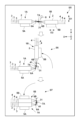
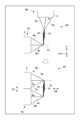
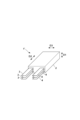
- 1A and 1B are diagrams showing examples of a battery unit and a battery module.
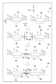
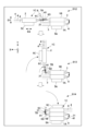
- 1A to 1C are diagrams showing a manufacturing method according to an embodiment of the present invention.
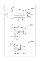
- 1A to 1C are diagrams showing a manufacturing method according to an embodiment of the present invention.
- FIG. 13 is a diagram showing an ideal shape of a tab after bending.
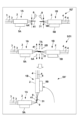
- 1A to 1C are diagrams showing a manufacturing method according to an embodiment of the present invention.
- 1A to 1C are diagrams showing a manufacturing method according to an embodiment of the present invention.
- 1A to 1C are diagrams showing a manufacturing method according to an embodiment of the present invention.
- 1A to 1C are diagrams showing a manufacturing method according to an embodiment of the present invention.
- 11A to 11C are diagrams showing a modified example of a manufacturing method according to an embodiment of the present invention.
- FIG. 13 is a diagram showing
- First Embodiment ⁇ Battery unit and battery module> 1 is a diagram showing a battery unit 1 and a battery module 10 to which the present invention can be applied.
- the battery unit 1 has a main body 2 and a plurality of electrode tabs (lead tabs) 3 and 4 extending from the main body 2.
- One of the electrode tab 3 and the electrode tab 4 is a positive electrode tab, and the other is a negative electrode tab.
- the electrode tab 3 is a negative electrode tab
- the electrode tab 4 is a positive electrode tab.
- the main body 2 has an exterior body and a storage element sealed inside it.
- the storage element includes, for example, a laminate of a positive electrode layer, a negative electrode layer, and a solid electrolyte layer. Electricity can be supplied from the outside to the storage element via the electrode tabs 3 or 4, and the storage element can be charged. In addition, electricity can be discharged from the storage element to the outside via the electrode tabs 3 or 4.
- the main body 2 has a rectangular parallelepiped shape, with arrow D1 indicating its thickness direction, arrow D2 indicating its longitudinal direction, and arrow D3 indicating its width direction.
- the directions D1, D2, and D3 intersect with each other, and in this embodiment, are perpendicular to each other.
- the electrode tab 3 is a plate-shaped conductive member (e.g., a metal plate) that extends outward in the D2 direction from one end face of the main body 2 in the D2 direction
- the electrode tab 4 is a plate-shaped conductive member (e.g., a metal plate) that extends outward in the D2 direction from the other end face of the main body 2 in the D2 direction.
- the extension directions (protrusion directions) of the electrode tabs 3 and 4 are both in the D2 direction, but in opposite directions.
- Both electrode tabs 3 and 4 extend a predetermined length in the D2 direction and are band-shaped (rectangle) with a predetermined thickness in the D1 direction and a predetermined width in the D3 direction.
- three electrode tabs 3 are provided, and are arranged at equal pitches in the D1 direction.
- Three electrode tabs 4 are also provided, and are arranged at equal pitches in the D1 direction.
- the battery module 10 is formed by electrically connecting multiple battery units 1 in series. That is, the electrode tab 3 of one battery unit 1 is connected to the electrode tab 4 of another battery unit 1.
- the battery module 10 also integrates multiple battery units 1 arranged in the D1 direction.
- the battery module 10 in the example of Figure 1 is formed by stacking multiple battery units 1 in the D1 direction so that the positions of the electrode tabs 3 and electrode tabs 4 of adjacent battery units 1 in the D1 direction are alternately inverted.
- the tip portions 31 of the three electrode tabs 3 are overlapped for each battery unit 1, and the tip portions 41 of the three electrode tabs 4 are overlapped.
- the tip portions 31 and 41 are joined between adjacent battery units 1.
- the three electrode tabs 3 are bent approximately 90 degrees, and the three electrode tabs 4 are also bent approximately 90 degrees.
- the root portions of the electrode tabs 3 are fixed to the main body 2, and their positions are invariable relative to the main body 2.
- the root portions of the electrode tabs 4 are similarly fixed to the main body 2, and their positions are invariable relative to the main body 2.
- the tip portions 31 and 41 refer to sections of a predetermined length from the tips of the electrode tabs 3 and 4 in the D2 direction.
- the electrode tab 3 of one battery unit 1 located at the end of the battery module 10 in the D1 direction and the electrode tab 4 of the other battery unit 1 are open and are connected to an electrical load or a charger.
- one battery module 10 is formed from seven battery units 1.
- the number of battery units 1 forming the battery module 10 is not limited to this, and for example, one battery module 10 can be formed from two battery units 1, or one battery module 10 can be formed from eight or more battery units 1.
- ⁇ Production Method> An example of a manufacturing method for the battery module 10 will be described.
- two battery units 1 are connected in series and arranged side by side in the D1 direction, and then the third and subsequent battery units 1 are sequentially connected to the formed parts of the battery module 10 and arranged side by side in the D1 direction.
- the battery module 10 is manufactured by this manufacturing procedure.
- FIGS. 1 and 3 are schematic diagrams showing an example of a manufacturing method.
- arrows X and Y indicate horizontal directions perpendicular to each other, and the Z direction indicates the up-down direction.
- 2 and 3 show the manufacturing process in a plan view, in which the battery units 1 are stacked side by side in the Y direction.
- the manufacturing method can be performed by a dedicated automatic manufacturing device or by manual work.
- Step S1 in FIG. 2 is a preparation step.
- the two battery units 1 (1A, 1B) to be connected are first arranged.
- Battery unit 1A is held by holding unit 5A
- battery unit 1B is held by holding unit 5B.
- Holding units 5A and 5B hold battery unit 1, for example, by suction.
- Battery units 1A and 1B are held in a position in which their D1 direction is the Y direction and their D2 direction is the X direction, and each main body 2 faces in the D2 direction, and the electrode tab 4 of battery unit 1A and the electrode tab 3 of battery unit 1B, which are electrically connected in series, face each other.
- battery units 1A and 1B are arranged slightly offset from each other in the Y direction, but they may be arranged in the same position in the Y direction.
- Step S2 in FIG. 2 is a stacking step.
- the tip portions 41 of the multiple electrode tabs 4 of the battery unit 1A are stacked in the D1 direction (Y direction).
- the three electrode tabs 4 are pressed in the Y direction by the clamping tool 6A and clamped to stack the tip portions 41 of the electrode tabs 4.
- the tip portions 31 of the multiple electrode tabs 3 of the battery unit 1B are also stacked in the D1 direction (Y direction).
- the three electrode tabs 3 are pressed in the Y direction by the clamping tool 6B and clamped to stack the tip portions 31 of the electrode tabs 3.
- Step S3 in FIG. 2 is a positioning step.
- the holding unit 5B is moved in the X direction to move the battery unit 1B closer to the battery unit 1A, and the tip portions 41 and 31 overlapped in step S2 are overlapped in the Y direction.
- only the holding unit 5B is moved in the X direction in step S3, but it may also be moved in the Y direction, or only the holding unit 5A or both the holding units 5A and 5B may be moved.
- Step S4 in FIG. 2 is a joining preparation step.
- each tip 31 and each tip 41 stacked in the Y direction are pressed in the Y direction and clamped by clamping tool 7A. This allows each tip 31 and each tip 41 to be tightly attached in the Y direction.
- Step S5 in FIG. 3 is a joining step.
- the joining step the battery units 1A and 1B are placed face to face, and the tip portions 31 and 41 that were brought into close contact in the joining preparation step are joined.
- the joining is performed by welding using a welding machine 8.
- the tip portions 31 and 41 are fixed to each other and electrically conductive, and the battery units 1A and 1B are connected.
- the joining method may be mechanical joining using fasteners (rivets, bolts and nuts) other than welding.
- Steps S6 and S7 in FIG. 3 are bending steps.
- the joined electrode tabs 3 and 4 are bent so that the main body 2 of the battery unit 1A and the main body 2 of the battery unit 1B are aligned in the D1 direction.
- the bending step in this embodiment is performed in two steps, steps S6 and S7.
- step S6 the holding unit 5B, clamping device 6B, and clamping device 7A rotate 90 degrees counterclockwise together, with the Z-direction axis passing near clamping device 6A as the central axis.
- This causes the battery unit 1B to rotate along with the holding unit 5B.
- the position of the holding unit 5A remains unchanged, and the position of the battery unit 1A is fixed.
- each electrode tab 4 of the battery unit 1A bends between clamping device 6A and clamping device 7A, and each tip 41 that was oriented in the X direction now faces the Y direction.
- the shape of each electrode tab 3 of the battery unit 1A does not change.
- clamping device 6A may move in the X direction or Y direction in accordance with the deformation of each electrode tab 4.
- step S7 the holding unit 5B and the clamping device 6B rotate 90 degrees counterclockwise together, with the Z-axis passing near the clamping device 7A at the end of step S6 as the central axis.
- This causes the battery unit 1B to rotate together with the holding unit 5B.
- the position of the clamping device 7A is fixed.
- the position of the holding unit 5A is unchanged, and the position of the battery unit 1A is fixed.
- the main body 2 of the battery unit 1B overlaps the main body 2 of the battery unit 1A in the Y direction.
- Each electrode tab 3 of the battery unit 1B bends between the clamping device 6B and the clamping device 7A, and each tip 31 remains oriented in the Y direction.
- the clamping device 6B may also move in the X or Y direction in accordance with the deformation of each electrode tab 3.
- the position of the battery unit 1A is fixed and the bending process is performed while displacing the battery unit 1B, but it is also possible to perform the bending process while displacing both.
- battery unit 1A and battery unit 1B are electrically connected in series and arranged side by side in direction D1 (direction Y).
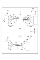
- Fig. 4A illustrates only the main body 2 and three electrode tabs 4 of the battery unit 1A, and does not illustrate the battery unit 1B, the holding units 5A and 5B, and the clamps 6A, 6B, and 7A.
- Embodiment EM0 in Figure 4A shows the state of the three electrode tabs 4 of the battery unit 1A immediately before the stacking step S2.
- the three electrode tabs 4 include two outer electrode tabs 4a, 4b located on both sides in the D1 direction, and a central inner electrode tab 4c.
- the outer electrode tab 4a and the outer electrode tab 4b are separated by a distance W, and the inner electrode tab 4c is located at the center CL between these outer electrode tabs 4a, 4b.
- the three electrode tabs 4 are band-shaped members with a length L that extend from the main body 2 in the D2 direction.
- Example EX1 shows a case where the overlapping step S2 is performed with the overlapping positions of the three electrode tabs 4 set to the center CL in the D1 direction, and the overlap start position OP set to a position d0 away from the main body 2 in the D2 direction.
- the outer electrode tabs 4a and 4b are inclined from the main body 2 toward the overlap start position OP, and are bent from the overlap start position OP to be parallel to the center CL.
- the inner electrode tab 4c is not bent and coincides with the center CL.
- the outer electrode tabs 4a and 4b are bent symmetrically with respect to the inner electrode tab 4c.
- each tip 41 of the three electrode tabs 4a to 4c When referring to each tip 41 of the three electrode tabs 4a to 4c individually, they are written as tip 41a, 41b, and 41c. In the section from the overlap start position OP to each tip of the three electrode tabs 4a to 4c, the tips 41a to 41c are in close contact. In this case, the lengths L1a and L1b in the D2 direction of the tips 41a and 41b of the outer electrode tabs 4a and 4b are the same, and the length L1c in the D2 direction of the tip 41c of the inner electrode tab 4c is longer in the D2 direction than the lengths L1a and L1b. In other words, the tip of the inner electrode tab 4c protrudes in the D2 direction further than the tips of the outer electrode tabs 4a and 4b.
- each tip 41 of the three electrode tabs 4 becomes a joint (joint section) where it is joined to the electrode tab 3 of the battery unit 3. Since the electrode tabs 3 and 4 are fixed at the joint, the length of each electrode tab 4 from the main body 2 to the joint does not change before and after the bending process S6 described above.
- FIG. 4B shows an example EX2' of an ideal shape in the bending process S6.
- the inner electrode tab 4c extends straight along the center CL
- the outer electrode tabs 4a and 4b extend straight to the bent portion (the two-dot chain circle portion) while being inclined with respect to the center CL.
- example EX2' is difficult to form from the shape of example EX1.
- the lengths of electrode tabs 4a and 4b are different at the bent portion, with electrode tab 4b on the outside of the bend being longer than electrode tab 4a on the inside of the bend.
- electrode tab 4b is longer than electrode tab 4a by (R2-R1) ⁇ /2 at the bent portion.
- example EX2' which is an ideal bent shape, cannot be formed from the state of example EX1.
- Example EX2 shows the actual shape of the electrode tab 4 when bending step S6 is performed from the shape of Example EX1.
- the length of the tab from the main body 2 to the joint of electrode tabs 4a and 4b is the same.
- the difference in bending radius results in the length of the tab at the bend being longer for electrode tab 4b than for tab 4a.
- the outer electrode tab 4a which is located on the inside in the bending direction, is longer than the overlap start position OP due to bending, and bends inward in the bending direction.
- the inner electrode tab 4c also bends slightly inward in the bending direction.
- the outer electrode tab 4b which is located on the outside in the bending direction, is longer than the overlap start position OP due to bending, and is in a taut state. Because the roots of the three electrode tabs 4a to 4c are fixed to the main body 2, such distortions can apply stress to the main body 2, causing deterioration of the main body 2.
- the overlapping step S2 is performed at a position offset in the D1 direction from the center CL.
- the overlapping positions of the three electrode tabs 4 are offset in the D1 direction from the center CL by an offset amount d1.
- the overlap start position OP is a position d2 away from the main body 2 in the D2 direction. All three electrode tabs 4a to 4c extend at an angle from the main body 2 toward the overlap start position OP with respect to the center CL, and are bent from the overlap start position OP so as to be parallel to the center CL.
- each tip 41a, 41b, 41c has a length L3a, L3b, L3 from the overlap start position OP to each tip.
- the lengths L3a, L3b, L3c of each tip 41a, 41b, 41b have a relationship of L3c>L3a>L3b. That is, in this embodiment, the tip of electrode tab 4c protrudes the most in the D2 direction, followed by the tip of electrode tab 4a.
- L3a>L3c>L3b may be satisfied, with electrode tab 4a protruding the most, followed by the tip of electrode tab 4c.
- each tip 41 of the three electrode tabs 4 becomes a joining section (joining section) where the electrode tab 3 of the battery unit 3 is joined.
- Embodiment EM2 in Figure 4A shows the shape after performing steps S3 to S5 and bending step S6 after performing overlapping step S2 as in embodiment EM1.
- the direction in which the electrode tab 4 is bent in bending step S6 is the direction in which the overlapping position is offset in overlapping step S2.
- each electrode tab 4a to 4c is bent while generally returning to the center CL side, and it can be seen that the distortion of each electrode tab 4a to 4c is smaller than in example EX2.
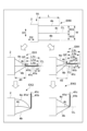
- Figure 5 is a diagram explaining the offset in the D1 direction of the overlapping positions of electrode tab 3 and electrode tab 4 in this embodiment, showing an enlarged view of steps S2 and S3. Also, in Figure 5, the holding units 5A, 5B, and clamping devices 6A, 6B, and 7A are omitted from the illustration.
- the overlapping positions of the electrode tabs 3 and 4 are offset in the same bending direction (Y1 direction).
- the overlapping positions of the tip portions 41 of the battery unit 1A are offset in the Y1 direction from the center CL in the D1 direction by an offset amount d11.
- the overlapping start position OP is a position d21 away from the main body portion 2 of the battery unit 1A in the D2 direction.
- the overlapping positions of the tip portions 31 of the battery unit 1B are offset in the Y1 direction from the center CL in the D1 direction by an offset amount d12.
- the overlapping start position OP is a position d22 away from the main body portion 2 of the battery unit 1B in the D2 direction.
- each tip 41 is located on the inside of the bend, and each tip 31 is located on the outside. In other words, each tip 41 is located on the side of the main body 2 relative to each tip 31.
- the bending position of each electrode tab 4 after bending step S7 is located closer to the main body 2 in the D2 direction than the bending position of each electrode tab 3.
- each electrode tab 4 from the main body 2 to the joint in the joining process S5 is the same as the length of each electrode tab 4 from the main body 2 to the joint after the bending process S7. The same is true for each electrode tab 3.
- the relationship between the lengths of d11, d12, d21, and d22 at the overlapping positions is d11>d12, d21 ⁇ d22. This makes it possible to suppress the generation of internal stress in each of the electrode tabs 3 and 4 after bending.
- the overlapping positions in the D1 and D2 directions are d11>d12 and d21 ⁇ d22, but other dimensional relationships can also be used.
- d11, d12, d21, and d22 can be determined so that the difference in length from the main body 2 to the joint of each of the electrode tabs 3 and 4 in the overlapping step S2 is equal to the difference in length from the main body 2 to the joint of each of the electrode tabs 3 and 4 in the bending steps S6 and S7 in a state where the generation of internal stress can be suppressed.
- FIG. 6 shows an enlarged view of steps S6 and S7.
- FIG. 6 illustrates only the main body 2 and three electrode tabs 4 of the battery unit 1A, and does not illustrate the battery unit 1B, holding units 5A, 5B, and clamps 6A, 6B, and 7A.
- step S6 the electrode tabs 4a to 4c of the battery unit 1A are bent as they return to the center CL of the battery unit 1A.
- the electrode tabs 3a to 3c of the battery unit 1B are not changed from the state in steps S2 and S3 in FIG. 5 (offset from the center CL).
- step S7 in FIG. 6 the electrode tabs 3a to 3c of the battery unit 1B are also bent as they return to the center CL of the battery unit 1B.
- Step S8 in FIG. 7 is a preparation step.
- the two connected battery units 1A and 1B are held in the holding unit 5A, and the third battery unit 1C to be connected next is held in the holding unit 5C.
- the holding unit 5C is the same unit as the holding units 5A and 5B.
- the battery unit 1C is held in a position in which its D1 direction is the Y direction and its D2 direction is the X direction.
- the main body 2 of the battery unit 1C is disposed so as to face the main body 2 of the battery unit 1B in the D2 direction, and the battery unit 1C is held in a position in which the electrode tabs 3 of the battery unit 1C and the electrode tabs 4 of the battery unit 1B, which are electrically connected in series, face each other.
- Step S10 in FIG. 7 is a positioning step, which corresponds to step S3 in FIG. 2.
- the holding unit 5C is moved in the X direction to move the battery unit 1C closer to the battery unit 1B, and the tip portions 31 and 41 overlapped in step S9 are overlapped in the Y direction.
- only the holding unit 5C is moved in the X direction in step S10, but it may also be moved in the Y direction, or only the holding unit 5A or both the holding units 5A and 5C may be moved.
- Step S12 in FIG. 8 is a joining step, which corresponds to step S5 in FIG. 3.
- the joining step the battery units 1C and 1B are placed face to face, and the tip portions 31 and 41 that were brought into close contact in the joining preparation step are joined.
- the joining is performed by welding using a welding machine 8.
- the tip portions 31 and 41 are fixed to each other and electrically conductive, and the battery units 1A, 1B, and 1C are connected.
- the joining method may be mechanical joining using fasteners (rivets, bolts and nuts) other than welding.
- Steps S13 and S14 in FIG. 8 are bending steps, which correspond to steps S6 and S7 in FIG. 3.
- the joined electrode tabs 3 and 4 are bent so that the main body 2 of battery unit 1B and the main body 2 of battery unit 1C are aligned in the D1 direction.
- the bending step is performed in two stages.
- Fig. 9 is an explanatory diagram of the offset of the overlapping positions in a battery unit 1A having four electrode tabs 4. Fig. 9 illustrates only the main body 2 and the four electrode tabs 4 (4a to 4d) of the battery unit 1A, and does not illustrate the battery unit 1B, the holding units 5A, 5B, and the clamps 6A, 6B, and 7A.
- Embodiment EM10 in FIG. 9 shows a battery unit 1 having four electrode tabs 4.
- the four electrode tabs 4 include two outer electrode tabs 4a, 4b located on either side in the D1 direction, and central inner electrode tabs 4c, 4d.
- the outer electrode tab 4a and the outer electrode tab 4b are separated by a distance W.
- Embodiment EM11 shows a case where the overlapping position is offset from the center CL in the D1 direction by an offset amount d3, and the overlap start position OP is set to a position d4 away from the main body 2 in the D2 direction, and the overlapping step S2 is performed.
- Embodiment EM12 shows a case where the bending step S6 is performed after the overlapping step is performed as in embodiment EM11.
- Each electrode tab 4a to 4d is bent while returning overall to the center CL side from the state of embodiment EM11. For this reason, it can be seen that the distortion of each electrode tab 4a to 4d after bending step S6 is reduced. By offsetting the overlapping position in this way, it is possible to suppress the occurrence of bending or distortion in the electrode tab 4 being bent.
- Step S51 in FIG. 10 shows an example of a release step for releasing the clamping by the clamping tools 6A, 6B, and 7A, which is performed after the joining step S5 in FIG. 3 and before the bending step S6.
- the clamping tools 6A, 6B, and 7A move to the retreated position, and the restraint of each of the tip portions 31 and 41 is released.
- Step S6' in FIG. 10 is a bending step performed following step S51, and corresponds to S6 in FIG. 3.
- the electrode tabs 3 and the electrode tabs 4 extend in opposite directions from different side surfaces of the main body 2, but they may extend in the same direction from the same side surface of the main body 2.
- Fig. 11 shows one example.
- the electrode tabs 3 and the electrode tabs 4 extend in the D2 direction from the same side surface of the main body 2.
- the electrode tabs 3 and the electrode tabs 4 are spaced apart in the D3 direction.
Landscapes
- Connection Of Batteries Or Terminals (AREA)
- Battery Mounting, Suspending (AREA)
Abstract
Description
各バッテリユニットは、
蓄電要素を備え、前記厚さ方向に厚みを有する本体部と、
前記厚さ方向に離間し、かつ、前記本体部から該厚さ方向と交差する方向に延出された、板状の複数の正極タブと、
前記厚さ方向に離間し、かつ、前記本体部から該厚さ方向と交差する方向に延出された、板状の複数の負極タブと、を有し、
前記複数の正極タブは、前記厚さ方向の両側に位置する二つの外側正極タブを含み、
前記複数の負極タブは、前記厚さ方向の両側に位置する二つの外側負極タブを含み、
前記製造方法は、
第一のバッテリユニットの前記複数の正極タブの各第一の先端部を前記厚さ方向に重ねる第一の重ね工程と、
前記第一のバッテリユニットと電気的に直列に接続される第二のバッテリユニットの前記複数の負極タブの各第二の先端部を前記厚さ方向に重ねる第二の重ね工程と、
前記各第一の先端部と、前記各第二の先端部とを接合する接合工程と、
前記接合工程後、前記第一のバッテリユニットの前記本体部と前記第二のバッテリユニットの前記本体部とが前記厚さ方向に並ぶように、前記第一のバッテリユニットの前記複数の正極タブと前記第二のバッテリユニットの前記複数の負極タブとを折り曲げる曲げ工程と、を備え、
前記第一の重ね工程では、前記二つの外側正極タブの間の中央の位置からオフセットした位置で前記各第一の先端部を重ね、
前記第二の重ね工程では、前記二つの外側負極タブの間の中央の位置からオフセットした位置で、前記各第二の先端部を重ね、
前記接合工程では、前記第一の重ね工程で重ねられた前記各第一の先端部と、前記第二の重ね工程で重ねられた前記各第二の先端部とが重なるように、前記第一のバッテリユニットと前記第二のバッテリユニットとを向かい合わせた状態で接合する、
ことを特徴とする製造方法が提供される。
<バッテリユニット及びバッテリモジュール>
図1は、本発明が適用可能なバッテリユニット1及びバッテリモジュール10を示す図である。バッテリユニット1は、本体部2と、本体部2から延出された複数の電極タブ(リードタブ)3及び4とを有する。電極タブ3及び電極タブ4の一方は正極タブであり、他方は負極タブである。例えば、電極タブ3が負極タブであり、電極タブ4が正極タブである。
バッテリモジュール10の製造方法の例について説明する。本実施形態では、はじめに2つのバッテリユニット1を直列に接続し、かつ、D1方向に並べて配置し、その後、3つ目以降のバッテリユニット1を、バッテリモジュール10の形成済みの部分に順次接続し、D1方向に並べて配置する。この製造手順によりバッテリモジュール10が製造される。
図2及び図3は製造方法の例を示す模式図である。各図において、矢印X及びYは互いに直交する水平方向を示し、Z方向は上下方向を示す。図2及び図3は製造作業を平面視して表したものであり、バッテリユニット1はY方向に並べて積層されていく。製造方法は専用の自動製造装置又は作業者による作業により実施できる。
図2の重ね工程S2における先端部31、41の重ね位置について、図4Aにて問題点と本実施形態の解決方法について説明する。図4Aはバッテリユニット1Aの本体部2と3つの電極タブ4のみを図示しており、バッテリユニット1B、保持ユニット5A、5B、挟持具6A、6B及び7Aの図示は省略する。
図7及び図8は、3つ目以降のバッテリユニット1の接続・積層手順の説明図である。図3の工程S7に続いて実施することができる。
第一実施形態では、1つのバッテリユニット1における電極タブ3及び電極タブ4の数を3つとした例を例示したが、電極タブ3及び4の数はこれに限られない。2つでもよいし、4つ以上でもよく、偶数でも奇数でもよい。図9は4つの電極タブ4を有するバッテリユニット1Aにおける重ね位置のオフセットの説明図である。図9は、バッテリユニット1Aの本体部2と4つの電極タブ4(4a~4d)のみを図示しており、バッテリユニット1B、保持ユニット5A、5B、挟持具6A、6B及び7Aの図示は省略する。
重ね工程において、各先端部31を接合し、また、各先端部41を接合してもよい。図10の工程S2’は、図2の工程S2の変形例である。挟持具6Aで3つの先端部41をY方向に加圧し、挟持することによって各先端部41を重ねた後、溶接機8で各先端部41を接合している。また、挟持具6Bで各先端部31をY方向に加圧し、挟持することによって各先端部31を重ねた後、溶接機8で各先端部41を接合している。接合の方法としては、溶接以外にも締結具(リベット、ボルト・ナット)を用いた機械的な接合であってもよい。
曲げ工程の前に、挟持具による挟持を解除してもよい。図10の工程S51は挟持具6A、6B及び7Aの挟持を解除する解除工程の例を示し、図3の接合工程S5の後で、曲げ工程S6の前に行われる。解除工程において挟持具6A、6B及び7Aは退避位置に移動し、各先端部31及び41の拘束が解除される。図10の工程S6’は工程S51に続いて行われる曲げ工程であり、図3のS6に相当する。曲げ工程S6’では、各先端部31及び41の拘束度合いが低いので、それらの歪の発生を更に抑制することができる。但し、曲げ位置が不安定となる場合は、例えば、破線で示すように、各先端部31及び各先端部41の変位を規制する規制部材9を設けてもよい。規制部材9はZ方向に延びる軸部材である。
図1のバッテリユニット1は、複数の電極タブ3と複数の電極タブ4とが、本体部2の異なる側面からそれぞれ逆方向に延出される形態であったが、本体部2の同じ側面から同方向に延出される構成であってもよい。図11はその一例を示す。図示のバッテリユニット1’は、本体部2の同じ側面からD2方向に複数の電極タブ3と複数の電極タブ4とが延出されている。複数の電極タブ3と複数の電極タブ4とはD3方向に離間している。
Claims (10)
- 複数のバッテリユニットを、電気的に直列に接続し、かつ、これらの厚さ方向に並べて一体化したバッテリモジュールの製造方法であって、
各バッテリユニットは、
蓄電要素を備え、前記厚さ方向に厚みを有する本体部と、
前記厚さ方向に離間し、かつ、前記本体部から該厚さ方向と交差する方向に延出された、板状の複数の正極タブと、
前記厚さ方向に離間し、かつ、前記本体部から該厚さ方向と交差する方向に延出された、板状の複数の負極タブと、を有し、
前記複数の正極タブは、前記厚さ方向の両側に位置する二つの外側正極タブを含み、
前記複数の負極タブは、前記厚さ方向の両側に位置する二つの外側負極タブを含み、
前記製造方法は、
第一のバッテリユニットの前記複数の正極タブの各第一の先端部を前記厚さ方向に重ねる第一の重ね工程と、
前記第一のバッテリユニットと電気的に直列に接続される第二のバッテリユニットの前記複数の負極タブの各第二の先端部を前記厚さ方向に重ねる第二の重ね工程と、
前記各第一の先端部と、前記各第二の先端部とを接合する接合工程と、
前記接合工程後、前記第一のバッテリユニットの前記本体部と前記第二のバッテリユニットの前記本体部とが前記厚さ方向に並ぶように、前記第一のバッテリユニットの前記複数の正極タブと前記第二のバッテリユニットの前記複数の負極タブとを折り曲げる曲げ工程と、を備え、
前記第一の重ね工程では、前記二つの外側正極タブの間の中央の位置からオフセットした位置で前記各第一の先端部を重ね、
前記第二の重ね工程では、前記二つの外側負極タブの間の中央の位置からオフセットした位置で、前記各第二の先端部を重ね、
前記接合工程では、前記第一の重ね工程で重ねられた前記各第一の先端部と、前記第二の重ね工程で重ねられた前記各第二の先端部とが重なるように、前記第一のバッテリユニットと前記第二のバッテリユニットとを向かい合わせた状態で接合する、
ことを特徴とする製造方法。 - 請求項1に記載の製造方法であって、
前記第一の重ね工程では、前記二つの外側正極タブの間の中央の位置から第一のオフセット方向にオフセットした位置で前記各第一の先端部を重ね、
前記第二の重ね工程では、前記二つの外側負極タブの間の中央の位置から第二のオフセット方向にオフセットした位置で、前記各第二の先端部を重ね、
前記接合工程では、前記各第一の先端部の前記第一のオフセット方向と前記各第二の先端部の前記第二のオフセット方向とが同じ方向になるように、前記第一のバッテリユニットと前記第二のバッテリユニットとを向かい合わせる、
ことを特徴とする製造方法。 - 請求項1に記載の製造方法であって、
前記第一の重ね工程では、前記二つの外側正極タブのうち、前記中央の位置から、前記曲げ工程で内側となる外側正極タブの側へオフセットした位置で前記各第一の先端部を重ね、
前記第二の重ね工程では、前記二つの外側負極タブのうち、前記中央の位置から、前記曲げ工程で内側となる外側負極タブの側へオフセットした位置で前記各第二の先端部を重ねる、
ことを特徴とする製造方法。 - 請求項1に記載の製造方法であって、
前記曲げ工程では、
前記第一のバッテリユニットと前記第二のバッテリユニットの一方を固定し、他方を変位させながら、前記複数の正極タブ及び前記複数の負極タブを折り曲げる、
ことを特徴とする製造方法。 - 請求項1に記載の製造方法であって、
前記接合工程において、前記各第一の先端部と前記各の第二の先端部との重なり部分を挟持具で挟持し、
前記曲げ工程は、前記重なり部分を前記挟持具で挟持した状態で行われる、
ことを特徴とする製造方法。 - 請求項1に記載の製造方法であって、
前記第一の重ね工程では、前記各第一の先端部を第一の挟持具で挟持し、
前記第二の重ね工程では、前記各第二の先端部を第二の挟持具で挟持し、
前記曲げ工程は、前記各第一の先端部を前記第一の挟持具で挟持し、かつ、前記各第二の先端部を前記第二の挟持具で挟持した状態で行われる、
ことを特徴とする製造方法。 - 請求項1に記載の製造方法であって、
前記第一の重ね工程では、前記各第一の先端部を接合し、
前記第二の重ね工程では、前記各第二の先端部を接合する、
ことを特徴とする製造方法。 - 請求項1に記載の製造方法であって、
前記第二のバッテリユニットの前記複数の正極タブの各第三の先端部を前記厚さ方向に重ねる第三の重ね工程と、
前記第二のバッテリユニットと電気的に直列に接続される第三のバッテリユニットの前記複数の負極タブの各第四の先端部を前記厚さ方向に重ねる第四の重ね工程と、
前記各第三の先端部と、前記各第四の先端部とを接合する第二の接合工程と、
前記接合工程後、前記第二のバッテリユニットの前記本体部と前記第三のバッテリユニットの前記本体部とが前記厚さ方向に並ぶように、前記第二のバッテリユニットの前記複数の正極タブと前記第三のバッテリユニットの前記複数の負極タブとを折り曲げる第二の曲げ工程と、を備え、
前記第三の重ね工程では、前記二つの外側正極タブの間の中央の位置からオフセットした位置で前記各第三の先端部を重ね、
前記第四の重ね工程では、前記二つの外側負極タブの間の中央の位置からオフセットした位置で前記各第四の先端部を重ね、
前記第二の接合工程では、前記第三の重ね工程で重ねられた前記各第三の先端部と、前記第四の重ね工程で重ねられた前記各第四の先端部とが重なるように、前記第二のバッテリユニットと前記第三のバッテリユニットとを向かい合わせた状態で接合する、
ことを特徴とする製造方法。 - 請求項1に記載の製造方法であって、
前記第一の重ね工程では、前記二つの外側正極タブの間の中央の位置から第一のオフセット量だけオフセットした位置で前記各第一の先端部を重ね、
前記第二の重ね工程では、前記二つの外側負極タブの間の中央の位置から第二のオフセット量だけオフセットした位置で、前記各第二の先端部を重ね、
前記曲げ工程では、前記第一のバッテリユニットの前記複数の正極タブが、前記第二のバッテリユニットの前記複数の負極タブに対して、前記本体部の側に位置するように前記第一のバッテリユニットの前記複数の正極タブと前記第二のバッテリユニットの前記複数の負極タブとを折り曲げ、
前記第一のオフセット量は、前記第二のオフセット量よりも大きい、
ことを特徴とする製造方法。 - 請求項1に記載の製造方法であって、
前記第一の重ね工程では、前記第一のバッテリユニットの前記本体部から、第一の距離だけ離れた位置で、前記各第一の先端部を重ね、
前記第二の重ね工程では、前記第二のバッテリユニットの前記本体部から、第二の距離だけ離れた位置で、前記各第二の先端部を重ね、
前記曲げ工程では、前記第一のバッテリユニットの前記複数の正極タブが、前記第二のバッテリユニットの前記複数の負極タブに対して、前記本体部の側に位置するように前記第一のバッテリユニットの前記複数の正極タブと前記第二のバッテリユニットの前記複数の負極タブとを折り曲げ、
前記第一の距離は、前記第二の距離よりも短い、
ことを特徴とする製造方法。
Priority Applications (2)
| Application Number | Priority Date | Filing Date | Title |
|---|---|---|---|
| JP2025513762A JPWO2024214293A1 (ja) | 2023-04-14 | 2023-04-14 | |
| PCT/JP2023/015203 WO2024214293A1 (ja) | 2023-04-14 | 2023-04-14 | 製造方法 |
Applications Claiming Priority (1)
| Application Number | Priority Date | Filing Date | Title |
|---|---|---|---|
| PCT/JP2023/015203 WO2024214293A1 (ja) | 2023-04-14 | 2023-04-14 | 製造方法 |
Publications (1)
| Publication Number | Publication Date |
|---|---|
| WO2024214293A1 true WO2024214293A1 (ja) | 2024-10-17 |
Family
ID=93059239
Family Applications (1)
| Application Number | Title | Priority Date | Filing Date |
|---|---|---|---|
| PCT/JP2023/015203 Ceased WO2024214293A1 (ja) | 2023-04-14 | 2023-04-14 | 製造方法 |
Country Status (2)
| Country | Link |
|---|---|
| JP (1) | JPWO2024214293A1 (ja) |
| WO (1) | WO2024214293A1 (ja) |
Citations (5)
| Publication number | Priority date | Publication date | Assignee | Title |
|---|---|---|---|---|
| WO2006109610A1 (ja) * | 2005-04-05 | 2006-10-19 | Nec Corporation | 電気デバイス集合体の製造方法および電気デバイス集合体 |
| WO2013051138A1 (ja) * | 2011-10-06 | 2013-04-11 | トヨタ自動車株式会社 | 組電池及び組電池の製造方法 |
| DE102013016617A1 (de) * | 2013-10-08 | 2015-04-09 | Daimler Ag | Batterie mit einer Vielzahl von Batterieeinzelzellen |
| WO2022154008A1 (ja) * | 2021-01-15 | 2022-07-21 | 株式会社エンビジョンAescジャパン | 電圧検出装置及び電池モジュール |
| WO2022154007A1 (ja) * | 2021-01-15 | 2022-07-21 | 株式会社エンビジョンAescジャパン | 電池モジュール及び電池モジュールの製造方法 |
-
2023
- 2023-04-14 WO PCT/JP2023/015203 patent/WO2024214293A1/ja not_active Ceased
- 2023-04-14 JP JP2025513762A patent/JPWO2024214293A1/ja active Pending
Patent Citations (5)
| Publication number | Priority date | Publication date | Assignee | Title |
|---|---|---|---|---|
| WO2006109610A1 (ja) * | 2005-04-05 | 2006-10-19 | Nec Corporation | 電気デバイス集合体の製造方法および電気デバイス集合体 |
| WO2013051138A1 (ja) * | 2011-10-06 | 2013-04-11 | トヨタ自動車株式会社 | 組電池及び組電池の製造方法 |
| DE102013016617A1 (de) * | 2013-10-08 | 2015-04-09 | Daimler Ag | Batterie mit einer Vielzahl von Batterieeinzelzellen |
| WO2022154008A1 (ja) * | 2021-01-15 | 2022-07-21 | 株式会社エンビジョンAescジャパン | 電圧検出装置及び電池モジュール |
| WO2022154007A1 (ja) * | 2021-01-15 | 2022-07-21 | 株式会社エンビジョンAescジャパン | 電池モジュール及び電池モジュールの製造方法 |
Also Published As
| Publication number | Publication date |
|---|---|
| JPWO2024214293A1 (ja) | 2024-10-17 |
Similar Documents
| Publication | Publication Date | Title |
|---|---|---|
| JP6107091B2 (ja) | 組電池および組電池の製造方法 | |
| TWI464941B (zh) | 二次電池、二次電池之製造裝置及製造方法 | |
| JP6681548B2 (ja) | フィルムコンデンサ | |
| JP7570068B2 (ja) | バスバーおよび電池積層体 | |
| JP6202210B2 (ja) | 組電池およびタブ接合方法 | |
| JP2007157382A (ja) | 組電池 | |
| JP5974704B2 (ja) | 蓄電装置、二次電池、及び、積層型の電極組立体の製造方法 | |
| EP3118914A1 (en) | Method of manufacturing secondary battery | |
| WO2014034385A1 (ja) | 蓄電装置の製造方法及び蓄電装置 | |
| WO2024214293A1 (ja) | 製造方法 | |
| JP6357944B2 (ja) | 組電池 | |
| CN112436237A (zh) | 层叠汇流条的制造方法、层叠汇流条的制造装置及层叠汇流条 | |
| JP2019067580A (ja) | 蓄電素子 | |
| JP2021197298A (ja) | バスバ接合方法及びバスバ接合構造 | |
| WO2022239332A1 (ja) | 樹脂枠付き電極箔の製造装置 | |
| WO2018155090A1 (ja) | 組電池及び組電池用バスバ | |
| JP2019200884A (ja) | 蓄電装置 | |
| JP6398418B2 (ja) | 組電池およびタブ接合方法 | |
| JP7488289B2 (ja) | 部材の接合構造ならびに電池モジュールおよび電池パック | |
| JP6135518B2 (ja) | 蓄電池及びその製造方法 | |
| WO2026033837A1 (ja) | 接合方法 | |
| KR20250082376A (ko) | 배터리 조립장치 | |
| JP7775138B2 (ja) | 電池モジュール | |
| CN112997352A (zh) | 连接模块 | |
| JP2025065771A (ja) | 二次電池用通電部品およびその製造方法 |
Legal Events
| Date | Code | Title | Description |
|---|---|---|---|
| 121 | Ep: the epo has been informed by wipo that ep was designated in this application |
Ref document number: 23933069 Country of ref document: EP Kind code of ref document: A1 |
|
| ENP | Entry into the national phase |
Ref document number: 2025513762 Country of ref document: JP Kind code of ref document: A |
|
| WWE | Wipo information: entry into national phase |
Ref document number: 2025513762 Country of ref document: JP |
|
| NENP | Non-entry into the national phase |
Ref country code: DE |
|
| 122 | Ep: pct application non-entry in european phase |
Ref document number: 23933069 Country of ref document: EP Kind code of ref document: A1 |