WO2024209841A1 - 振動発生装置、触覚提示装置、及び、シートシステム - Google Patents
振動発生装置、触覚提示装置、及び、シートシステム Download PDFInfo
- Publication number
- WO2024209841A1 WO2024209841A1 PCT/JP2024/007165 JP2024007165W WO2024209841A1 WO 2024209841 A1 WO2024209841 A1 WO 2024209841A1 JP 2024007165 W JP2024007165 W JP 2024007165W WO 2024209841 A1 WO2024209841 A1 WO 2024209841A1
- Authority
- WO
- WIPO (PCT)
- Prior art keywords
- housing
- weight
- vibrating body
- actuator
- vibration
- Prior art date
- Legal status (The legal status is an assumption and is not a legal conclusion. Google has not performed a legal analysis and makes no representation as to the accuracy of the status listed.)
- Ceased
Links
Images






Classifications
-
- B—PERFORMING OPERATIONS; TRANSPORTING
- B60—VEHICLES IN GENERAL
- B60N—SEATS SPECIALLY ADAPTED FOR VEHICLES; VEHICLE PASSENGER ACCOMMODATION NOT OTHERWISE PROVIDED FOR
- B60N2/00—Seats specially adapted for vehicles; Arrangement or mounting of seats in vehicles
- B60N2/90—Details or parts not otherwise provided for
- B60N2/976—Details or parts not otherwise provided for massaging systems
-
- B—PERFORMING OPERATIONS; TRANSPORTING
- B06—GENERATING OR TRANSMITTING MECHANICAL VIBRATIONS IN GENERAL
- B06B—METHODS OR APPARATUS FOR GENERATING OR TRANSMITTING MECHANICAL VIBRATIONS OF INFRASONIC, SONIC, OR ULTRASONIC FREQUENCY, e.g. FOR PERFORMING MECHANICAL WORK IN GENERAL
- B06B1/00—Methods or apparatus for generating mechanical vibrations of infrasonic, sonic, or ultrasonic frequency
- B06B1/02—Methods or apparatus for generating mechanical vibrations of infrasonic, sonic, or ultrasonic frequency making use of electrical energy
- B06B1/04—Methods or apparatus for generating mechanical vibrations of infrasonic, sonic, or ultrasonic frequency making use of electrical energy operating with electromagnetism
-
- B—PERFORMING OPERATIONS; TRANSPORTING
- B60—VEHICLES IN GENERAL
- B60Q—ARRANGEMENT OF SIGNALLING OR LIGHTING DEVICES, THE MOUNTING OR SUPPORTING THEREOF OR CIRCUITS THEREFOR, FOR VEHICLES IN GENERAL
- B60Q9/00—Arrangement or adaptation of signal devices not provided for in one of main groups B60Q1/00 - B60Q7/00, e.g. haptic signalling
-
- G—PHYSICS
- G05—CONTROLLING; REGULATING
- G05B—CONTROL OR REGULATING SYSTEMS IN GENERAL; FUNCTIONAL ELEMENTS OF SUCH SYSTEMS; MONITORING OR TESTING ARRANGEMENTS FOR SUCH SYSTEMS OR ELEMENTS
- G05B13/00—Adaptive control systems, i.e. systems automatically adjusting themselves to have a performance which is optimum according to some preassigned criterion
- G05B13/02—Adaptive control systems, i.e. systems automatically adjusting themselves to have a performance which is optimum according to some preassigned criterion electric
- G05B13/04—Adaptive control systems, i.e. systems automatically adjusting themselves to have a performance which is optimum according to some preassigned criterion electric involving the use of models or simulators
- G05B13/042—Adaptive control systems, i.e. systems automatically adjusting themselves to have a performance which is optimum according to some preassigned criterion electric involving the use of models or simulators in which a parameter or coefficient is automatically adjusted to optimise the performance
-
- B—PERFORMING OPERATIONS; TRANSPORTING
- B60—VEHICLES IN GENERAL
- B60N—SEATS SPECIALLY ADAPTED FOR VEHICLES; VEHICLE PASSENGER ACCOMMODATION NOT OTHERWISE PROVIDED FOR
- B60N2/00—Seats specially adapted for vehicles; Arrangement or mounting of seats in vehicles
- B60N2/90—Details or parts not otherwise provided for
- B60N2002/981—Warning systems, e.g. the seat or seat parts vibrates to warn the passenger when facing a danger
Definitions
- This disclosure relates to a vibration generating device, a tactile presentation device, and a seat system.
- a vibration motor that includes a housing, a substrate, a coil, a vibrating body, a first elastic member, and a second elastic member.
- a current is applied to the coil while the displacement of the vibrating body is zero, the magnetic field generated by the coil interacts with the magnetic field of the magnet in the vibrating body, causing the vibrating body to vibrate laterally (in one of two orthogonal axes (X direction) when viewed from above) (see, for example, Patent Document 1).
- Parts with a limited thickness include, for example, the seat or backrest of a seat.
- a vibration generating device in which the vibrator vibrates in a direction parallel to the surface of the part in question transmits weak vibrations to the surface of the part in question, and sufficient vibration strength cannot be obtained.
- This problem becomes more pronounced when the part in question is a flexible part that has flexibility.
- Flexible parts include, for example, urethane sheets or sponges that are provided inside the seat or backrest of the seat.
- the objective is to provide a vibration generating device, a tactile presentation device, and a seat system that can generate vibrations in a direction perpendicular to the surface that generates the vibrations, with a vibrating body vibrating in a direction along the surface that generates the vibrations.
- the vibration generating device of the embodiment of the present disclosure includes a housing, a vibrating body contained in the housing and composed of a permanent magnet or an electromagnetic coil, an elastic support part that elastically supports the vibrating body, a drive part provided in the housing and composed of an electromagnetic coil capable of generating a force that magnetically attracts the vibrating body composed of the permanent magnet in a first direction, or composed of a permanent magnet that can generate a force that magnetically attracts the vibrating body composed of the electromagnetic coil in a first direction, and a weight provided in a portion of the housing located on a second direction side that intersects with the first direction.
- the tactile presentation device includes a housing, a vibrator housed in the housing and composed of a permanent magnet or an electromagnetic coil, an elastic support section that elastically supports the vibrator, a drive section provided in the housing and composed of an electromagnetic coil capable of generating a force that magnetically attracts the vibrator composed of the permanent magnet in a first direction, or composed of a permanent magnet that can generate a force that magnetically attracts the vibrator composed of the electromagnetic coil in a first direction, a weight provided in a portion of the housing that is located on the second direction side that intersects with the first direction, and a control section that controls the drive of the electromagnetic coil.
- the seat system of an embodiment of the present disclosure is a seat system including a seat having a seat portion and a backrest portion, and a tactile presentation device, the tactile presentation device including a housing provided in a flexible portion of the seat portion or the backrest portion of the seat, a vibrator housed in the housing and composed of a permanent magnet or an electromagnetic coil, an elastic support portion that elastically supports the vibrator, a drive unit provided in the housing and composed of an electromagnetic coil capable of generating a force that magnetically attracts the vibrator composed of the permanent magnet in a first direction, or composed of a permanent magnet that can generate a force that magnetically attracts the vibrator composed of the electromagnetic coil in the first direction, a weight provided in a portion of the housing located on the second direction side that intersects with the first direction, and a control unit that controls the drive of the electromagnetic coil.
- a vibration generating device a tactile presentation device, and a seat system in which a vibrating body vibrates in a direction along the surface that generates the vibrations, and which can generate vibrations in a direction perpendicular to the surface that generates the vibrations.
- FIG. 1 is a diagram showing an example of a configuration of a vehicle interior;
- FIG. 1 is a diagram illustrating an example of a configuration of a tactile presentation device according to an embodiment.
- 2 is a diagram showing an example of the configuration of a cross section taken along the line AA of the sheet in FIG. 1.
- FIG. 2 is a diagram illustrating an example of a configuration of an actuator according to an embodiment.
- 5A and 5B are diagrams illustrating a torque that rotates the actuator of the embodiment.
- 13 is a diagram illustrating an example of a configuration of an actuator according to a modified example of the embodiment.
- FIG. FIG. 13 is a diagram illustrating an example of a simulation result.
- FIG. 13 is a diagram showing an example of an actual measurement result.
- FIG. 1 is a diagram showing an example of a configuration of a vehicle interior
- FIG. 1 is a diagram illustrating an example of a configuration of a tactile presentation device according to an embodiment.
- 2 is a diagram showing an example
- FIG. 1 is a diagram showing an example of a simulation model used to obtain a simulation result of sound pressure distribution.
- FIG. 13 is a diagram illustrating an example of a simulation result.
- FIG. 13 is a diagram illustrating an example of a simulation result.
- FIG. 13 is a diagram illustrating an example of a simulation result.
- 11 is a diagram showing the length L of the weight in the X direction of the actuator of the embodiment and the depth d from the surface of the seat portion.
- FIG. 11 is a diagram showing an example of a Z-direction component of vibration when the depth d is large;
- FIG. 11 is a diagram illustrating an example of a Z-direction component of vibration when the depth d is shallow.
- ⁇ Embodiment> 1 is a diagram showing an example of the configuration of the interior of a vehicle 10.
- a seat 11 is arranged in the interior of the vehicle 10.
- the seat 11 has a backrest portion (seat back) 11A, a seat portion (seat cushion) 11B, a headrest 11C, and a seat fabric 11D.
- the backrest portion 11A, the seat portion 11B, and the headrest 11C are covered with the seat fabric 11D.
- an example of an object (hereinafter, simply referred to as "object") to which the tactile presentation device 100 described later is attached is a seat 11, and an example will be described in which the seat 11 is a driver's seat.
- the user of the seat 11 is the driver.
- the seat 11 may be any seat provided in the vehicle 10, and may be, for example, a passenger seat or a rear seat.
- the seat 11 may also be provided in an object other than the vehicle 10.
- an example of the object is not limited to the seat 11, and may be any object that is used in contact with at least a part of the user's body and transmits the vibration of the object generated by the tactile presentation device 100 to at least a part of the body.
- the object may be a wearable device (for example, a wristband type, a belt type, a wearing suit type, etc.), a device that supports a person with a hearing impairment or a visual impairment, or a device such as a power assist suit for work support.
- a wearable device for example, a wristband type, a belt type, a wearing suit type, etc.
- a device that supports a person with a hearing impairment or a visual impairment or a device such as a power assist suit for work support.
- a power assist suit for work support.
- the vehicle 10 is equipped with a seat system 200 according to this embodiment.
- the seat system 200 includes a seat 11 and a tactile presentation device 100.
- the tactile presentation device 100 includes an actuator 110 and a control device 120.
- the actuator 110 is an example of a vibration generating device. In FIG. 1, the actuator 110 is indicated by a dashed line.
- the tactile presentation device 100 is a device that presents a tactile sensation to a user sitting in the seat 11 by driving and vibrating an actuator 110 provided in the seat 11. By presenting a tactile sensation, for example, information about the vehicle 10 is notified to the user.
- one actuator 110 is built into the seat 11B.
- the actuator 110 is disposed inside a cushion member provided on the back side of the seat fabric 11D of the seat 11B. The location where the actuator 110 is disposed and the surrounding environment will be described later with reference to FIG. 3.
- control device 120 is disposed on the back side of the dashboard.
- FIG. 2 the control device 120 is disposed on the back side of the dashboard.
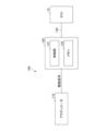
- FIG. 2 is a diagram showing an example of the configuration of the tactile presentation device 100.
- Figure 2 also shows an ECU (Electronic Control Unit) 12.
- the ECU 12 is an ECU that controls the navigation system of the vehicle 10.
- the ECU 12 may be an ECU other than the ECU that controls the navigation system.
- the control device 120 may be included in the ECU 12.
- the actuator 110 is connected to the control device 120 via a communication cable 110A, and the control device 120 is connected to the ECU 12 via a communication cable 12A.
- the drive control of the actuator 110 is performed by the control device 120.
- the communication cables 110A and 12A are, for example, communication cables conforming to standards such as CAN (Controller Area Network). Note that the communication between the actuator 110 and the ECU 12 and the control device 120 is not limited to wired communication via the communication cables 110A and 12A, and some or all of it may be wireless communication.
- the control device 120 has a control unit 121 and a memory 122.
- the control device 120 is realized by a computer including a CPU (Central Processing Unit), RAM (Random Access Memory), ROM (Read Only Memory), an input/output interface, and an internal bus.
- the control unit 121 represents the functions of the programs executed by the control device 120 as functional blocks.
- the memory 122 is a functional representation of the memory of the control device 120.
- the control unit 121 When the control unit 121 is notified of an event by the ECU 12, it reads out a vibration pattern corresponding to the type of event from the memory 122 and outputs a drive signal of the read vibration pattern to the actuator 110. As a result, the actuator 110 is driven with a vibration pattern corresponding to the type of event that has occurred.
- the memory 122 stores programs, data, etc. that the control unit 121 uses to drive the actuator 110.
- the memory 122 stores data (see FIG. 10 described later) that represents a vibration pattern corresponding to the type of event.
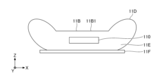
- Fig. 3 is a diagram showing an example of the configuration of a cross section of the seat 11 taken along the line A-A in Fig. 1.
- Fig. 3 shows a frame 11F of the seat 11 below the seat portion 11B.
- the X axis is an example of the first axis
- the Y axis is an example of the second axis
- the Z axis is an example of the third axis.
- the direction parallel to the X axis (X direction), the direction parallel to the Y axis (Y direction), and the direction parallel to the Z axis (Z direction) are perpendicular to each other.
- the Z direction is the vertical direction
- the +Z direction may be referred to as upward
- the -Z direction may be referred to as downward.
- a planar view refers to a view in the XY plane.
- the XY plane is parallel to the horizontal plane.
- the length, width, thickness, etc. of each part may be exaggerated to make the configuration easier to understand.
- the actuator 110 is provided inside a cushion member 11E that is disposed on the back side of the seat fabric 11D of the seat portion 11B.
- the cushion member 11E is an example of a flexible part, and an example of this is urethane foam.
- the actuator 110 may also be disposed inside the cushion member 11E provided on the back side of the seat fabric 11D of the backrest portion 11A.
- the actuator 110 is located below the surface 11B1 of the seat 11B, and is provided at approximately the center of the thickness of the cushion member 11E in the Z direction. In other words, the actuator 110 is embedded in the center of the thickness of the cushion member 11E of the seat 11B.
- both the upper and lower parts of the actuator 110 in the cushion member 11E deform, so that the user is not aware of the presence of a hard object inside the cushion member 11E.
- the position where the actuator 110 is provided on the cushion member 11E in a plan view is approximately the center of the seat portion 11B in a plan view.
- the surface 11B1 of the seat portion 11B is, for example, approximately parallel to a horizontal plane.
- the actuator 110 is driven by a drive signal output from the control device 120 (see FIG. 2) and generates vibrations. Driving the actuator 110 causes the seat 11, which is the target object, to vibrate.
- the tactile presentation device 100 vibrates the actuator 110 and transmits the vibrations to the user seated on the seat 11, thereby presenting a tactile sensation to the user.
- the actuator 110 is provided in the seat portion 11B
- ⁇ Vibration Direction of Vibrating Body of Actuator 110> to generate vibrations of a certain magnitude on the surface of an object, it is preferable to vibrate the vibrator perpendicular to the surface.
- the thickness of the cushion member 11E of the seat portion 11B of the seat 11 in the Z direction is limited, and it is difficult to vibrate the vibrator in the Z direction inside the cushion member 11E. This is because it is difficult to obtain a sufficient stroke of the vibrator in the Z direction.
- the actuator 110 vibrates the vibrating body in the X direction. That is, by vibrating in the X direction, the vibrating body of the actuator 110 generates vibrations on the surface 11B1 of the seat portion 11B, which is approximately parallel to the XY plane.
- the actuator 110 is embedded in the cushion member 11E, which has a low vibration transmission efficiency, some ingenuity is required to transmit vibrations of a certain strength to the surface 11B1 of the seat portion 11B.
- the actuator 110 employs a configuration that vibrates the vibrating body in the X direction, while being capable of generating vibrations having a Z direction component. More specifically, the actuator 110 realizes vibrations having a Z direction component by generating vibrations involving rotation in the entire actuator 110 like a cradle through vibration of the vibrating body in the X direction.
- the configuration and operation of the actuator 110 will be described in detail below.
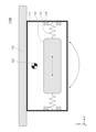
- Fig. 4A is a diagram showing an example of the configuration of actuator 110.
- Actuator 110 has housing 111, vibrating body 112, spring 113, electromagnetic coil 114, and weight 115.
- Spring 113 is an example of an elastic support section that elastically supports vibrating body 112.
- Electromagnetic coil 114 is an example of a drive section.
- Fig. 4A shows the center of gravity CG of actuator 110 when vibrating body 112 is in a stopped state.
- the housing 111 is, for example, a box-shaped member with a hollow interior, and is a case for the actuator 110.
- the housing 111 is, for example, a rectangular parallelepiped, and is composed of six walls and has six outer surfaces.
- the housing 111 can be formed of, for example, resin or metal, but is preferably formed of a metal material from the viewpoint of ensuring strength, which will be described later.
- the housing 111 is a thin plate-shaped case with a thin thickness in the Z direction, since the thickness of the cushion member 11E of the seat portion 11B in the Z direction is limited.
- the housing 111 is described as being a thin rectangular parallelepiped case, but the housing 111 only needs to be thin in the thickness direction (Z direction) of the cushion member 11E, and the overall shape does not need to be a rectangular parallelepiped.
- the housing 111 is the part that becomes the vibration generating part when the vibration generated by the vibrating body 112 is transmitted and the actuator 110 vibrates.
- the housing 111 is also provided inside the cushion member 11E of the seat portion 11B, and a load is applied in the Z direction when the user sits down. Therefore, the housing 111 only needs to be able to function as the vibration generating part for the actuator 110 and to have a strength sufficient to withstand the load.
- the vibrating body 112 is disposed inside a thin plate-like housing 111 that is thin in the Z direction, and vibrates in the X direction.
- the length of the actuator 110 in the X direction which is parallel to the vibration direction of the vibrating body 112 in a plan view, is longer than the length in the Y direction, which is perpendicular to the vibration direction of the vibrating body 112 in a plan view.
- the vibrating body 112 is composed of a permanent magnet with its longitudinal direction in the vibration direction (X direction).
- the X direction in which the vibrating body 112 vibrates is an example of a first direction.
- the ends of springs 113, one on each of the ⁇ X direction sides of the vibrating body 112, are fixed to both ends of the vibrating body 112 in the X direction.
- the vibrating body 112 vibrates so as to reciprocate in the X direction by driving electromagnetic coils 114, one on each of the ⁇ X direction sides of the vibrating body 112.
- the actuator 110 including such a vibrating body 112 is a linear actuator in which the vibrating body 112 vibrates in the X direction, and may be either a resonant type or a non-resonant type.
- the vibrating body 112 may have a shape that does not have a longitudinal direction in the vibration direction (X direction).
- the vibrating body 112 may be square in a plan view, and may have a configuration in which the longitudinal direction is in the Y direction and the transverse direction is in the X direction.
- the actuator 110 adopts a moving magnet type configuration in which the vibrating body 112 is a permanent magnet and the electromagnetic coil 114 is fixed to the housing 111 side
- the moving magnet type actuator 110 has the advantage that it can obtain larger vibrations than the moving coil type.
- the actuator 110 may adopt a moving coil type configuration in which the vibrating body 112 is composed of an electromagnetic coil. This configuration will be described later together with the electromagnetic coil 114.
- the actuator 110 may also be configured such that, for example, an electromagnetic coil is provided on the lower side, upper side, or side of the vibrating body 112 when it is in a stopped state, so that the vibrating body 112 vibrates in the X direction.
- the actuator 110 may also be configured to vibrate the vibrating body 112 in the Y direction.
- the longitudinal direction of the vibrating body 112 is the Y direction.
- the springs 113 are provided one on each of the ⁇ X direction sides of the vibrating body 112. One end of each spring 113 is fixed to an end of the vibrating body 112 in the X direction, and the other end is fixed to an inner wall of the housing 111.
- the springs 113 are elastic members having elasticity that allows them to expand and contract in the X direction. It is sufficient for the springs 113 to be capable of elastically supporting the vibrating body 112 with respect to the housing 111 while the vibrating body 112 is capable of vibrating in the X direction.
- the springs 113 may be, for example, coil springs, leaf springs, or the like.
- the electromagnetic coil 114 is wound when viewed in the YZ plane, and a spring 113 is passed through the center of the electromagnetic coil 114.
- the spring 113 is fixed to the inner wall of the housing 112 with the spring 113 passing through the center of the electromagnetic coil 114.
- the electromagnetic coil 114 is connected to the control device 120 via a cable or the like.
- the electromagnetic coil 114 generates a magnetic field capable of magnetically attracting the vibrating body 112, which is made up of a permanent magnet, in the X direction, by current control performed by the control unit 121.
- the control unit 121 periodically changes the polarity of the current flowing through the electromagnetic coil 114, causing a magnetic attraction force to act between the vibrating body 112, which is made up of a permanent magnet, and the electromagnetic coil 114, causing the vibrating body 112 to vibrate in the X direction.
- the vibrating body 112 is an electromagnetic coil, and a permanent magnet is fixed to the housing 111 instead of the electromagnetic coil 114.
- the permanent magnet fixed to the housing 111 instead of the electromagnetic coil 114 is an example of a drive unit.
- the driving unit is an electromagnetic coil 114 that is provided on the housing 111 side and can magnetically attract the vibrating body 112 in the longitudinal direction and can generate a magnetic attraction force between the vibrating body 112 that is made up of a permanent magnet.
- the driving unit is provided on the housing 111 side and can magnetically attract the vibrating body 112 in the longitudinal direction and is made up of a permanent magnet that can generate a magnetic attraction force between the vibrating body 112 that is made up of an electromagnetic coil.
- weight 115 is provided on the back surface (inner surface) of the wall on the upper surface side of housing 111. Therefore, as an example, weight 115 is located above vibrating body 112.
- the up-down direction (Z direction) is an example of a second direction intersecting with the vibration direction (X direction, an example of a first direction) of vibrating body 112.
- the back surface of the wall on the upper surface side of housing 111 on which weight 115 is provided is an example of a portion of housing 111 located on the second direction side.
- the second direction is not limited to the up-down direction (Z direction), but may be the short side direction (Y direction) of the vibrating body 112.
- the weight 115 may be provided on the back surface (inner surface) of the bottom wall or side wall of the housing 111.
- the weight 115 may also be provided on the surface of the top wall, bottom wall, or side wall of the housing 111. In this way, the weight 115 is provided on one surface of the wall of the housing 111.
- the center of gravity CG of the actuator 110 is offset from the center of the actuator 110 and from the center of gravity of the vibrating body 112.
- the weight 115 is provided to decenter the center of gravity CG of the actuator 110, thereby generating a cradle-like vibration in the entire actuator 110 when the vibrating body 112 vibrates in the X direction.
- the center of gravity CG is the center of gravity of the entire actuator 110 when the vibrating body 112 is stationary.
- the actuator 110 is provided inside the cushion member 11E, when the vibrating body 112 starts vibrating in the X direction, the cushion member 11E around the actuator 110 bends. Therefore, the center of gravity CG of the actuator 110 is in the position shown in FIG. 4A when the vibrating body 112 is at rest, but when the vibrating body 112 starts vibrating, it shifts from the position shown in FIG. 4A. Even when the vibrating body 112 is vibrating, the center of gravity CG of the actuator 110 is eccentric.
- the actuator 110 When the actuator 110 starts vibrating from a stopped state of the vibrating body 112, the axis passing through the center of gravity CG in the Y direction at the position shown in Figure 4A becomes the axis on which a rotational moment is generated and starts vibrating. Then, as the center of gravity CG shifts from the position shown in Figure 4A, the actuator 110 repeatedly performs vibrations including a rotational moment in a state in which the center of gravity CG is eccentric. In Figure 4A, the direction of the vibration including the rotational moment is indicated by a double-headed arrow.
- Such vibrations include a Z-direction component. That is, even if there is a constraint such as cushion member 11E, which limits the thickness in the Z direction and prevents vibrating body 112 from vibrating in the Z direction, actuator 110 can generate vibrations that include a Z-direction component perpendicular to surface 11B1 of seat portion 11B. Actuator 110 oscillates as a whole, vibrating in the X direction while also vibrating in the Z direction.
- the center of gravity CG of the actuator 110 becomes eccentric by shifting the position of the center of gravity of the vibrating body 112 relative to the center of the housing 111, but by attaching the weight 115 to the housing 111, the center of gravity CG of the actuator 110 can be shifted more significantly relative to the center of the actuator 110.
- the rotational moment can be significantly increased, and sufficient vibration intensity can be obtained when presenting vibrations to a user seated on the seat 11B.
- a rotational moment of a level that can be used as a tactile presentation device 100 can be generated.
- the heavier the weight 115 the greater the degree of eccentricity of the center of gravity CG of the actuator 110 when stopped, and the greater the Z-direction component of the vibration. For this reason, it is better for the weight 115 to be heavier, and it is believed that the Z-direction component of the vibration will be greater if the weight 115 is heavier than the vibrating body 112.
- the weight 115 is provided on one surface of the wall portion of the housing 111, located in the thickness direction (Z direction) of the cushion member 11E (flexible portion). This makes it possible to increase the Z direction component of the eccentricity of the center of gravity CG of the actuator 110. As a result, the Z direction component of the vibration of the actuator 110 increases, and a haptic sensation can be presented with a larger vibration.
- the center of gravity CG of the weight 115 may be shifted from the center of gravity CG of the vibrating body 112 in a direction horizontally away from the end of the seat 11B having the cushion member 11E.
- the Z-direction component of the vibration is biased toward the center of the seat 11B in a plan view, and the propagation of the vibration toward the center of the seat 11B in a plan view increases, making it easier for the vibration to be transmitted to the occupant.
- the weight 115 shown in FIG. 4A is separate from the housing 111
- the weight 115 may be a part of the housing 111 and may be formed by folding a part of the wall of the housing 111.
- the wall on the top side of the housing 111 may be made long and folded to form the weight 115 shown in FIG. 4A.
- the weight 115 can be easily formed by folding.
- the above-mentioned portion of the housing 111 may be formed from a material having a higher specific gravity than the remaining portion of the housing 111.
- the weight 115 By forming the weight 115 from a material having a higher specific gravity, the weight 115 can be easily formed and can also be formed thin.
- Fig. 4B is a diagram for explaining the torque that rotates the actuator 110.
- a torque T applied to the center of gravity CG of the actuator 110 when the vibration of the vibrating body 112 stops will be explained.
- Fig. 4B shows the center of gravity CG1 of the weight 115 and the center of gravity CG2 of the vibrating body 112.
- the mass of weight 115 is m 1
- the mass of vibrating body 112 is m 2.
- the distance between the center of gravity CG of actuator 110 and the center of gravity CG1 of weight 115 is l 1
- the distance between the center of gravity CG of actuator 110 and the center of gravity CG2 of vibrating body 112 is l 2.
- the force generated at the center of gravity CG2 when vibrating body 112 vibrates is F.
- Fig. 4B shows, as an example, a state in which vibrating body 112 vibrates in the +X direction.
- the position of the center of gravity CG of actuator 110 is determined by dividing the distance l between vibrating body 112 and weight 115 by mass m1 of weight 115 and mass m2 of vibrating body 112. To increase torque T, distance l2 should be increased, and to achieve this, mass m1 of weight 115 should be increased.
- ⁇ Modifications of weight 115> 4C is a diagram showing an example of the configuration of an actuator 110M according to a modified example of the embodiment. In the actuator 110M shown in FIG.
- the length of weight 115 in the X direction is, for example, longer than the length of housing 111 in the X direction.
- weight 115 is longer than housing 111, which increases the degree of eccentricity of center of gravity CG of actuator 110 when stopped, and increases the Z direction component of vibration.
- the length of weight 115 in the X direction can be made longer than the length of housing 111 in the X direction.
- the area of weight 115 is, for example, larger than the area of housing 111.
- the area of weight 115 is, for example, larger than the area of housing 111.
- the area of the weight 115 is, for example, larger than the area of the housing 111, and the weight 115 is disposed so as to enclose the housing 111 in a plan view.
- Enclosing the housing 111 in a plan view means that the outer edge of the weight 115 is located outside the outer edge of the housing 111 in a plan view.
- the area of the weight 115 larger than the area of the housing 111 and increasing the Z-direction component of the eccentricity of the center of gravity CG of the actuator 110, when the vibrating body 112 vibrates, the area through which the vibration propagates to the cushion member 11E increases, and the Z-direction component of the vibration propagating to the surface 11B1 of the seat portion 11B increases.
- the weight 115 may also be attached to the housing 111 via a support.
- the support is a member that is located between the housing 111 and the weight 115 and fixes the weight 115 to the housing 111 when the weight 115 is separated from the housing 115.
- a spacer can be used as such a support.
- the actuator 110M shown in FIG. 4C by sandwiching a spacer between the housing 111 and the weight 115, the distance between the weight 115 and the vibrating body 112 can be increased. As a result, even if the weight 115 and the vibrating body 112 have the same weight, the center point of the generation of the rotational moment can be shifted away from the vibrating body 112, so that a large cradle vibration can be generated.
- ⁇ Simulation results> 5A is a diagram showing an example of a simulation result, in which the acceleration of the vibration of the actuator 110 obtained when the vibration frequency of the vibrating body 112 is changed is calculated by simulation.
- the comparative actuator (4) does not include a weight 115, but because the vibrating body vibrates in the Z direction, the vibration acceleration rises from 50 Hz and peaks at 200 Hz.
- the peak value of the acceleration was approximately twice that of (1), which was the largest among (1) to (3).
- the comparative actuator (3) has a configuration in which the weight 115 is omitted from the actuator 110, so the center of gravity of the actuator is approximately the same as the center of gravity of the vibrating body 112. Since almost no rotational moment is obtained, the vibration acceleration was the smallest.
- the vibration acceleration obtained from about 100 Hz to about 170 Hz was the same as that of the comparative actuator in (4) (where the vibrating body vibrates in the Z direction).
- the actuator 110 (2) had a smaller vibration acceleration than the actuator 110 (1) because the weight 115 was made of ABS resin and was light, but at approximately 170 Hz, the vibration acceleration was approximately twice that of the comparative actuator (3).
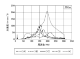
- ⁇ Actual measurement results> 5B is a diagram showing an example of the results of actual measurements, in which the acceleration of the actuator 110 obtained when the vibration frequency of the vibrating body 112 was changed was measured.
- the frequency characteristics of the vibration acceleration of the actuator 110 were measured for (1A) an actuator 110 with the weight 115 being one iron plate, (1B) an actuator 110 with the weight 115 being two iron plates, and (1C) an actuator 110 with the weight 115 being three iron plates.
- the frequency characteristics of the vibration acceleration were measured for (3) a comparative actuator in which the weight 115 was omitted, and (4) a comparative actuator in which the weight 115 was omitted and the vibrating body vibrated in the Z direction.
- a three-axis acceleration sensor was used to measure the vibration acceleration.
- the comparative actuator (4) does not include a weight 115, but because the vibrating body vibrates in the Z direction, a large vibration acceleration was obtained.
- the vibration acceleration started at 50 Hz and peaked at about 200 Hz.
- the peak acceleration value was about twice that of (1B), which was the largest among (1A) to (1C) and (3).
- the comparative actuator (3) has a configuration in which the weight 115 is omitted from the actuator 110, so the center of gravity of the actuator is approximately the same as the center of gravity of the vibrating body 112. Since almost no rotational moment is obtained, the vibration acceleration was the smallest.
- the actuator 110 of (1A) has a weight 115 of a single iron plate. From about 120 Hz to about 180 Hz, a vibration acceleration greater than that of the comparative actuator (3) (without weight 115) was obtained, and the peak value at about 175 Hz was about 1.5 times that of (3) at about 220 Hz.
- the actuator 110 of (1B) has a weight 115 consisting of two iron plates, which is twice as heavy as the weight 115 of (1A). From about 120 Hz to about 160 Hz, a vibration acceleration was obtained that was about twice as large as that of the actuator 110 of (1A) and equivalent to that of the comparative actuator (4) (Z-direction vibration). The peak value of the vibration acceleration at about 160 Hz was larger than the peak value at about 140 Hz of the actuator 110 of (1C).
- the actuator 110 in (1C) has a weight 115 made of three iron plates, which is three times heavier than the weight 115 in (1A). From about 100 Hz to about 140 Hz, a vibration acceleration equivalent to that of the comparative actuator in (4) (Z-direction vibration) was obtained.
- Fig. 6 is a diagram showing an example of a simulation model used to obtain the simulation results of the sound pressure distribution.
- the positions of the actuator 110 and the two microphones 20A and 20B that measured the sound pressure are indicated by white circles.
- the actuator 110 is located at a position of 0 m in the Z direction, and the length in the X direction is, for example, 60 mm.
- the position of microphone 20A is 0.5 m from actuator 110 in the -X direction and 1 m from actuator 110 in the +Z direction.
- Microphone 20B is 0.5 m from actuator 110 in the +X direction and 1 m from actuator 110 in the +Z direction.
- the space in which the simulation was performed was a space ranging from 1 m in the +Z direction from the actuator 110 to 1 m in the X direction between the microphones 20A and 20B, as shown in FIG. 6.
- the speed of sound was set to 343.24 m/s, which is the speed of sound at 1 atmosphere and 20°C.
- the frequencies of the drive signals driving the pair of actuators 110 were set to 50 Hz, 100 Hz, 200 Hz, and 400 Hz, and the sound pressure distribution of the sound generated from the bottom portion 11B of the seat 11 was calculated, resulting in the sound pressure distributions shown in FIG. 7A to FIG. 7D. Note that the bottom portion 11B of the seat 11 is omitted in FIG. 6.
- FIGS. 7A to 7D are diagrams showing an example of the simulation results.
- 7A to 7D show the sound pressure distribution of the sound generated from the bottom portion 11B of the seat 11 when the actuator 110 is driven.
- the range of sound pressure from low to high is shown in stages using shades of gray (gradation) between white and black.
- the sound pressure distribution shown in FIGS. 7A to 7D is the distribution at the timing when the amplitude of the sound pressure is maximum.
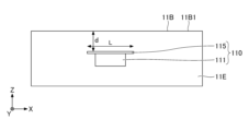
- Fig. 8A is a diagram showing the length L in the X direction of the weight 115 of the actuator 110 and the depth d from the surface 11B1 of the seat portion 11B.
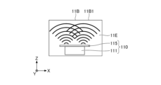
- Fig. 8B is a diagram showing an example of the Z direction component of the vibration when the depth d is large.
- Fig. 8C is a diagram showing an example of the Z direction component of the vibration when the depth d is shallow.
- the Z-direction component of the vibration generated at the +X-direction end of weight 115 and the Z-direction component of the vibration generated at the -X-direction end of weight 115 are considered to be in opposite phase because vibrating body 112 vibrates in the X-direction.
- the depth d is shallow, as shown in FIG. 8C, it is believed that the Z-direction components of the vibrations generated at the +X-direction end and the -X-direction end of the weight 115 will not combine inside the cushion member 11E, but will reach the surface 11B1 of the seat portion 11B.
- d ⁇ L/2 holds, it is believed that the Z-direction components of the vibrations generated at the +X-direction end and -X-direction end of the weight 115 are less likely to combine inside the cushion member 11E, and the cancellation of the vibrations can be suppressed. For this reason, it is preferable to provide the actuator 110 inside the cushion member 11E so that d ⁇ L/2 holds for the length L of the weight 115 of the actuator 110 in the X-direction and the depth d from the surface 11B1 of the seat portion 11B.
- the vibration generating device includes a housing 111, a vibrating body 112 housed in the housing 111 and composed of a permanent magnet or an electromagnetic coil, a spring (elastic support section) 113 that elastically supports the vibrating body 112, a drive section that is provided in the housing 111 and composed of an electromagnetic coil 114 capable of generating a force that magnetically attracts the vibrating body 112 composed of a permanent magnet in a first direction, or composed of a permanent magnet that can generate a force that magnetically attracts the vibrating body 112 composed of an electromagnetic coil in the first direction, and a weight 115 provided in a portion of the housing 111 located on a side in a direction intersecting with the first direction.
- a rotational moment can be generated, and a cradle vibration (arc-shaped vibration) that vibrates in two directions, the up-down (vertical) direction and the left-right (horizontal) direction, can be generated.
- a vibration generating device in which the vibrating body vibrates in a direction along the surface that generates the vibrations, and which can generate vibrations in a direction perpendicular to the surface that generates the vibrations.
- the weight 115 may also be heavier than the vibrating body 112. This increases the degree of eccentricity of the center of gravity CG of the actuator 110, allowing the Z-direction component of the vibration to be increased.
- the weight 115 may also be provided on one side of the wall of the housing 111. By providing the weight 115 on one side of the housing 111 away from the vibrating body 112, the weight 115 can be easily fixed away from the vibrating body 112.
- the weight 115 may be attached to the housing 111 via a support.
- the degree of eccentricity of the center of gravity of the actuator 110 increases, and the Z-direction component of the vibration can be increased due to a larger rotational moment.
- the Z-direction component of the vibration can be increased due to a larger rotational moment.
- the housing 111 may be formed of a metal material and may be a part of the housing 111.
- the weight 115 and the housing 111 can be integrated, and there is no need to provide the weight 115 separately from the housing 111, allowing for a simple configuration.
- the weight 115 may also be formed by folding a portion of the housing 111.
- the weight 115 can be easily formed by folding a metal plate or the like.
- a portion of the housing 111 may be made of a material that has a higher specific gravity than the remaining portions of the housing 111. By making the weight 115 out of a material with a higher specific gravity, it is easy to form the weight 115.
- the tactile presentation device 100 includes a housing 111, a vibrator 112 housed in the housing 111 and composed of a permanent magnet or an electromagnetic coil, a spring (elastic support part) 113 that elastically supports the vibrator 112, a drive part composed of an electromagnetic coil 114 provided in the housing 111 and capable of generating a force that magnetically attracts the vibrator 112 composed of a permanent magnet in a first direction, or a permanent magnet that can generate a force that magnetically attracts the vibrator 112 composed of an electromagnetic coil in the first direction, a weight 115 provided in a part of the housing 111 located in a direction intersecting with the first direction, and a control part 121 that controls the drive of the electromagnetic coil.
- a rotational moment can be generated with a simple configuration in which the weight 115 is provided in a part of the housing 111 located in a direction intersecting with the first direction, and a cradle vibration (arc-shaped vibration) that vibrates in two directions, up and down (vertical) and left and right (horizontal).
- a cradle vibration arc-shaped vibration
- a tactile presentation device in which the vibrator vibrates in a direction along the surface that generates the vibrations, and which can generate vibrations in a direction perpendicular to the surface that generates the vibrations.
- the seat system 200 includes a seat 11 having a seat portion 11B and a backrest portion 11A, and a tactile presentation device 100.
- the tactile presentation device 100 includes a housing 111 provided on a cushion member 11E (flexible portion) of the seat portion 11B or the backrest portion 11A of the seat 11, a vibrating body 112 housed in the housing 111 and composed of a permanent magnet or an electromagnetic coil, a spring (elastic support portion) 113 that elastically supports the vibrating body 112, a drive unit provided in the housing 111 and composed of an electromagnetic coil 114 capable of generating a force that magnetically attracts the vibrating body 112 composed of a permanent magnet in a first direction, or composed of a permanent magnet that can generate a force that magnetically attracts the vibrating body 112 composed of an electromagnetic coil in the first direction, a weight 115 provided in a portion of the housing 111 located in a direction intersecting the first direction, and a control unit 121 that controls the drive of the electromagnetic coil.
- a rotational moment can be generated by simply locating the weight 115 on the part of the housing 111 that is located in a direction that intersects with the first direction, and a cradle vibration (arc-shaped vibration) that vibrates in two directions, up and down (vertical) and left and right (horizontal), can be generated.
- a cradle vibration arc-shaped vibration
- the center of gravity of the weight 115 may be shifted from the center of gravity of the vibrating body 112 in a direction horizontally away from the end of the seat portion 11B or backrest portion 11A having the cushion member 11E (flexible portion).
- the Z-direction component of the vibration is biased toward the center of the seat portion 11B in a planar view, and the propagation of the vibration toward the center of the seat portion 11B in a planar view increases, making it easier for the vibration to be transmitted to the occupant.
- the area of the weight 115 may be larger than the area of the housing 111.
- the area of the weight 115 may be larger than the area of the housing 111.
- the weight 115 may also be provided on one surface of the wall of the housing 111 that is located in the thickness direction of the cushion member 11E (flexible portion). This increases the Z-direction component of the eccentricity of the center of gravity CG of the actuator 110. As a result, the Z-direction component of the vibration of the actuator 110 increases, and a haptic sensation can be presented with a larger vibration.
- Vehicle 11 Seat (an example of an object) 11A Backrest 11B Seat 11B1 Surface 11E Cushion member 100 Tactile presentation device 110
- Actuator (an example of a vibration generating device)
- Housing 112 Vibration body
- Spring an example of an elastic support portion
- Electromagnetic coil (an example of a driving unit)
- Weight 120
- Control unit 122
- Memory 200 Seat system
Landscapes
- Engineering & Computer Science (AREA)
- Mechanical Engineering (AREA)
- Physics & Mathematics (AREA)
- General Physics & Mathematics (AREA)
- Evolutionary Computation (AREA)
- Medical Informatics (AREA)
- Software Systems (AREA)
- Computer Vision & Pattern Recognition (AREA)
- Health & Medical Sciences (AREA)
- Automation & Control Theory (AREA)
- Artificial Intelligence (AREA)
- Aviation & Aerospace Engineering (AREA)
- Transportation (AREA)
- Human Computer Interaction (AREA)
- Electromagnetism (AREA)
- Apparatuses For Generation Of Mechanical Vibrations (AREA)
Priority Applications (4)
| Application Number | Priority Date | Filing Date | Title |
|---|---|---|---|
| DE112024001641.3T DE112024001641T5 (de) | 2023-04-07 | 2024-02-27 | Vibrationsgenerator, taktile Darstellungsvorrichtung und Sitzsystem |
| CN202480021572.XA CN120936444A (zh) | 2023-04-07 | 2024-02-27 | 振动产生装置、触觉提示装置及座椅系统 |
| JP2025512444A JPWO2024209841A1 (cg-RX-API-DMAC7.html) | 2023-04-07 | 2024-02-27 | |
| US19/314,388 US20250381900A1 (en) | 2023-04-07 | 2025-08-29 | Vibration generator, tactile presentation device, and seat system |
Applications Claiming Priority (2)
| Application Number | Priority Date | Filing Date | Title |
|---|---|---|---|
| JP2023-062800 | 2023-04-07 | ||
| JP2023062800 | 2023-04-07 |
Related Child Applications (1)
| Application Number | Title | Priority Date | Filing Date |
|---|---|---|---|
| US19/314,388 Continuation US20250381900A1 (en) | 2023-04-07 | 2025-08-29 | Vibration generator, tactile presentation device, and seat system |
Publications (1)
| Publication Number | Publication Date |
|---|---|
| WO2024209841A1 true WO2024209841A1 (ja) | 2024-10-10 |
Family
ID=92972112
Family Applications (1)
| Application Number | Title | Priority Date | Filing Date |
|---|---|---|---|
| PCT/JP2024/007165 Ceased WO2024209841A1 (ja) | 2023-04-07 | 2024-02-27 | 振動発生装置、触覚提示装置、及び、シートシステム |
Country Status (5)
| Country | Link |
|---|---|
| US (1) | US20250381900A1 (cg-RX-API-DMAC7.html) |
| JP (1) | JPWO2024209841A1 (cg-RX-API-DMAC7.html) |
| CN (1) | CN120936444A (cg-RX-API-DMAC7.html) |
| DE (1) | DE112024001641T5 (cg-RX-API-DMAC7.html) |
| WO (1) | WO2024209841A1 (cg-RX-API-DMAC7.html) |
Citations (6)
| Publication number | Priority date | Publication date | Assignee | Title |
|---|---|---|---|---|
| JP2011125843A (ja) * | 2009-09-29 | 2011-06-30 | Sanyo Electric Co Ltd | 加速度発生デバイス |
| JP2016082536A (ja) * | 2014-10-22 | 2016-05-16 | 日本電信電話株式会社 | 加速度発生装置および情報呈示方法 |
| WO2016157264A1 (ja) * | 2015-03-31 | 2016-10-06 | ソニー株式会社 | 力覚提示装置 |
| JP2021030188A (ja) * | 2019-08-29 | 2021-03-01 | 日本電産サンキョー株式会社 | 電子機器 |
| WO2021131580A1 (ja) * | 2019-12-27 | 2021-07-01 | アルプスアルパイン株式会社 | 触覚呈示装置 |
| WO2022014135A1 (ja) * | 2020-07-14 | 2022-01-20 | アルプスアルパイン株式会社 | 車両システム及び振動発生装置 |
Family Cites Families (2)
| Publication number | Priority date | Publication date | Assignee | Title |
|---|---|---|---|---|
| JP6870996B2 (ja) | 2017-01-27 | 2021-05-12 | 日本電産コパル株式会社 | 振動モータ |
| JP2023062800A (ja) | 2021-10-22 | 2023-05-09 | Apb株式会社 | 電池用電極製造装置及び電池用電極製造方法 |
-
2024
- 2024-02-27 JP JP2025512444A patent/JPWO2024209841A1/ja active Pending
- 2024-02-27 WO PCT/JP2024/007165 patent/WO2024209841A1/ja not_active Ceased
- 2024-02-27 CN CN202480021572.XA patent/CN120936444A/zh active Pending
- 2024-02-27 DE DE112024001641.3T patent/DE112024001641T5/de active Pending
-
2025
- 2025-08-29 US US19/314,388 patent/US20250381900A1/en active Pending
Patent Citations (6)
| Publication number | Priority date | Publication date | Assignee | Title |
|---|---|---|---|---|
| JP2011125843A (ja) * | 2009-09-29 | 2011-06-30 | Sanyo Electric Co Ltd | 加速度発生デバイス |
| JP2016082536A (ja) * | 2014-10-22 | 2016-05-16 | 日本電信電話株式会社 | 加速度発生装置および情報呈示方法 |
| WO2016157264A1 (ja) * | 2015-03-31 | 2016-10-06 | ソニー株式会社 | 力覚提示装置 |
| JP2021030188A (ja) * | 2019-08-29 | 2021-03-01 | 日本電産サンキョー株式会社 | 電子機器 |
| WO2021131580A1 (ja) * | 2019-12-27 | 2021-07-01 | アルプスアルパイン株式会社 | 触覚呈示装置 |
| WO2022014135A1 (ja) * | 2020-07-14 | 2022-01-20 | アルプスアルパイン株式会社 | 車両システム及び振動発生装置 |
Also Published As
| Publication number | Publication date |
|---|---|
| JPWO2024209841A1 (cg-RX-API-DMAC7.html) | 2024-10-10 |
| US20250381900A1 (en) | 2025-12-18 |
| DE112024001641T5 (de) | 2026-03-12 |
| CN120936444A (zh) | 2025-11-11 |
Similar Documents
| Publication | Publication Date | Title |
|---|---|---|
| US11575302B2 (en) | Vibration actuator and mobile electronic apparatus including the same | |
| JP7093013B2 (ja) | 振動アクチュエータ、ウェアラブル端末及び着信通知機能デバイス | |
| US11069466B2 (en) | Vibration actuator and vibration providing apparatus | |
| EP3321127B1 (en) | Vibration generating device | |
| US20120153748A1 (en) | Vibration generator | |
| JPWO2008146678A1 (ja) | 圧電アクチュエータ及び電子機器 | |
| CN108475106B (zh) | 触摸界面模块和用于生成触觉反馈的方法 | |
| CN101631710B (zh) | 车辆用振动器组件 | |
| CN113410969B (zh) | 振动马达 | |
| JP2007300426A (ja) | 圧電振動子およびこれを備えた圧電振動発生装置 | |
| CN112018991B (zh) | 致动器及触觉设备 | |
| JP7300524B2 (ja) | 触覚呈示装置 | |
| CN211830531U (zh) | 线性振动马达和电子设备 | |
| US8776938B2 (en) | Active vibratory control device, vehicle comprising such a device and active mounting base for such a device | |
| WO2019021969A1 (ja) | 振動発生装置 | |
| WO2024209841A1 (ja) | 振動発生装置、触覚提示装置、及び、シートシステム | |
| JP7410705B2 (ja) | アクチュエータおよび触覚デバイス | |
| CN114902165A (zh) | 操作装置 | |
| JP6871082B2 (ja) | リニア振動モータ及び電子機器 | |
| CN113382808B (zh) | 振动生成装置 | |
| JP2020146594A (ja) | 振動発生装置 | |
| JPWO2024209841A5 (cg-RX-API-DMAC7.html) | ||
| JP2026010409A (ja) | 振動システム、振動部材、および移動体 | |
| JP2022020185A (ja) | アクチュエータおよび触覚デバイス | |
| JP2019127170A (ja) | 振動付与装置 |
Legal Events
| Date | Code | Title | Description |
|---|---|---|---|
| 121 | Ep: the epo has been informed by wipo that ep was designated in this application |
Ref document number: 24784637 Country of ref document: EP Kind code of ref document: A1 |
|
| ENP | Entry into the national phase |
Ref document number: 2025512444 Country of ref document: JP Kind code of ref document: A |
|
| WWE | Wipo information: entry into national phase |
Ref document number: 2025512444 Country of ref document: JP |
|
| WWE | Wipo information: entry into national phase |
Ref document number: 112024001641 Country of ref document: DE |
|
| WWP | Wipo information: published in national office |
Ref document number: 112024001641 Country of ref document: DE |
|
| 122 | Ep: pct application non-entry in european phase |
Ref document number: 24784637 Country of ref document: EP Kind code of ref document: A1 |