WO2024209674A1 - 表面実装機 - Google Patents
表面実装機 Download PDFInfo
- Publication number
- WO2024209674A1 WO2024209674A1 PCT/JP2023/014352 JP2023014352W WO2024209674A1 WO 2024209674 A1 WO2024209674 A1 WO 2024209674A1 JP 2023014352 W JP2023014352 W JP 2023014352W WO 2024209674 A1 WO2024209674 A1 WO 2024209674A1
- Authority
- WO
- WIPO (PCT)
- Prior art keywords
- head
- component
- nozzle
- chip
- suction
- Prior art date
- Legal status (The legal status is an assumption and is not a legal conclusion. Google has not performed a legal analysis and makes no representation as to the accuracy of the status listed.)
- Ceased
Links
Images






Classifications
-
- H—ELECTRICITY
- H05—ELECTRIC TECHNIQUES NOT OTHERWISE PROVIDED FOR
- H05K—PRINTED CIRCUITS; CASINGS OR CONSTRUCTIONAL DETAILS OF ELECTRIC APPARATUS; MANUFACTURE OF ASSEMBLAGES OF ELECTRICAL COMPONENTS
- H05K13/00—Apparatus or processes specially adapted for manufacturing or adjusting assemblages of electric components
- H05K13/04—Mounting of components, e.g. of leadless components
-
- H—ELECTRICITY
- H05—ELECTRIC TECHNIQUES NOT OTHERWISE PROVIDED FOR
- H05K—PRINTED CIRCUITS; CASINGS OR CONSTRUCTIONAL DETAILS OF ELECTRIC APPARATUS; MANUFACTURE OF ASSEMBLAGES OF ELECTRICAL COMPONENTS
- H05K13/00—Apparatus or processes specially adapted for manufacturing or adjusting assemblages of electric components
- H05K13/08—Monitoring manufacture of assemblages
Definitions
- the technology disclosed in this specification relates to technology that improves the pickup position accuracy of parts.
- Patent Document 1 discloses the following regarding a component mounting device that removes bare chips from a wafer and mounts them on a substrate.
- the component mounting device includes a wafer head that removes bare chips from a wafer, a mounting head that receives the bare chip removed by the wafer head from the wafer head at a specified transfer position and mounts it on a board, a fixed camera that images the bare chip held by the mounting head, and a control device that controls each head.
- This control device determines the amount of suction deviation of the bare chip relative to the mounting head based on the component image captured by the fixed camera, and based on this deviation, corrects the removal position (target suction position) when the wafer head removes the subsequent bare chip from the wafer.
- the surface mounter includes a supply unit, an intermediate stage, a first head that transfers components from the supply unit onto the intermediate stage, a second head that picks up the components from the intermediate stage and mounts them on a board, a photographing device, and a control unit.
- the second head includes a position reference unit, and the control unit corrects the position of at least one of the component and the second head based on the image capture result of the position reference unit by the imaging device so as to reduce the pickup position error of the second head relative to the component center of the component transferred to the relay stage.
- This configuration makes it possible to reduce the pickup position error of the second head relative to the center of the component. This makes it possible to improve the pickup position accuracy of the component.
- the surface mount machine may be embodied as follows.
- the second head may have a nozzle shaft having a suction nozzle at its tip, the position reference unit may be the tip of the suction nozzle, and the control unit may calculate an amount of deviation of the tip of the suction nozzle from the center of rotation based on the photographing result of the suction nozzle, and correct the transfer position of the component with respect to the relay stage based on the amount of deviation.
- the transfer position of the component can be corrected in accordance with the nozzle eccentricity.
- the surface mount machine may be embodied as follows.
- the position reference unit may be a mark provided on the second head, and the control unit may calculate an amount of deviation of the position of the second head from a reference position based on an image of the mark, and correct a movement target point when the second head moves from the relay stage to a pickup operation position where the component is picked up based on the calculated amount of deviation. With this configuration, an error in the pickup operation position of the second head can be suppressed.
- the surface mount machine may be embodied as follows.
- the second head may be a head unit having a plurality of nozzle shafts each having a suction nozzle at its tip, and the control unit may correct a movement target point when the head unit moves to the suction operation position based on the image capturing result of the mark. With this configuration, it is possible to reduce an error in the suction operation position of the head unit.
- the surface mount machine may be embodied as follows.
- the control unit may correct the transfer position with respect to the relay stage for each component. With this configuration, the transfer position with respect to the relay stage can be adjusted for each component.
- the surface mount machine may be embodied as follows.
- the second head may be a head unit having a plurality of nozzle shafts each having a suction nozzle at its tip, and the control unit may correct a transfer position of the component with respect to the relay stage based on a pitch between the nozzle shafts. With this configuration, the transfer position of the component can be adjusted according to the pitch between the nozzle shafts.
- the surface mount machine may be embodied as follows. Position correction may be performed for both the component and the second head.
- the surface mount machine may be embodied as follows.
- the surface mounter may be a flip chip bonder that turns over the flip chip supplied from the supply unit and mounts it on the substrate.
- This configuration can improve the accuracy of component pickup positioning in surface mounting machines that mount components on boards.
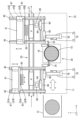
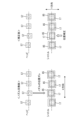
- FIG. FIG. 2 is an enlarged view of a portion of the surface mounter.
- FIG. 2 is a front view of the head unit.
- FIG. FIG. 13 is a diagram showing the reversing operation of a flipper.
- 13A and 13B are diagrams showing the chip transfer operation by a traverser.
- FIG. 13 is a diagram showing the receiving and removing positions of the shuttle.
- FIG. 2 is a block diagram showing an electrical configuration of the surface mounter.
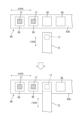
- 11A and 11B are diagrams illustrating a suction operation of a chip by a suction nozzle.
- FIG. 11 is an explanatory diagram of the amount of misalignment of the nozzle center.
- 11A and 11B are diagrams illustrating a suction operation of a chip by a suction nozzle.
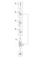
- FIG. 4 is a diagram showing the positional relationship between a suction nozzle and a component. 13 is a flowchart of component suction control.
- FIG. 11 is a diagram showing a displacement of the head unit.
- 4A and 4B are diagrams showing a suction operation position and a mounting operation position of the head unit.
- 11A and 11B are diagrams illustrating the operation of photographing a mark by a recognition camera.
- FIG. 13 is a diagram showing a result of mark recognition.
- FIG. 4 is a diagram showing the relationship between a component and a suction nozzle.
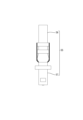
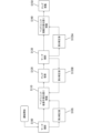
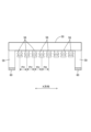
- FIG. 2 is a block diagram relating to the control of the suction position and the control of the mounting position of the chip. Diagram showing shaft pitch
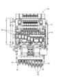
- Fig. 1 is a plan view of a surface mounting machine 10
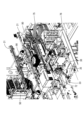
- Fig. 2 is a perspective view of the surface mounting machine 1.
- the surface mounting machine 10 is a flip chip bonder.
- a flip chip is a semiconductor chip having electrodes on its surface.
- the transport direction of the substrate P (the long side direction of the base 11, the left-right direction in FIG. 1) is the X direction
- the direction perpendicular to the transport direction of the substrate P (the short side direction of the base 11, the up-down direction in FIG. 1) is the Y direction
- the height direction (the direction perpendicular to the paper surface in FIG. 1) is the Z direction.
- the surface mounter 10 includes a base 11, a transport conveyor 20, a wafer supply unit 30, a head unit 50, a traverser 70, a shuttle 80, a recognition camera 90, and a controller 100.
- the wafer supply unit 30 is an example of a supply unit
- the shuttle 80 is an example of a relay stage
- the traverser 70 is an example of a first head
- the head unit is an example of a second head
- the recognition camera 90 is an example of an imaging device.
- the transport conveyor 20 is disposed in the center of the base 11.
- the transport conveyor 20 is equipped with a pair of transport belts 21 that are driven in a circular motion in the X-direction, and transports the substrate P on the transport belts 21 in the X-axis direction by friction with the belts.
- the wafer supply unit 30 is located in the center of the base 11 in the X direction and at the front in the Y direction.
- Semiconductor wafers 15 supported on disk-shaped support frames 16 are supplied to the wafer supply unit 30 from the storage unit 13.
- the semiconductor wafers 15 are diced and separated into a number of chips 17.
- the chips 17 are flip chips, and have electrodes on their surface that are connected to the pattern on the substrate P.
- the chips 17 are an example of a component to be mounted on the substrate P.
- reference numeral 41 denotes a first beam
- reference numeral 45 denotes a second beam.
- the first beam 41 is elongated in the X direction, and supports the head unit 50 so that it can slide in the X direction.
- the second beam 45 is elongated in the Y direction and supports the entire first beam 41, including the head unit 50, so that it can slide in the Y direction.
- the head unit 50 is linearly driven, with an X-axis linear motor 43 installed on the first beam 41 and a Y-axis linear motor 47 installed on the second beam 45.
- the X-axis linear motor 43 is composed of a magnet row 43A installed on the first beam 41 and an electromagnetic coil 43B installed on the head unit 50.
- the Y-axis linear motor 47 is composed of a magnet row 47A installed on the second beam 45 and an electromagnetic coil 47B installed on the first beam 41.
- the head unit 50 includes a base 51, multiple nozzle shafts 55, and a mark 60.
- the nozzle shafts 55 are arranged in a row in the X direction relative to the base 51.
- the marks 60 are arranged on the underside of side walls 59 located on both sides of the nozzle shafts 55 arranged in a row, and can be photographed by the recognition camera 90.
- the marks 60 are circular.
- the marks 60 are an example of a position reference portion.
- the marks 60 are arranged in the same straight line as the nozzle shafts 55 (suction nozzles 57) (see FIG. 14).
- each nozzle shaft 55 has a vertically long, axial shaft 56 and a suction nozzle 57.
- the suction nozzle 57 is attached to the tip of the shaft 56.
- the suction nozzle 57 can be removed from the shaft 56.
- Each shaft 56 is configured to receive negative pressure from a negative pressure means (not shown), which generates a suction force at the head tip (the tip of the suction nozzle 57).
- Each nozzle shaft 55 can be raised and lowered relative to the base 51 by a direct acting mechanism 58 driven by a Z-axis motor.
- the wafer supply section 30 is equipped with an ejector 33 and a flipper 35.
- the ejector 33 is located below the semiconductor wafer 15 and pushes up the chip 17 from below.
- Reference numeral 17A in FIG. 5 denotes the chip surface.
- reference numeral 18 denotes a dicing tape.
- the flipper 35 has a flipper body 36 and a tip holding part 37.
- the flipper body 36 rotates approximately 180 degrees around the hinge H.
- the tip holding part 37 is located at the tip of the flipper body 36.
- the tip holding part 37 holds or releases the tip 17.
- the flipper 35 supplies the tip 17 pushed up by the ejector 33 to the traverser 70 while flipping it over.
- the traverser 70 comprises a traverser body 72 and a reciprocating device 75.
- the reciprocating device 75 is a device that reciprocates the traverser body 72 in the Y direction (the up-down direction in FIG. 1).
- the reciprocating device 75 has a motor 76 as a drive source, and the traverser body 72 is reciprocated in the Y direction by the motor drive.
- the traverser body 72 has an arm shape that is long in the Y direction, and has a holding part 73 at its tip.
- the holding part 73 uses negative pressure or the like to hold or release the tip 17.
- the traverser 70 transfers the chip 17 received from the flipper 35 to the collet 85 of the shuttle body 83.
- the collets 85 are arranged at regular intervals in the X direction on the upper surface 83A of the shuttle body 83.
- the shuttle 80 includes a guide rail 81 extending in the X direction and a shuttle body 83.
- the shuttle body 83 has a drive unit 84 such as a linear motor. Driven by the drive unit 84, the shuttle body 83 moves back and forth in the X direction along the guide rail 81 between the receiving position and the removal position.
- a drive unit 84 such as a linear motor. Driven by the drive unit 84, the shuttle body 83 moves back and forth in the X direction along the guide rail 81 between the receiving position and the removal position.
- Two shuttles 80 are installed in the Y direction, and the two shuttles 80 can move alternately between the receiving position and the unloading position.
- the chip 17 is transferred from the traverser 70 to the collet 85 of the shuttle body 83.
- the chip 17 transferred to the collet 85 is removed by the head unit 50.
- the spacing between the collets 85 in the X direction matches the spacing between the nozzle shafts 55 in the X direction, so that by using multiple nozzle shafts 55, it is possible to simultaneously remove chips 17 from multiple collets 85.
- the head unit 50 mounts each chip 17 taken out of the collet 85 of the shuttle 80 at a mounting position on the substrate P.
- the chips 17 can be mounted on the substrate P one by one, or multiple chips can be mounted simultaneously using multiple nozzle shuttles 55.
- the recognition camera 90 is mounted on the base 11 with the imaging surface facing upwards. Specifically, it is positioned between the transport conveyor 20 and the shuttle 80 in the Y direction.
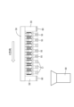
- the surface mounter 10 moves the head unit 50 in the X direction along the dashed line shown in Figure 7, and the recognition camera 90 photographs the chip 17 that is suction-held on each nozzle shaft 55.
- the adsorption state of the chip 17 relative to the nozzle shaft 55 is detected from the image of each chip 17, and the mounting position of the chip 17 relative to the substrate P is corrected based on the detection result, thereby improving the mounting accuracy of the chip 17 relative to the substrate P.
- the surface mounter 10 has two head units 50 on the base 11.
- the two head units 50 are lined up in the X direction (the left-right direction in FIG. 1), and the two head units 50 can be used to mount chips 17 in parallel on two boards P on the transport conveyor 20.
- two traversers 70, shuttles 80, etc. are also installed in the X direction to correspond to the two head units 50.
- FIG. 8 is a block diagram showing the electrical configuration of the surface mounting machine 10.
- the surface mounter 10 includes a controller 100.
- the controller 100 includes a CPU 101 and a memory 103.
- the controller 100 is an example of a control unit.
- a transport program for the substrate P and a chip mounting program are stored in the memory 103.
- the memory 103 also stores data of a reference transfer position of the chip 17 relative to the collet 85.
- the memory 103 also stores data of coordinates (XA, YA) of a movement target point PA when the head unit 50 moves to a mounting work position, and data of coordinates (XB, YB) of a movement target point PB when the head unit 50 moves to a suction work position.
- the controller 100 is electrically connected to the transport conveyor 20, wafer supply section 30, head unit 50, traverser 70, shuttle 80, recognition camera 90, image processing section 95, operation panel 110, etc.
- the controller 100 controls the transport conveyor 20, wafer supply section 30, head unit 50, traverser 70, and shuttle 80.
- the image processing section 95 processes the images captured by the recognition camera 90.
- the operation panel 110 is an interface for operator input.
- the suction nozzle 57 may be tilted with respect to the shaft 56. If a tilted suction nozzle 57 is used, the suction nozzle 57 may pick up a position that is off the chip center CO when the chip 17 is removed from the collet 85, as shown in Fig. 9.
- the chip center CO may be the geometric center of the chip 17 or the center of gravity.
- the controller 100 moves the head unit 50 above the recognition camera 90 and has the recognition camera 90 photograph each suction nozzle 57 from below.
- the controller 100 calculates the amount of deviation ⁇ X1 in the X direction and the amount of deviation ⁇ Y1 in the Y direction of the nozzle center O2 at the tip of the suction nozzle, and sets these as first correction values ⁇ X1, ⁇ Y1.
- the calculated data of the first correction values ⁇ X1, ⁇ Y1 are stored in the memory 103.
- the nozzle center O2 is the center of the nozzle hole (the part that sucks the chip with negative pressure) of the suction nozzle 57.
- the reference for the nozzle center O2 is the center of rotation O1 of the suction nozzle 57.
- Figure 10 is an image of the bottom of the suction nozzle 57, where O1 is the rotation center of the suction nozzle 57, and O2 is the nozzle center of the suction nozzle 57 photographed after nozzle replacement.
- the deviation amounts ⁇ X1 and ⁇ Y1 represent the eccentricity of the nozzle center O2.
- the rotation center O1 of the suction nozzle 57 may be measured using an initial product without eccentricity and the coordinates may be stored in memory 103, or the design value may be stored in memory 103 and used.
- the controller 100 corrects the transfer position of the chip 17 relative to the collet 85 based on the first correction values ⁇ X1 and ⁇ Y1 calculated from the deviation of the suction nozzle 57, and transfers the chip 17 to the corrected transfer position.
- a correction is made to shift the transfer position of the chip 17 relative to the collet 85 by the first correction values ⁇ X1 and ⁇ Y1. Then, the chip 17 is mounted at the corrected transfer position.
- first correction values ⁇ X1, ⁇ Y1 are calculated from the amount of misalignment of the suction nozzle 57 of the first nozzle shaft 55. Then, a correction is made to shift the transfer position of the chip 17 relative to the first collet 85 in the direction of the inclination (misalignment direction) of the first suction nozzle 57 by the calculated first correction values ⁇ X1, ⁇ Y1. Then, the first chip 17 is transferred to the corrected transfer position relative to the first collet 85.
- first correction values ⁇ X1, ⁇ Y1 are calculated from the amount of misalignment of the suction nozzle 57 of the second nozzle shaft 55. Then, a correction is made to shift the transfer position of the chip 17 for the second collet 85 in the direction of the inclination (misalignment direction) of the second suction nozzle 57 by the calculated first correction values ⁇ X1, ⁇ Y1. Then, the second chip 17 is transferred to the corrected transfer position for the second collet 85. Then, a similar correction is made for the other collets 85 to transfer the chip 17.
- the Y-direction correction is performed by adjusting the amount of movement of the traverser body 72 in the Y direction
- the X-direction correction is performed by adjusting the amount of movement of the shuttle body 83 in the X direction.
- the dashed frame 17K shown in Figure 11 indicates the reference transfer position of the chip 17 relative to the collet 85, that is, the transfer position of the chip 17 relative to the collet 85 when there is no misalignment of the suction nozzle 57.
- the data of the reference transfer position is stored in memory 103.
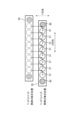
- Figure 12 shows the relationship between the position of each suction nozzle and the chip transfer position.
- the suction nozzle 57 of the second nozzle shaft 55 from the left is tilted, and the position of the nozzle tip is shifted in the Y direction (downward in Figure 12).
- the transfer position of the chip 17 in the second collet 85 is corrected so that the position is shifted in the direction of the nozzle inclination, in this example, in the Y direction (downward in Figure 12). This makes it possible to pick up a position close to the chip center CO regardless of the inclination of the suction nozzle 57.
- FIG. 13 shows the operation flow F1 for correcting the transfer position of the chip 17, and is composed of steps S10 to S50.
- the operation flow F1 is executed, for example, when the surface mounter 10 starts operating.
- operation flow F1 starts with the start of operation, it moves to S10, where the controller 100 determines whether the first correction values ⁇ X1, ⁇ Y1 have been obtained for each nozzle shaft 55 mounted on the head unit 50.
- the first correction values ⁇ X1 and ⁇ Y1 that have already been acquired are stored in memory 103, so whether or not they can be acquired can be determined by referring to memory 103.
- S40 is a process in which the chips 17 supplied from the wafer supply unit 30 are transferred to the collet 85 of the shuttle 80.
- the controller 100 executes S40, it corrects the position of the chip 17 to be transferred to each collet 85 based on the first correction values ⁇ X1, ⁇ Y1. Specifically, it reads out the data of the reference transfer position from the memory 103, and corrects the read out data of the reference transfer position using the first correction values ⁇ X1, ⁇ Y1. Then, it transfers the chip 17 to the corrected transfer position for each collet 85.
- the shuttle 80 moves from the receiving position to the removing position.
- the process proceeds to S20, and the controller 100 uses the recognition camera 90 to capture an image of the suction nozzles 57 of each nozzle shaft 55 mounted on the head unit 50.
- the process proceeds to S30, where the controller 100 calculates the amount of deviation ⁇ X1 in the X direction and the amount of deviation ⁇ Y1 in the Y direction of the nozzle center O2 for each nozzle shaft 55, and sets these as first correction values ⁇ X1 and ⁇ Y1.
- the process thereafter is as described above, and the controller 100 corrects the transfer position of each chip 17 relative to the shuttle 80 based on the first correction values ⁇ X1 and ⁇ Y1 calculated in S30.
- the transfer position of the chip 17 relative to the shuttle 80 is adjusted according to the inclination of the suction nozzle 57 (misalignment of the tip position), so the accuracy of the suction position of the chip 17 by the suction nozzle 57 can be improved.
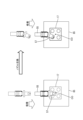
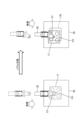
- the head unit 50 may be displaced or tilted in the XY directions due to the influence of distortion caused by thermal expansion of the main axes such as the X-axis and Y-axis that move the head unit 50 in the XY directions.
- the head unit 50 is driven by a linear motor and has an electromagnetic coil 43B. As a result, the head unit 50 itself becomes a heat source, and as shown in FIG. 14, the head unit 50 may be affected by heat in such a way that its position in the planar direction is shifted.
- the head unit 50 affected by heat is displaced from its initial position, which may result in errors in the suction operation position and mounting operation position of the head unit 50.
- the suction operation position is the position where the head unit 50 picks up and removes the chip 17 from the shuttle 80
- the mounting operation position is the position where the head unit 50 mounts the chip 17 removed from the shuttle 80 onto the substrate P.
- the controller 100 moves the head unit 50 to the suction position and simultaneously suctions the chips 17 from each collet 85 of the shuttle 80 using the multiple nozzle shafts 55 (S110 and S120 in FIG. 19).
- the controller 100 moves the head unit 50 so that it passes directly above the recognition camera 90, and captures an image of the two marks 60 on the head unit 50 and the chips 17 held by suction on each nozzle shaft 55 (S130 in FIG. 19).
- the controller 100 then calculates the amount of positional deviation of the head unit 50 from the reference position based on the bottom image of the mark 60.
- the reference position is the position of the head unit 50 when there is no thermal influence, such as in the initial state.
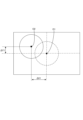
- FIG. 17 is an image of the underside of the mark 60.
- Reference point O3 is the center of the mark when the head unit 50 is photographed by the recognition camera 90 in an initial state or other state where there is no thermal influence
- mark center O4 is the center of the mark when the head unit 50 is photographed by the recognition camera 90 after it has been influenced by heat.
- the amount of deviation ⁇ X2 in the X direction and the amount of deviation ⁇ Y2 in the Y direction from the reference position of the head unit 50 can be calculated by comparing the two mark centers O3 and O4, and these are set as second correction values ⁇ X2 and ⁇ Y2 (S135A in FIG. 19).
- the second correction values ⁇ X2 and ⁇ Y2 are written in memory 103.
- the controller 100 moves the head unit 50 from the suction operation position to the mounting operation position above the substrate to perform the mounting operation, it corrects the coordinates (XA, YA) of the movement target point PA at the mounting operation position using the second correction values ⁇ X2, ⁇ Y2 (S140 in FIG. 19).
- the controller 100 then moves the head unit 50 to the corrected movement target point PA.
- the controller 100 moves the head unit 50 so that the coordinate reference point (e.g., the center) of the head unit 50 coincides with the corrected movement target point PA.
- the initial values of the coordinates (XA, YA) of the movement target point PA are values determined theoretically and from a design perspective, and are stored in the memory 103.
- the coordinates (XA, YA) of the movement target point PA are corrected according to the amount of deviation in the position of the head unit 50, thereby reducing the movement error of the head unit 50 relative to the mounting position, and suppressing deviation in the mounting position of the chip 17 relative to the substrate P (S150 in FIG. 19).
- the controller 100 feeds back the second correction values ⁇ X2, ⁇ Y2 to correct the coordinates (XB, YB) of the movement target point PB at the suction position with the second correction values ⁇ X2, ⁇ Y2 (S135B in FIG. 19).
- the controller 100 then moves the head unit 50 to the corrected movement target point PB. Specifically, the head unit 50 is moved so that the coordinate reference point (e.g., the center) of the head unit 50 coincides with the corrected movement target point PB.
- the initial values of the coordinates (XB, YB) of the movement target point PB are values determined theoretically and designed, and are stored in the memory 103.
- the controller 100 photographs the mark 60 of the head unit 50 before starting operation, and calculates the second correction values ⁇ X2 and ⁇ Y2 based on the obtained image (S100, S105 in FIG. 19). Then, when the head unit 50 moves to the suction operation position, the coordinates (XB, YB) of the movement target point PB are corrected (S120 in FIG. 19).
- the thermal expansion of the head unit 50 can be detected from the recognition result of the distance between the two marks 60, and the detection result of the thermal expansion can be reflected in the correction of the movement target point PA of the component mounting position of the head unit 50 and the correction of the movement target point PB of the suction operation position.
- FIG. 19 is a block diagram showing the pickup position control and mounting position control of the chip 17 by the head unit 50.
- Step S100 shows the mark photographing operation after starting driving.
- Step S110 shows the operation of moving the head unit 50 to the suction operation position.
- Step S120 shows the adsorption operation of the chip 17 by the head unit 50.
- Step S130 shows the mark photographing operation after the chip is attracted.
- Step S140 shows the operation of moving the head unit 50 to the mounting operation position.
- Step S150 shows the operation of mounting the chip 17 by the head unit 50.
- S105 shows the correction of the moving target point of the suction work position using the second correction value calculated from the mark photographing result of S110.
- S135B shows the correction of the moving target point of the suction work position using the second correction value calculated from the mark photographing result of S130.
- S135A shows the correction of the moving target point of the mounting work position using the second correction value calculated from the mark photographing result of S130.
- the correction of the moving target point of the suction operation position of the head unit 50 and the correction of the moving target point of the mounting operation position disclosed in embodiment 2 can be performed in parallel with the correction of the transfer position of the chip 17 disclosed in embodiment 1.
- the transfer position correction of the chip 17 disclosed in the first embodiment can be omitted, and the movement target point correction of the suction operation position of the head unit 50 disclosed in the second embodiment and the movement target point correction of the mounting operation position can be performed separately.
- the error in the pickup position and the mounting position of the head unit 50 can be reduced, so the pickup position accuracy and the mounting position accuracy of the chip 17 can be improved.
- the surface mounter 10 of embodiment 3 obtains data on the pitch PH between the shafts 56 from inspection data at the time of product shipment, etc., and stores the data in advance in the memory 103.
- the positions of the traverser 70 and the shuttle 80 are adjusted to correct the transfer position of the chip 17 relative to each collet 85 of the shuttle 80.
- the suction nozzle 57 can pick up the chip at a position close to the chip center CO, improving the suction accuracy of the chip 17.
- the present invention is not limited to flip chip bonders, but can be widely applied to any device that mounts chips on a substrate.
- the electronic components mounted on the substrate are not limited to bare chips cut from a semiconductor wafer, and can be widely applied to cases where other electronic components such as molded components or ceramic components are mounted.
- a head unit having multiple nozzle shafts is given as an example of the second head.
- the second head only needs to be able to pick up and remove components from the shuttle and mount them on the substrate, and may have, for example, a single nozzle shaft.
- the shuttle 80 that moves back and forth in the X direction is given as an example of the relay stage.
- the relay stage does not necessarily need to be movable and may be fixed as long as it can relay parts at least between the first head and the second head.
- a traverser 70 that moves back and forth in the Y direction is given as an example of the first head.
- the first head is not limited to a traverser as long as it can transfer a component to the relay stage.
- the first head may be configured to be movable in two directions, X and Y, and the second head alone may be configured to adjust the position of the component in the X and Y directions relative to the relay stage.
- the marks 60 are provided on both sides of the head unit 50, but at least one mark 60 is sufficient. Also, the mark 60 may be attached anywhere on the head unit 50 as long as the position can be recognized by the recognition camera 90.
- the head unit 50 is linearly driven, but a ball screw or the like may also be used.
Landscapes
- Engineering & Computer Science (AREA)
- Manufacturing & Machinery (AREA)
- Microelectronics & Electronic Packaging (AREA)
- Operations Research (AREA)
- Supply And Installment Of Electrical Components (AREA)
- Container, Conveyance, Adherence, Positioning, Of Wafer (AREA)
Priority Applications (3)
| Application Number | Priority Date | Filing Date | Title |
|---|---|---|---|
| JP2025512367A JPWO2024209674A1 (cg-RX-API-DMAC7.html) | 2023-04-07 | 2023-04-07 | |
| PCT/JP2023/014352 WO2024209674A1 (ja) | 2023-04-07 | 2023-04-07 | 表面実装機 |
| TW113107684A TWI911660B (zh) | 2023-04-07 | 2024-03-04 | 表面安裝機 |
Applications Claiming Priority (1)
| Application Number | Priority Date | Filing Date | Title |
|---|---|---|---|
| PCT/JP2023/014352 WO2024209674A1 (ja) | 2023-04-07 | 2023-04-07 | 表面実装機 |
Publications (1)
| Publication Number | Publication Date |
|---|---|
| WO2024209674A1 true WO2024209674A1 (ja) | 2024-10-10 |
Family
ID=92971569
Family Applications (1)
| Application Number | Title | Priority Date | Filing Date |
|---|---|---|---|
| PCT/JP2023/014352 Ceased WO2024209674A1 (ja) | 2023-04-07 | 2023-04-07 | 表面実装機 |
Country Status (3)
| Country | Link |
|---|---|
| JP (1) | JPWO2024209674A1 (cg-RX-API-DMAC7.html) |
| TW (1) | TWI911660B (cg-RX-API-DMAC7.html) |
| WO (1) | WO2024209674A1 (cg-RX-API-DMAC7.html) |
Citations (7)
| Publication number | Priority date | Publication date | Assignee | Title |
|---|---|---|---|---|
| JP2001251098A (ja) * | 2000-03-07 | 2001-09-14 | Yamaha Motor Co Ltd | 部品の実装位置補正方法および表面実装機 |
| JP3234021B2 (ja) * | 1993-02-05 | 2001-12-04 | 山形カシオ株式会社 | 電子部品ピックアップ装置 |
| JP2002026592A (ja) * | 2000-07-11 | 2002-01-25 | Matsushita Electric Ind Co Ltd | 電子部品の実装装置および実装方法 |
| JP2003101294A (ja) * | 2001-09-20 | 2003-04-04 | Fuji Mach Mfg Co Ltd | 電気部品供給方法および電気部品装着システム |
| JP2003168894A (ja) * | 2001-11-30 | 2003-06-13 | Yamaha Motor Co Ltd | 表面実装機 |
| JP2009194306A (ja) * | 2008-02-18 | 2009-08-27 | Juki Corp | 部品供給装置 |
| JP2014203916A (ja) * | 2013-04-03 | 2014-10-27 | ヤマハ発動機株式会社 | 部品実装装置 |
Family Cites Families (7)
| Publication number | Priority date | Publication date | Assignee | Title |
|---|---|---|---|---|
| JP3196626B2 (ja) * | 1995-12-26 | 2001-08-06 | ソニー株式会社 | 部品実装方法 |
| JP4167790B2 (ja) * | 2000-03-10 | 2008-10-22 | 東レエンジニアリング株式会社 | チップ実装装置 |
| CN100377326C (zh) * | 2002-12-02 | 2008-03-26 | 松下电器产业株式会社 | 零件供给头装置、零件供给装置、零件安装装置、以及安装头部的移动方法 |
| CN107079619B (zh) * | 2014-08-13 | 2020-07-17 | 株式会社新川 | 安装装置与测量方法 |
| CN114786461B (zh) * | 2017-11-21 | 2024-11-05 | 哈里斯股份有限公司 | 电子元器件安装装置及电子装置的制造方法 |
| JP7368962B2 (ja) * | 2019-07-09 | 2023-10-25 | 芝浦メカトロニクス株式会社 | 実装装置 |
| CN115148617B (zh) * | 2021-03-31 | 2026-05-29 | 芝浦机械电子装置株式会社 | 电子零件安装装置 |
-
2023
- 2023-04-07 JP JP2025512367A patent/JPWO2024209674A1/ja active Pending
- 2023-04-07 WO PCT/JP2023/014352 patent/WO2024209674A1/ja not_active Ceased
-
2024
- 2024-03-04 TW TW113107684A patent/TWI911660B/zh active
Patent Citations (7)
| Publication number | Priority date | Publication date | Assignee | Title |
|---|---|---|---|---|
| JP3234021B2 (ja) * | 1993-02-05 | 2001-12-04 | 山形カシオ株式会社 | 電子部品ピックアップ装置 |
| JP2001251098A (ja) * | 2000-03-07 | 2001-09-14 | Yamaha Motor Co Ltd | 部品の実装位置補正方法および表面実装機 |
| JP2002026592A (ja) * | 2000-07-11 | 2002-01-25 | Matsushita Electric Ind Co Ltd | 電子部品の実装装置および実装方法 |
| JP2003101294A (ja) * | 2001-09-20 | 2003-04-04 | Fuji Mach Mfg Co Ltd | 電気部品供給方法および電気部品装着システム |
| JP2003168894A (ja) * | 2001-11-30 | 2003-06-13 | Yamaha Motor Co Ltd | 表面実装機 |
| JP2009194306A (ja) * | 2008-02-18 | 2009-08-27 | Juki Corp | 部品供給装置 |
| JP2014203916A (ja) * | 2013-04-03 | 2014-10-27 | ヤマハ発動機株式会社 | 部品実装装置 |
Also Published As
| Publication number | Publication date |
|---|---|
| JPWO2024209674A1 (cg-RX-API-DMAC7.html) | 2024-10-10 |
| TW202442062A (zh) | 2024-10-16 |
| TWI911660B (zh) | 2026-01-11 |
Similar Documents
| Publication | Publication Date | Title |
|---|---|---|
| JP6928134B2 (ja) | 電子部品の実装装置と実装方法、およびパッケージ部品の製造方法 | |
| JP4896757B2 (ja) | 表面実装機 | |
| CN118213297A (zh) | 电子零件的安装装置 | |
| JP2017183378A (ja) | 電子部品の実装装置 | |
| JP2009016673A (ja) | 部品の吸着位置補正方法および部品移載装置 | |
| JP2009010167A (ja) | 部品移載装置 | |
| CN113451175B (zh) | 电子零件的安装装置 | |
| JP2000117592A (ja) | 部品搭載装置及び部品供給装置 | |
| JP3709800B2 (ja) | 実装機およびその部品装着方法 | |
| JP5297913B2 (ja) | 実装機 | |
| JP2003243899A (ja) | 実装機、実装方法 | |
| TWI911660B (zh) | 表面安裝機 | |
| US11116121B2 (en) | Mounting target working device | |
| US6315185B2 (en) | Ball mount apparatus | |
| CN113871319B (zh) | 安装装置及安装方法 | |
| JP6666692B2 (ja) | 部品実装機、部品吸着方法 | |
| JP2003243898A (ja) | 実装機、実装方法 | |
| CN117337620B (zh) | 元件移载装置 | |
| JPH11274240A (ja) | 電子部品の実装装置および実装方法 | |
| JP2007214494A (ja) | マーク認識方法および表面実装機 | |
| JP2000312100A (ja) | 表面実装機の部品認識装置 | |
| JP7811728B2 (ja) | 部品装着装置及び部品装着方法 | |
| JP2006310647A (ja) | 表面実装機および部品実装方法 | |
| JP7522231B2 (ja) | 部品実装装置および部品実装方法 | |
| JP4243745B2 (ja) | ヘッドとワークの位置決め装置及び位置決め方法 |
Legal Events
| Date | Code | Title | Description |
|---|---|---|---|
| 121 | Ep: the epo has been informed by wipo that ep was designated in this application |
Ref document number: 23932085 Country of ref document: EP Kind code of ref document: A1 |
|
| ENP | Entry into the national phase |
Ref document number: 2025512367 Country of ref document: JP Kind code of ref document: A |
|
| WWE | Wipo information: entry into national phase |
Ref document number: 2025512367 Country of ref document: JP |
|
| NENP | Non-entry into the national phase |
Ref country code: DE |
|
| 122 | Ep: pct application non-entry in european phase |
Ref document number: 23932085 Country of ref document: EP Kind code of ref document: A1 |