WO2024204065A1 - 光学積層体、表示装置、センサー - Google Patents
光学積層体、表示装置、センサー Download PDFInfo
- Publication number
- WO2024204065A1 WO2024204065A1 PCT/JP2024/011704 JP2024011704W WO2024204065A1 WO 2024204065 A1 WO2024204065 A1 WO 2024204065A1 JP 2024011704 W JP2024011704 W JP 2024011704W WO 2024204065 A1 WO2024204065 A1 WO 2024204065A1
- Authority
- WO
- WIPO (PCT)
- Prior art keywords
- liquid crystal
- crystal layer
- optical axis
- light
- optical laminate
- Prior art date
- Legal status (The legal status is an assumption and is not a legal conclusion. Google has not performed a legal analysis and makes no representation as to the accuracy of the status listed.)
- Ceased
Links
Images







Classifications
-
- G—PHYSICS
- G02—OPTICS
- G02F—OPTICAL DEVICES OR ARRANGEMENTS FOR THE CONTROL OF LIGHT BY MODIFICATION OF THE OPTICAL PROPERTIES OF THE MEDIA OF THE ELEMENTS INVOLVED THEREIN; NON-LINEAR OPTICS; FREQUENCY-CHANGING OF LIGHT; OPTICAL LOGIC ELEMENTS; OPTICAL ANALOGUE/DIGITAL CONVERTERS
- G02F1/00—Devices or arrangements for the control of the intensity, colour, phase, polarisation or direction of light arriving from an independent light source, e.g. switching, gating or modulating; Non-linear optics
- G02F1/01—Devices or arrangements for the control of the intensity, colour, phase, polarisation or direction of light arriving from an independent light source, e.g. switching, gating or modulating; Non-linear optics for the control of the intensity, phase, polarisation or colour
- G02F1/13—Devices or arrangements for the control of the intensity, colour, phase, polarisation or direction of light arriving from an independent light source, e.g. switching, gating or modulating; Non-linear optics for the control of the intensity, phase, polarisation or colour based on liquid crystals, e.g. single liquid crystal display cells
- G02F1/133—Constructional arrangements; Operation of liquid crystal cells; Circuit arrangements
- G02F1/1333—Constructional arrangements; Manufacturing methods
- G02F1/1347—Arrangement of liquid crystal layers or cells in which the final condition of one light beam is achieved by the addition of the effects of two or more layers or cells
-
- G—PHYSICS
- G02—OPTICS
- G02B—OPTICAL ELEMENTS, SYSTEMS OR APPARATUS
- G02B5/00—Optical elements other than lenses
- G02B5/18—Diffraction gratings
-
- G—PHYSICS
- G02—OPTICS
- G02B—OPTICAL ELEMENTS, SYSTEMS OR APPARATUS
- G02B5/00—Optical elements other than lenses
- G02B5/30—Polarising elements
-
- G—PHYSICS
- G02—OPTICS
- G02B—OPTICAL ELEMENTS, SYSTEMS OR APPARATUS
- G02B5/00—Optical elements other than lenses
- G02B5/32—Holograms used as optical elements
-
- G—PHYSICS
- G02—OPTICS
- G02F—OPTICAL DEVICES OR ARRANGEMENTS FOR THE CONTROL OF LIGHT BY MODIFICATION OF THE OPTICAL PROPERTIES OF THE MEDIA OF THE ELEMENTS INVOLVED THEREIN; NON-LINEAR OPTICS; FREQUENCY-CHANGING OF LIGHT; OPTICAL LOGIC ELEMENTS; OPTICAL ANALOGUE/DIGITAL CONVERTERS
- G02F1/00—Devices or arrangements for the control of the intensity, colour, phase, polarisation or direction of light arriving from an independent light source, e.g. switching, gating or modulating; Non-linear optics
- G02F1/01—Devices or arrangements for the control of the intensity, colour, phase, polarisation or direction of light arriving from an independent light source, e.g. switching, gating or modulating; Non-linear optics for the control of the intensity, phase, polarisation or colour
- G02F1/13—Devices or arrangements for the control of the intensity, colour, phase, polarisation or direction of light arriving from an independent light source, e.g. switching, gating or modulating; Non-linear optics for the control of the intensity, phase, polarisation or colour based on liquid crystals, e.g. single liquid crystal display cells
- G02F1/133—Constructional arrangements; Operation of liquid crystal cells; Circuit arrangements
- G02F1/1333—Constructional arrangements; Manufacturing methods
- G02F1/1335—Structural association of cells with optical devices, e.g. polarisers or reflectors
- G02F1/13363—Birefringent elements, e.g. for optical compensation
-
- G—PHYSICS
- G02—OPTICS
- G02F—OPTICAL DEVICES OR ARRANGEMENTS FOR THE CONTROL OF LIGHT BY MODIFICATION OF THE OPTICAL PROPERTIES OF THE MEDIA OF THE ELEMENTS INVOLVED THEREIN; NON-LINEAR OPTICS; FREQUENCY-CHANGING OF LIGHT; OPTICAL LOGIC ELEMENTS; OPTICAL ANALOGUE/DIGITAL CONVERTERS
- G02F1/00—Devices or arrangements for the control of the intensity, colour, phase, polarisation or direction of light arriving from an independent light source, e.g. switching, gating or modulating; Non-linear optics
- G02F1/01—Devices or arrangements for the control of the intensity, colour, phase, polarisation or direction of light arriving from an independent light source, e.g. switching, gating or modulating; Non-linear optics for the control of the intensity, phase, polarisation or colour
- G02F1/13—Devices or arrangements for the control of the intensity, colour, phase, polarisation or direction of light arriving from an independent light source, e.g. switching, gating or modulating; Non-linear optics for the control of the intensity, phase, polarisation or colour based on liquid crystals, e.g. single liquid crystal display cells
- G02F1/133—Constructional arrangements; Operation of liquid crystal cells; Circuit arrangements
- G02F1/1333—Constructional arrangements; Manufacturing methods
- G02F1/1337—Surface-induced orientation of the liquid crystal molecules, e.g. by alignment layers
Definitions
- the present invention relates to an optical laminate, a display device, and a sensor.
- Optical elements that control the direction of light are used in many optical devices or systems.
- optical elements that control the direction of light are used in various optical devices, such as backlights for liquid crystal display devices, head mounted displays (HMDs) such as AR (Augmented Reality) glasses that overlay virtual images and various information on the scene that is actually being viewed, projectors, beam steering, and sensors for detecting objects and measuring the distance to objects.
- HMDs head mounted displays
- AR Augmented Reality
- Patent Document 1 discloses a liquid crystal diffraction element including a first cholesteric liquid crystal layer formed by cholesterically aligning a liquid crystal compound, and a second cholesteric liquid crystal layer laminated to the first cholesteric liquid crystal layer.
- the two cholesteric liquid crystal layers are laminated via an adhesive layer.
- the first cholesteric liquid crystal layer and the second cholesteric liquid crystal layer have different periods of liquid crystal orientation patterns.
- an object of the present invention is to provide an optical laminate that includes a plurality of liquid crystal layers in which the orientation states of liquid crystal compounds are different from each other, and that has a low reflectance of the regular reflection component when light is incident.
- Another object of the present invention is to provide a display device and a sensor.
- a first liquid crystal layer including a liquid crystal compound a first liquid crystal layer including a liquid crystal compound; a second liquid crystal layer including a liquid crystal compound; The first liquid crystal layer and the second liquid crystal layer are adjacent to each other, the first liquid crystal layer has a liquid crystal alignment pattern in which the direction of an optical axis derived from a liquid crystal compound changes while continuously rotating along at least one direction in the plane;
- each of the first liquid crystal layer and the second liquid crystal layer has a plurality of pairs of bright and dark lines along one direction, the pairs being derived from the direction of the optical axis, in a cross-sectional image obtained by observing a cross-section cut in a thickness direction along one direction with a scanning electron microscope;
- the second liquid crystal layer is a cholesteric liquid crystal layer;
- an optical laminate which includes a plurality of liquid crystal layers in which the liquid crystal compound has a different orientation state from one another and which has a low reflectance of the regular reflection component when light is incident thereon.
- a display device and a sensor can be provided.
- FIG. 1 is a side view conceptually showing an example of a first embodiment of the optical laminate of the present invention.
- FIG. 2 is a diagram for explaining the liquid crystal alignment pattern of the first liquid crystal layer.
- FIG. 3 is a diagram for explaining the liquid crystal alignment pattern of the second liquid crystal layer.
- FIG. 4 is a diagram for explaining the function of the first liquid crystal layer.
- FIG. 5 is a diagram for explaining the functions of an example of the first embodiment of the optical laminate.
- FIG. 6 is a side view conceptually showing another example of the first embodiment of the optical laminate of the present invention.
- FIG. 7 is a diagram for explaining the functions of another example of the first embodiment of the optical laminate.
- FIG. 8 is a side view conceptually showing an example of the second embodiment of the optical laminate of the present invention.
- FIG. 1 is a side view conceptually showing an example of a first embodiment of the optical laminate of the present invention.
- FIG. 2 is a diagram for explaining the liquid crystal alignment pattern of the first liquid crystal layer.
- FIG. 9 is a diagram for explaining the liquid crystal alignment pattern of the first liquid crystal layer.
- FIG. 10 is a diagram for explaining the function of the first liquid crystal layer.
- FIG. 11 is a diagram for explaining the function of the first liquid crystal layer.
- FIG. 12 is a diagram for explaining the liquid crystal alignment pattern of the second liquid crystal layer.
- FIG. 13 is a diagram for explaining functions of an example of the second embodiment of the optical laminate.
- FIG. 14 is a side view conceptually showing an example of the third embodiment of the optical laminate of the present invention.
- FIG. 15 is a diagram for explaining the functions of an example of the third embodiment of the optical laminate of the present invention.
- FIG. 16 is a side view conceptually showing another example of the third embodiment of the optical laminate of the present invention.
- FIG. 17 is a diagram for explaining the functions of another example of the third embodiment of the optical laminate of the present invention.
- FIG. 18 is a conceptual diagram of an example of an exposure apparatus for exposing an alignment film.
- a numerical range expressed using “to” means a range that includes the numerical values before and after “to” as the lower and upper limits.
- each component may be used alone or in combination of two or more substances corresponding to each component.
- the content of the component refers to the total content of the substances used in combination, unless otherwise specified.
- (meth)acrylate is used to mean “either one or both of acrylate and methacrylate.”
- visible light refers to electromagnetic waves having wavelengths visible to the human eye, in the wavelength range of 380 to 780 nm, while non-visible light refers to light having wavelengths shorter than 380 nm and longer than 780 nm.
- light in the wavelength region of 420 to 490 nm is blue light
- light in the wavelength region of 495 to 570 nm is green light
- light in the wavelength region of 620 to 750 nm is red light.
- a characteristic feature of the optical laminate of the present invention is that two liquid crystal layers having different orientation states of the liquid crystal compounds are arranged adjacent to each other.
- the two liquid crystal layers are laminated via an adhesive layer or the like.
- the liquid crystal layer and the adhesive layer have different refractive indices, and the presence of such an adhesive layer makes it easy for reflection to occur at the interface between the liquid crystal layer and the adhesive layer, resulting in an increase in the regular reflection component.
- the two liquid crystal layers are arranged adjacent to each other, making the above problem less likely to occur.
- Fig. 1 is a side view conceptually showing an example of a first embodiment of the optical laminate of the present invention.
- the first embodiment corresponds to an embodiment in which the first liquid crystal layer and the second liquid crystal layer are both cholesteric liquid crystal layers.
- the example shown in Fig. 1 corresponds to an embodiment that satisfies the following requirement 1.
- the second liquid crystal layer has a liquid crystal alignment pattern in which the direction of the optical axis derived from the liquid crystal compound changes while continuously rotating along at least one direction in the plane, The rotation direction of the optical axis in the liquid crystal alignment pattern of the first liquid crystal layer is opposite to the rotation direction of the optical axis in the liquid crystal alignment pattern of the second liquid crystal layer.
- the optical laminate 10A includes a first liquid crystal layer 12A, which is a cholesteric liquid crystal layer, and a second liquid crystal layer 14A, which is a cholesteric liquid crystal layer.
- the first liquid crystal layer 12A and the second liquid crystal layer 14A are disposed adjacent to each other.
- the first liquid crystal layer 12A and the second liquid crystal layer 14A correspond to layers in which a cholesteric liquid crystal phase is fixed.
- the first liquid crystal layer 12A and the second liquid crystal layer 14A are both layers in which a liquid crystal compound having a cholesteric orientation is fixed.
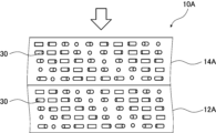
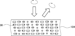
- Fig. 2 shows a plan view of the first liquid crystal layer 12A in the optical laminate 10A shown in Fig. 1.
- Fig. 2 in order to clearly show the configuration of the first liquid crystal layer 12A, only the liquid crystal compound 30 located on the surface of the first liquid crystal layer 12A on the second liquid crystal layer 14A side is shown.
- Fig. 3 shows a plan view of the second liquid crystal layer 14A in the optical laminate 10A shown in Fig. 1.
- the plan view is a view of the second liquid crystal layer 14A from above (the direction of the outline arrow) in Fig. 1, that is, Fig.
- Fig. 3 in order to clearly show the configuration of the second liquid crystal layer 14A, only the liquid crystal compound 30 located on the surface of the second liquid crystal layer 14A on the first liquid crystal layer 12A side is shown.
- the first liquid crystal layer 12A has a helical structure in which the liquid crystal compound 30 is stacked while rotating along a helical axis along the thickness direction, and although it is shown in a simplified form in FIG. 1, the liquid crystal compound 30 is stacked in a helical shape by one rotation (360° rotation) as one helical pitch, and the helically rotating liquid crystal compound 30 has a structure in which multiple pitches are stacked. In this respect, the same is true for the second liquid crystal layer 14A.
- cholesteric liquid crystal phases exhibit selective reflectivity at specific wavelengths.
- the helical pitch P is one pitch (helical period) of the helical structure of the cholesteric liquid crystal phase.
- the helical pitch P is one turn of the helix, that is, the length of the helical axis direction in which the director of the liquid crystal compound constituting the cholesteric liquid crystal phase rotates 360°. If the liquid crystal compound is a rod-shaped liquid crystal, the director is the long axis direction.
- the helical pitch of the cholesteric liquid crystal phase depends on the type of chiral agent used together with the liquid crystal compound when forming the cholesteric liquid crystal layer, or on the concentration of the chiral agent added, and the desired pitch can be obtained by adjusting these.
- the adjustment of the pitch is described in detail in Fujifilm Research Report No. 50 (2005), pp. 60-63.
- the sense of helix and the pitch can be measured by the methods described in "Introduction to Liquid Crystal Chemistry Experiments” edited by the Japanese Liquid Crystal Society, published by Sigma Publishing in 2007, p. 46, and "Liquid Crystal Handbook” edited by the Liquid Crystal Handbook Editorial Committee, published by Maruzen, p. 196.
- the selective reflection central wavelength (for example, the selective reflection central wavelength of a reflective layer or a cholesteric liquid crystal layer) refers to the average value of two wavelengths that exhibit a half-value transmittance, T1/2 (%), expressed by the following formula, when the minimum transmittance value of the target object (component) is Tmin (%).
- T1/2 100 - (100 - Tmin) ⁇ 2
- Cholesteric liquid crystal phases exhibit selective reflection for either left-handed or right-handed circularly polarized light at a specific wavelength. Whether the reflected light is right-handed or left-handed circularly polarized light depends on the helical twist direction (sense) of the cholesteric liquid crystal phase. When the helical twist direction of the cholesteric liquid crystal phase is right-handed, right-handed circularly polarized light is reflected, and when the helical twist direction is left-handed, left-handed circularly polarized light is reflected.
- the direction of rotation of the cholesteric liquid crystal phase can be adjusted by the type of liquid crystal compound forming the cholesteric liquid crystal layer and/or the type of chiral agent added.
- the half width of the reflection wavelength band is adjusted depending on the application of the optical laminate, and is preferably from 10 to 500 nm, more preferably from 20 to 300 nm, and even more preferably from 30 to 150 nm.
- the first liquid crystal layer 12A and the second liquid crystal layer 14A each have a liquid crystal alignment pattern in which the direction of the optical axis 30A derived from the liquid crystal compound 30 changes while continuously rotating in one direction indicated by the arrow X.
- the direction of the optical axis 30A derived from the liquid crystal compound 30 changes while continuously rotating clockwise in one direction indicated by the arrow X
- the direction of the optical axis 30A derived from the liquid crystal compound 30 changes while continuously rotating counterclockwise in one direction indicated by the arrow X.
- the rotation direction of the optical axis 30A derived from the liquid crystal compound 30 in the liquid crystal alignment pattern of the first liquid crystal layer 12A is opposite to the rotation direction of the optical axis 30A derived from the liquid crystal compound 30 in the liquid crystal alignment pattern of the second liquid crystal layer 14A.
- the optical axis 30A derived from the liquid crystal compound 30 is an axis along which the refractive index is highest in the liquid crystal compound 30.
- the liquid crystal compound 30 is a rod-shaped liquid crystal compound
- the optical axis 30A is aligned along the long axis direction of the rod shape.
- the optical axis 30A originating from the liquid crystal compound 30 will also be referred to as the "optical axis 30A of the liquid crystal compound 30" or the “optical axis 30A.”
- the liquid crystal compound 30 In the first liquid crystal layer 12A, the liquid crystal compound 30 is two-dimensionally aligned in a plane parallel to the direction of the arrow X and the direction Y perpendicular to the direction of the arrow X.
- the liquid crystal compound 30 is two-dimensionally aligned in a plane parallel to the direction of the arrow X and the direction Y perpendicular to the direction of the arrow X.
- the first liquid crystal layer 12A has a liquid crystal orientation pattern in which the direction of the optical axis 30A derived from the liquid crystal compound 30 changes while continuously rotating along the direction of the arrow X within the plane of the first liquid crystal layer 12A.
- the direction of the optical axis 30A of the liquid crystal compound 30 changes while continuously rotating in the direction of the arrow X (a predetermined direction), specifically means that the angle formed between the optical axis 30A of the liquid crystal compound 30 aligned along the direction of the arrow X and the direction of the arrow X differs depending on the position in the direction of the arrow X, and the angle formed between the optical axis 30A and the direction of the arrow X changes sequentially from ⁇ to ⁇ +180° or ⁇ 180° along the direction of the arrow X.
- the difference in angle between the optical axes 30A of the liquid crystal compounds 30 adjacent to each other in the direction of the arrow X is preferably 45° or less, more preferably 15° or less, and even more
- the liquid crystal compounds 30 forming the first liquid crystal layer 12A are arranged at equal intervals in the Y direction perpendicular to the direction of the arrow X, i.e., in the Y direction perpendicular to the direction in which the optical axis 30A continuously rotates.
- the angles between the optical axes 30A of the liquid crystal compounds 30 aligned in the Y direction and the arrow X direction are equal to each other.
- the length (distance) over which the optical axis 30A of the liquid crystal compound 30 rotates 180° in the direction of the arrow X in which the orientation of the optical axis 30A continuously rotates and changes in the plane in the liquid crystal orientation pattern of the liquid crystal compound 30 is defined as the length ⁇ of one period in the liquid crystal orientation pattern.
- the length of one period in the liquid crystal orientation pattern is defined as the distance from when the angle between the optical axis 30A of the liquid crystal compound 30 and the direction of the arrow X changes from ⁇ to ⁇ +180°.
- the distance between the centers in the direction of the arrow X of two liquid crystal compounds 30 that are at the same angle with respect to the direction of the arrow X is defined as the length ⁇ of one period.
- the distance between the centers in the direction of the arrow X of two liquid crystal compounds 30 whose directions of the arrow X and the optical axis 30A coincide with each other is defined as the length ⁇ of one period.
- this length ⁇ of one period is also referred to as "one period ⁇ ".
- the liquid crystal alignment pattern of the first liquid crystal layer 12A repeats this one period ⁇ in the direction of the arrow X, that is, in one direction in which the orientation of the optical axis 30A changes by continuously rotating.
- Figure 3 conceptually shows a plan view of the second liquid crystal layer 14A, but since it has the same configuration as the first liquid crystal layer 12A, except that the rotation direction of the optical axis 30A derived from the liquid crystal compound 30 in the liquid crystal orientation pattern of the second liquid crystal layer 14A is opposite to the rotation direction of the optical axis 30A derived from the liquid crystal compound 30 in the liquid crystal orientation pattern of the first liquid crystal layer 12A, a description thereof will be omitted. That is, one period ⁇ of the liquid crystal orientation pattern of the first liquid crystal layer 12A is the same as one period ⁇ of the liquid crystal orientation pattern of the second liquid crystal layer 14A.
- the helical pitch P of the helical structure of the first liquid crystal layer 12A is the same as the helical pitch P of the helical structure of the second liquid crystal layer 14A.
- a cholesteric liquid crystal layer formed by fixing a cholesteric liquid crystal phase usually specularly reflects incident light (circularly polarized light).
- the first liquid crystal layer 12A having the above-mentioned liquid crystal orientation pattern reflects the incident light in a direction angled in the X direction with respect to the specular reflection.
- the first liquid crystal layer 12A reflects light incident from the normal direction (right-handed circularly polarized light in Fig. 4) not in the normal direction but at an angle with respect to the normal direction.
- the light incident from the normal direction is, in other words, light incident from the front, perpendicular to the main surface.
- the main surface is the largest surface of the sheet-like material.
- the reflection angle of light by the first liquid crystal layer 12A, in which the optical axis 30A of the liquid crystal compound 30 rotates continuously in one direction (X direction), varies depending on the wavelength of the reflected light. Specifically, the longer the wavelength of light, the larger the angle of the reflected light with respect to the incident light.
- the reflection angle of light by the first liquid crystal layer 12A in which the optical axis 30A of the liquid crystal compound 30 rotates continuously in one direction (X direction) varies depending on the length ⁇ of one period of the liquid crystal orientation pattern in which the optical axis 30A rotates 180° in the X direction, i.e., one period ⁇ . Specifically, the shorter the one period ⁇ , the larger the angle of the reflected light with respect to the incident light.
- the period ⁇ is not particularly limited and may be appropriately set depending on the application of the optical laminate 10A, and is preferably 50 ⁇ m or less, more preferably 10 ⁇ m or less. In consideration of the accuracy of the liquid crystal alignment pattern, it is preferably 0.1 ⁇ m or more.
- the second liquid crystal layer 14A also has a liquid crystal alignment pattern in which the optical axis 30A changes while continuously rotating in the X direction (one predetermined direction) within the plane. Therefore, the second liquid crystal layer 14A reflects the incident light in a direction angled with respect to the X-direction with respect to the specular reflection. However, the second liquid crystal layer 14A reflects left-handed circularly polarized light not in the normal direction but at an angle with respect to the normal direction.
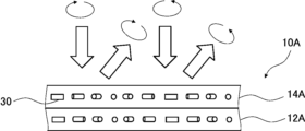
- FIG. 5 a case will be described in which right-handed circularly polarized light and left-handed circularly polarized light are incident on the optical laminate 10A from the normal direction.
- the configurations of the first liquid crystal layer 12A and the second liquid crystal layer 14A are shown in a simplified manner.
- right-handed circularly polarized light is incident on the optical laminate 10A, it is reflected in a direction having a predetermined angle in the X direction by the action of the first liquid crystal layer 12A, as shown in Fig. 4.
- left-handed circularly polarized light is incident on the optical laminate 10A, it is reflected in a direction having a predetermined angle in the X direction by the action of the second liquid crystal layer 14A.
- both right-handed and left-handed circularly polarized light can be reflected in the same angular direction, i.e., the optical laminate 10A can diffract different circularly polarized light at the same angle.
- the first liquid crystal layer 12A and the second liquid crystal layer 14A are disposed adjacent to each other, so that the reflectance of the regular reflection component is low.
- one period ⁇ of the liquid crystal alignment pattern of the first liquid crystal layer 12A is the same as one period ⁇ of the liquid crystal alignment pattern of the second liquid crystal layer 14A, but the present invention is not limited to this embodiment.
- one period ⁇ of the liquid crystal alignment pattern of the first liquid crystal layer may be different from one period ⁇ of the liquid crystal alignment pattern of the second liquid crystal layer.
- the reflection angle of the reflected light can be adjusted.
- the length of one period ⁇ in the liquid crystal alignment pattern of the first liquid crystal layer may be gradually changed along the X direction (one direction).
- the length of one period ⁇ in the liquid crystal alignment pattern of the first liquid crystal layer may be gradually shortened or lengthened along the X direction (one direction).
- the length of one period ⁇ in the liquid crystal alignment pattern of the second liquid crystal layer may be gradually changed along the X direction (one direction).
- the length of one period ⁇ in the liquid crystal alignment pattern of the second liquid crystal layer may be gradually shortened or lengthened along the X direction (one direction).
- the helical pitch P of the helical structure of the first liquid crystal layer 12A is the same as the helical pitch P of the helical structure of the second liquid crystal layer 14A, but the present invention is not limited to this embodiment.
- the helical pitch P of the helical structure of the first liquid crystal layer may be different from the helical pitch P of the helical structure of the second liquid crystal layer.
- the pitch P of the spiral By adjusting the pitch P of the spiral, the wavelength of the reflected light can be adjusted.
- the helical pitch P of the helical structure of the first liquid crystal layer may be gradually changed along the thickness direction.
- the helical pitch P of the helical structure of the first liquid crystal layer may be gradually increased or decreased along the thickness direction.
- the helical pitch P of the helical structure of the second liquid crystal layer may be gradually changed along the thickness direction.
- the helical pitch P of the helical structure of the second liquid crystal layer may be gradually increased or decreased along the thickness direction.
- the rotation direction of the helical structure of the first liquid crystal layer 12A and the rotation direction of the helical structure of the second liquid crystal layer 14A are opposite, but the present invention is not limited to this embodiment.
- the rotation direction of the helical structure of the first liquid crystal layer and the rotation direction of the helical structure of the second liquid crystal layer may be the same.
- the rotation direction of the optical axis 30A originating from the liquid crystal compound 30 in the liquid crystal orientation pattern of the first liquid crystal layer 12A is opposite to the rotation direction of the optical axis 30A originating from the liquid crystal compound 30 in the liquid crystal orientation pattern of the second liquid crystal layer 14A, but the present invention is not limited to this embodiment.
- the rotation direction of the optical axis originating from the liquid crystal compound in the liquid crystal orientation pattern of the first liquid crystal layer may be the same as the rotation direction of the optical axis originating from the liquid crystal compound in the liquid crystal orientation pattern of the second liquid crystal layer.
- Fig. 6 is a side view conceptually showing another example of the first embodiment of the optical laminate of the present invention. As described later, the example shown in Fig. 6 corresponds to an embodiment that satisfies the following requirement 2.
- the second liquid crystal layer has a liquid crystal alignment pattern in which the direction of the optical axis derived from the liquid crystal compound changes while continuously rotating along at least one direction in the plane,
- the length over which the orientation of the optical axis derived from the liquid crystal compound in the liquid crystal orientation pattern of the first liquid crystal layer rotates 180° in-plane is different from the length over which the orientation of the optical axis derived from the liquid crystal compound in the liquid crystal orientation pattern of the second liquid crystal layer rotates 180° in-plane.
- the optical laminate 10B includes a first liquid crystal layer 12B which is a cholesteric liquid crystal layer, and a second liquid crystal layer 14B which is a cholesteric liquid crystal layer.
- the first liquid crystal layer 12B and the second liquid crystal layer 14B are disposed adjacent to each other.
- the first liquid crystal layer 12B and the second liquid crystal layer 14B correspond to layers in which a cholesteric liquid crystal phase is fixed.
- Both the first liquid crystal layer 12B and the second liquid crystal layer 14B have a spiral structure in which the liquid crystal layers are stacked and rotated along a spiral axis along the thickness direction, similar to the first liquid crystal layer 12A and the second liquid crystal layer 14A, and have the liquid crystal orientation pattern described above.
- the rotation direction of the optical axis originating from the liquid crystal compound in the liquid crystal alignment pattern of the first liquid crystal layer 12B is the same as the rotation direction of the optical axis originating from the liquid crystal compound in the liquid crystal alignment pattern of the second liquid crystal layer 14B.
- the rotation direction of the helical structure of the first liquid crystal layer 12B is the same as the rotation direction of the helical structure of the second liquid crystal layer 14B.
- the helical pitch P of the helical structure of the first liquid crystal layer 12B is different from the helical pitch P of the helical structure of the second liquid crystal layer 14B, and the helical pitch P of the helical structure of the first liquid crystal layer 12B is larger.
- the length of one period ⁇ 1 in the liquid crystal orientation pattern of the first liquid crystal layer 12B is longer than the length of one period ⁇ 2 in the liquid crystal orientation pattern of the second liquid crystal layer 14B.
- Both the first liquid crystal layer 12B and the second liquid crystal layer 14B reflect circularly polarized light with the same rotation direction, and the wavelength of the light reflected by the first liquid crystal layer 12B is longer than the wavelength of the light reflected by the second liquid crystal layer 14B.
- ⁇ Second embodiment> 8 is a side view conceptually illustrating an example of the second embodiment of the optical laminate of the present invention.
- the second embodiment corresponds to an embodiment in which the liquid crystal compound in both the first liquid crystal layer and the second liquid crystal layer is not twisted along the thickness direction, or the rotation angle of the optical axis derived from the liquid crystal compound in the thickness direction is less than 360°.
- the example shown in FIG. 8 corresponds to an aspect that satisfies the following requirement 1.
- the second liquid crystal layer has a liquid crystal alignment pattern in which the direction of the optical axis derived from the liquid crystal compound changes while continuously rotating along at least one direction in the plane,
- the rotation direction of the optical axis in the liquid crystal alignment pattern of the first liquid crystal layer is opposite to the rotation direction of the optical axis in the liquid crystal alignment pattern of the second liquid crystal layer.
- the optical laminate 10C includes a first liquid crystal layer 12C and a second liquid crystal layer 14C.
- the first liquid crystal layer 12C and the second liquid crystal layer 14C are disposed adjacent to each other.
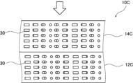
- Fig. 9 shows a plan view of the first liquid crystal layer 12C in the optical laminate 10C shown in Fig. 8.
- Fig. 9 shows a plan view of the first liquid crystal layer 12C in the optical laminate 10C shown in Fig. 8.
- the first liquid crystal layer 12C and the second liquid crystal layer 14C are both formed using a liquid crystal composition containing a liquid crystal compound.
- the liquid crystal compound is fixed.
- the first liquid crystal layer 12C has a liquid crystal alignment pattern in which the direction of the optical axis 30A derived from the liquid crystal compound 30 changes while continuously rotating clockwise in one direction indicated by the arrow X within the plane of the first liquid crystal layer 12C.
- the optical axis 30A derived from the liquid crystal compound 30 is an axis along which the refractive index is highest in the liquid crystal compound 30.
- the length (distance) over which the optical axis 30A of the liquid crystal compound 30 rotates 180° in the direction of the arrow X in which the orientation of the optical axis 30A continuously rotates and changes in the plane is defined as the length ⁇ of one period of the liquid crystal orientation pattern.
- the length of one period of the liquid crystal orientation pattern is defined as the distance from when the angle between the optical axis 30A of the liquid crystal compound 30 and the direction of the arrow X changes from ⁇ to ⁇ +180°.
- the distance between the centers in the direction of the arrow X of two liquid crystal compounds 30 that are at the same angle with respect to the direction of the arrow X is defined as the length ⁇ of one period.
- the distance between the centers in the direction of the arrow X of two liquid crystal compounds 30 whose directions of the arrow X and the optical axis 30A coincide with each other is defined as the length ⁇ of one period.
- this length ⁇ of one period is also referred to as "one period ⁇ ".
- the liquid crystal alignment pattern of the first liquid crystal layer 12C repeats this one period ⁇ in the direction of the arrow X, that is, in one direction in which the orientation of the optical axis 30A changes by continuously rotating.
- the liquid crystal compounds 30 aligned in the Y direction have the same angle between their optical axes 30A and the direction of the arrow X (one direction in which the orientation of the optical axes of the liquid crystal compounds 30 rotates).
- a region in which the liquid crystal compounds 30 aligned in the Y direction and having the same angle between their optical axes 30A and the direction of the arrow X is defined as a region R.
- the value of the in-plane retardation (Re) in each region R is preferably a half wavelength, i.e., ⁇ /2.
- the refractive index difference associated with the refractive index anisotropy of the region R in the first liquid crystal layer 12C is a refractive index difference defined by the difference between the refractive index in the direction of the slow axis in the plane of the region R and the refractive index in the direction perpendicular to the direction of the slow axis.
- the refractive index difference ⁇ n associated with the refractive index anisotropy of the region R is equal to the difference between the refractive index of the liquid crystal compound 30 in the direction of the optical axis 30A and the refractive index of the liquid crystal compound 30 in the direction perpendicular to the optical axis 30A in the plane of the region R. That is, the refractive index difference ⁇ n is equal to the refractive index difference of the liquid crystal compound.
- Fig. 10 When circularly polarized light is incident on the first liquid crystal layer 12C, the light is refracted and the direction of the circularly polarized light is changed.
- This effect is conceptually shown in Fig. 10 by taking the first liquid crystal layer 12C as an example. It is assumed that the product of the refractive index difference of the liquid crystal compound and the thickness of the first liquid crystal layer 12C is ⁇ /2. In Fig. 10, the number of liquid crystal compounds 30 in the first liquid crystal layer 12C is reduced in order to simplify the drawing. As shown in FIG.
- the direction of the optical axis 30A changes while rotating along the direction of the arrow X, so the amount of change in the absolute phase of the incident light L1 differs according to the direction of the optical axis 30A.
- the liquid crystal orientation pattern formed in the first liquid crystal layer 12C is a periodic pattern in the direction of the arrow X
- the incident light L1 that passes through the first liquid crystal layer 12C is given a periodic absolute phase Q1 in the direction of the arrow X corresponding to the direction of each optical axis 30A, as shown in FIG. 10.
- an equiphase surface E1 inclined in the opposite direction to the direction of the arrow X is formed.
- the transmitted light L2 is refracted so as to be tilted toward a direction perpendicular to the equiphase surface E1, and travels in a direction different from that of the incident light L1 .
- the left-handed circularly polarized incident light L1 is converted into the right-handed circularly polarized transmitted light L2 that is tilted at a certain angle in the direction of the arrow X with respect to the incident direction.
- the amount of change in the absolute phase of the incident light L4 differs according to the direction of the optical axis 30A. Furthermore, since the liquid crystal orientation pattern formed in the first liquid crystal layer 12C is a periodic pattern in the direction of the arrow X, the incident light L4 that passes through the first liquid crystal layer 12C is given a periodic absolute phase Q2 in the direction of the arrow X corresponding to the direction of each optical axis 30A, as shown in FIG.
- the incident light L4 is right-handed circularly polarized light
- the periodic absolute phase Q2 in the direction of the arrow X corresponding to the direction of the optical axis 30A is opposite to that of the incident light L1 which is left-handed circularly polarized light.
- the incident light L4 forms an equiphase surface E2 which is inclined in the direction of the arrow X opposite to that of the incident light L1 . Therefore, the incident light L4 is refracted so as to be tilted toward a direction perpendicular to the equiphase surface E2, and travels in a direction different from the traveling direction of the incident light L4 . In this way, the incident light L4 is converted into left-handed circularly polarized transmitted light L5 that is tilted at a certain angle in the direction opposite to the direction of the arrow X with respect to the incident direction.
- FIG. 13 a case will be described in which left-handed circularly polarized light is incident on the optical laminate 10C from the normal direction. Note that in FIG. 13, the configurations of the first liquid crystal layer 12C and the second liquid crystal layer 14C are shown in a simplified manner. When left-handed circularly polarized light is incident on the optical laminate 10C, first, right-handed circularly polarized light is incident in a direction tilted at a certain angle due to the action of the second liquid crystal layer 14C, as shown in Fig. 13.
- one period ⁇ of the liquid crystal orientation pattern of the first liquid crystal layer 12C is the same as one period ⁇ of the liquid crystal orientation pattern of the second liquid crystal layer 14C, but the present invention is not limited to this embodiment.
- one period ⁇ of the liquid crystal orientation pattern of the first liquid crystal layer may be different from one period ⁇ of the liquid crystal orientation pattern of the second liquid crystal layer.
- the above-mentioned requirement 2 may be satisfied.
- the length of one period ⁇ in the liquid crystal alignment pattern of the first liquid crystal layer may be gradually changed along the X direction (one direction).
- the length of one period ⁇ in the liquid crystal alignment pattern of the first liquid crystal layer may be gradually shortened or lengthened along the X direction (one direction).
- the length of one period ⁇ in the liquid crystal alignment pattern of the second liquid crystal layer may be gradually changed along the X direction (one direction).
- the length of one period ⁇ in the liquid crystal alignment pattern of the second liquid crystal layer may be gradually shortened or lengthened along the X direction (one direction).
- the period ⁇ is not particularly limited and may be appropriately set depending on the application of the optical laminate 10C, and is preferably 50 ⁇ m or less, more preferably 10 ⁇ m or less. In consideration of the accuracy of the liquid crystal alignment pattern, it is preferably 0.1 ⁇ m or more.
- the liquid crystal compound 30 in the first liquid crystal layer 12C and the liquid crystal compound in the second liquid crystal layer 14C are aligned in the same direction in the thickness direction, but the present invention is not limited to this embodiment.
- the liquid crystal compound in the first liquid crystal layer in the first liquid crystal layer, the liquid crystal compound may be twisted along the thickness direction, and for example, the rotation angle of the optical axis derived from the liquid crystal compound in the thickness direction of the first liquid crystal layer may be less than 360°.
- the liquid crystal compound in the second liquid crystal layer, may be twisted along the thickness direction, and for example, the rotation angle of the optical axis derived from the liquid crystal compound in the thickness direction of the second liquid crystal layer may be less than 360°.
- the twist angle is 360° or more, and the liquid crystal layer has selective reflectivity for reflecting specific circularly polarized light in a specific wavelength range.
- the "twisted alignment" does not include cholesteric alignment, and selective reflectivity does not occur in a liquid crystal layer having a twisted alignment.
- the twist angle of the liquid crystal compound 30 in the thickness direction is preferably about 10 to 200°, and more preferably about 45 to 180°.
- ⁇ Third embodiment> 14 is a side view conceptually illustrating an example of the third embodiment of the optical laminate of the present invention. As described later, the third embodiment corresponds to an embodiment that satisfies requirement 3.
- Requirement 3 The liquid crystal compound in the second liquid crystal layer is aligned in one direction on the surface facing the first liquid crystal layer.
- the ⁇ /4 plate is a plate that has a function of converting linearly polarized light of a certain wavelength into circularly polarized light (or circularly polarized light into linearly polarized light), more specifically, a plate that exhibits an in-plane retardation Re of ⁇ /4 (or an odd multiple thereof) at a certain wavelength ⁇ nm.
- the in-plane retardation (Re(550)) of the ⁇ /4 plate at a wavelength of 550 nm may have an error of about 25 nm around the ideal value (137.5 nm), and is preferably 110 to 160 nm, and more preferably 120 to 150 nm, for example.
- the emitted right-handed circularly polarized light is again incident on the second liquid crystal layer 14D and is emitted as linearly polarized light.
- linearly polarized light can be diffracted with high diffraction efficiency.
- the first liquid crystal layer 12A and the second liquid crystal layer 14D are disposed adjacent to each other, so that the reflectance of the regular reflection component is low.
- the second liquid crystal layer 14D may be a ⁇ /2 plate.
- a ⁇ /2 plate is an optically anisotropic film in which the in-plane retardation Re( ⁇ ) at a specific wavelength ⁇ nm satisfies Re( ⁇ ) ⁇ /2. This formula may be achieved at any wavelength in the visible light range (e.g., 550 nm).
- the in-plane retardation Re(550) at a wavelength of 550 nm satisfies the following relationship: 210nm ⁇ Re(550) ⁇ 300nm
- the second liquid crystal layer may be a cholesteric liquid crystal layer.
- the configuration of the first liquid crystal layer 12A included in the optical laminate 10D is not limited to the configuration in FIG. 14. As described above, one period ⁇ of the liquid crystal orientation pattern, the helical pitch P of the helical structure, the rotation direction of the helical structure, and the rotation direction of the optical axis derived from the liquid crystal compound in the liquid crystal orientation pattern can be adjusted as appropriate.
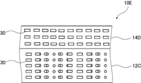
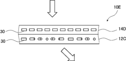
- FIG. 16 is a side view conceptually showing another example of the third embodiment of the optical laminate of the present invention.
- the optical laminate 10E includes a first liquid crystal layer 12C and a second liquid crystal layer 14D.
- the first liquid crystal layer 12C and the second liquid crystal layer 14D are disposed adjacent to each other.
- the first liquid crystal layer 12C included in the optical laminate 10E has a configuration similar to that of the first liquid crystal layer 12C shown in FIG.
- the second liquid crystal layer 14D included in the optical laminate 10E has a configuration similar to that of the second liquid crystal layer 14D shown in FIG.
- the optical laminate 10E linearly polarized light can be diffracted with high diffraction efficiency.
- the first liquid crystal layer 12C and the second liquid crystal layer 14D are disposed adjacent to each other, so that the reflectance of the regular reflection component is low.
- the second liquid crystal layer 14D a layer functioning as a ⁇ /4 plate is used as the second liquid crystal layer 14D, but the present invention is not limited to this embodiment.
- the second liquid crystal layer may be a ⁇ /2 plate and a cholesteric liquid crystal layer.
- the configuration of the first liquid crystal layer 12C included in the optical laminate 10E is not limited to the configuration shown in FIG. 16. As described above, one period ⁇ of the liquid crystal orientation pattern and the rotation direction of the optical axis derived from the liquid crystal compound in the liquid crystal orientation pattern can be adjusted as appropriate.
- the optical laminates 10A to 10E each satisfy one of the requirements 1 to 3. Whether or not requirements 1 to 3 are satisfied can be confirmed by observing a cross section of the optical laminate with a scanning electron microscope. Regarding requirement 1, it can be confirmed whether the requirement is satisfied by irradiating light to the optical laminate and evaluating its optical properties. For example, in the case of a configuration such as the optical laminate 10A described above, when right-handed circularly polarized light and left-handed circularly polarized light are incident on the optical laminate, the right-handed circularly polarized light and left-handed circularly polarized light are reflected in the same direction, so it can be confirmed whether the optical laminate 10A is configured by evaluating its optical properties. In addition, for example, when circularly polarized light is incident on the optical laminate, if the diffraction angle is larger than the angle estimated from the in-plane pattern period of the observed cross section, it can be confirmed whether the optical laminate 10C is configured.
- the average thickness of each of the first liquid crystal layer and the second liquid crystal layer contained in the optical laminate described above is not particularly limited, and an optimal thickness is selected depending on various applications.
- the average thickness is preferably 0.05 to 50 ⁇ m, more preferably 0.1 to 40 ⁇ m, even more preferably 0.2 to 30 ⁇ m, and particularly preferably 0.3 to 15 ⁇ m.
- the average thickness of the first and second liquid crystal layers may vary depending on the application.
- the average thickness of the first liquid crystal layer and the second liquid crystal layer is preferably 0.05 to 15 ⁇ m, more preferably 0.1 to 10 ⁇ m, even more preferably 0.2 to 8 ⁇ m, and particularly preferably 0.3 to 5 ⁇ m.
- the average thickness of the first liquid crystal layer and the second liquid crystal layer is preferably 0.2 to 50 ⁇ m, more preferably 0.5 to 40 ⁇ m, even more preferably 1 to 30 ⁇ m, and particularly preferably 3 to 15 ⁇ m.
- the average thickness of the first liquid crystal layer is obtained by measuring the thickness of the first liquid crystal layer at 10 points and calculating the arithmetic average.
- the average thickness of the second liquid crystal layer is obtained by measuring the thickness of the second liquid crystal layer at 10 points and calculating the arithmetic average.
- the above-mentioned optical laminate may include other members in addition to the first liquid crystal layer and the second liquid crystal layer.
- the optical stack may include a support.
- a support various types of sheet-like materials (films, plates) can be used as long as they can support the first and second liquid crystal layers.
- the support preferably has a transmittance to the corresponding light of 50% or more, more preferably 70% or more, and even more preferably 85% or more.
- the thickness of the support is preferably from 1 to 1000 ⁇ m, more preferably from 3 to 250 ⁇ m, and even more preferably from 5 to 150 ⁇ m.
- the support may be a single layer or a multilayer.
- Examples of the support in the case of a single layer include supports made of glass, triacetyl cellulose, polyethylene terephthalate, polycarbonate, polyvinyl chloride, poly(meth)acrylate, polyolefin, etc.
- Examples of the support in the case of a multilayer include those that include any of the above-mentioned single-layer supports as a substrate and have another layer provided on the surface of this substrate.
- the optical laminate may include an alignment film.
- the first and second liquid crystal layers are preferably formed on an alignment film, which may be used as an alignment film for forming the above-mentioned liquid crystal alignment pattern.
- a so-called photo-alignment film formed by irradiating a photo-alignable material with polarized or non-polarized light to form an alignment film is preferably used. That is, in the optical laminate, a photo-alignment film formed by applying a photo-alignment material onto a support is preferably used as the alignment film.
- the photo-alignment film can be irradiated with polarized light from a vertical direction or an oblique direction, while the photo-alignment film can be irradiated with unpolarized light from an oblique direction.
- photo-alignment materials used in the photo-alignment film examples include those described in JP-A-2006-285197, JP-A-2007-076839, JP-A-2007-138138, JP-A-2007-094071, JP-A-2007-121721, JP-A-2007-140465, JP-A-2007-156439, and JP-A-2007-21721.
- photocrosslinkable polyimides photocrosslinkable polyamides and photocrosslinkable polyesters described in JP-T-2003-520878, JP-T-2004-529220 and JP-T-4162850, and photodimerizable compounds described in JP-A-9-118717, JP-T-10-506420, JP-T-2003-505561, WO 2010/150748, JP-A-2013-177561 and JP-A-2014-12823, in particular cinnamate compounds, chalcone compounds and coumarin compounds, are exemplified as preferred examples.
- azo compounds photocrosslinkable polyimides, photocrosslinkable polyamides, photocrosslinkable polyesters, cinnamate compounds, and chalcone compounds are preferably used.
- the thickness of the alignment film is preferably from 0.01 to 5 ⁇ m, and more preferably from 0.05 to 2 ⁇ m.
- FIG. 18 conceptually shows an example of an exposure apparatus for forming an alignment pattern by exposing an alignment film.
- 18 includes a light source 64 equipped with a laser 62, a ⁇ /2 plate 65 for changing the polarization direction of laser light M emitted by the laser 62, a polarizing beam splitter 68 for splitting the laser light M emitted by the laser 62 into two beams MA and MB, mirrors 70A and 70B arranged on the optical paths of the two split beams MA and MB, and ⁇ /4 plates 72A and 72B.
- the light source 64 emits linearly polarized light P 0.
- the ⁇ /4 plate 72A converts the linearly polarized light P 0 (beam MA) into right-handed circularly polarized light P R
- the ⁇ /4 plate 72B converts the linearly polarized light P 0 (beam MB) into left-handed circularly polarized light P L.
- the ⁇ /4 plates 72A and 72B used here may be any ⁇ /4 plate that corresponds to the wavelength of the light to be irradiated. Since the exposure device 60 irradiates laser light M, for example, if the central wavelength of the laser light M is 325 nm, a ⁇ /4 plate that functions with light of a wavelength of 325 nm may be used.
- a support 82 having an alignment film 80 before an alignment pattern is formed is placed in an exposure section, and two light beams MA and MB are caused to intersect and interfere on the alignment film 80, and the alignment film 80 is exposed by being irradiated with the interference light. Due to the interference at this time, the polarization state of the light irradiated to the alignment film 80 changes periodically in the form of interference fringes, thereby obtaining an alignment pattern in the alignment film 80 in which the alignment state changes periodically.
- the period of the orientation pattern can be adjusted by changing the crossing angle ⁇ of the two light beams MA and MB.
- the method for producing the optical laminate is not particularly limited, and any known method can be used. Among these, a method using a photoalignment polymer having a repeating unit containing a photoalignment group and a repeating unit containing a cleavage group that decomposes to produce a polar group by the action of at least one selected from the group consisting of light, heat, acid, and base (hereinafter also referred to as "cleavage-group-containing photoalignment polymer”) is preferred. More specifically, a method for producing an optical laminate including the following steps 1 to 4 is preferred.
- Step 1 A step of forming a coating film using a composition for forming a first liquid crystal layer, which contains a liquid crystal compound, a cleavable group-containing photoalignable polymer, and a photoacid generator.
- Step 2 A step of orienting the liquid crystal compound in the coating film obtained in step 1, and carrying out a curing treatment and an acid generating treatment to form a first liquid crystal layer.
- Step 3 A step of subjecting the first liquid crystal layer obtained in step 2 to a photoalignment treatment.
- Step 4 A step of applying a composition for forming a second liquid crystal layer, which contains a liquid crystal compound, onto the first liquid crystal layer obtained in step 3 to form a second liquid crystal layer.
- liquid crystal compound either a low molecular weight liquid crystal compound or a polymeric liquid crystal compound can be used.
- low molecular weight liquid crystal compound refers to a liquid crystal compound that does not have a repeating unit in its chemical structure.
- polymeric liquid crystal compound refers to a liquid crystal compound that has a repeating unit in its chemical structure.
- the low molecular weight liquid crystal compound include the liquid crystal compounds described in JP-A-2013-228706.
- the polymer liquid crystal compound include thermotropic liquid crystal polymers described in JP 2011-237513 A and WO 2019/131943 A.
- the polymer liquid crystal compound may have a crosslinkable group (e.g., an acryloyl group or a methacryloyl group) at the end.
- the liquid crystal compounds may be used alone or in combination of two or more.
- the cleavable group-containing photoalignable polymer has a repeating unit containing a photoalignable group and a repeating unit containing a cleavable group that decomposes by the action of at least one selected from the group consisting of light, heat, acid, and base to generate a polar group.
- repeating unit A An example of a repeating unit containing a photoalignable group that the cleavable group-containing photoalignable polymer has is the repeating unit represented by the following formula (A) (hereinafter also abbreviated as "repeating unit A").
- R 1 represents a hydrogen atom or a substituent
- L 1 represents a divalent linking group
- A represents a photoalignable group
- the substituent represented by one embodiment of R 1 is preferably a halogen atom, a linear alkyl group having 1 to 20 carbon atoms, a branched or cyclic alkyl group having 3 to 20 carbon atoms, a linear halogenated alkyl group having 1 to 20 carbon atoms, an alkoxy group having 1 to 20 carbon atoms, an aryl group having 6 to 20 carbon atoms, an aryloxy group having 6 to 20 carbon atoms, a cyano group, or an amino group.
- Examples of the substituent that the alkylene group, arylene group and imino group may have include a halogen atom, an alkyl group, an alkoxy group, an aryl group, an aryloxy group, a cyano group, a carboxy group, an alkoxycarbonyl group and a hydroxyl group.
- Examples of halogen atoms include a fluorine atom, a chlorine atom, a bromine atom, and an iodine atom, and among these, a fluorine atom or a chlorine atom is preferable.
- the alkyl group preferably has 1 to 18 carbon atoms
- the alkoxy group preferably has 1 to 18 carbon atoms
- the aryl group preferably has 6 to 12 carbon atoms.
- *1 represents the bonding position of the carbon atom bonded to R 1 in the above formula (A)
- *2 represents the bonding position of A in the above formula (A).
- a divalent linking group represented by any of the above formulas (4), (5), (9) and (10) is preferred because it provides a good balance between solubility in a solvent and the solvent resistance of the resulting liquid crystal layer.
- specific examples of the group that isomerizes by the action of light preferably include groups having a skeleton of at least one compound selected from the group consisting of an azobenzene compound, a stilbene compound, a spiropyran compound, a cinnamic acid compound, and a hydrazono- ⁇ -keto ester compound.
- the group has a skeleton of at least one derivative or compound selected from the group consisting of cinnamic acid derivatives, coumarin derivatives, chalcone derivatives, maleimide derivatives, azobenzene compounds, stilbene compounds, and spiropyran compounds, and among these, it is more preferable that the group has a skeleton of a cinnamic acid derivative or an azobenzene compound, and even more preferable that the group has a skeleton of a cinnamic acid derivative, because the alignment of the liquid crystal compound described above is good.
- the photo-aligning group is preferably a photo-aligning group described in paragraphs [0036] to [0040] of WO 2020/179864.
- Examples of the repeating unit A represented by the above formula (A) include the repeating units described in paragraphs [0041] to [0049] of WO 2020/179864.
- the content of the repeating units containing photoalignable groups in the photoalignable polymer is not particularly limited, and is preferably 3 to 40 mol %, more preferably 6 to 30 mol %, and even more preferably 10 to 25 mol %, based on the total repeating units of the photoalignable polymer.
- cleavable group examples include cleavable groups (bonds) represented by any of the following formulas (rk-1) to (rk-13).
- R each independently represents a hydrogen atom or a monovalent organic group.
- R examples of the monovalent organic group represented by R include linear or cyclic alkyl groups having 1 to 20 carbon atoms, and aryl groups having 6 to 20 carbon atoms which may have a substituent.
- the anion portion in the above formulae (rk-10) and (rk-11) is not particularly limited since it does not affect the cleavage, and either an inorganic anion or an organic anion can be used.
- inorganic anions include halide ions such as chloride ion and bromide ion; sulfonate anion; and the like.
- organic anion include carboxylate anions such as acetate anion; and organic sulfonate anions such as methanesulfonate anion and paratoluenesulfonate anion; and the like.
- repeating units examples include the repeating units described in paragraphs [0037] and [0038] of WO 2018/216812. Moreover, such a repeating unit is preferably a repeating unit containing a cleavable group that generates a polar group by the action of an acid, and the following specific examples are preferable.
- the content of repeating units containing cleavable groups in the photoalignment polymer is not particularly limited, and is preferably 5 mol% or more, more preferably 10 mol% or more, even more preferably 15 mol% or more, more preferably 70 mol% or less, even more preferably 50 mol% or less, and particularly preferably 40 mol% or less, based on the total repeating units of the photoalignment polymer.
- the photoalignable polymer may have repeating units other than the repeating units described above.
- monomers that form other repeating units include acrylic acid ester compounds, methacrylic acid ester compounds, maleimide compounds, acrylamide compounds, acrylonitrile, maleic anhydride, styrene compounds, and vinyl compounds.
- the method for synthesizing the photoalignment polymer is not particularly limited, and for example, the photoalignment polymer can be synthesized by mixing a monomer that forms a repeating unit containing the above-mentioned photoreactive group, a monomer that forms a repeating unit containing the above-mentioned cleavable group, and a monomer that forms any other repeating unit, and polymerizing the mixture in an organic solvent using a radical polymerization initiator.
- the weight average molecular weight (Mw) of the photoalignable polymer is not particularly limited, and is preferably from 10,000 to 500,000, more preferably from 10,000 to 300,000, and even more preferably from 30,000 to 150,000.
- the weight average molecular weight in the present invention is a value measured by gel permeation chromatography (GPC) under the following conditions.
- the content of the photoalignable polymer in the composition for forming the first liquid crystal layer is preferably 0.1 to 20 mass % relative to the content of the liquid crystal compound, and more preferably 0.5 to 10 mass %.
- the composition for forming the first liquid crystal layer contains a photoacid generator.
- the photoacid generator is not particularly limited, and is preferably a compound that responds to actinic rays having a wavelength of 300 nm or more, preferably 300 to 450 nm, and generates an acid.
- the photoacid generator can be preferably used in combination with a sensitizer, so long as it responds to actinic rays having a wavelength of 300 nm or more and generates an acid when used in combination with a sensitizer.
- the composition for forming the first liquid crystal layer preferably contains a polymerization initiator.
- the polymerization initiator is not particularly limited, and examples thereof include a thermal polymerization initiator and a photopolymerization initiator depending on the type of polymerization reaction.
- the polymerization initiator is preferably a photopolymerization initiator capable of initiating a polymerization reaction by irradiation with ultraviolet light.
- the content of the photopolymerization initiator in the composition for forming the first liquid crystal layer is preferably 0.1 to 20% by mass, more preferably 0.5 to 10% by mass, based on the content of the liquid crystal compound.
- the first liquid crystal layer forming composition may contain a chiral agent.
- the first liquid crystal layer forming composition contains a chiral agent, the first liquid crystal layer becomes a cholesteric liquid crystal layer.
- Chiral agents have the function of inducing a helical structure in the cholesteric liquid crystal phase. Chiral agents can be selected according to the purpose, since the twist direction or helical pitch of the helix induced varies depending on the compound.
- the chiral agent is not particularly limited, and known compounds (for example, those described in Liquid Crystal Device Handbook, Chapter 3, Section 4-3, Chiral Agents for TN (twisted nematic) and STN (Super Twisted Nematic), p.
- a polymerizable chiral agent and a polymerizable liquid crystal compound can be polymerized to form a polymer having a repeating unit derived from the polymerizable liquid crystal compound and a repeating unit derived from the chiral agent.
- the content of the chiral dopant in the composition for forming the first liquid crystal layer is preferably from 0.01 to 200 mol %, more preferably from 1 to 30 mol %, based on the molar amount of the liquid crystal compound contained.
- the method for forming a coating film of the composition for forming the first liquid crystal layer is not particularly limited, and an example of the method is to apply the composition for forming the first liquid crystal layer onto a support and, if necessary, perform a drying process.
- the support may be any of the supports described above.
- An alignment film may be disposed on the support. Examples of the alignment film include the alignment films described above.
- the method for applying the composition for forming the first liquid crystal layer is not particularly limited, and examples include spin coating, air knife coating, curtain coating, roller coating, wire bar coating, gravure coating, and die coating.
- Step 2 the liquid crystal compound in the coating film obtained in step 1 is aligned, and a curing process and an acid generating process are carried out to form a first liquid crystal layer.
- the cleavable group-containing photoalignable polymer is likely to be unevenly distributed on the air-side surface of the coating film. In particular, when the cleavable group-containing photoalignable polymer has a fluorine atom or a silicon atom, the uneven distribution is likely to occur.
- the method for orienting the liquid crystal compound in the coating film is not particularly limited, and examples include a method of heating the coating film.
- the curing treatment may be a light irradiation treatment or a heat treatment.
- the conditions for the curing treatment are not particularly limited, but in the polymerization by light irradiation, it is preferable to use ultraviolet rays.
- the irradiation amount is preferably 10 mJ/cm 2 to 50 J/cm 2 , and more preferably 20 mJ/cm 2 to 5 J/cm 2.
- the curing treatment may be performed under heating conditions.
- the treatment for generating an acid from a photoacid generator in a coating film is a treatment for generating an acid by irradiating the photoacid generator with light to which the photoacid generator is sensitive. By carrying out this treatment, cleavage at the cleavable group proceeds, and a group containing a fluorine atom or a silicon atom is eliminated.
- the light irradiation treatment carried out in the above treatment may be any treatment to which the photoacid generator is photosensitive, and may be, for example, a method of irradiating ultraviolet light.
- a lamp that emits ultraviolet light such as a high-pressure mercury lamp or a metal halide lamp, may be used.
- the irradiation dose is preferably 10 mJ/cm 2 to 50 J/cm 2 , and more preferably 20 mJ/cm 2 to 5 J/cm 2 .
- Step 3 is a step of performing a photo-alignment treatment on the first liquid crystal layer obtained in step 2.
- an alignment regulating force can be imparted to the surface of the first liquid crystal layer.
- This photo-alignment treatment can form a first liquid crystal layer having an alignment regulating force capable of forming the above-mentioned liquid crystal alignment pattern.
- an alignment regulating force capable of forming various alignment patterns can be imparted.
- the wavelength of the polarized or unpolarized light is not particularly limited as long as it is light to which the photo-alignable group is sensitive.
- Examples include ultraviolet light, near ultraviolet light, and visible light, with near ultraviolet light of 250 to 450 nm being preferred.
- Examples of light sources for irradiating polarized or non-polarized light include xenon lamps, high-pressure mercury lamps, extra-high-pressure mercury lamps, and metal halide lamps.
- an interference filter or a color filter on the ultraviolet or visible light obtained from such light sources, the wavelength range of the light to be irradiated can be limited.
- a polarizing filter or a polarizing prism on the light from these light sources, linearly polarized light can be obtained.
- the integrated amount of polarized or unpolarized light is not particularly limited, but is preferably 1 to 500 mJ/cm 2 , and more preferably 5 to 400 mJ/cm 2 .
- the illuminance of the polarized or unpolarized light is not particularly limited, but is preferably 0.1 to 500 mW/cm 2 , and more preferably 1 to 300 mW/cm 2 .
- Step 4 is a step of forming a second liquid crystal layer by applying a composition for forming a second liquid crystal layer containing a liquid crystal compound onto the first liquid crystal layer obtained in step 3.
- a composition for forming a second liquid crystal layer containing a liquid crystal compound onto the first liquid crystal layer obtained in step 3.
- an optical laminate including the first liquid crystal layer and the second liquid crystal layer arranged adjacent to each other is obtained.
- the liquid crystal compound contained in the composition for forming the second liquid crystal layer include the liquid crystal compound contained in the composition for forming the first liquid crystal layer.
- components other than the liquid crystal compound contained in the second liquid crystal layer forming composition include the components contained in the first liquid crystal layer forming composition.
- An example of a method for applying the second liquid crystal layer forming composition is a method for applying the first liquid crystal layer forming composition.
- a method for forming the second liquid crystal layer from a coating film obtained by applying the composition for forming a second liquid crystal layer the method for forming the first liquid crystal layer can be mentioned.
- the optical laminate of the present invention can be used for various purposes, such as display devices, sensors, and optical polarizing elements.
- Display devices include augmented reality and virtual reality display devices.
- Example 1 (Formation of alignment film) The following coating solution for forming an alignment film was continuously applied onto the support using a wire bar of #2. The support on which the coating film of the coating solution for forming an alignment film was formed was dried on a hot plate at 60° C. for 60 seconds to form an alignment film.
- the alignment film was exposed using the exposure apparatus shown in FIG. 18 to form a patterned alignment film P-1 having an alignment pattern.
- a laser emitting laser light with a wavelength (325 nm) was used.
- the exposure dose by the interference light was set to 300 mJ/ cm2 .
- the period ⁇ was 2.0 ⁇ m.
- the above-mentioned composition X for forming the first liquid crystal layer was applied onto the above-mentioned alignment film using a wire bar coater #7, heated at 60° C. for 2 minutes, and irradiated with ultraviolet light at an irradiation dose of 100 mJ/cm 2 using a UV-LED (wavelength 365 nm) while maintaining the temperature at 60° C. and purging with nitrogen so that the atmosphere had an oxygen concentration of 1.0% by volume or less. After further heating at 130° C. for 1 minute, the obtained liquid crystal layer was exposed to interference light from an exposure device shown in FIG. 18 to form a first liquid crystal layer A having a photoalignment function.
- a wire bar coater #7 heated at 60° C. for 2 minutes, and irradiated with ultraviolet light at an irradiation dose of 100 mJ/cm 2 using a UV-LED (wavelength 365 nm) while maintaining the temperature at 60° C. and purging with nitrogen so that the atmosphere had an oxygen concentration of
- a laser emitting laser light with a wavelength (325 nm) was used.
- the exposure dose by the interference light was set to 300 mJ/ cm2 .
- the period ⁇ of the orientation pattern formed by the two laser lights and the interference was controlled by changing the crossing angle (crossing angle ⁇ ) of the two lights.
- the optical axes of the ⁇ /4 plates 72A and 72B in the exposure device were rotated by 90°, respectively, to adjust the rotation direction of the optical axis.
- the thickness of the first liquid crystal layer A was 3.0 ⁇ m, and one period ⁇ was 2.0 ⁇ m.
- Horizontal alignment agent In the formula below, the numerical value for each repeating unit indicates the content (mass%) of each repeating unit relative to the total repeating units.
- Cleavage group-containing photoalignable polymer (FP-1) (The numerical value for each repeating unit indicates the content (mol %) of each repeating unit relative to all repeating units.)
- a composition X for forming a second liquid crystal layer containing a rod-shaped liquid crystal compound having the following composition was applied onto the first liquid crystal layer A prepared above using a Giesser coater, and heated for 60 seconds with hot air at 80° C. Subsequently, the obtained composition layer was irradiated with UV (500 mJ/cm 2 ) at 80° C. to fix the orientation of the liquid crystal compound, thereby forming a second liquid crystal layer A, and an optical laminate 1 containing the first liquid crystal layer A and the second liquid crystal layer A was obtained.
- the second liquid crystal layer A had a thickness of 3.0 ⁇ m.
- the second liquid crystal layer forming composition X is a liquid crystal composition that forms a cholesteric liquid crystal layer (cholesteric liquid crystal phase) that has a selective reflection center wavelength of 550 nm and reflects right-handed circularly polarized light.
- the first liquid crystal layer A and the second liquid crystal layer A were adjacent to each other. Both the first liquid crystal layer A and the second liquid crystal layer A had the liquid crystal orientation pattern described above, and the rotation direction of the optical axis derived from the liquid crystal compound in the liquid crystal orientation pattern of the first liquid crystal layer A was opposite to the rotation direction of the optical axis derived from the liquid crystal compound in the liquid crystal orientation pattern of the second liquid crystal layer A (see Figure 1).
- composition X- Rod-shaped liquid crystal compound L-1 100.00 parts by weight Polymerization initiator (manufactured by BASF, Irgacure (registered trademark) 907) 3.00 parts by weight Photosensitizer (manufactured by Nippon Kayaku, KAYACURE DETX-S) 1.00 parts by weight Chiral agent Ch-2 5.46 parts by mass Leveling agent T-1 0.08 parts by mass Methyl ethyl ketone 268.20 parts by mass
- Example 2 Optical laminate 2 was obtained following the same procedure as in Example 1, except that the conditions for the crossing angle of the two lights when exposing the liquid crystal layer to the interference light in Example 1 (formation of the first liquid crystal layer A) were changed, and the amount of chiral agent added used in the composition X for forming the second liquid crystal layer was changed to form the optical laminate.
- the optical laminate 2 contained a first liquid crystal layer A formed from a composition X for forming a first liquid crystal layer and a second liquid crystal layer B formed from a composition X for forming a second liquid crystal layer. The first liquid crystal layer A and the second liquid crystal layer B were adjacent to each other.
- Both the first liquid crystal layer A and the second liquid crystal layer B had the above-mentioned liquid crystal orientation pattern, and the rotation direction of the liquid crystal orientation pattern of the first liquid crystal layer A was the same as the rotation direction of the liquid crystal orientation pattern of the second liquid crystal layer B.
- the length over which the orientation of the optical axis derived from the liquid crystal compound rotates 180° in the plane in the liquid crystal orientation pattern of the first liquid crystal layer A was 1.3 ⁇ m
- the length over which the orientation of the optical axis derived from the liquid crystal compound rotates 180° in the plane in the liquid crystal orientation pattern of the second liquid crystal layer B was 1.5 ⁇ m, which were different.
- the helical pitch of the helical structure of the first liquid crystal layer A was 0.28 ⁇ m
- the helical pitch of the helical structure of the second liquid crystal layer B was 0.33 ⁇ m (see FIG. 6).
- Example 3 Optical laminate 3 was obtained following the same procedure as in Example 1, except that the process of exposing the liquid crystal layer to interference light in (forming the first liquid crystal layer A) in Example 1 was changed to a process of exposing the liquid crystal layer to linearly polarized light, and the optical laminate was formed using composition Y for forming a second liquid crystal layer instead of composition X for forming a second liquid crystal layer used in (forming the second liquid crystal layer A).
- the optical laminate 3 contained a first liquid crystal layer A formed from a composition X for forming a first liquid crystal layer and a second liquid crystal layer C formed from a composition Y for forming a second liquid crystal layer.
- the first liquid crystal layer A and the second liquid crystal layer C were adjacent to each other.
- the first liquid crystal layer A had the above-mentioned liquid crystal alignment pattern
- the second liquid crystal layer C contained a liquid crystal compound with so-called homogeneous alignment (see FIG. 14).
- Example 4 An optical laminate 4 was obtained following the same procedure as in Example 1, except that an optical laminate was formed using a first liquid crystal layer-forming composition Y instead of the first liquid crystal layer-forming composition X used in Example 1 (forming the first liquid crystal layer A), and a second liquid crystal layer-forming composition Y instead of the second liquid crystal layer-forming composition X used in Example 1 (forming the second liquid crystal layer A).
- the optical laminate 4 contained a first liquid crystal layer B formed from a first liquid crystal layer forming composition Y and a second liquid crystal layer D formed from a second liquid crystal layer forming composition Y. The first liquid crystal layer B and the second liquid crystal layer D were adjacent to each other.
- Both the first liquid crystal layer B and the second liquid crystal layer D had the liquid crystal orientation pattern described above, and the rotation direction of the optical axis derived from the liquid crystal compound in the liquid crystal orientation pattern of the first liquid crystal layer B was opposite to the rotation direction of the optical axis derived from the liquid crystal compound in the liquid crystal orientation pattern of the second liquid crystal layer D (see Figure 8).
- composition Y-Polmerizable liquid crystal compound A 80 parts by weight Polymerizable liquid crystal compound B 20 parts by weight Photopolymerization initiator (Irgacure 907, manufactured by BASF) 3 parts by weight Sensitizer (Kayacure DETX, manufactured by Nippon Kayaku Co., Ltd.) 1 part by weight Horizontal alignment agent 0.3 parts by weight Photoacid generator (B-1-1) 3.0 parts by weight Cleavage group-containing photoalignment polymer FP-1 2 parts by weight Cyclopentanone 193 parts by weight
- Example 5 Optical laminate 5 was obtained following the same procedure as in Example 4, except that the process of exposing the liquid crystal layer to interference light in Example 4 (formation of first liquid crystal layer A) was changed to a process of exposing the liquid crystal layer to linearly polarized light.
- the optical laminate 5 contained a first liquid crystal layer B formed from a first liquid crystal layer forming composition Y and a second liquid crystal layer E formed from a second liquid crystal layer forming composition Y.
- the first liquid crystal layer B and the second liquid crystal layer E were adjacent to each other.
- the first liquid crystal layer B had the above-mentioned liquid crystal alignment pattern
- the second liquid crystal layer E contained a liquid crystal compound with so-called homogeneous alignment (see FIG. 16).
- Example 1 An alignment film was prepared according to the same procedure as in Example 1 (formation of alignment film).
- the above-mentioned composition X for forming a first liquid crystal layer was applied onto the above-mentioned alignment film using a wire bar coater #7, heated at 60°C for 2 minutes, and while maintaining the temperature at 60°C, irradiated with ultraviolet light at an exposure dose of 100 mJ/ cm2 using a UV-LED (wavelength 365 nm) while purging with nitrogen so that the atmosphere had an oxygen concentration of 1.0 volume % or less, thereby forming a liquid crystal layer C1.
- an alignment film was prepared according to the same procedure as in Example 1 (formation of alignment film).
- composition X for forming a second liquid crystal layer was applied onto the above-mentioned alignment film using a wire bar coater #7, heated at 60°C for 2 minutes, and while maintaining the temperature at 60°C, irradiated with ultraviolet light at an exposure dose of 100 mJ/ cm2 using a UV-LED (wavelength 365 nm) while purging with nitrogen so that the atmosphere had an oxygen concentration of 1.0 volume % or less, thereby forming a liquid crystal layer C2.
- the liquid crystal layer C1 and the liquid crystal layer C2 prepared by the above-mentioned procedure were placed opposite each other and bonded together via an adhesive to obtain an optical laminate C1.
- the rotation direction of the optical axis originating from the liquid crystal compound in the liquid crystal alignment pattern of the liquid crystal layer C1 is opposite to the rotation direction of the optical axis originating from the liquid crystal compound in the liquid crystal alignment pattern of the liquid crystal layer C2.
- a liquid crystal layer C1 was formed.
- a liquid crystal layer C3 was formed following the same procedure as that for producing the liquid crystal layer C1 described above, except that the conditions for the crossing angle of the two lights when exposing the alignment film to the interference light of Example 1 (formation of alignment film) were changed, and the optical axes of the ⁇ /4 plates 72A and 72B in the exposure device were each rotated by 90° to adjust the rotation direction of the optical axes, and the amount of chiral agent added used in the composition X for forming the second liquid crystal layer was changed.
- the liquid crystal layer C1 and the liquid crystal layer C3 prepared by the above-mentioned procedure were placed opposite each other and bonded together via an adhesive to obtain an optical laminate C2.
- Both the liquid crystal layer C1 and the liquid crystal layer C3 had the above-mentioned liquid crystal alignment pattern, and the rotation direction of the optical axis derived from the liquid crystal compound in the liquid crystal alignment pattern of the liquid crystal layer C1 was the same as the rotation direction of the optical axis derived from the liquid crystal compound in the liquid crystal alignment pattern of the liquid crystal layer C2.
- ⁇ Comparative Example 3> Following the same procedure as in Comparative Example 1, a liquid crystal layer C1 was formed.
- An alignment film was prepared following the same procedure as in Example 1 (Formation of Alignment Film), except that in the formation method of Example 1 (Formation of Alignment Film), the process of exposing the alignment film to interference light was changed to a process of exposing the alignment film to linearly polarized light.
- composition Y for forming a second liquid crystal layer was applied onto the above-mentioned alignment film using a wire bar coater #7, heated at 60°C for 2 minutes, and while maintaining the temperature at 60°C, irradiated with ultraviolet light at an exposure dose of 100 mJ/ cm2 using a UV-LED (wavelength 365 nm) while purging with nitrogen so that the atmosphere had an oxygen concentration of 1.0 volume % or less, thereby forming a liquid crystal layer C4.
- the liquid crystal layer C1 and the liquid crystal layer C4 prepared by the above-mentioned procedure were placed opposite each other and bonded together via an adhesive to obtain an optical laminate C3.
- Example 4 An alignment film was prepared according to the same procedure as in Example 1 (formation of alignment film).
- the above-mentioned composition Y for forming a first liquid crystal layer was applied onto the above-mentioned alignment film using a wire bar coater #7, heated at 60°C for 2 minutes, and while maintaining the temperature at 60°C, irradiated with ultraviolet light at an exposure dose of 100 mJ/ cm2 using a UV-LED (wavelength 365 nm) while purging with nitrogen so that the atmosphere had an oxygen concentration of 1.0 volume % or less, thereby forming a liquid crystal layer C5. Further, an alignment film was prepared according to the same procedure as in Example 1 (formation of alignment film).
- composition Y for forming a second liquid crystal layer was applied onto the above-mentioned alignment film using a wire bar coater #7, heated at 60°C for 2 minutes, and while maintaining the temperature at 60°C, irradiated with ultraviolet light at an exposure dose of 100 mJ/ cm2 using a UV-LED (wavelength 365 nm) while purging with nitrogen so that the atmosphere had an oxygen concentration of 1.0 volume % or less, thereby forming a liquid crystal layer C6.
- the liquid crystal layer C5 and the liquid crystal layer C6 prepared by the above-mentioned procedure were placed opposite each other and bonded together via an adhesive to obtain an optical laminate C4.
- Both liquid crystal layer C5 and liquid crystal layer C6 had the liquid crystal orientation pattern described above, and the rotation direction of the optical axis derived from the liquid crystal compound in the liquid crystal orientation pattern of liquid crystal layer C5 was opposite to the rotation direction of the optical axis derived from the liquid crystal compound in the liquid crystal orientation pattern of liquid crystal layer C6.
- the reflectance of the regular reflection component (the component at which the angle of the incident light and the reflected light with respect to the normal line is equal) when light was incident on the optical laminates produced in each Example and Comparative Example was measured and evaluated according to the following criteria. Note that, during the measurement, laser light having output central wavelengths of 450 nm, 532 nm, and 650 nm was irradiated from a light source. A: Three reflectances measured by irradiating three types of laser light (wavelengths of 450 nm, 532 nm, and 650 nm) are all 0.5% or less. B: At least one of the three reflectances is more than 0.5%.
- the diffraction angle evaluation 1 When right-handed circularly polarized light and left-handed circularly polarized light were incident on the predetermined optical laminates (optical laminates of Examples 1 to 3 and Comparative Examples 1 to 3) prepared above from the front (at an angle of 0° with respect to the normal), the diffraction angle of the emitted light was evaluated according to the following criteria: The angle of the diffracted light (first-order light) diffracted by the optical laminate of the emitted light was measured. In the measurements, laser beams (right-handed circularly polarized light, left-handed circularly polarized light) having output central wavelengths of 450 nm, 532 nm, and 650 nm were irradiated from a light source.
- A In all of the measurement results using three types of laser light (wavelengths of 450 nm, 532 nm, and 650 nm), the difference in diffraction angle between right-handed circularly polarized light and left-handed circularly polarized light is 1.0° or less.
- B In at least one of the measurement results using three types of laser light (wavelengths of 450 nm, 532 nm, and 650 nm), the difference in diffraction angle between right-handed circularly polarized light and left-handed circularly polarized light exceeds 1.0°.
- the diffraction angle of the emitted light when light was incident from the front (at an angle of 0° with respect to the normal) on the predetermined optical laminates (the optical laminates of Example 4 and Comparative Example 4) prepared above was evaluated according to the following criteria: The diffraction angle of the diffracted light (first-order light) diffracted by the optical laminate among the emitted light was measured. In the measurement, laser beams having output central wavelengths of 450 nm, 532 nm, and 650 nm were irradiated from the light source.
- the diffraction angle of the diffracted light was 2° or more larger than the diffraction angle calculated from the length over which the orientation of the optical axis derived from the liquid crystal compound rotates 180° in the plane and the wavelength of the incident light.
- the diffraction angle of the diffracted light is the same as or larger than the diffraction angle calculated from the length over which the orientation of the optical axis derived from the liquid crystal compound rotates 180° in the plane and the wavelength of the incident light, but the difference is less than 2°.
- the diffraction efficiency of the exiting light when light was incident from the front (at an angle of 0° with respect to the normal) on the specific optical laminates (optical laminates of Example 5 and Comparative Example 5) prepared above was evaluated according to the following criteria. In the measurement, laser beams having output central wavelengths of 450 nm, 532 nm, and 650 nm were irradiated from the light source.
- the diffraction efficiency was evaluated by measuring the light intensity of the diffracted light (first-order light), the zeroth-order light (emitted in the same direction as the incident light) and the -first-order light (light diffracted in the - ⁇ direction when the diffraction angle of the first-order light with respect to the zeroth-order light is ⁇ ) using a photodetector, calculating the diffraction efficiency at each wavelength using the following formula, and then averaging the results.
- Diffraction efficiency 1st order light/(1st order light + 0th order light + (-1st order light))
- the diffraction efficiency of the reference layer the diffraction efficiency of the first liquid crystal layer B alone is used in the case of Example 5, and the diffraction efficiency of the liquid crystal layer C5 alone is used in the case of Comparative Example 5.
Landscapes
- Physics & Mathematics (AREA)
- Nonlinear Science (AREA)
- General Physics & Mathematics (AREA)
- Optics & Photonics (AREA)
- Mathematical Physics (AREA)
- Chemical & Material Sciences (AREA)
- Crystallography & Structural Chemistry (AREA)
- Spectroscopy & Molecular Physics (AREA)
- Liquid Crystal (AREA)
- Polarising Elements (AREA)
Priority Applications (3)
| Application Number | Priority Date | Filing Date | Title |
|---|---|---|---|
| JP2025510857A JPWO2024204065A1 (https=) | 2023-03-31 | 2024-03-25 | |
| CN202480021219.1A CN120917350A (zh) | 2023-03-31 | 2024-03-25 | 光学层叠体、显示装置、传感器 |
| US19/317,213 US20250383565A1 (en) | 2023-03-31 | 2025-09-03 | Optical laminate, display device, and sensor |
Applications Claiming Priority (2)
| Application Number | Priority Date | Filing Date | Title |
|---|---|---|---|
| JP2023058102 | 2023-03-31 | ||
| JP2023-058102 | 2023-03-31 |
Related Child Applications (1)
| Application Number | Title | Priority Date | Filing Date |
|---|---|---|---|
| US19/317,213 Continuation US20250383565A1 (en) | 2023-03-31 | 2025-09-03 | Optical laminate, display device, and sensor |
Publications (1)
| Publication Number | Publication Date |
|---|---|
| WO2024204065A1 true WO2024204065A1 (ja) | 2024-10-03 |
Family
ID=92905313
Family Applications (1)
| Application Number | Title | Priority Date | Filing Date |
|---|---|---|---|
| PCT/JP2024/011704 Ceased WO2024204065A1 (ja) | 2023-03-31 | 2024-03-25 | 光学積層体、表示装置、センサー |
Country Status (4)
| Country | Link |
|---|---|
| US (1) | US20250383565A1 (https=) |
| JP (1) | JPWO2024204065A1 (https=) |
| CN (1) | CN120917350A (https=) |
| WO (1) | WO2024204065A1 (https=) |
Citations (7)
| Publication number | Priority date | Publication date | Assignee | Title |
|---|---|---|---|---|
| JP2020160465A (ja) * | 2015-01-30 | 2020-10-01 | 日本ゼオン株式会社 | 複層フィルム、その用途、及び製造方法 |
| WO2020226080A1 (ja) * | 2019-05-09 | 2020-11-12 | 富士フイルム株式会社 | 液晶回折素子および積層回折素子 |
| WO2021132624A1 (ja) * | 2019-12-26 | 2021-07-01 | 富士フイルム株式会社 | 光学フィルム、円偏光板、有機エレクトロルミネッセンス表示装置 |
| JP2021107871A (ja) * | 2019-12-27 | 2021-07-29 | 富士フイルム株式会社 | 投映型画像表示システム |
| WO2021200428A1 (ja) * | 2020-04-01 | 2021-10-07 | 富士フイルム株式会社 | 光学素子、画像表示ユニットおよびヘッドマウントディスプレイ |
| WO2021235416A1 (ja) * | 2020-05-20 | 2021-11-25 | 富士フイルム株式会社 | 透過型液晶回折素子 |
| JP2022180358A (ja) * | 2018-10-17 | 2022-12-06 | 富士フイルム株式会社 | 投映像表示用部材、ウインドシールドガラスおよびヘッドアップディスプレイシステム |
-
2024
- 2024-03-25 JP JP2025510857A patent/JPWO2024204065A1/ja active Pending
- 2024-03-25 CN CN202480021219.1A patent/CN120917350A/zh active Pending
- 2024-03-25 WO PCT/JP2024/011704 patent/WO2024204065A1/ja not_active Ceased
-
2025
- 2025-09-03 US US19/317,213 patent/US20250383565A1/en active Pending
Patent Citations (7)
| Publication number | Priority date | Publication date | Assignee | Title |
|---|---|---|---|---|
| JP2020160465A (ja) * | 2015-01-30 | 2020-10-01 | 日本ゼオン株式会社 | 複層フィルム、その用途、及び製造方法 |
| JP2022180358A (ja) * | 2018-10-17 | 2022-12-06 | 富士フイルム株式会社 | 投映像表示用部材、ウインドシールドガラスおよびヘッドアップディスプレイシステム |
| WO2020226080A1 (ja) * | 2019-05-09 | 2020-11-12 | 富士フイルム株式会社 | 液晶回折素子および積層回折素子 |
| WO2021132624A1 (ja) * | 2019-12-26 | 2021-07-01 | 富士フイルム株式会社 | 光学フィルム、円偏光板、有機エレクトロルミネッセンス表示装置 |
| JP2021107871A (ja) * | 2019-12-27 | 2021-07-29 | 富士フイルム株式会社 | 投映型画像表示システム |
| WO2021200428A1 (ja) * | 2020-04-01 | 2021-10-07 | 富士フイルム株式会社 | 光学素子、画像表示ユニットおよびヘッドマウントディスプレイ |
| WO2021235416A1 (ja) * | 2020-05-20 | 2021-11-25 | 富士フイルム株式会社 | 透過型液晶回折素子 |
Also Published As
| Publication number | Publication date |
|---|---|
| US20250383565A1 (en) | 2025-12-18 |
| JPWO2024204065A1 (https=) | 2024-10-03 |
| CN120917350A (zh) | 2025-11-07 |
Similar Documents
| Publication | Publication Date | Title |
|---|---|---|
| JP7397954B2 (ja) | 光学素子および光偏向装置 | |
| JP7492001B2 (ja) | 透過型液晶回折素子 | |
| US11480716B2 (en) | Optical element that functions as a liquid crystal diffraction lattice | |
| US20200271839A1 (en) | Optical element | |
| JP7229274B2 (ja) | 液晶回折素子および導光素子 | |
| JP7175995B2 (ja) | 光学積層体、導光素子および画像表示装置 | |
| JP7676601B2 (ja) | 画像表示装置およびarグラス | |
| JP7196290B2 (ja) | 液晶回折素子および積層回折素子 | |
| JP7555356B2 (ja) | ハイパースペクトルセンサー、ハイパースペクトルカメラ | |
| JP7483111B2 (ja) | 光学素子および画像表示装置 | |
| JP7541104B2 (ja) | 透過型液晶回折素子 | |
| CN117178212A (zh) | 液晶衍射元件、图像显示装置及头戴式显示器 | |
| WO2024111518A1 (ja) | 画像表示装置 | |
| WO2023100916A1 (ja) | 光学素子および光学センサー | |
| WO2022264908A1 (ja) | 透過型液晶回折素子 | |
| JP7561827B2 (ja) | 液晶層の製造方法 | |
| JP7345554B2 (ja) | 液晶回折素子、および、液晶回折素子の製造方法 | |
| WO2024204065A1 (ja) | 光学積層体、表示装置、センサー | |
| WO2023085398A1 (ja) | 光学素子、および、画像表示装置 | |
| WO2023127537A1 (ja) | 積層体、光学素子、導光素子 | |
| JP7360481B2 (ja) | 光学素子および画像表示装置 | |
| WO2022239835A1 (ja) | 光学素子、画像表示装置、ヘッドマウントディスプレイ、センシング装置、アイトラッキング装置 | |
| WO2022239858A1 (ja) | 光学素子および光学センサー | |
| JP7828332B2 (ja) | 光配向層の露光方法 | |
| JP7392160B2 (ja) | 透過型液晶回折素子 |
Legal Events
| Date | Code | Title | Description |
|---|---|---|---|
| 121 | Ep: the epo has been informed by wipo that ep was designated in this application |
Ref document number: 24780183 Country of ref document: EP Kind code of ref document: A1 |
|
| ENP | Entry into the national phase |
Ref document number: 2025510857 Country of ref document: JP Kind code of ref document: A |
|
| WWE | Wipo information: entry into national phase |
Ref document number: 2025510857 Country of ref document: JP |
|
| WWE | Wipo information: entry into national phase |
Ref document number: 202480021219.1 Country of ref document: CN |
|
| NENP | Non-entry into the national phase |
Ref country code: DE |
|
| WWP | Wipo information: published in national office |
Ref document number: 202480021219.1 Country of ref document: CN |
|
| 122 | Ep: pct application non-entry in european phase |
Ref document number: 24780183 Country of ref document: EP Kind code of ref document: A1 |