WO2024203931A1 - 制御方法、制御装置、冷凍サイクル装置、プログラム - Google Patents
制御方法、制御装置、冷凍サイクル装置、プログラム Download PDFInfo
- Publication number
- WO2024203931A1 WO2024203931A1 PCT/JP2024/011446 JP2024011446W WO2024203931A1 WO 2024203931 A1 WO2024203931 A1 WO 2024203931A1 JP 2024011446 W JP2024011446 W JP 2024011446W WO 2024203931 A1 WO2024203931 A1 WO 2024203931A1
- Authority
- WO
- WIPO (PCT)
- Prior art keywords
- light
- refrigeration cycle
- circuit
- working medium
- disproportionation reaction
- Prior art date
- Legal status (The legal status is an assumption and is not a legal conclusion. Google has not performed a legal analysis and makes no representation as to the accuracy of the status listed.)
- Ceased
Links
Images















Classifications
-
- F—MECHANICAL ENGINEERING; LIGHTING; HEATING; WEAPONS; BLASTING
- F04—POSITIVE - DISPLACEMENT MACHINES FOR LIQUIDS; PUMPS FOR LIQUIDS OR ELASTIC FLUIDS
- F04B—POSITIVE-DISPLACEMENT MACHINES FOR LIQUIDS; PUMPS
- F04B35/00—Piston pumps specially adapted for elastic fluids and characterised by the driving means to their working members, or by combination with, or adaptation to, specific driving engines or motors, not otherwise provided for
- F04B35/04—Piston pumps specially adapted for elastic fluids and characterised by the driving means to their working members, or by combination with, or adaptation to, specific driving engines or motors, not otherwise provided for the means being electric
-
- F—MECHANICAL ENGINEERING; LIGHTING; HEATING; WEAPONS; BLASTING
- F25—REFRIGERATION OR COOLING; COMBINED HEATING AND REFRIGERATION SYSTEMS; HEAT PUMP SYSTEMS; MANUFACTURE OR STORAGE OF ICE; LIQUEFACTION SOLIDIFICATION OF GASES
- F25B—REFRIGERATION MACHINES, PLANTS OR SYSTEMS; COMBINED HEATING AND REFRIGERATION SYSTEMS; HEAT PUMP SYSTEMS
- F25B45/00—Arrangements for charging or discharging refrigerant
-
- C—CHEMISTRY; METALLURGY
- C09—DYES; PAINTS; POLISHES; NATURAL RESINS; ADHESIVES; COMPOSITIONS NOT OTHERWISE PROVIDED FOR; APPLICATIONS OF MATERIALS NOT OTHERWISE PROVIDED FOR
- C09K—MATERIALS FOR MISCELLANEOUS APPLICATIONS, NOT PROVIDED FOR ELSEWHERE
- C09K5/00—Heat-transfer, heat-exchange or heat-storage materials, e.g. refrigerants; Materials for the production of heat or cold by chemical reactions other than by combustion
- C09K5/02—Materials undergoing a change of physical state when used
- C09K5/04—Materials undergoing a change of physical state when used the change of state being from liquid to vapour or vice versa
- C09K5/041—Materials undergoing a change of physical state when used the change of state being from liquid to vapour or vice versa for compression-type refrigeration systems
- C09K5/044—Materials undergoing a change of physical state when used the change of state being from liquid to vapour or vice versa for compression-type refrigeration systems comprising halogenated compounds
- C09K5/045—Materials undergoing a change of physical state when used the change of state being from liquid to vapour or vice versa for compression-type refrigeration systems comprising halogenated compounds containing only fluorine as halogen
-
- F—MECHANICAL ENGINEERING; LIGHTING; HEATING; WEAPONS; BLASTING
- F04—POSITIVE - DISPLACEMENT MACHINES FOR LIQUIDS; PUMPS FOR LIQUIDS OR ELASTIC FLUIDS
- F04B—POSITIVE-DISPLACEMENT MACHINES FOR LIQUIDS; PUMPS
- F04B49/00—Control, e.g. of pump delivery, or pump pressure of, or safety measures for, machines, pumps, or pumping installations, not otherwise provided for, or of interest apart from, groups F04B1/00 - F04B47/00
- F04B49/02—Stopping, starting, unloading or idling control
-
- F—MECHANICAL ENGINEERING; LIGHTING; HEATING; WEAPONS; BLASTING
- F04—POSITIVE - DISPLACEMENT MACHINES FOR LIQUIDS; PUMPS FOR LIQUIDS OR ELASTIC FLUIDS
- F04B—POSITIVE-DISPLACEMENT MACHINES FOR LIQUIDS; PUMPS
- F04B49/00—Control, e.g. of pump delivery, or pump pressure of, or safety measures for, machines, pumps, or pumping installations, not otherwise provided for, or of interest apart from, groups F04B1/00 - F04B47/00
- F04B49/06—Control using electricity
-
- F—MECHANICAL ENGINEERING; LIGHTING; HEATING; WEAPONS; BLASTING
- F04—POSITIVE - DISPLACEMENT MACHINES FOR LIQUIDS; PUMPS FOR LIQUIDS OR ELASTIC FLUIDS
- F04B—POSITIVE-DISPLACEMENT MACHINES FOR LIQUIDS; PUMPS
- F04B49/00—Control, e.g. of pump delivery, or pump pressure of, or safety measures for, machines, pumps, or pumping installations, not otherwise provided for, or of interest apart from, groups F04B1/00 - F04B47/00
- F04B49/10—Other safety measures
-
- F—MECHANICAL ENGINEERING; LIGHTING; HEATING; WEAPONS; BLASTING
- F25—REFRIGERATION OR COOLING; COMBINED HEATING AND REFRIGERATION SYSTEMS; HEAT PUMP SYSTEMS; MANUFACTURE OR STORAGE OF ICE; LIQUEFACTION SOLIDIFICATION OF GASES
- F25B—REFRIGERATION MACHINES, PLANTS OR SYSTEMS; COMBINED HEATING AND REFRIGERATION SYSTEMS; HEAT PUMP SYSTEMS
- F25B49/00—Arrangement or mounting of control or safety devices
- F25B49/005—Arrangement or mounting of control or safety devices of safety devices
-
- F—MECHANICAL ENGINEERING; LIGHTING; HEATING; WEAPONS; BLASTING
- F25—REFRIGERATION OR COOLING; COMBINED HEATING AND REFRIGERATION SYSTEMS; HEAT PUMP SYSTEMS; MANUFACTURE OR STORAGE OF ICE; LIQUEFACTION SOLIDIFICATION OF GASES
- F25B—REFRIGERATION MACHINES, PLANTS OR SYSTEMS; COMBINED HEATING AND REFRIGERATION SYSTEMS; HEAT PUMP SYSTEMS
- F25B49/00—Arrangement or mounting of control or safety devices
- F25B49/02—Arrangement or mounting of control or safety devices for compression type machines, plants or systems
-
- H—ELECTRICITY
- H02—GENERATION; CONVERSION OR DISTRIBUTION OF ELECTRIC POWER
- H02P—CONTROL OR REGULATION OF ELECTRIC MOTORS, ELECTRIC GENERATORS OR DYNAMO-ELECTRIC CONVERTERS; CONTROLLING TRANSFORMERS, REACTORS OR CHOKE COILS
- H02P29/00—Arrangements for regulating or controlling electric motors, appropriate for both AC and DC motors
- H02P29/02—Providing protection against overload without automatic interruption of supply
-
- C—CHEMISTRY; METALLURGY
- C09—DYES; PAINTS; POLISHES; NATURAL RESINS; ADHESIVES; COMPOSITIONS NOT OTHERWISE PROVIDED FOR; APPLICATIONS OF MATERIALS NOT OTHERWISE PROVIDED FOR
- C09K—MATERIALS FOR MISCELLANEOUS APPLICATIONS, NOT PROVIDED FOR ELSEWHERE
- C09K2205/00—Aspects relating to compounds used in compression type refrigeration systems
- C09K2205/10—Components
- C09K2205/12—Hydrocarbons
- C09K2205/126—Unsaturated fluorinated hydrocarbons
-
- F—MECHANICAL ENGINEERING; LIGHTING; HEATING; WEAPONS; BLASTING
- F25—REFRIGERATION OR COOLING; COMBINED HEATING AND REFRIGERATION SYSTEMS; HEAT PUMP SYSTEMS; MANUFACTURE OR STORAGE OF ICE; LIQUEFACTION SOLIDIFICATION OF GASES
- F25B—REFRIGERATION MACHINES, PLANTS OR SYSTEMS; COMBINED HEATING AND REFRIGERATION SYSTEMS; HEAT PUMP SYSTEMS
- F25B13/00—Compression machines, plants or systems, with reversible cycle
-
- F—MECHANICAL ENGINEERING; LIGHTING; HEATING; WEAPONS; BLASTING
- F25—REFRIGERATION OR COOLING; COMBINED HEATING AND REFRIGERATION SYSTEMS; HEAT PUMP SYSTEMS; MANUFACTURE OR STORAGE OF ICE; LIQUEFACTION SOLIDIFICATION OF GASES
- F25B—REFRIGERATION MACHINES, PLANTS OR SYSTEMS; COMBINED HEATING AND REFRIGERATION SYSTEMS; HEAT PUMP SYSTEMS
- F25B2600/00—Control issues
- F25B2600/02—Compressor control
- F25B2600/025—Compressor control by controlling speed
- F25B2600/0251—Compressor control by controlling speed with on-off operation
-
- F—MECHANICAL ENGINEERING; LIGHTING; HEATING; WEAPONS; BLASTING
- F25—REFRIGERATION OR COOLING; COMBINED HEATING AND REFRIGERATION SYSTEMS; HEAT PUMP SYSTEMS; MANUFACTURE OR STORAGE OF ICE; LIQUEFACTION SOLIDIFICATION OF GASES
- F25B—REFRIGERATION MACHINES, PLANTS OR SYSTEMS; COMBINED HEATING AND REFRIGERATION SYSTEMS; HEAT PUMP SYSTEMS
- F25B2600/00—Control issues
- F25B2600/11—Fan speed control
- F25B2600/111—Fan speed control of condenser fans
-
- F—MECHANICAL ENGINEERING; LIGHTING; HEATING; WEAPONS; BLASTING
- F25—REFRIGERATION OR COOLING; COMBINED HEATING AND REFRIGERATION SYSTEMS; HEAT PUMP SYSTEMS; MANUFACTURE OR STORAGE OF ICE; LIQUEFACTION SOLIDIFICATION OF GASES
- F25B—REFRIGERATION MACHINES, PLANTS OR SYSTEMS; COMBINED HEATING AND REFRIGERATION SYSTEMS; HEAT PUMP SYSTEMS
- F25B2600/00—Control issues
- F25B2600/11—Fan speed control
- F25B2600/112—Fan speed control of evaporator fans
-
- F—MECHANICAL ENGINEERING; LIGHTING; HEATING; WEAPONS; BLASTING
- F25—REFRIGERATION OR COOLING; COMBINED HEATING AND REFRIGERATION SYSTEMS; HEAT PUMP SYSTEMS; MANUFACTURE OR STORAGE OF ICE; LIQUEFACTION SOLIDIFICATION OF GASES
- F25B—REFRIGERATION MACHINES, PLANTS OR SYSTEMS; COMBINED HEATING AND REFRIGERATION SYSTEMS; HEAT PUMP SYSTEMS
- F25B2700/00—Sensing or detecting of parameters; Sensors therefor
- F25B2700/15—Power, e.g. by voltage or current
- F25B2700/151—Power, e.g. by voltage or current of the compressor motor
-
- H—ELECTRICITY
- H02—GENERATION; CONVERSION OR DISTRIBUTION OF ELECTRIC POWER
- H02M—APPARATUS FOR CONVERSION BETWEEN AC AND AC, BETWEEN AC AND DC, OR BETWEEN DC AND DC, AND FOR USE WITH MAINS OR SIMILAR POWER SUPPLY SYSTEMS; CONVERSION OF DC OR AC INPUT POWER INTO SURGE OUTPUT POWER; CONTROL OR REGULATION THEREOF
- H02M1/00—Details of apparatus for conversion
- H02M1/32—Means for protecting converters other than automatic disconnection
-
- H—ELECTRICITY
- H02—GENERATION; CONVERSION OR DISTRIBUTION OF ELECTRIC POWER
- H02M—APPARATUS FOR CONVERSION BETWEEN AC AND AC, BETWEEN AC AND DC, OR BETWEEN DC AND DC, AND FOR USE WITH MAINS OR SIMILAR POWER SUPPLY SYSTEMS; CONVERSION OF DC OR AC INPUT POWER INTO SURGE OUTPUT POWER; CONTROL OR REGULATION THEREOF
- H02M5/00—Conversion of AC power input into AC power output, e.g. for change of voltage, for change of frequency, for change of number of phases
- H02M5/40—Conversion of AC power input into AC power output, e.g. for change of voltage, for change of frequency, for change of number of phases with intermediate conversion into DC
- H02M5/42—Conversion of AC power input into AC power output, e.g. for change of voltage, for change of frequency, for change of number of phases with intermediate conversion into DC by static converters
- H02M5/44—Conversion of AC power input into AC power output, e.g. for change of voltage, for change of frequency, for change of number of phases with intermediate conversion into DC by static converters using discharge tubes or semiconductor devices to convert the intermediate DC into AC
- H02M5/453—Conversion of AC power input into AC power output, e.g. for change of voltage, for change of frequency, for change of number of phases with intermediate conversion into DC by static converters using discharge tubes or semiconductor devices to convert the intermediate DC into AC using devices of a triode or transistor type requiring continuous application of a control signal
- H02M5/458—Conversion of AC power input into AC power output, e.g. for change of voltage, for change of frequency, for change of number of phases with intermediate conversion into DC by static converters using discharge tubes or semiconductor devices to convert the intermediate DC into AC using devices of a triode or transistor type requiring continuous application of a control signal using semiconductor devices only
-
- H—ELECTRICITY
- H02—GENERATION; CONVERSION OR DISTRIBUTION OF ELECTRIC POWER
- H02M—APPARATUS FOR CONVERSION BETWEEN AC AND AC, BETWEEN AC AND DC, OR BETWEEN DC AND DC, AND FOR USE WITH MAINS OR SIMILAR POWER SUPPLY SYSTEMS; CONVERSION OF DC OR AC INPUT POWER INTO SURGE OUTPUT POWER; CONTROL OR REGULATION THEREOF
- H02M7/00—Conversion of AC power input into DC power output; Conversion of DC power input into AC power output
- H02M7/42—Conversion of DC power input into AC power output without possibility of reversal
- H02M7/44—Conversion of DC power input into AC power output without possibility of reversal by static converters
- H02M7/48—Conversion of DC power input into AC power output without possibility of reversal by static converters using discharge tubes with control electrode or semiconductor devices with control electrode
- H02M7/483—Converters with outputs that each can have more than two voltages levels
- H02M7/487—Neutral point clamped inverters
Definitions
- This disclosure relates to a control method, a control device, a refrigeration cycle device, and a program.
- Patent Document 1 discloses 1,1,2-trifluoroethylene (HFO1123) as a working fluid with a lower GWP than R410A.
- Patent Document 2 discloses 1,2-difluoroethylene (HFO1132) as a working fluid with a lower GWP than R410A.
- HFO1123 and HFO1132 have a smaller GWP than R410A, but this makes them less stable than R410A.
- the generation of radicals can cause disproportionation reactions of HFO1123 or HFO1132, which can cause HFO1123 and HFO1132 to change into different compounds.
- Patent document 3 states that "disproportionation reactions occur when high energy is added to the refrigerant in an environment where the refrigerant is excessively high temperature and pressure (particularly inside a compressor), or when excessive collisions between the refrigerant molecules and electrons occur due to discharges such as layer shorts.”
- Patent document 3 states, "This disclosure prevents high energy from being added to the refrigerant in the compressor, or prevents excessive collisions between refrigerant molecules and electrons in the discharge space, thereby suppressing the occurrence of disproportionation reactions. This provides a highly reliable refrigeration cycle device that uses a working medium containing an ethylene-based fluorohydrocarbon having a double bond.”
- the refrigeration cycle apparatus described in Patent Document 3 has a protection device that stops the supply of power to the compressor and/or reduces the rotation speed of the compressor in at least one of the following cases: when the current value of the input current to the compressor motor exceeds a first predetermined value that is set to be three times or more the maximum current value during normal operation other than at the start of the compressor; when the current value of the input current to the compressor motor exceeds a second predetermined value that is set to be twice or more the current value at the start of the compressor; and when the number of discharge electrons in the discharge space, calculated based on the amount of change in the current value of the input current to the compressor motor, exceeds a third predetermined value that is set to be 1.0 x 10¹⁹ electrons/second or more.
- the refrigeration cycle device disclosed in Patent Document 1 detects signs of a disproportionation reaction using the current value of the input current to the compressor motor, and suppresses the disproportionation reaction by using a protective device to either stop the power supply to the compressor or reduce the compressor rotation speed.
- the present disclosure provides a control method, a control device, a refrigeration cycle device, and a program that can improve the accuracy of detecting disproportionation reactions in a working medium and enable improved suppression of disproportionation reactions.
- the control method is a control method for a refrigeration cycle circuit in which a working medium containing a refrigerant component that may undergo a disproportionation reaction circulates, and when a sign of a disproportionation reaction is detected based on at least one of a first state related to a drive circuit that drives a compressor of the refrigeration cycle circuit or a second state related to the working medium, the operation of the refrigeration cycle circuit is stopped or limited.
- the control device is a control device that controls a refrigeration cycle circuit in which a working medium containing a refrigerant component in which a disproportionation reaction may occur circulates, and when it detects a sign of a disproportionation reaction based on a drive circuit that drives a compressor of the refrigeration cycle circuit and at least one of a first state related to the drive circuit that drives the compressor of the refrigeration cycle circuit and a second state related to the working medium, it stops or restricts the operation of the refrigeration cycle circuit.
- the refrigeration cycle device includes the above-mentioned control device and the above-mentioned refrigeration cycle circuit.
- the program according to one aspect of the present disclosure is a program executed by a computer system provided with a control device that controls a refrigeration cycle circuit in which a working medium containing a refrigerant component in which a disproportionation reaction may occur circulates, and causes the computer system to execute a process to stop or limit the operation of the refrigeration cycle circuit when a sign of a disproportionation reaction is detected based on at least one of a first state related to a drive circuit that drives a compressor of the refrigeration cycle circuit or a second state related to the working medium.
- aspects of the present disclosure can improve the accuracy of detecting disproportionation reactions in working fluids and enable improved suppression of disproportionation reactions.
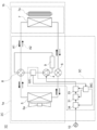
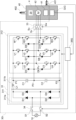
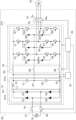
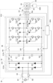
- FIG. 1 is a schematic diagram of a compressor and a control device of a refrigeration cycle device according to a first embodiment
- FIG. 1 is a waveform diagram of a voltage of a smoothing circuit of a drive circuit of a control device according to a first embodiment.
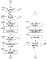
- 1 is a part of a flowchart of an operation of a control device according to a first embodiment.
- 1 is a part of a flowchart of an operation of a control device according to a first embodiment.
- 1 is a part of a flowchart of an operation of a control device according to a first embodiment.
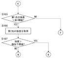
- 1 is a part of a flowchart of an operation of a control device according to a first embodiment.
- 1 is a part of a flowchart of an operation of a control device according to a first embodiment.
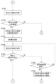
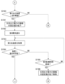
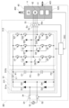
- FIG. 13 is a schematic diagram of a compressor and a control device of a refrigeration cycle device according to a second embodiment. Schematic diagram of a compressor motor according to a second embodiment. An explanatory diagram of the results of an experiment to verify whether or not a disproportionation reaction occurs 11 is a part of a flowchart of the operation of the control device according to the second embodiment. 11 is a part of a flowchart of the operation of the control device according to the second embodiment.
- 11 is a part of a flowchart of the operation of the control device according to the second embodiment. 11 is a part of a flowchart of the operation of the control device according to the third embodiment. 11 is a part of a flowchart of the operation of the control device according to the third embodiment. 11 is a part of a flowchart of the operation of the control device according to the third embodiment. 11 is a part of a flowchart of the operation of the control device according to the fourth embodiment. 11 is a part of a flowchart of the operation of the control device according to the fourth embodiment. 11 is a part of a flowchart of the operation of the control device according to the fourth embodiment. 11 is a part of a flowchart of the operation of the control device according to the fourth embodiment. 11 is a part of a flowchart of the operation of the control device according to the fourth embodiment. 11 is a part of a flowchart of the operation of the control device according to the fourth embodiment. 11 is a part of a flowchart of the operation
- FIG. 11 is a part of a flowchart of the operation of the control device according to the fourth embodiment. 11 is a part of a flowchart of the operation of the control device according to the fourth embodiment. 11 is a part of a flowchart of the operation of the control device according to the fourth embodiment. 11 is a part of a flowchart of the operation of the control device according to the fourth embodiment.
- FIG. 13 is a schematic diagram of a compressor and a control device of a refrigeration cycle device according to a fifth embodiment.
- FIG. 13 is a schematic diagram of the inside of a compressor of a refrigeration cycle device according to a fifth embodiment.
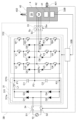
- FIG. 13 is a schematic diagram of a light detection circuit according to a fifth embodiment.
- FIG. 13 is a part of a flowchart of the operation of the control device according to the fifth embodiment.
- 13 is a part of a flowchart of the operation of the control device according to the fifth embodiment.
- 13 is a part of a flowchart of the operation of the control device according to the fifth embodiment.
- 13 is a part of a flowchart of the operation of the control device according to the fifth embodiment.
- 13 is a part of a flowchart of the operation of the control device according to the fifth embodiment.
- 13 is a part of a flowchart of the operation of the control device according to the fifth embodiment.
- FIG. 13 is a schematic diagram of a compressor and a control device of a refrigeration cycle device according to a sixth embodiment.
- FIG. 13 is a schematic diagram of a light detection circuit of a refrigeration cycle device according to a sixth embodiment.
- FIG. 13 is a schematic diagram of a compressor and a control device of a refrigeration cycle device according to a seventh embodiment.
- 13 is a schematic diagram of a light detection circuit of a refrigeration cycle device according to a seventh embodiment.
- Block diagram of a refrigeration cycle device according to an eighth embodiment FIG. 13 is a schematic diagram of a compressor and a control device of a refrigeration cycle device according to an eighth embodiment.
- An example of dye absorbance versus wavelength 13 is a schematic diagram of a light detection circuit of a refrigeration cycle apparatus according to an eighth embodiment.
- FIG. 13 is a schematic diagram of a compressor and a control device of a refrigeration cycle device according to a ninth embodiment.
- FIG. 13 is a schematic diagram of a light detection circuit of a refrigeration cycle apparatus according to a ninth embodiment.
- FIG. 13 is a schematic diagram of a compressor and a control device of a refrigeration cycle device according to a tenth embodiment. Schematic diagram of a control device according to a modified example.
- FIG. 1 is a schematic diagram of a compressor and a control device of a refrigeration cycle device according to a modified example.
- prefixes such as “first” and “second” are added to the names of the components.
- the prefixes such as “first” and “second” may be omitted in consideration of readability of the text.
- suffixes such as "-1" and “-2” are added to the symbols of the components.
- the suffixes "-1” and “-2” may be omitted in consideration of readability of the text.
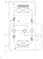
- 1.1 First embodiment 1.1.1 Configuration 1 is a block diagram of a refrigeration cycle apparatus 1 according to the present embodiment.
- the refrigeration cycle apparatus 1 constitutes, for example, an air conditioner capable of cooling operation and heating operation.
- the refrigeration cycle apparatus 1 includes a refrigeration cycle circuit 2 and a control device 3.
- the refrigeration cycle circuit 2 constitutes a flow path through which the working medium 20 (see FIG. 2) circulates.
- the working medium 20 contains an ethylene-based fluoroolefin as a refrigerant component.
- the ethylene-based fluoroolefin may be an ethylene-based fluoroolefin that undergoes a disproportionation reaction.
- Examples of the ethylene-based fluoroolefin that undergoes a disproportionation reaction include 1,1,2-trifluoroethylene (HFO1123), trans-1,2-difluoroethylene (HFO1132(E)), cis-1,2-difluoroethylene (HFO-1132(Z)), 1,1-difluoroethylene (HFO-1132a), tetrafluoroethylene (CF 2 ⁇ CF 2 , FO1114), and monofluoroethylene (HFO-1141). That is, the working medium 20 contains a refrigerant component that may undergo a disproportionation reaction.
- the working medium 20 may contain multiple types of refrigerant components.
- the working medium 20 may contain an ethylene-based fluoroolefin as a main refrigerant component and a compound other than an ethylene-based fluoroolefin as a secondary refrigerant component.
- secondary refrigerant components include hydrofluorocarbons (HFCs), hydrofluoroolefins (HFOs), saturated hydrocarbons, carbon dioxide, etc.
- hydrofluorocarbons examples include difluoromethane, difluoroethane, trifluoroethane, tetrafluoroethane, pentafluoroethane, pentafluorobutane, heptafluorocyclopentane, etc.
- hydrofluoroolefins examples include monofluoropropene, trifluoropropene, tetrafluoropropene, pentafluoropropene, hexafluorobutene, etc.
- saturated hydrocarbons examples include ethane, n-propane, cyclopropane, n-butane, cyclobutane, isobutane (2-methylpropane), methylcyclopropane, n-pentane, isopentane (2-methylbutane), neopentane (2,2-dimethylpropane), methylcyclobutane, etc.
- the working fluid 20 may further include a disproportionation inhibitor that suppresses the disproportionation reaction of the ethylene-based fluoroolefin.
- the disproportionation inhibitor include saturated hydrocarbons or haloalkanes.
- saturated hydrocarbons include ethane, n-propane, cyclopropane, n-butane, cyclobutane, isobutane (2-methylpropane), methylcyclopropane, n-pentane, isopentane (2-methylbutane), neopentane (2,2-dimethylpropane), methylcyclobutane, and the like.
- n-propane is preferred.
- haloalkanes examples include haloalkanes having 1 or 2 carbon atoms.
- haloalkanes having one carbon atom examples include (mono)iodomethane ( CH3I ), diiodomethane ( CH2I2 ), dibromomethane ( CH2Br2 ), bromomethane (CH3Br), dichloromethane ( CH2Cl2 ) , chloroiodomethane ( CH2ClI ), dibromochloromethane (CHBr2Cl), tetraiodomethane ( CI4 ), carbon tetrabromide ( CBr4 ), bromotrichloromethane ( CBrCl3 ) , dibromodichloromethane (CBr2Cl2 ) , tribromofluoromethane ( CBr3F ), fluorodiiodomethane ( CHFI
- haloalkanes having 2 carbon atoms examples include 1,1,1-trifluoro-2-iodoethane (CF 3 CH 2 I), monoiodoethane (CH 3 CH 2 I), monobromoethane (CH 3 CH 2 Br ), 1,1,1-triiodoethane (CH 3 CI 3 ), etc.
- the working fluid 20 may contain one or more types of haloalkanes having 1 or 2 carbon atoms. In other words, only one type of haloalkane having 1 or 2 carbon atoms may be used, or two or more types may be used in appropriate combination.
- a pressure sensor (GC61 manufactured by Nagano Keiki Co., Ltd.) was attached to a sealed pressure vessel (stainless steel sealed vessel, internal volume 50 mL) to measure the internal pressure in the pressure vessel, a thermocouple (PL thermocouple ground PL-18-K-A 4-T manufactured by Conax Technologies) to measure the internal temperature in the pressure vessel, and a discharge device to generate a discharge in the pressure vessel.
- a gas cylinder of 1,1,2-trifluoroethylene was connected so that the pressure could be adjusted.
- a mantle heater was installed to heat the entire pressure vessel, and a ribbon heater (flexible ribbon heater 1 m, 200 W manufactured by Tokyo Institute of Technology Co., Ltd.) was installed to heat the piping as well. This constructed an experimental system for the disproportionation reaction.
- Table 1 below shows whether or not a disproportionation reaction occurs when the working fluid is 1,1,2-trifluoroethylene alone (Examples 1 and 2), a mixed gas adjusted to have a 1,1,2-trifluoroethylene content of 80% by mass and an n-propane content of 20% by mass (Example 3), a mixed gas adjusted to have a 1,1,2-trifluoroethylene content of 91.5% by mass, an n-propane content of 7.5% by mass, and a difluoroiodomethane content of 1.0% by mass (Example 4), and a mixed gas adjusted to have a 1,1,2-trifluoroethylene content of 69.5% by mass, a difluoromethane content of 22% by mass, an n-propane content of 7.5% by mass, and a difluoroiodomethane content of 1.0% by mass (Example 5).
- the pressure was adjusted to 2 MPa in Examples 1 and 2, and 6 MPa in Examples 3 to 5.
- the stored energy in Table 1 is the electrostatic energy stored in the capacitor installed inside the discharge device.
- the number of discharges is the number of times discharged at regular intervals under the conditions in question. If a disproportionation reaction was observed after that number of discharges, the disproportionation reaction was recorded as "Yes.” If no disproportionation reaction was observed, the disproportionation reaction was recorded as "No.”
- Example 1 From Table 1, no disproportionation reaction was observed in Example 1. Therefore, it was confirmed that there is an extremely low possibility of a disproportionation reaction occurring in minor discharges where the stored energy is less than 0.5 J. Also, from Table 1, a disproportionation reaction was observed in Example 2. Therefore, it was confirmed that when the stored energy is large, there is a high possibility of a disproportionation reaction occurring after two consecutive discharges. Table 1 shows that the greater the stored energy, that is, the more energy is consumed in discharging, the higher the possibility of a disproportionation reaction occurring. This shows that in order to suppress a disproportionation reaction, it is preferable to keep the discharge state at a minor level, that is, to detect it early and suppress the disproportionation reaction.
- Example 3 uses a larger stored energy than Example 2, in which disproportionation was observed in 1,1,2-trifluoroethylene alone. Therefore, it was confirmed that in a working medium containing n-propane as a disproportionation inhibitor, that is, even when the stored energy is increased by the disproportionation inhibitor, the possibility of a disproportionation reaction occurring in a small, minor discharge is extremely low. This shows that in order to suppress disproportionation reactions in a working medium of a mixed gas containing a disproportionation inhibitor, it is preferable to keep the discharge in a minor state, that is, to detect it early and suppress the disproportionation reaction.
- Example 4 uses a larger stored energy than Example 2, in which disproportionation was observed in 1,1,2-trifluoroethylene alone. Therefore, it was confirmed that in a working medium containing difluoroiodomethane as a disproportionation inhibitor other than n-propane, that is, in the case where the stored energy is increased by two or more disproportionation inhibitors, the possibility of a disproportionation reaction occurring in a small, minor discharge is extremely low.
- Example 5 uses a larger stored energy than Example 2, in which disproportionation was confirmed in 1,1,2-trifluoroethylene alone. Therefore, it was confirmed that the stored energy is increased by two or more disproportionation inhibitors, and that even in a working medium containing a secondary refrigerant component that does not cause disproportionation, the possibility of a disproportionation reaction occurring in a small, minor discharge is extremely low.
- the refrigeration cycle circuit 2 includes a compressor 4, a first heat exchanger 5, an expansion valve 6, a second heat exchanger 7, and a four-way valve 8.
- the refrigeration cycle device 1 includes an outdoor unit 1a and an indoor unit 1b.
- the outdoor unit 1a includes a control device 3, a compressor 4, a first heat exchanger 5, an expansion valve 6, and a four-way valve 8.
- the outdoor unit 1a further includes a first blower 5a for promoting heat exchange in the first heat exchanger 5.
- the indoor unit 1b includes a second heat exchanger 7.
- the indoor unit 1b further includes a second blower 7a for promoting heat exchange in the second heat exchanger 7.
- the compressor 4 compresses the working medium to increase the pressure of the working medium.
- the compressor 4 will be described in detail later.
- the first heat exchanger 5 and the second heat exchanger 7 exchange heat between the working medium circulating through the refrigeration cycle circuit 2 and external air (e.g., outside air or room air).
- the expansion valve 6 adjusts the pressure (evaporation pressure) of the working medium and the flow rate of the working medium.
- the four-way valve 8 switches the direction of the working medium circulating through the refrigeration cycle circuit 2 between a first direction corresponding to cooling operation and a second direction corresponding to heating operation.
- the first direction is the direction in which the working medium circulates through the refrigeration cycle circuit 2, in the order of the compressor 4, the first heat exchanger 5, the expansion valve 6, and the second heat exchanger 7, as shown by the solid arrow A1 in Figure 1.
- the compressor 4 compresses and discharges the gaseous working medium, which is then sent to the first heat exchanger 5 via the four-way valve 8.
- the first heat exchanger 5 exchanges heat between the outside air and the gaseous working medium, causing the gaseous working medium to condense and become liquefied.
- the liquid working medium is decompressed by the expansion valve 6 and sent to the second heat exchanger 7.
- heat exchange occurs between the liquid working medium and the indoor air, causing the liquid working medium to evaporate and become a gaseous working medium.
- the gaseous working medium returns to the compressor 4 via the four-way valve 8.
- the first heat exchanger 5 functions as a condenser
- the second heat exchanger 7 functions as an evaporator. Therefore, during cooling, the indoor unit 1b blows air cooled by heat exchange in the second heat exchanger 7 into the room.
- the second direction is the direction in which the working medium circulates through the refrigeration cycle circuit 2, in the order of the compressor 4, the second heat exchanger 7, the expansion valve 6, and the first heat exchanger 5, as shown by the dashed arrow A2 in Figure 1.
- the compressor 4 compresses and discharges the gaseous working medium, which is then sent to the second heat exchanger 7 via the four-way valve 8.
- the second heat exchanger 7 exchanges heat between the indoor air and the gaseous working medium, causing the gaseous working medium to condense and become liquefied.
- the liquid working medium is decompressed by the expansion valve 6 and sent to the first heat exchanger 5.
- heat exchange occurs between the liquid working medium and the outside air, causing the gaseous working medium to evaporate and become a gaseous working medium.
- the gaseous working medium returns to the compressor 4 via the four-way valve 8.
- the first heat exchanger 5 functions as an evaporator
- the second heat exchanger 7 functions as a condenser. Therefore, during heating, the indoor unit 1b blows air warmed by heat exchange in the second heat exchanger 7 into the room.
- the control device 3 controls the compressor 4 of the refrigeration cycle circuit 2.
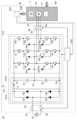
- Figure 2 is a schematic diagram of the compressor 4 and the control device 3.
- the compressor 4 is, for example, a hermetic compressor.
- the compressor 4 may be of a rotary type, a scroll type, or any other known type.
- the compressor 4 includes a hermetic container 40, a compression mechanism 41, and an electric motor 42.
- the sealed container 40 forms a flow path for the working medium 20.
- the sealed container 40 has a suction pipe 401 and a discharge pipe 402.
- the working medium 20 is sucked into the sealed container 40 from the suction pipe 401, compressed by the compression mechanism 41, and then discharged from the discharge pipe 402 to the outside of the sealed container 40.
- the inside of the sealed container 40 is filled with high-temperature, high-pressure working medium 20 and lubricating oil.
- the bottom of the sealed container 40 forms an oil storage section that stores a mixture of the working medium 20 and lubricating oil.
- the compression mechanism 41 is located inside the sealed container 40 and compresses the working medium.
- the compression mechanism 41 may have a conventionally known configuration.
- the compression mechanism 41 has, for example, a cylinder that forms a compression chamber, a rolling piston that is disposed in the compression chamber inside the cylinder, and a crankshaft that is connected to the rolling piston.
- the electric motor 42 is located inside the sealed container 40 and operates the compression mechanism 41.
- the electric motor 42 is, for example, a brushless motor (three-phase brushless motor).
- the electric motor 42 includes, for example, a rotor fixed to the crankshaft of the compression mechanism 41 and a stator provided around the rotor.
- the stator is, for example, configured by concentrating or dispersing a stator winding (magnet wire, etc.) around a stator core (electromagnetic steel plate, etc.) with an insulating material such as insulating paper interposed between the stator winding.
- the stator winding is covered with an insulating material. Examples of insulating materials include polyethylene terephthalate (PET), polyethylene naphthalate (PEN), aramid polymer, polyphenylene sulfide (PPS), polytetrafluoroethylene (PTFE), etc.
- the compressor 4 may be provided with an accumulator to prevent liquid compression in the compression chamber of the compression mechanism 41.
- the accumulator separates the working medium into a gaseous working medium and a liquid working medium, and guides only the gaseous working medium from the suction pipe 401 into the inside of the sealed container 40.
- the control device 3 includes a drive circuit 31 and a control circuit 35.
- the drive circuit 31 drives the electric motor 42 based on the input power from the power source 10.
- the power source 10 is an AC power source
- the input power is AC power.
- the drive circuit 31 includes a converter circuit 311 and an inverter circuit 312.
- the converter circuit 311 outputs DC output power based on the input power from the power source 10 so that the voltage becomes a first voltage. In other words, the converter circuit 311 converts the input power into DC output power so that the voltage of the DC output power becomes the first voltage.
- the first voltage corresponds to the rated voltage of the drive circuit 31.
- the converter circuit 311 includes a rectifier circuit 311a and a smoothing circuit 311b.
- the rectifier circuit 311a is a diode bridge composed of multiple diodes D1 to D4.
- the power source 10 is connected between the input terminals of the rectifier circuit 311a (the connection point of diodes D1, D2, and the connection point of diodes D3, D4), and the smoothing circuit 311b is connected between the output terminals of the rectifier circuit 311a (the connection point of diodes D1, D3, and the connection point of diodes D2, D4).
- the smoothing circuit 311b smoothes and outputs the voltage between the output terminals of the rectifier circuit 311a.
- the smoothing circuit 311b sets the voltage of the DC output power to a first voltage.
- the smoothing circuit 311b includes a series circuit of an inductor L1 and smoothing capacitors C1 and C2.
- the connection point between the inductor L1 and the smoothing capacitor C1 is the first output point P1 that outputs a voltage corresponding to the first voltage.
- the connection point between the connection point of the diodes D2 and D4 and the smoothing capacitor C2 is the second output point P2 that outputs a voltage lower than the voltage at the first output point P1.
- the connection point between the smoothing capacitor C1 and the smoothing capacitor C2 is the third output point P3 that outputs a voltage between the voltage at the first output point P1 and the voltage at the second output point P2.
- the first output point P1 is a high voltage point
- the second output point P2 is a low voltage point
- the third output point P3 is an intermediate voltage point.
- the smoothing capacitors C1 and C2 have the same capacitance.
- the voltage between the voltage at the first output point P1 and the voltage at the third output point P3 is equal to the voltage between the voltage at the second output point P2 and the voltage at the third output point P3. If the voltage between the first output point P1 and the second output point P2 (which corresponds to the first voltage) is E, the voltage between the first output point P1 and the third output point P3 is E/2, and similarly, the voltage between the second output point P2 and the third output point P3 is E/2. This allows the drive circuit 31 to provide five levels of voltage: E, E/2, 0, -E/2, and -E.
- the inverter circuit 312 outputs AC output power to the motor 42 based on the DC output power from the converter circuit 311.
- the AC output power is three-phase AC power.
- the inverter circuit 312 includes a plurality of semiconductor switching elements U1 to U4, V1 to V4, and W1 to W4.
- the semiconductor switching elements U1 to U4, V1 to V4, and W1 to W4 are, for example, transistors.
- the semiconductor switching elements U1 to U4, V1 to V4, and W1 to W4 each form a series circuit and are connected between the first output point P1 and the second output point P2.
- connection point of the semiconductor switching elements U1 and U2, the connection point of the semiconductor switching elements V1 and V2, and the connection point of the semiconductor switching elements W1 and W2 are connected to the third output point P3 via diodes D5, D7, and D9, respectively.
- the anodes of diodes D5, D7, and D9 are connected to the third output point P3, and the cathodes of diodes D5, D7, and D9 are connected to the connection point of semiconductor switching elements U1 and U2, the connection point of semiconductor switching elements V1 and V2, and the connection point of semiconductor switching elements W1 and W2, respectively.
- connection point of the semiconductor switching elements U2, U3 constitutes the U-phase output terminal Pu, which is connected to the U-phase input terminal of the motor 42.
- the connection point of the semiconductor switching elements V2, V3 constitutes the V-phase output terminal Pv, which is connected to the V-phase input terminal of the motor 42.
- the connection point of the semiconductor switching elements W2, W3 constitutes the W-phase output terminal Pw, which is connected to the W-phase input terminal of the motor 42.
- connection point of the semiconductor switching elements U3 and U4, the connection point of the semiconductor switching elements V3 and V4, and the connection point of the semiconductor switching elements W3 and W4 are connected to the third output point P3 via diodes D6, D8, and D10, respectively.
- the cathodes of diodes D6, D8, and D10 are connected to the third output point P3, and the anodes of diodes D6, D8, and D10 are connected to the connection point of semiconductor switching elements U3 and U4, the connection point of semiconductor switching elements V3 and V4, and the connection point of semiconductor switching elements W3 and W4, respectively.
- the semiconductor switching elements U1, U2, V1, V2, W1, and W2 constitute a first semiconductor switching element group connected between the first output point P1 and the motor 42.
- the semiconductor switching elements U1 and U2 constitute a U-phase first semiconductor switching element group connected between the first output point P1 and the U-phase input terminal of the motor 42.
- the semiconductor switching elements V1 and V2 constitute a V-phase first semiconductor switching element group connected between the first output point P1 and the V-phase input terminal of the motor 42.
- the semiconductor switching elements W1 and W2 constitute a W-phase first semiconductor switching element group connected between the first output point P1 and the W-phase input terminal of the motor 42.
- the semiconductor switching elements U3, U4, V3, V4, W3, and W4 constitute a second semiconductor switching element group connected between the second output point P2 and the motor 42.
- the semiconductor switching elements U3 and U4 constitute a U-phase second semiconductor switching element group connected between the second output point P2 and the U-phase input terminal of the motor 42.
- the semiconductor switching elements V3 and V4 constitute a V-phase second semiconductor switching element group connected between the second output point P2 and the V-phase input terminal of the motor 42.
- the semiconductor switching elements W3 and W4 constitute a W-phase second semiconductor switching element group connected between the second output point P2 and the W-phase input terminal of the motor 42.
- the semiconductor switching elements U2, U3, V2, V3, W2, and W3 constitute a third semiconductor switching element group connected between the third output point P3 and the motor 42.
- the semiconductor switching elements U2 and U3 constitute a U-phase third semiconductor switching element group connected between the third output point P3 and the U-phase input terminal of the motor 42.
- the semiconductor switching elements V2 and V3 constitute a V-phase third semiconductor switching element group connected between the third output point P3 and the V-phase input terminal of the motor 42.
- the semiconductor switching elements W2 and W3 constitute a W-phase third semiconductor switching element group connected between the third output point P3 and the W-phase input terminal of the motor 42.
- the converter circuit 311 has a plurality of output points including the first to third output points P1 to P3.
- the inverter circuit 312 has a plurality of semiconductor switching element groups including a first semiconductor switching element group (semiconductor switching elements U1, U2, V1, V2, W1, W2) connected between the first output point P1 and the motor 42, a second semiconductor switching element group (semiconductor switching elements U3, U4, V3, V4, W3, W4) connected between the second output point P2 and the motor 42, and a third semiconductor switching element group (semiconductor switching elements U2, U3, V2, V3, W2, W3) connected between the third output point P3 and the motor 42.
- the drive circuit 31 is a so-called multilevel inverter, in particular a three-level inverter.
- the voltage detector 32 detects the DC output power of the converter circuit 311 and outputs a detection voltage indicating the voltage of the DC output power.
- the voltage detector 32 includes a voltage divider circuit connected between the output terminals of the smoothing circuit 311b of the converter circuit 311, that is, between the first output point P1 and the second output point P2, and outputs the detection voltage based on the voltage obtained from the voltage divider circuit.
- the voltage detector 32 may also output the detection voltage based on the output of the voltage divider circuit and the differential amplifier.
- the non-inverting input terminal and the inverting input terminal of the differential amplifier are connected to both ends of the resistor of the voltage divider circuit, respectively, and the differential amplifier can output the voltage across the resistor as the detection voltage.
- the position at which the voltage detector 32 is connected to the drive circuit 31 is not particularly limited, and may be any position at which the DC output power of the converter circuit 311 can be detected.
- the position at which the DC output power of the converter circuit 311 can be detected is not limited to within the converter circuit 311, but may be a position within the inverter circuit 312 that is equivalent in circuit terms to the first output point P1 and the second output point P2.
- the voltage divider circuit of the voltage detector 32 can employ a conventionally known configuration, so a detailed description is omitted.
- the first protection device 33 is provided to stop the output of AC output power.
- the first protection device 33 includes switches Su, Sv, and Sw interposed between the drive circuit 31 and the motor 42.
- the switches Su, Sv, and Sw are connected between the U-phase, V-phase, and W-phase input terminals of the motor 42 and the U-phase output terminals Pu, Pv, and Pw, respectively.
- the switches Su, Sv, and Sw may be controllable switches such as semiconductor switches and electromagnetic relays.
- the first protection device 33 When the switches Su, Sv, and Sw are closed in the on state, the first protection device 33 enables the output of AC output power from the drive circuit 31 to the motor 42, and when the switches Su, Sv, and Sw are open in the off state, the first protection device 33 stops the output of AC output power from the drive circuit 31 to the motor 42.
- the second protection device 34 is provided to stop the input of input power.
- the second protection device 34 includes switches S1 and S2 interposed between the drive circuit 31 and the power source 10.
- the switches S1 and S2 are respectively connected between the input terminal of the rectifier circuit 311a and the power source 10.
- the switches S1 and S2 may be, for example, a controllable switch such as a semiconductor switch or an electromagnetic relay.
- the control circuit 35 may be realized by, for example, a computer system including at least one processor (microprocessor) and one or more memories.
- the computer system may include one or more A/D converters.
- the one or more A/D converters are used to convert the detected voltage from the voltage detector 32 from analog to digital format.
- the control circuit 35 controls the drive circuit 31, the first protection device 33, and the second protection device 34.
- the control circuit 35 executes PWM control of a group of multiple semiconductor switching elements of the inverter circuit 312 of the drive circuit 31 so that the drive circuit 31 operates the electric motor 42.
- control circuit 35 controls the switching of the multiple semiconductor switching elements U1 to U4, V1 to V4, and W1 to W4 of the inverter circuit 312 of the drive circuit 31 so that the inverter circuit 312 supplies AC output power (three-phase AC power) to the electric motor 42 based on the DC output power from the smoothing circuit 311b.
- the semiconductor switching elements U1 to U4 have a first state in which the semiconductor switching elements U1 and U2 are on and the semiconductor switching elements U3 and U4 are off, a second state in which the semiconductor switching elements U3 and U4 are on and the semiconductor switching elements U1 and U2 are off, and a third state in which the semiconductor switching elements U2 and U3 are on and the semiconductor switching elements U1 and U4 are off.
- the voltage at the U-phase output terminal Pu is E/2 in the first state, -E/2 in the second state, and 0 in the third state.
- the semiconductor switching elements V1 to V4 There are three states for the semiconductor switching elements V1 to V4: a first state in which the semiconductor switching elements V1 and V2 are on and the semiconductor switching elements V3 and V4 are off; a second state in which the semiconductor switching elements V3 and V4 are on and the semiconductor switching elements V1 and V2 are off; and a third state in which the semiconductor switching elements V2 and V3 are on and the semiconductor switching elements V1 and V4 are off.
- the voltage at the V-phase output terminal Pv is E/2 in the first state, -E/2 in the second state, and 0 in the third state.
- the semiconductor switching elements W1 to W4 have a first state in which the semiconductor switching elements W1 and W2 are on and the semiconductor switching elements W3 and W4 are off, a second state in which the semiconductor switching elements W3 and W4 are on and the semiconductor switching elements W1 and W2 are off, and a third state in which the semiconductor switching elements W2 and W3 are on and the semiconductor switching elements W1 and W4 are off.
- the voltage at the W-phase output terminal Pw is E/2 in the first state, -E/2 in the second state, and 0 in the third state.
- the drive circuit 31 can provide five voltage levels: E, E/2, 0, -E/2, and -E.
- the control circuit 35 controls the switching of the semiconductor switching elements U1-U4, V1-V4, W1-W4 of the inverter circuit 312 of the drive circuit 31 based on, for example, U-phase, V-phase, and W-phase output voltage command values corresponding to the sine wave AC voltages of the U-phase, V-phase, and W-phase of the three-phase AC, respectively, and the first and second carrier triangular waves.
- the value of the first carrier triangular wave is 0 or more, and the value of the second carrier triangular wave is 0 or less.
- the drive circuit 31 can provide five levels of voltage: E, E/2, 0, -E/2, and -E, so that the voltage between the U-phase input terminal and the V-phase input terminal of the motor 42, the voltage between the V-phase input terminal and the W-phase input terminal of the motor 42, and the voltage between the W-phase input terminal and the U-phase input terminal of the motor 42 can each be made closer to a sine wave.
- the control circuit 35 further executes processing to suppress the disproportionation reaction of the working medium 20 circulating through the refrigeration cycle circuit 2 based on the detected voltage from the voltage detector 32.
- the causes of the disproportionation reaction of the working medium 20 are thought to be heat and radicals. For example, when radicals are generated under high temperature and pressure, the disproportionation reaction of the working medium 20 is thought to proceed. Radicals may be generated, for example, by a discharge phenomenon that may occur when some abnormality occurs in the compressor 4 or the drive circuit 31.
- the disproportionation reaction of the working medium 20 proceeds starting from a discharge phenomenon, the generation of plasma or a reaction fireball is observed in the working medium 20. Then, the disproportionation reaction of the working medium 20 produces products from the working medium 20.
- the products may include intermediate products or final products.
- the final products refer to thermodynamically stable chemical species among the chemical species produced in the disproportionation reaction of the working medium 20.
- thermodynamically stable means that the type and composition of the compound do not change when exposed to a high temperature of 2000K or more at 1 atmosphere for a predetermined time (for example, about 10 minutes) and then returned to normal temperature and pressure.
- the intermediate products refer to thermodynamically unstable chemical species among the chemical species produced in the disproportionation reaction of the working medium 20.
- Thermodynamically unstable means that at least one of the type or composition of the compound changes when exposed to a high temperature of 2000K or more at 1 atmosphere.
- Thermodynamically unstable chemical species also include so-called metastable chemical species.
- the intermediate product is a chemical species that may exist with a lifespan of 1 ms or more among the chemical species generated in the disproportionation reaction of the working medium 20, but may decompose at high temperatures (e.g., 2000 K or higher) to generate a final product. Naturally, such intermediate products do not include the final product.
- the lifespan here is the lifespan in a measurement environment equivalent to the inside of the refrigeration cycle circuit 2.
- the conditions for measuring the lifespan are a maximum temperature of 500 K and a maximum pressure of 6 MPa.
- the intermediate products include carbenes, carbene inserts (compounds produced by the insertion reaction of carbene), tetrafluoroethylene, perfluoroolefins, and fluorobenzene.
- the final products include soot, hydrogen fluoride, and tetrafluoromethane.
- a sign of a disproportionation reaction can be detected based on at least one of the first state of the drive circuit 31 that drives the compressor 4 of the refrigeration cycle circuit 2 and the second state of the working medium 20.
- the first state is a state of the drive circuit 31 that can be used to determine the occurrence of a discharge phenomenon in the compressor 4.
- the second state is a state of the working medium 20 that can be used to determine the light emission of the working medium 20 due to the generation of plasma or a reaction fireball, or the amount of products generated from the working medium 20.
- the sign of a disproportionation reaction here means a sign of the propagation of a disproportionation reaction throughout the working medium 20, rather than a sign of a local disproportionation reaction in the working medium 20. In other words, if local disproportionation reactions occur frequently, there is a risk that the disproportionation reaction will eventually spread throughout the working medium 20.
- FIG. 3 is a waveform diagram of the voltage of the DC output power of the converter circuit 311.
- the voltage of the DC output current gradually decreases at times t11 to t12, t21 to t22, t31 to t32, t41 to t42, and t51 to t52, but this voltage decrease is due to the switching of the semiconductor switching elements U1 to U4, V1 to V4, and W1 to W4 of the inverter circuit 312.
- the switching frequency of the inverter circuit 312 is, for example, 1.0 kHz to 5.0 kHz
- the time between time t11 and time t21 is about 0.2 to 1.0 ms.
- a sudden drop in the voltage of the DC output current is observed, which is thought to be due to the occurrence of a discharge phenomenon.
- control circuit 35 determines whether a discharge phenomenon has occurred based on the detected voltage from the voltage detector 32, and if it determines that a discharge phenomenon has occurred, it stops or limits the operation of the drive circuit 31 to suppress the disproportionation reaction of the working medium circulating through the refrigeration cycle circuit 2.
- the control device 3 detects the signs of a disproportionation reaction based on the changes occurring in the DC output power (voltage of the smoothing circuit 311b) inside the drive circuit 31, not on the changes occurring in the current actually flowing from the drive circuit 31 to the motor 42.
- the time scale of the discharge phenomenon is shorter than the time scale of smoothing (rectification) in the drive circuit 31.
- the time scale of the discharge phenomenon is on the order of ⁇ s. Therefore, it is possible to determine whether a discharge phenomenon is occurring based on the DC output power inside the drive circuit 31.
- the measurement of the DC output power (voltage of the smoothing circuit 311b) inside the drive circuit 31 can be performed in a shorter time and at a shorter cycle than the measurement of the current actually flowing from the drive circuit 31 to the motor 42. This enables the earlier detection of the signs of a disproportionation reaction of the working medium 20. If the signs of a disproportionation reaction of the working medium 20 can be detected earlier in this way, the disproportionation reaction can be suppressed earlier, thereby improving the suppression of the disproportionation reaction.
- the control circuit 35 stops or limits the operation of the drive circuit 31 when the detected voltage falls below a second voltage that is equal to or lower than the first voltage.
- the second voltage is set to determine whether a discharge phenomenon has occurred, which may occur when some abnormality occurs in the compressor 4 or the drive circuit 31. Referring to FIG. 3, if the normal voltage (first voltage) of the DC output current is E, it has been observed that the voltage of the DC output current becomes 0.8E or less, or even 0.3E or less, due to a discharge phenomenon. From this point of view, it is preferable that the second voltage is 0.3 times or more and 0.8 times or less than the first voltage. In this embodiment, the second voltage is 0.8 times the first voltage.
- the voltage detector 32 detects the DC output power and outputs a detected voltage indicating the voltage of the DC output power as a first state.
- the control circuit 35 detects a sign of a disproportionation reaction based on the first state related to the drive circuit 31, it stops or limits the operation of the refrigeration cycle circuit 2.
- the control circuit 35 determines the number of times that a discharge phenomenon has occurred in the compressor 4 based on the number of times that the detected voltage has fallen below a second voltage that is equal to or lower than the first voltage.
- a sign of a disproportionation reaction is when the number of times that a discharge phenomenon has occurred is equal to or greater than a predetermined number.
- Stopping or limiting the operation of the refrigeration cycle circuit 2 may include stopping the operation of the drive circuit 31, increasing the rotation speed of the condenser fan, decreasing the rotation speed of the evaporator fan, increasing the opening of the expansion valve, (if the refrigeration cycle device 1 has multiple indoor units 1b) opening the expansion valve of at least one of the indoor units 1b that are out of operation, and (in the case of heating operation) switching to cooling operation via the four-way valve 8 and opening the expansion valve 6.
- the operation of the drive circuit 31 can be stopped by either stopping the output of AC output power, stopping the output of DC output power, or stopping the input of input power.
- the control circuit 35 sets the first protection device 33 to the OFF state to electrically isolate the motor 42 from the drive circuit 31 and stop the output of AC output power.
- the control circuit 35 sets the first protection device 33 to the ON state to connect the motor 42 to the drive circuit 31.
- the control circuit 35 sets the second protection device 34 to the OFF state to electrically isolate the power source 10 from the drive circuit 31 and stop the output of AC output power.
- the control circuit 35 sets the second protection device 34 to the ON state to connect the power source 10 to the drive circuit 31.
- the operation of the drive circuit 31 can be restricted by lowering the set value of the amplitude of the AC output power or the set value of the frequency of the AC output power.
- the control circuit 35 controls the drive circuit 31 to lower the set value of the amplitude of the AC output power.
- the drive circuit 31 can provide five levels of voltage: E, E/2, 0, -E/2, and -E, so the set value of the amplitude of the AC output power is changed from E to E/2. In this case, the rotation speed of the motor 42 is reduced compared to when the set value of the amplitude of the AC output power is E.
- control circuit 35 sets the second protection device 34 to the OFF state to electrically isolate the power source 10 from the drive circuit 31 and stop the output of AC output power.
- the control circuit 35 sets the second protection device 34 to the ON state to connect the power source 10 to the drive circuit 31.
- the control circuit 35 stops or limits the operation of the drive circuit 31 in different ways depending on the number of times the detected voltage falls below the second voltage.
- the control circuit 35 executes processing that suppresses the disproportionation reaction to a higher degree as the number of times the detected voltage falls below the second voltage increases. This enables the control device 3 to suppress the disproportionation reaction even when relatively minor discharge phenomena occur consecutively within a short period of time. For example, it is possible to prevent disproportionation reactions from being induced beyond a predetermined energy due to consecutive occurrences of low-energy abnormal states (discharges), thereby improving the safety of using the working medium 20.
- the control circuit 35 stops or limits the operation of the drive circuit 31 in different ways depending on the time difference between the first time when the detected voltage first becomes less than the second voltage and the second time when the detected voltage next becomes less than the second voltage.
- the control circuit 35 executes processing that suppresses the disproportionation reaction to a higher degree the shorter the time difference. This enables the control device 3 to suppress the disproportionation reaction even when relatively minor discharge phenomena occur consecutively within a short period of time. This prevents, for example, a disproportionation reaction from being induced beyond a predetermined energy due to consecutive occurrences of low-energy abnormal states (discharges), improving the safety of using the working medium 20.
- the process for suppressing the disproportionation reaction includes, for example, the first process to the third process.
- the first process is a process for stopping the output of AC output power and resuming the output of AC output power after a standby time has elapsed.
- the second process is a process for stopping the output of AC output power and operating with a lower set value of the amplitude of the AC output power after a standby time has elapsed.
- the third process is a process for stopping the output of AC output power and stopping the input of input power.
- the degree of suppression of the disproportionation reaction increases in the order of the third process, the second process, and the first process. In the first or second process, the longer the standby time, the higher the degree of suppression of the disproportionation reaction.
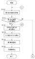
- the control circuit 35 outputs AC output power to the motor 42 based on the input power of the power source 10 via the drive circuit 31 to drive the compressor 4.
- the control circuit 35 sets the number of abnormalities to 0 (S10).
- the number of abnormalities indicates the number of times the detected voltage is less than the second voltage.
- the number of abnormalities is an indicator of the likelihood of a disproportionation reaction occurring.
- the control circuit 35 acquires the detected voltage from the voltage detector 32 (S11). The control circuit 35 determines whether the detected voltage is less than the second voltage (S12).
- the control circuit 35 determines whether the detected voltage is less than the second voltage at a predetermined period. It is preferable that the predetermined period here is shorter than the period corresponding to the reference frequency of the inverter circuit 312 (e.g., 1000 to 5000 Hz).
- step S12 if the detected voltage is less than the second voltage (S12: YES), the control circuit 35 adds 1 to the number of abnormalities (S13) and determines whether the number of abnormalities is 1 or less (S14).
- step S14 If the number of abnormalities is 1 or less in step S14 (S14: YES), the control circuit 35 sets the first protection device 33 to the OFF state to stop the output of AC output power (S15). The control circuit 35 determines whether a first standby time has elapsed since the output of AC output power was stopped (S16). The first standby time is, for example, 1 s. When the first standby time has elapsed (S16: YES), the control circuit 35 sets the first protection device 33 to the ON state to resume the output of AC output power (S17), thereby resuming operation of the compressor 4 (S18). Then, the process returns to step S11.
- control circuit 35 stops outputting the AC output power when the detected voltage becomes less than the second voltage, and resumes outputting the AC output power when the first standby time has elapsed since the output of the AC output power was stopped.
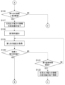
- step S14 if the number of abnormalities is not 1 or less (S14: NO), referring to FIG. 5, the control circuit 35 determines whether the time difference between the first time when the detected voltage first becomes less than the second voltage and the second time when the detected voltage next becomes less than the second voltage is within a first predetermined time (step S19).
- the shortness of the time difference is an indicator of the likelihood of a disproportionation reaction occurring.
- the first predetermined time is, for example, about 100 times the period corresponding to the reference frequency of the inverter circuit 312, and is about 20 to 100 ms.
- step S19 if the time difference is within the first predetermined time (step S19: YES), the control circuit 35 sets the first protection device 33 to the OFF state to stop the output of AC output power (S20). The control circuit 35 sets the second protection device 34 to the OFF state to stop the input of input power (S21). The control circuit 35 outputs a first abnormality notification (S22).
- the first abnormality notification indicates that an abnormality has occurred in the refrigeration cycle device 1 that is highly likely to cause a disproportionation reaction.
- the first abnormality notification is output to, for example, the control circuit of the indoor unit 1b and a remote controller. After this, the control circuit 35 stops the operation of the compressor 4 (S23).
- the control circuit 35 stops the output of the AC output power (S20) and stops the input of the input power (S21).
- step S19 the control circuit 35 determines whether the time difference is within a second predetermined time that is longer than the first predetermined time (step S24).
- the second predetermined time is, for example, about 1000 times the period corresponding to the reference frequency of the inverter circuit 312, and is about 200 ms to 1 s.
- step S24 if the time difference is within the second predetermined time (step S24: YES), the control circuit 35 sets the first protection device 33 to the off state to stop the output of the AC output power (S25).
- the control circuit 35 changes the switching control of the semiconductor switching element of the drive circuit 31 so that the set value of the amplitude of the AC output power decreases from E to E/2 (S26).
- the control circuit 35 outputs a second abnormality notification (S27).
- the second abnormality notification indicates that an abnormality that is likely to cause a disproportionation reaction has occurred in the refrigeration cycle device 1.
- the second abnormality notification is output to, for example, the control circuit and remote controller of the indoor unit 1b.
- the control circuit 35 determines whether a fourth waiting time has elapsed since the output of the AC output power was stopped (S28).
- the fourth waiting time is longer than the first waiting time.
- the fourth waiting time is, for example, 60 seconds.
- the control circuit 35 sets the first protection device 33 to an ON state to resume the output of the AC output power (S29), thereby resuming the operation of the compressor 4 (S30). In this case, the set value of the amplitude of the AC output power remains lowered from E to E/2.
- the control circuit 35 stops the output of the AC output power (S25) and reduces the set value of the amplitude of the AC output power (S26). If a fourth standby time, which is longer than the first standby time, has elapsed since the output of the AC output power was stopped, the control circuit 35 resumes the output of the AC output power while keeping the set value of the amplitude of the AC output power reduced (S29).
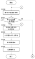
- control circuit 35 acquires the detected voltage from the voltage detector 32 (S31). The control circuit 35 determines whether the detected voltage is less than the second voltage (S32).
- step S32 If the detected voltage is less than the second voltage in step S32 (S32: YES), proceed to step S20 in FIG. 5.
- step S32 if the detected voltage is not less than the second voltage (S32: NO), the control circuit 35 determines whether the second monitoring time has elapsed since the compressor 4 restarted operating (S33).
- step S33 if the second monitoring time has elapsed since the compressor 4 restarted operating (S33: YES), the control circuit 35 cancels the reduction in the set value of the amplitude of the AC output power, returns the set value of the amplitude of the AC output power to E (S34), and proceeds to step S11 in FIG. 4.
- step S33 if the second monitoring time has not elapsed since the compressor 4 restarted operation (S33: NO), the process returns to step S31.
- steps S31 to S33 if the detected voltage falls below the second voltage between the time when compressor 4 restarts operation and the time when the second monitoring time has elapsed, the process proceeds to step S20 in FIG. 5, and if the detected voltage does not fall below the second voltage between the time when compressor 4 restarts operation and the time when the second monitoring time has elapsed, the process proceeds to step S34.
- the control circuit 35 cancels the reduction in the set value of the amplitude of the AC output power (S34). If the detected voltage becomes less than the second voltage before the second monitoring time has elapsed after the output of the AC output power is resumed after the fourth waiting time has elapsed (S29) (YES in S32), the control circuit 35 stops the output of the AC output power (S20) and stops the input of the input power (S21).
- step S35 the control circuit 35 determines whether the time difference is within a third predetermined time that is longer than the second predetermined time (step S35).
- the third predetermined time is, for example, about 10,000 times the period corresponding to the reference frequency of the inverter circuit 312, and is about 2 s to 10 s.
- step S35 if the time difference is not within the third predetermined time (step S35: NO), the process returns to step S10, and the control circuit 35 sets the number of abnormalities to 0 (see FIG. 4). In other words, if a sufficient amount of time has passed since the detection of the abnormality, the possibility of a discharge phenomenon occurring is considered to be low, so the number of abnormalities is reset to 0.
- step S35 if the time difference is within the third predetermined time (step S35: YES), the control circuit 35 determines whether the number of abnormalities is 2 or less (S36).
- step S36 if the number of abnormalities is 2 or less (S36: YES), the control circuit 35 sets the first protection device 33 to the OFF state to stop the output of the AC output power (S37).
- the control circuit 35 outputs a third abnormality notification (S38).
- the third abnormality notification indicates that an abnormality that may cause a disproportionation reaction has occurred in the refrigeration cycle device 1.
- the third abnormality notification is output to, for example, the control circuit of the indoor unit 1b and a remote controller.
- the control circuit 35 determines whether a second standby time has elapsed since the output of the AC output power was stopped (S39).
- the second standby time is longer than the first standby time.
- the second standby time is, for example, 10 s.
- the control circuit 35 sets the first protection device 33 to the ON state to resume the output of the AC output power (S40), thereby resuming the operation of the compressor 4 (S41). After that, the process returns to step S11.
- the control circuit 35 stops the output of the AC output power if the detected voltage becomes less than the second voltage before a predetermined time (third predetermined time) has elapsed since the output of the AC output power was resumed after the first standby time had elapsed (S17).
- the control circuit 35 resumes the output of the AC output power when a second standby time longer than the first standby time has elapsed since the output of the AC output power was stopped (S40).
- step S36 if the number of abnormalities is not 2 or less (S36: NO), that is, if the number of abnormalities is 3 or more, the control circuit 35 sets the first protection device 33 to the off state to stop the output of AC output power (S42).
- the control circuit 35 changes the switching control of the semiconductor switching element of the drive circuit 31 so that the set value of the amplitude of the AC output power is reduced from E to E/2 (S43).
- the control circuit 35 outputs a second abnormality notification (S44).
- the control circuit 35 determines whether the third standby time has elapsed since the output of the AC output power was stopped (S45).
- the third standby time is longer than the second standby time.
- the third standby time is, for example, 60 seconds.
- the control circuit 35 sets the first protection device 33 to the ON state to resume the output of the AC output power (S46), thereby resuming the operation of the compressor 4 (S47). In this case, the set value of the amplitude of the AC output power remains lowered from E to E/2.
- the control circuit 35 stops the output of the AC output power (S42) and lowers the set value of the amplitude of the AC output power (S43). If a third standby time, which is longer than the second standby time, has elapsed since the output of the AC output power was stopped, the control circuit 35 resumes the output of the AC output power while keeping the set value of the amplitude of the AC output power lowered (S47).
- control circuit 35 acquires the detected voltage from the voltage detector 32 (S48). The control circuit 35 determines whether the detected voltage is less than the second voltage (S49).
- step S49 If the detected voltage is less than the second voltage in step S49 (S49: YES), proceed to step S20 in FIG. 5.
- step S49 if the detected voltage is not less than the second voltage (S49: NO), the control circuit 35 determines whether the first monitoring time has elapsed since the compressor 4 restarted operating (S50).
- the first monitoring time may be the same as or different from the second monitoring time in step S33.
- step S50 if the first monitoring time has elapsed since the compressor 4 restarted operating (S50: YES), the control circuit 35 cancels the reduction in the set value of the amplitude of the AC output power, returns the set value of the amplitude of the AC output power to E (S51), and proceeds to step S11 in FIG. 4.
- step S50 if the first monitoring time has not elapsed since the compressor 4 restarted operation (S50: NO), the process returns to step S48.
- steps S48 to S50 if the detected voltage becomes less than the second voltage between the time when compressor 4 restarts operation and the time when the first monitoring time has elapsed, the process proceeds to step S20 in FIG. 5, and if the detected voltage does not become less than the second voltage between the time when compressor 4 restarts operation and the time when the first monitoring time has elapsed, the process proceeds to step S51.
- the control circuit 35 cancels the reduction in the set value of the amplitude of the AC output power (S51). If the detected voltage becomes less than the second voltage before the first monitoring time has elapsed after the output of the AC output power is resumed after the third waiting time has elapsed (S47) (YES in S49), the control circuit 35 stops the output of the AC output power (S20) and stops the input of the input power (S21).
- the control device 3 described above is a control device that controls the refrigeration cycle circuit 2 in which the working medium 20 containing a refrigerant component in which a disproportionation reaction can occur circulates, and includes a drive circuit 31 that drives the compressor 4 of the refrigeration cycle circuit 2, and a control circuit 35 that stops or limits the operation of the refrigeration cycle circuit 2 when a sign of a disproportionation reaction is detected based on at least one of a first state related to the drive circuit 31 that drives the compressor 4 of the refrigeration cycle circuit 2 or a second state related to the working medium 20.
- This configuration can improve the accuracy of detection of the disproportionation reaction of the working medium 20, and enables improved suppression of the disproportionation reaction.
- the drive circuit 31 includes a converter circuit 311 that outputs DC output power based on the input power from the power source 10 so that the voltage becomes a first voltage, and an inverter circuit 312 that outputs AC output power to the motor 42 based on the DC output power.
- the control device 3 includes a voltage detector 32 that detects the DC output power and outputs a detected voltage indicating the voltage of the DC output power as the second state.
- the control circuit 35 determines the number of times that a discharge phenomenon occurs in the compressor 4 based on the number of times that the detected voltage becomes less than a second voltage that is equal to or less than the first voltage.
- a sign of a disproportionation reaction is when the number of times that a discharge phenomenon occurs is equal to or greater than a predetermined number. This configuration enables earlier detection of signs of a disproportionation reaction in the working medium 20 and enables improved suppression of the disproportionation reaction.
- the control device 3 described above can be said to execute the following control method.
- the control method stops or limits the operation of the refrigeration cycle circuit 2 when a sign of a disproportionation reaction is detected based on at least one of a first state related to the drive circuit 31 that drives the compressor 4 of the refrigeration cycle circuit 2 or a second state related to the working medium 20.
- This configuration can improve the accuracy of detection of the disproportionation reaction of the working medium 20, and enables improved suppression of the disproportionation reaction.
- the control method includes determining the number of times that a discharge phenomenon occurs in the compressor 4 based on the second state.
- a sign of a disproportionation reaction is when the number of times that a discharge phenomenon occurs is equal to or greater than a predetermined number. This configuration enables earlier detection of signs of a disproportionation reaction in the working medium 20, and enables improved suppression of the disproportionation reaction.
- the control method executed by the control device 3 can be realized by a computer system executing a program.
- This program is executed by a computer system provided in the control device 3 that controls the refrigeration cycle circuit 2 in which the working medium 20 containing a refrigerant component in which a disproportionation reaction can occur circulates, and causes the computer system to execute a process to stop or limit the operation of the refrigeration cycle circuit 2 when a sign of a disproportionation reaction is detected based on at least one of a first state related to the drive circuit 31 that drives the compressor 4 of the refrigeration cycle circuit 2 or a second state related to the working medium 20.
- This configuration can improve the accuracy of detection of the disproportionation reaction of the working medium 20, and enables improved suppression of the disproportionation reaction.
- the control device 3 described above controls the compressor 4 of the refrigeration cycle circuit 2 in which the working medium 20 circulates.
- the working medium 20 contains an ethylene-based fluoroolefin as a refrigerant component.
- the control device 3 includes a drive circuit 31 including a converter circuit 311 that outputs DC output power so that the voltage becomes a first voltage based on the input power from the power source 10, and an inverter circuit 312 that outputs AC output power to the motor 42 based on the DC output power, a voltage detector 32 that detects the DC output power and outputs a detection voltage indicating the voltage of the DC output power, and a control circuit 35 that stops or limits the operation of the drive circuit 31 when the detection voltage becomes less than a second voltage that is equal to or less than the first voltage.
- This configuration enables early detection of a sign of a disproportionation reaction of the working medium 20 and enables improved suppression of the disproportionation reaction.
- stopping the operation of the drive circuit 31 includes at least one of stopping the output of AC output power, stopping the output of DC output power, or stopping the input of input power. This configuration enables early detection of signs of a disproportionation reaction in the working medium 20 and improves the suppression of the disproportionation reaction.
- the restriction on the operation of the drive circuit 31 includes at least one of lowering the set value of the amplitude of the AC output power or lowering the set value of the frequency of the AC output power. This configuration enables earlier detection of signs of a disproportionation reaction in the working medium 20 and allows for improved suppression of the disproportionation reaction.
- control circuit 35 stops or limits the operation of the drive circuit 31 in different ways depending on the time difference between the first time when the detected voltage becomes less than the second voltage and the second time when the detected voltage becomes less than the second voltage. This configuration makes it possible to suppress the disproportionation reaction of the working medium 20 even when discharge phenomena occur continuously.
- control circuit 35 stops or limits the operation of the drive circuit 31 in different ways depending on the number of times the detected voltage falls below the second voltage. This configuration makes it possible to suppress the disproportionation reaction of the working medium 20 even if discharge phenomena occur continuously.
- control circuit 35 stops the output of the AC output power when the detected voltage becomes less than the second voltage, and resumes the output of the AC output power when the first standby time has elapsed since the output of the AC output power was stopped. This configuration allows the compressor 4 to continue operating while suppressing the disproportionation reaction of the working medium 20.
- the control circuit 35 stops the output of the AC output power when the detected voltage becomes less than the second voltage before a predetermined time has elapsed since the resumption of the output of the AC output power after the first standby time has elapsed, and resumes the output of the AC output power when a second standby time longer than the first standby time has elapsed since the output of the AC output power was stopped.
- This configuration allows the compressor 4 to continue operating while suppressing the disproportionation reaction of the working medium 20.
- the control circuit 35 when the detected voltage becomes less than the second voltage before a predetermined time has elapsed since the resumption of the output of the AC output power after the second standby time has elapsed, the control circuit 35 stops the output of the AC output power and lowers the set value of the amplitude of the AC output power, and when a third standby time longer than the second standby time has elapsed since the output of the AC output power was stopped, the control circuit 35 resumes the output of the AC output power while keeping the set value of the amplitude of the AC output power lowered. This configuration allows the compressor 4 to continue operating while suppressing the disproportionation reaction of the working medium 20.
- the control circuit 35 cancels the reduction in the set value of the amplitude of the AC output power if the detected voltage does not become less than the second voltage during the first monitoring time from when the output of the AC output power is resumed after the third waiting time has elapsed, and stops the output of the AC output power and stops the input of the input power if the detected voltage becomes less than the second voltage before the first monitoring time has elapsed from when the output of the AC output power is resumed after the third waiting time has elapsed.
- This configuration allows the compressor 4 to continue operating while suppressing the disproportionation reaction of the working medium 20.
- the control circuit 35 stops the output of the AC output power and lowers the set value of the amplitude of the AC output power, and when a fourth standby time has elapsed since the output of the AC output power was stopped, resumes the output of the AC output power while keeping the set value of the amplitude of the AC output power lowered.
- This configuration allows the compressor 4 to continue operating while suppressing the disproportionation reaction of the working medium 20.
- the control circuit 35 cancels the reduction in the set value of the amplitude of the AC output power if the detected voltage does not become less than the second voltage during the second monitoring time from when the output of the AC output power is resumed after the fourth waiting time has elapsed, and stops the output of the AC output power and stops the input of the input power if the detected voltage becomes less than the second voltage before the second monitoring time has elapsed from when the output of the AC output power is resumed after the fourth waiting time has elapsed.
- This configuration allows the compressor 4 to continue operating while suppressing the disproportionation reaction of the working medium 20.
- control circuit 35 stops the output of the AC output power and stops the input of the input power. This configuration enables early detection of the signs of a disproportionation reaction in the working medium 20 and improves the suppression of the disproportionation reaction.
- the second voltage is 0.3 to 0.8 times the first voltage. This configuration enables early detection of signs of a disproportionation reaction in the working medium 20 and improves suppression of the disproportionation reaction.
- the refrigeration cycle device 1 described above includes a control device 3 and a refrigeration cycle circuit 2. This configuration enables early detection of signs of a disproportionation reaction in the working medium 20, and improves the suppression of the disproportionation reaction.
- the ethylene-based fluoroolefin includes an ethylene-based fluoroolefin in which a disproportionation reaction occurs. This configuration enables improved suppression of the disproportionation reaction of the working medium 20.
- the ethylene-based fluoroolefin is 1,1,2-trifluoroethylene, trans-1,2-difluoroethylene, cis-1,2-difluoroethylene, 1,1-difluoroethylene, tetrafluoroethylene, or monofluoroethylene. This configuration enables improved suppression of the disproportionation reaction of the working medium 20.
- the working medium 20 further contains difluoromethane as a refrigerant component. This configuration enables improved suppression of the disproportionation reaction of the working medium 20.
- the working medium 20 further contains saturated hydrocarbons. This configuration enables improved suppression of the disproportionation reaction of the working medium 20.
- the working medium 20 contains a haloalkane having one or two carbon atoms as a disproportionation inhibitor that suppresses the disproportionation reaction of ethylene-based fluoroolefins. This configuration enables improved suppression of the disproportionation reaction of the working medium 20.
- the saturated hydrocarbons include n-propane. This configuration allows for improved suppression of the disproportionation reaction of the working medium 20.
- the control device 3 described above can be said to execute the following control method.
- the control method is executed by the control device 3 that controls the compressor 4 of the refrigeration cycle circuit 2 through which the working medium 20 circulates.
- the working medium 20 contains an ethylene-based fluoroolefin as a refrigerant component.
- the control device 3 includes a drive circuit 31 including a converter circuit 311 that outputs DC output power based on the input power from the power source 10 so that the voltage becomes a first voltage, and an inverter circuit 312 that outputs AC output power to the electric motor 42 based on the DC output power.
- the control method stops or limits the operation of the drive circuit 31 when the voltage of the DC output power becomes less than a second voltage that is equal to or less than the first voltage. This configuration enables early detection of a sign of a disproportionation reaction of the working medium 20 and enables improved suppression of the disproportionation reaction.
- the control method executed by the control device 3 can be realized by a computer system executing a program. This program is executed by a computer system included in the control device 3 that controls the compressor 4 of the refrigeration cycle circuit 2 through which the working medium 20 circulates.
- the working medium 20 contains an ethylene-based fluoroolefin as a refrigerant component.
- the control device 3 includes a drive circuit 31 including a converter circuit 311 that outputs DC output power based on input power from the power source 10 so that the voltage becomes a first voltage, and an inverter circuit 312 that outputs AC output power to the electric motor 42 based on the DC output power.
- the program causes the computer system to stop or limit the operation of the drive circuit 31 when the voltage of the DC output power becomes less than a second voltage that is equal to or less than the first voltage.
- the present embodiment provides a control device, a refrigeration cycle device, a control method, and a program that can improve the accuracy of detection of a disproportionation reaction of a working fluid and enable improved suppression of the disproportionation reaction.
- FIG. 10 is a schematic diagram of the compressor 4 and the control device 3A of the refrigeration cycle device according to the second embodiment.
- the refrigeration cycle device according to the second embodiment includes a configuration similar to that of the refrigeration cycle device 1 according to the first embodiment, and therefore FIG. 1 and reference numerals will be used for similar configurations as necessary.
- the control device 3A controls the compressor 4 of the refrigeration cycle circuit 2.
- FIG. 11 is a schematic diagram of the electric motor 42.
- the electric motor 42 includes, for example, a rotor 421 fixed to the crankshaft of the compression mechanism 41, and a stator 422 provided around the rotor 421.
- the stator 422 is configured, for example, by concentrating or dispersing stator windings (magnet wire, etc.) Wu, Wv, and Ww around a stator core (electromagnetic steel sheet, etc.) 422a via an insulating material such as insulating paper.
- a stator windings magnet wire, etc.
- Wv electromagnet steel sheet, etc.
- the stator 422 includes a total of six stator windings: a stator winding Wu corresponding to two U phases, a stator winding Ww corresponding to two V phases, and a stator winding Wwu corresponding to two W phases.
- the control device 3A includes a drive circuit 31, a light detection device 32A, a first protection device 33, a second protection device 34, and a control circuit 35A.
- the light detection device 32A detects light within the sealed container 40 and outputs the intensity of the light. It is believed that the causes of the disproportionation reaction of the working medium 20 are heat and radicals. For example, it is believed that the disproportionation reaction of the working medium 20 progresses when radicals are generated under high temperature and pressure.
- the radicals may be generated, for example, by a discharge phenomenon that may occur when some abnormality occurs in the compressor 4 or the drive circuit 31. The inventors have discovered that light is generated within the sealed container 40 when a disproportionation reaction occurs in the compressor 4.
- a pressure sensor (GC61 manufactured by Nagano Keiki Co., Ltd.) was attached to a sealed pressure vessel (stainless steel sealed vessel (with a window plate), internal volume 50 mL) to measure the internal pressure in the pressure vessel, a thermocouple (PL thermocouple ground PL-18-K-A 4-T manufactured by Conax Technologies) to measure the internal temperature in the pressure vessel, and a discharge electrode D to generate a discharge in the pressure vessel.
- a gas cylinder of 1,1,2-trifluoroethylene was connected so that the pressure could be adjusted.
- a mantle heater was installed to heat the entire pressure vessel (excluding the window plate), and a ribbon heater (flexible ribbon heater 1 m, 200 W manufactured by Tokyo Institute of Technology Co., Ltd.) was also installed to heat the piping.
- a digital camera commercially available, 240 fps was installed directly opposite the window plate of the pressure vessel to observe the luminescence behavior of the disproportionation reaction caused by the discharge. This constructed an experimental system for the disproportionation reaction.
- Figure 12 is an explanatory diagram of the results of an experiment to verify whether or not a disproportionation reaction occurs.
- 1,1,2-trifluoroethylene is used as the working medium, and the behavior of the plasma and reaction fireball generated by a discharge of about 0.2 J was photographed at 4.2 ms/frame. The main frames are shown from the left in ascending order of time.
- a schematic diagram is shown below the images. The schematic diagram shows the central part W of the image above.
- D shows the parallel discharge electrodes of the discharge device, and P shows the discharge location.
- time is shown above the images. The frame in which the plasma caused by the discharge was photographed is set to 0 ms, and the time shown indicates the elapsed time from the discharge.
- discharge point P At the moment of discharge (0 ms), a pale blue light was observed in the center of the frame (discharge point P). Spectroscopic measurements confirmed that this light was strong from 200 nm to 600 nm. In subsequent frames (4 to 12 ms), light emission was continuously observed in the center of the frame (discharge point P), which was the same as the 0 ms frame, but the color of the light emission changed to reddish orange. Spectroscopic measurements showed that this light emission was particularly strong above 600 nm, and had an emission profile similar to blackbody radiation. In other words, the 4 to 12 ms frames were strongly observed from 600 nm to 2000 nm.
- the reddish orange light emission was observed to weaken, and after 100 ms, almost no light emission was observed, and after about 1000 ms, it returned to the same darkness (non-luminous state) as before the discharge (-4 ms).
- the discharge energy the 0 ms plasma emission (blue-white) appeared in all cases and disappeared within 4 ms, with the emission intensity increasing with increasing discharge energy.
- the duration of the subsequent reaction fireball emission varied between several ms to several tens of ms, and increased with increasing discharge energy.
- the intensity of the reddish-orange emission appearing in the 8 ms frame also increased slightly with increasing discharge energy.
- the emission in the visible to near-infrared region tended to have a strong cumulative emission intensity due to its long duration, but was characterized by being difficult to observe in minor discharges with low discharge energy. Therefore, in order to suppress the propagation of the disproportionation reaction, it is preferable to utilize the characteristics of each emission and detect minor emission states early and with high sensitivity.
- the light detection device 32A detects the first light having a wavelength of more than 600 nm and less than 2000 nm.
- the first light light having a wavelength of more than 600 nm and less than 2000 nm.
- the wavelength of the first light is mainly included in the near-infrared wavelength region.
- the optical detection device 32A includes a plurality of optical detectors 321A, 322A that detect the first light.
- the plurality of optical detectors 321A, 322A are arranged in the sealed container 40.
- the disproportionation reaction may be caused by a discharge phenomenon in the stator winding or by sliding of the crankshaft of the compression mechanism 41. Therefore, the optical detector 321A is arranged at the first end side (the front side of the paper) in the direction of the rotation axis A11 of the electric motor 42.
- the optical detector 322A is arranged at the second end side (the rear side of the paper) in the direction of the rotation axis A11 of the electric motor 42.
- one photodetector 321A and one photodetector 322A are arranged for each of the six stator windings, namely, the stator windings Wu corresponding to the two U phases, the stator windings Ww corresponding to the two V phases, and the stator windings Wwu corresponding to the two W phases.
- the photodetectors 321A and 322A are arranged on both sides of each stator winding in the direction of the rotation axis A11 of the motor 42.
- the photodetectors 321A and 322A are arranged on the first end side or the second end side in the direction of the rotation axis A11 of the motor 42, where the discharge phenomenon is likely to occur, so that the required sensitivity can be achieved while reducing the number of photodetectors 321A and 322A.
- the photodetectors 321A and 322A are located on the first end side or the second end side in the direction of the rotation axis A11 of the motor 42 with respect to the stator windings, so that the light caused by the discharge phenomenon can be efficiently detected.
- the photodetectors 321A and 322A may be selected from, for example, a PN photodiode, a PIN photodiode, and an avalanche photodiode.
- the photodetectors 321A and 322A are, for example, InGaAs photodiodes or PbS photodiodes.
- the control circuit 35A may be realized, for example, by a computer system including at least one or more processors (microprocessors) and one or more memories.
- the computer system may include one or more A/D converters.
- the one or more A/D converters are used to convert the detection voltage from the light detection device 32A from analog format to digital format.
- the control circuit 35A controls the drive circuit 31, the first protection device 33, and the second protection device 34, similar to the control circuit 35.
- the control circuit 35A further executes processing to suppress the disproportionation reaction of the working medium 20 circulating through the refrigeration cycle circuit 2 based on the intensity of the light output from the light detection device 32A.
- the control circuit 35A determines whether a disproportionation reaction has occurred based on the intensity of the first light in the sealed container 40, and if it is determined that a disproportionation reaction has occurred, it stops or limits the operation of the drive circuit 31 to suppress the progress of the disproportionation reaction of the working medium circulating through the refrigeration cycle circuit 2.
- the light detection device 32A detects light inside the sealed container 40 of the compressor 4 of the refrigeration cycle circuit 2, and outputs the intensity of the light as the second state.
- the control circuit 35A detects a sign of a disproportionation reaction based on the second state related to the working medium 20, it stops or restricts the operation of the refrigeration cycle circuit 2.
- the control circuit 35A determines the number of times that the working medium 20 in the compressor 4 emits light, based on the number of times that the light intensity exceeds the light threshold.
- a sign of a disproportionation reaction is when the working medium 20 emits light a predetermined number of times or more.
- the control device 3A detects the disproportionation reaction based on the intensity of the light generated within the sealed container 40, rather than on changes in the current actually flowing from the drive circuit 31 to the electric motor 42. Therefore, the control device 3A can detect the disproportionation reaction without being affected by the physical or electrical state of the circuits that make up the refrigeration cycle device 1. If the accuracy of detection of the disproportionation reaction of the working medium 20 can be improved in this way, the progress of the disproportionation reaction can be suppressed more accurately, making it possible to improve the suppression of the disproportionation reaction.
- the control circuit 35A stops or limits the operation of the drive circuit 31 when the intensity of the first light exceeds the first light threshold.
- the photodetector 32A has multiple photodetectors 321A, 322A.
- the control circuit 35A stops or limits the operation of the drive circuit 31 when at least one of the intensities of the first light from the multiple photodetectors 321A, 322A exceeds the first light threshold.
- the threshold of the first light is set to determine whether a disproportionation reaction has occurred.
- the threshold of the first light is three times or more the intensity of the first light obtained from the photodetector 32A when the motor 42 is driven at the rated speed.
- the intensity of the first light obtained from the photodetector 32A when the motor 42 is driven at the rated speed corresponds to, for example, a baseline current that appears in the photodetector 32A when the motor 42 is driven at the rated speed.
- a first threshold, a second threshold smaller than the first threshold, and a third threshold smaller than the second threshold are used as the thresholds for the first light.
- the third threshold is greater than the lower limit of detection of the first light.
- the lower limit of detection of the first light is a reference value for determining whether the first light itself is present.
- the process for suppressing the disproportionation reaction includes, for example, a first process and a second process.
- the first process is a process for lowering the set value of the amplitude of the AC output power, stopping at least one of the output of the AC output power and the input of the input power if the light intensity exceeds a judgment value equal to or less than the light threshold before the monitoring time has elapsed since the lowering of the set value of the amplitude of the AC output power, and canceling the lowering of the set value of the amplitude of the AC output power if the light intensity does not exceed the judgment value even after the monitoring time has elapsed since the lowering of the set value of the amplitude of the AC output power.
- the second process is a process for stopping at least one of the output of the AC output power and the input of the input power.
- the degree of suppression of the disproportionation reaction increases in the order of the second process and the first process. Even in the first process, the longer the monitoring time, the higher the degree of suppression of the disproportionation reaction.
- the control circuit 35A outputs AC output power to the motor 42 based on the input power of the power source 10 via the drive circuit 31, thereby driving the compressor 4.
- the control circuit 35A acquires the intensity of the first light from the light detection device 32A (S110). The control circuit 35A determines whether the intensity of the first light exceeds a first threshold value (S111).
- step S111 if the intensity of the first light exceeds the first threshold (step S111: YES), the control circuit 35A sets the first protection device 33 to the OFF state to stop the output of AC output power (S112). The control circuit 35A sets the second protection device 34 to the OFF state to stop the input of input power (S113). The control circuit 35A outputs a first abnormality notification (S114). The first abnormality notification indicates that there is a very high possibility that a disproportionation reaction is occurring in the refrigeration cycle device 1. Thereafter, the control circuit 35A stops the operation of the compressor 4 (S115).
- the control circuit 35A stops the output of AC output power and stops the input of input power.
- step S111 the intensity of the first light does not exceed the first threshold (step S111: NO)
- step S111: NO the control circuit 35A determines whether the intensity of the first light exceeds a second threshold that is smaller than the first threshold (step S116).
- step S116 if the intensity of the first light exceeds the second threshold (step S116: YES), the control circuit 35A changes the switching control of the semiconductor switching element of the drive circuit 31 so that the set value of the amplitude of the AC output power is reduced from E to E/2 (S117).
- the control circuit 35A outputs a second abnormality notification (S118).
- the second abnormality notification indicates that there is a high possibility that a disproportionation reaction is occurring in the refrigeration cycle device 1.
- the control circuit 35A acquires the intensity of the first light from the light detection device 32A (S119).
- the control circuit 35A determines whether the intensity of the first light exceeds a first determination value (S120).
- the first determination value is equal to or less than the second threshold value. In this embodiment, the first determination value is smaller than the second threshold value.
- step S120 If, in step S120, the intensity of the first light exceeds the first judgment value (S120: YES), proceed to step S112 in FIG. 13.
- the control circuit 35A judges whether the first monitoring time has elapsed since the set value of the amplitude of the AC output power was reduced (S121).
- the first monitoring time is, for example, about 100,000 times the period corresponding to the reference frequency of the inverter circuit 312, and is about 20 s to 100 s.
- step S121 if the first monitoring time has elapsed since the reduction in the set value of the amplitude of the AC output power (S121: YES), the control circuit 35A cancels the reduction in the set value of the amplitude of the AC output power, returns the set value of the amplitude of the AC output power to E (S122), and proceeds to step S110 in FIG. 13.
- step S121 if the first monitoring time has not elapsed since the set value of the amplitude of the AC output power was reduced (S121: NO), the process returns to step S119.
- steps S119 to S121 if the intensity of the first light exceeds the first judgment value between the time when the set value of the amplitude of the AC output power is reduced and the time when the first monitoring time has elapsed, the process proceeds to step S112 in FIG. 13, and if the intensity of the first light does not exceed the first judgment value between the time when the set value of the amplitude of the AC output power is reduced and the time when the first monitoring time has elapsed, the process proceeds to step S122.
- the control circuit 35A cancels the reduction in the set value of the amplitude of the AC output power (S122). If the intensity of the first light exceeds the first judgment value before the first monitoring time has elapsed since the reduction in the set value of the amplitude of the AC output power (S117) (S120: YES), the control circuit 35A stops the output of the AC output power (S113) and stops the input of the input power (S114).
- step S116 determines whether the intensity of the first light exceeds a third threshold that is smaller than the second threshold (step S123).
- the third threshold is equal to the first determination value.
- step S123 if the intensity of the first light exceeds the third threshold (step S123: YES), the control circuit 35A changes the switching control of the semiconductor switching element of the drive circuit 31 so that the set value of the amplitude of the AC output power is reduced from E to E/2 (S124).
- the control circuit 35A outputs a third abnormality notification (S125).
- the third abnormality notification indicates that a disproportionation reaction may be occurring in the refrigeration cycle device 1.
- the control circuit 35A acquires the intensity of the first light from the light detection device 32A (S126). The control circuit 35A determines whether the intensity of the first light exceeds the second determination value (S127). The second determination value is equal to or less than the third threshold. In this embodiment, the second determination value is equal to the third threshold.
- step S127 If, in step S127, the intensity of the first light exceeds the second judgment value (S127: YES), proceed to step S112 in FIG. 13.
- step S127 if the intensity of the first light does not exceed the second judgment value (S127: NO), the control circuit 35A judges whether the second monitoring time has elapsed since the set value of the amplitude of the AC output power was reduced (S128).
- the second monitoring time is shorter than the first monitoring time.
- the second monitoring time is, for example, about 10,000 times the period corresponding to the reference frequency of the inverter circuit 312, and is about 2 s to 10 s.
- step S1208 if the second monitoring time has elapsed since the reduction in the set value of the amplitude of the AC output power (S128: YES), the control circuit 35A cancels the reduction in the set value of the amplitude of the AC output power, returns the set value of the amplitude of the AC output power to E (S129), and proceeds to step S10 in FIG. 13.
- step S1208 if the second monitoring time has not elapsed since the set value of the amplitude of the AC output power was reduced (S128: NO), the process returns to step S126.
- steps S126 to S1208 if the intensity of the first light exceeds the second judgment value between the time when the set value of the amplitude of the AC output power is reduced and the time when the second monitoring time has elapsed, the process proceeds to step S112 in FIG. 13, and if the intensity of the first light does not exceed the second judgment value between the time when the set value of the amplitude of the AC output power is reduced and the time when the second monitoring time has elapsed, the process proceeds to step S129.
- the control circuit 35A cancels the reduction in the set value of the amplitude of the AC output power (S129). If the intensity of the first light exceeds the second judgment value before the second monitoring time has elapsed since the reduction in the set value of the amplitude of the AC output power (S124) (S127: YES), the control circuit 35A stops the output of the AC output power (S113) and stops the input of the input power (S114).
- the control device 3A described above is a control device that controls the refrigeration cycle circuit 2 in which the working medium 20 containing a refrigerant component in which a disproportionation reaction can occur circulates, and includes a drive circuit 31 that drives the compressor 4 of the refrigeration cycle circuit 2, and a control circuit 35A that stops or limits the operation of the refrigeration cycle circuit 2 when a sign of a disproportionation reaction is detected based on at least one of a first state related to the drive circuit 31 that drives the compressor 4 of the refrigeration cycle circuit 2 or a second state related to the working medium 20.
- This configuration can improve the accuracy of detection of the disproportionation reaction of the working medium 20 and enables improved suppression of the disproportionation reaction.
- the control device 3A is equipped with a light detection device 32A that detects light inside the sealed container 40 and outputs the intensity of the light as a second state.
- the control circuit 35A determines the number of times that the working medium 20 emits light in the compressor 4 based on the number of times that the intensity of the light exceeds the light threshold.
- a sign of a disproportionation reaction is when the number of times that the working medium 20 emits light is equal to or greater than a predetermined number. This configuration can improve the accuracy of detection of the disproportionation reaction of the working medium 20, and enables improved suppression of the disproportionation reaction.
- the control device 3A described above can be said to execute the following control method.
- the control method stops or limits the operation of the refrigeration cycle circuit 2 when a sign of a disproportionation reaction is detected based on at least one of a first state related to the drive circuit 31 that drives the compressor 4 of the refrigeration cycle circuit 2 or a second state related to the working medium 20.
- This configuration can improve the accuracy of detection of the disproportionation reaction of the working medium 20, and enables improved suppression of the disproportionation reaction.
- the control method includes determining the number of times the working medium 20 emits light in the compressor 4 based on the second state.
- a sign of a disproportionation reaction is when the number of times the working medium 20 emits light is equal to or greater than a predetermined number. This configuration can improve the accuracy of detecting the disproportionation reaction of the working medium 20, and enables improved suppression of the disproportionation reaction.
- the control method executed by the control device 3A can be realized by a computer system executing a program.
- This program is executed by a computer system provided in the control device 3A that controls the refrigeration cycle circuit 2 in which the working medium 20 containing a refrigerant component in which a disproportionation reaction can occur circulates, and causes the computer system to execute a process to stop or limit the operation of the refrigeration cycle circuit 2 when a sign of a disproportionation reaction is detected based on at least one of a first state related to the drive circuit 31 that drives the compressor 4 of the refrigeration cycle circuit 2 or a second state related to the working medium 20.
- This configuration can improve the accuracy of detection of the disproportionation reaction of the working medium 20 and enables improved suppression of the disproportionation reaction.
- the control device 3A described above controls the compressor 4 of the refrigeration cycle circuit 2 in which the working medium 20 circulates.
- the working medium 20 contains an ethylene-based fluoroolefin as a refrigerant component.
- the compressor 4 includes a sealed container 40 that forms a flow path for the working medium 20, a compression mechanism 41 located in the sealed container 40 that compresses the working medium 20, and an electric motor 42 located in the sealed container 40 that operates the compression mechanism 41.
- the control device 3A includes a drive circuit 31 that drives the electric motor 42, a light detection device 32A that detects light in the sealed container 40 and outputs the intensity of the light, and a control circuit 35A that stops or limits the operation of the drive circuit 31 when the intensity of the light exceeds a light threshold. This configuration can improve the accuracy of detection of the disproportionation reaction of the working medium 20 and enables improved suppression of the disproportionation reaction.
- the light detection device 32A includes a plurality of light detectors 321A, 322A that detect light within the sealed container 40.
- the plurality of light detectors 321A, 322A are arranged within the sealed container 40 at least on the first end side and the second end side in the direction of the rotation axis A11 of the electric motor 42. This configuration can improve the accuracy of detection of the disproportionation reaction of the working medium 20 and enables improved suppression of the disproportionation reaction.
- the optical detection device 32A includes at least one of a PN photodiode, a PIN photodiode, or an avalanche photodiode. This configuration can improve the accuracy of detecting the disproportionation reaction of the working medium 20, and enables improved suppression of the disproportionation reaction.
- the light has a wavelength greater than 600 nm and less than or equal to 2000 nm. This configuration makes it possible to stop or limit the operation of the drive circuit 31 based on the light from the fireball generated by the disproportionation reaction.
- the light threshold is three times or more the intensity of the light obtained from the light detection device 32A when the electric motor 42 is driven at rated speed. This configuration makes it possible to improve the accuracy of the determination of whether or not to suppress the disproportionation reaction.
- the drive circuit 31 includes a converter circuit 311 that outputs DC output power based on the input power from the power source 10, and an inverter circuit 312 that outputs AC output power to the electric motor 42 based on the DC output power. Stopping the operation of the drive circuit 31 includes at least one of stopping the output of AC output power, stopping the output of DC output power, or stopping the input of input power. Restricting the operation of the drive circuit 31 includes at least one of lowering the set value of the amplitude of the AC output power or lowering the set value of the frequency of the AC output power. This configuration enables improved suppression of the disproportionation reaction.
- the control circuit 35A restricts the operation of the drive circuit 31 when the light intensity exceeds the light threshold.
- the control circuit 35A stops the operation of the drive circuit 31 if the light intensity exceeds a judgment value below the light threshold before the monitoring time has elapsed since the restriction on the operation of the drive circuit 31. If the light intensity does not exceed the judgment value even after the monitoring time has elapsed since the restriction on the operation of the drive circuit 31, the control circuit 35A releases the restriction on the operation of the drive circuit 31.
- This configuration allows the compressor 4 to continue operating while suppressing the disproportionation reaction of the working medium 20.
- the refrigeration cycle device 1 described above includes a control device 3A and a refrigeration cycle circuit 2. This configuration can improve the accuracy of detecting the disproportionation reaction of the working medium 20, and enables improved suppression of the disproportionation reaction.
- the control device 3A described above can be said to execute the following control method.
- the control method is executed by the control device 3A, which controls the compressor 4 of the refrigeration cycle circuit 2 through which the working medium 20 circulates.
- the working medium 20 contains an ethylene-based fluoroolefin as a refrigerant component.
- the compressor 4 includes a sealed container 40 that constitutes a flow path of the working medium 20, a compression mechanism 41 located within the sealed container 40 that compresses the working medium 20, and an electric motor 42 located within the sealed container 40 that operates the compression mechanism 41.
- the control device 3A includes a drive circuit 31 that drives the electric motor 42.
- the control method stops or limits the operation of the drive circuit 31 when the intensity of light within the sealed container 40 exceeds a light threshold. This configuration can improve the accuracy of detection of the disproportionation reaction of the working medium 20 and enables improved suppression of the disproportionation reaction.
- the control method executed by the control device 3A can be realized by a computer system executing a program.
- This program is executed by a computer system included in the control device 3A that controls the compressor 4 of the refrigeration cycle circuit 2 through which the working medium 20 circulates.
- the working medium 20 contains an ethylene-based fluoroolefin as a refrigerant component.
- the compressor 4 includes a sealed container 40 that forms a flow path for the working medium 20, a compression mechanism 41 located in the sealed container 40 that compresses the working medium 20, and an electric motor 42 located in the sealed container 40 that operates the compression mechanism 41.
- the control device 3A includes a drive circuit 31 that drives the electric motor 42.
- the program causes the computer system to stop or limit the operation of the drive circuit 31 when the intensity of light in the sealed container 40 exceeds the light threshold.
- This configuration can improve the accuracy of detection of the disproportionation reaction of the working medium 20 and enables improved suppression of the disproportionation reaction.
- the refrigeration cycle apparatus of embodiment 3 like the refrigeration cycle apparatus 1 of embodiment 2, includes a refrigeration cycle circuit 2 and a control device 3A, but the configurations of the optical detection device 32A and the control circuit 35A of the control device 3A are different from those of embodiment 2.
- the light detection device 32A also detects the light in the sealed container 40 and outputs the light intensity, but the wavelength of the detected light is different from that in the first embodiment.
- the inventors have found that light is generated in the sealed container 40 when a discharge phenomenon occurs in the compressor 4. It has been confirmed that this light uses plasma caused by a discharge phenomenon as a light source, and at least a part of its wavelength is included in the visible light region or the range of 200 nm to 600 nm.
- the light caused by a discharge phenomenon has a relatively short emission time and a relatively small amount of emission, but since it can be observed before the occurrence of a disproportionation reaction, it may be preferable in terms of suppressing the disproportionation reaction to the first light (light with a wavelength of more than 600 nm and 2000 nm or less) in the first embodiment. Therefore, the light detection device 32A detects the second light with a wavelength of 200 nm to 600 nm. In the following, to simplify the explanation, the light with a wavelength of 200 nm to 600 nm or less is referred to as the second light.
- the wavelength of the second light is mainly included in a wavelength region including ultraviolet light and visible light.
- the light detection device 32A includes a plurality of light detectors 321A, 322A that detect the second light.
- the light detectors 321A, 322A may be selected from, for example, a PN-type photodiode, a PIN-type photodiode, and an avalanche photodiode.
- the light detectors 321A, 322A are, for example, Si photodiodes or Ge photodiodes.
- the control circuit 35A executes processing to suppress the disproportionation reaction of the working medium 20 circulating through the refrigeration cycle circuit 2 based on the intensity of the light output from the light detection device 32A. As described above, the inventors have discovered that when a discharge phenomenon occurs in the compressor 4, a second light is generated within the sealed container 40. From this perspective, the control circuit 35A determines whether a discharge phenomenon has occurred based on the intensity of the second light within the sealed container 40, and if it determines that a discharge phenomenon has occurred, it stops or limits the operation of the drive circuit 31 to suppress the progress of the disproportionation reaction of the working medium circulating through the refrigeration cycle circuit 2.
- the control circuit 35A stops or limits the operation of the drive circuit 31 when the intensity of the second light exceeds the second light threshold. Since the light detection device 32A has multiple light detectors 321A, 322A, the control circuit 35A stops or limits the operation of the drive circuit 31 when at least one of the intensities of the second light from the multiple light detectors 321A, 322A exceeds the second light threshold.
- the second light threshold is set to determine whether a discharge phenomenon has occurred.
- the second light threshold is three times or more the intensity of the second light obtained from the light detection device 32A when the motor 42 is driven at its rated speed.
- the intensity of the second light obtained from the light detection device 32A when the motor 42 is driven at its rated speed corresponds to, for example, a baseline current that appears in the light detection device 32A when the motor 42 is driven at its rated speed.
- a fourth threshold and a fifth threshold smaller than the fourth threshold are used as the thresholds for the second light.
- the fifth threshold is greater than the lower detection limit of the second light.
- the lower detection limit of the second light is a reference value for determining whether the second light itself is present.
- the control circuit 35A outputs AC output power to the motor 42 based on the input power of the power source 10 via the drive circuit 31, thereby driving the compressor 4.
- the control circuit 35A acquires the intensity of the second light from the light detection device 32A (S130). The control circuit 35A determines whether the intensity of the second light exceeds the fourth threshold (S131).
- step S131 if the intensity of the second light exceeds the fourth threshold (step S131: YES), the control circuit 35A changes the switching control of the semiconductor switching element of the drive circuit 31 so that the set value of the amplitude of the AC output power is reduced from E to E/2 (S132).
- the control circuit 35A outputs a fourth abnormality notification (S133).
- the fourth abnormality notification indicates that there is a high possibility that a discharge phenomenon is occurring in the refrigeration cycle device 1.
- the fourth abnormality notification is output to, for example, the control circuit of the indoor unit 1b and the remote controller.
- the control circuit 35A acquires the intensity of the second light from the light detection device 32A (S134).
- the control circuit 35A determines whether the intensity of the second light exceeds a third determination value (S135).
- the third determination value is equal to or less than the fourth threshold value. In this embodiment, the third determination value is smaller than the fourth threshold value.
- step S135 if the intensity of the second light exceeds the third judgment value (S135: YES), referring to FIG. 17, the control circuit 35A sets the first protection device 33 to the OFF state to stop the output of AC output power (S138). The control circuit 35A sets the second protection device 34 to the OFF state to stop the input of input power (S139). The control circuit 35A outputs a fifth abnormality notification (S114). The fifth abnormality notification indicates that there is a very high possibility that a discharge phenomenon is occurring in the refrigeration cycle device 1. Thereafter, the control circuit 35A stops the operation of the compressor 4 (S141).
- step S135 if the intensity of the second light does not exceed the third judgment value (S135: NO), the control circuit 35A judges whether the third monitoring time has elapsed since the set value of the amplitude of the AC output power was reduced (S136).
- the third monitoring time is, for example, about 100,000 times the period corresponding to the reference frequency of the inverter circuit 312, and is about 20 s to 100 s.
- step S136 if the third monitoring time has elapsed since the reduction in the set value of the amplitude of the AC output power (S136: YES), the control circuit 35A cancels the reduction in the set value of the amplitude of the AC output power, returns the set value of the amplitude of the AC output power to E (S137), and proceeds to step S130.
- step S136 if the third monitoring time has not elapsed since the set value of the amplitude of the AC output power was reduced (S136: NO), the process returns to step S134.
- steps S134 to S136 if the intensity of the second light exceeds the third judgment value between the time when the set value of the amplitude of the AC output power is reduced and the time when the third monitoring time has elapsed, the process proceeds to step S138 in FIG. 17, and if the intensity of the second light does not exceed the third judgment value between the time when the set value of the amplitude of the AC output power is reduced and the time when the third monitoring time has elapsed, the process proceeds to step S137.
- the control circuit 35A stops the setting value of the amplitude of the AC output power when the intensity of the second light exceeds the fourth threshold value of the second light (S32). If the intensity of the second light does not exceed the third judgment value during the third monitoring time from the reduction in the setting value of the amplitude of the AC output power (S132) (S136: YES), the control circuit 35A cancels the reduction in the setting value of the amplitude of the AC output power (S137).
- the control circuit 35A stops the output of the AC output power (S138) and stops the input of the input power (S139).
- step S131 determines whether the intensity of the second light exceeds a fifth threshold that is smaller than the fourth threshold (step S142).
- step S142 if the intensity of the second light exceeds the fourth threshold (step S142: YES), the control circuit 35A changes the switching control of the semiconductor switching element of the drive circuit 31 so that the set value of the amplitude of the AC output power is reduced from E to E/2 (S143).
- the control circuit 35A outputs a sixth abnormality notification (S144).
- the sixth abnormality notification indicates that a discharge phenomenon may be occurring in the refrigeration cycle device 1.
- the sixth abnormality notification is output to, for example, the control circuit and remote controller of the indoor unit 1b.
- the control circuit 35A acquires the intensity of the second light from the light detection device 32A (S145).
- the control circuit 35A determines whether the intensity of the second light exceeds a fourth determination value (S146).
- the fourth determination value is equal to or less than the fourth threshold value. In this embodiment, the fourth determination value is equal to the fourth threshold value.
- step S146 If the intensity of the second light exceeds the fourth judgment value in step S146 (S146: YES), proceed to step S138 in FIG. 17.
- step S146 if the intensity of the second light does not exceed the fourth judgment value (S146: NO), the control circuit 35A judges whether the fourth monitoring time has elapsed since the set value of the amplitude of the AC output power was reduced (S147).
- the fourth monitoring time is shorter than the third monitoring time.
- the fourth monitoring time is, for example, about 10,000 times the period corresponding to the reference frequency of the inverter circuit 312, and is about 2 s to 10 s.
- step S147 if the fourth monitoring time has elapsed since the reduction in the set value of the amplitude of the AC output power (S147: YES), the control circuit 35A cancels the reduction in the set value of the amplitude of the AC output power, returns the set value of the amplitude of the AC output power to E (S148), and proceeds to step S130 in FIG. 16.
- step S147 if the fourth monitoring time has not elapsed since the set value of the amplitude of the AC output power was reduced (S147: NO), the process returns to step S145.
- steps S145 to S147 if the intensity of the second light exceeds the fourth judgment value between the time when the set value of the amplitude of the AC output power is reduced and the time when the fourth monitoring time has elapsed, the process proceeds to step S138 in FIG. 17, and if the intensity of the second light does not exceed the fourth judgment value between the time when the set value of the amplitude of the AC output power is reduced and the time when the fourth monitoring time has elapsed, the process proceeds to step S148.
- the control circuit 35A cancels the reduction in the set value of the amplitude of the AC output power (S148). If the intensity of the second light exceeds the fourth judgment value before the fourth monitoring time has elapsed since the reduction in the set value of the amplitude of the AC output power (S143) (S146: YES), the control circuit 35A stops the output of the AC output power (S138) and stops the input of the input power (S139).
- the control device 3A described above controls the compressor 4 of the refrigeration cycle circuit 2 in which the working medium 20 circulates.
- the working medium 20 contains an ethylene-based fluoroolefin as a refrigerant component.
- the compressor 4 includes a sealed container 40 that constitutes a flow path of the working medium 20, a compression mechanism 41 located in the sealed container 40 and compressing the working medium 20, and an electric motor 42 located in the sealed container 40 and operating the compression mechanism 41.
- the control device 3A includes a drive circuit 31 that drives the electric motor 42, a light detection device 32A that detects light in the sealed container 40 and outputs the intensity of the light, and a control circuit 35A that stops or limits the operation of the drive circuit 31 when the intensity of the light exceeds a light threshold. This configuration can improve the accuracy of detection of the disproportionation reaction of the working medium 20 and enables improved suppression of the disproportionation reaction.
- the light has a wavelength of 200 nm or more and 600 nm or less. This configuration makes it possible to stop or limit the operation of the drive circuit 31 based on light caused by a discharge phenomenon that may cause a disproportionation reaction.
- the refrigeration cycle apparatus of embodiment 4 like the refrigeration cycle apparatus 1 of embodiment 2, is equipped with a refrigeration cycle circuit 2 and a control device 3A, but the configurations of the optical detection device 32A and the control circuit 35A of the control device 3A are different from those of embodiment 2.
- the light detection device 32A also detects the light in the sealed container 40 and outputs the light intensity, but there are two types of wavelengths of light to be detected.
- the first light has a fireball generated by the disproportionation reaction as its light source, and at least a part of its wavelength is included in the near-infrared region or in the range of more than 600 nm and less than 2000 nm.
- the first light tends to have a relatively long emission time and a relatively large amount of light, but since it is light from a fireball generated by the disproportionation reaction, it is preferable to take measures against the disproportionation reaction promptly.
- the second light has a plasma generated by a discharge phenomenon as its light source, and at least a part of its wavelength is included in the visible light region or in the range of more than 200 nm and less than 600 nm.
- the second light has a relatively short emission time and a relatively small amount of light compared to the first light, but since it can be observed before the disproportionation reaction occurs, it can suppress the disproportionation reaction at an earlier stage.
- the light detection device 32A detects both the first light with a wavelength greater than 600 nm and less than or equal to 2000 nm, and the second light with a wavelength greater than or equal to 200 nm and less than or equal to 600 nm.
- the light detection device 32A includes a plurality of light detectors 321A, 322A that detect the first light, and a plurality of light detectors 321A, 322A that detect the second light. Examples of the light detectors 321A, 322A are as described in the second and third embodiments.
- the control circuit 35A executes processing to suppress the disproportionation reaction of the working medium 20 circulating through the refrigeration cycle circuit 2 based on the intensity of the first light or the second light output from the light detection device 32A.
- the control circuit 35A stops or limits the operation of the drive circuit 31 in different ways depending on whether the intensity of the first light exceeds the first light threshold or the intensity of the second light exceeds the second light threshold.
- the threshold of the first light includes a first threshold, a second threshold smaller than the first threshold, and a third threshold smaller than the second threshold.
- the threshold of the second light includes a fourth threshold and a fifth threshold smaller than the fourth threshold.
- the control circuit 35A stops the operation of the drive circuit 31 when the intensity of the first light exceeds the first threshold.
- the control circuit 35A stops the operation of the drive circuit 31 when the intensity of the first light exceeds the second threshold and the intensity of the second light exceeds the fifth threshold.
- the control circuit 35A stops the operation of the drive circuit 31 when the intensity of the first light exceeds the third threshold and the intensity of the second light exceeds the fourth threshold.
- the control circuit 35A restricts the operation of the drive circuit 31 when the intensity of the first light exceeds the third threshold and the intensity of the second light exceeds the fifth threshold.
- the control circuit 35A restricts the operation of the drive circuit 31 when the intensity of the first light is equal to or less than the third threshold and the intensity of the second light exceeds the fifth threshold.
- FIG. 19 is a part of a flowchart of the operation of the control circuit 35A of the control device 3A, and a single flowchart is completed by combining Figures 19 to 26.
- the control circuit 35A outputs AC output power to the motor 42 based on the input power of the power source 10 via the drive circuit 31, thereby driving the compressor 4.
- Steps S150 to S155 in FIG. 19 are the same as steps S110 to S155 in FIG. 12.
- the control circuit 35A stops the operation of the drive circuit 31 when the intensity of the first light exceeds the first threshold.
- step S151 the intensity of the first light does not exceed the first threshold (step S151: NO)
- step S151: NO the control circuit 35A determines whether the intensity of the first light exceeds a second threshold that is smaller than the first threshold (step S156).
- step S156 If the intensity of the first light exceeds the second threshold in step S156 (step S156: YES), the control circuit 35A acquires the intensity of the second light from the light detection device 32A (S157). The control circuit 35A determines whether the intensity of the second light exceeds the lower detection limit (S158).
- step S158 if the intensity of the second light exceeds the lower detection limit of the second light (step S158: YES), proceed to step S152.
- the control circuit 35A stops the operation of the drive circuit 31 in the same way as when the intensity of the first light exceeds the first threshold.
- step S158 the intensity of the second light does not exceed the lower detection limit of the second light (step S158: NO)
- the control circuit 35A changes the switching control of the semiconductor switching element of the drive circuit 31 so that the set value of the amplitude of the AC output power is reduced from E to E/2 (S159).
- Steps S160 to S164 in FIG. 21 are the same as steps S118 to S122 in FIG. 14, respectively.
- step S162 in FIG. 21 if the intensity of the first light exceeds the first judgment value, proceed to step S152 in FIG. 19. After step S164 in FIG. 21, proceed to step S150 in FIG. 19.
- step S156 of FIG. 20 If, in step S156 of FIG. 20, the intensity of the first light does not exceed the second threshold (step S156: NO), referring to FIG. 22, the control circuit 35A determines whether the intensity of the first light exceeds a third threshold that is smaller than the second threshold (step S165).
- step S165 If the intensity of the first light exceeds the third threshold in step S165 (step S165: YES), the control circuit 35A acquires the intensity of the second light from the light detection device 32A (S166). The control circuit 35A determines whether the intensity of the second light exceeds the lower detection limit of the second light (S167).
- step S167 the intensity of the second light does not exceed the lower detection limit of the second light (step S167: NO)
- the control circuit 35A changes the switching control of the semiconductor switching element of the drive circuit 31 so that the set value of the amplitude of the AC output power is reduced from E to E/2 (S168).
- Steps S169 to S173 in FIG. 23 are the same as steps S125 to S129 in FIG. 15, respectively.
- step S171 in FIG. 23 if the intensity of the first light exceeds the second judgment value, proceed to step S152 in FIG. 19. After step S173 in FIG. 23, proceed to step S150 in FIG. 19.
- step S167 of FIG. 22 if the intensity of the second light exceeds the lower detection limit of the second light (step S167: YES), referring to FIG. 24, the control circuit 35A determines whether the intensity of the second light exceeds the fourth threshold (S174).
- step S174 If the intensity of the second light exceeds the fourth threshold in step S174 (S174: YES), proceed to step S152 in FIG. 19.
- step S174 the control circuit 35A determines whether the intensity of the second light exceeds a fifth threshold that is smaller than the fourth threshold (S175).
- step S175 if the intensity of the second light exceeds the fifth threshold (S175: YES), the control circuit 35A changes the switching control of the semiconductor switching element of the drive circuit 31 so that the set value of the amplitude of the AC output power is reduced from E to E/2 (S176).
- the control circuit 35A outputs a seventh abnormality notification (S177).
- the seventh abnormality notification indicates that a disproportionation reaction and a discharge phenomenon may be occurring in the refrigeration cycle device 1.
- the seventh abnormality notification is output to, for example, the control circuit and remote controller of the indoor unit 1b.
- the control circuit 35A acquires the intensities of the first light and the second light from the light detection device 32A (S178). The control circuit 35A determines whether the intensity of the first light exceeds the second determination value, and whether the intensity of the second light exceeds the fifth determination value (S179). The fifth determination value is equal to or less than the fourth threshold. In this embodiment, the fifth determination value is equal to the lower detection limit value of the second light.
- step S179 if the intensity of the first light exceeds the second judgment value or the intensity of the second light exceeds the fifth judgment value (S179: YES), proceed to step S152 in FIG. 19.
- step S179 if the intensity of the first light does not exceed the second judgment value and the intensity of the second light does not exceed the fifth judgment value (S179: NO), the control circuit 35A determines whether the fifth monitoring time has elapsed since the set value of the amplitude of the AC output power was reduced (S180).
- the fifth monitoring time is shorter than the third monitoring time.
- the fifth monitoring time is, for example, about 10,000 times the period corresponding to the reference frequency of the inverter circuit 312, and is about 2 s to 10 s.
- step S180 if the fifth monitoring time has elapsed since the reduction in the set value of the amplitude of the AC output power (S180: YES), the control circuit 35A cancels the reduction in the set value of the amplitude of the AC output power, returns the set value of the amplitude of the AC output power to E (S181), and proceeds to step S150 in FIG. 19.
- step S180 if the fifth monitoring time has not elapsed since the set value of the amplitude of the AC output power was reduced (S180: NO), the process returns to step S178.
- steps S178 to S180 if the intensity of the first light exceeds the second judgment value or the intensity of the second light exceeds the fifth judgment value before the fifth monitoring time has elapsed since the reduction in the set value of the amplitude of the AC output power, the process proceeds to step S152 in FIG. 19; if the intensity of the first light does not exceed the second judgment value or the intensity of the second light does not exceed the fourth judgment value before the fifth monitoring time has elapsed since the reduction in the set value of the amplitude of the AC output power, the process proceeds to step S181.
- step S174 If, in step S174, the intensity of the second light does not exceed the fifth threshold (step S175: NO), proceed to step S150 in FIG. 19.
- step S165 of FIG. 22 the intensity of the first light does not exceed the third threshold (step S165: NO)
- the control circuit 35A acquires the intensity of the second light from the light detection device 32A (S182).
- Steps S183 to S189 of FIG. 25 are the same as steps S131 to S137 of FIG. 16, respectively. If, in step S187 of FIG. 25, the intensity of the second light exceeds the third judgment value, the process proceeds to step S152 of FIG. 19. After step S189 of FIG. 25, the process proceeds to step S150 of FIG. 19.
- step S183 the control circuit 35A determines whether the intensity of the second light exceeds a fifth threshold that is smaller than the fourth threshold (step S190).
- Steps S191 to S196 in FIG. 26 are the same as steps S143 to S148 in FIG. 18, respectively.
- step S194 in FIG. 26 if the intensity of the second light exceeds the fourth determination value, the process proceeds to step S152 in FIG. 19. After step S196 in FIG. 26, the process proceeds to step S150 in FIG. 19.
- step S190 If, in step S190, the intensity of the second light does not exceed the fifth threshold (step S190: NO), proceed to step S150 in FIG. 19.
- the control device 3A described above controls the compressor 4 of the refrigeration cycle circuit 2 in which the working medium 20 circulates.
- the working medium 20 contains an ethylene-based fluoroolefin as a refrigerant component.
- the compressor 4 includes a sealed container 40 that constitutes a flow path of the working medium 20, a compression mechanism 41 located in the sealed container 40 and compressing the working medium 20, and an electric motor 42 located in the sealed container 40 and operating the compression mechanism 41.
- the control device 3A includes a drive circuit 31 that drives the electric motor 42, a light detection device 32A that detects light in the sealed container 40 and outputs the intensity of the light, and a control circuit 35A that stops or limits the operation of the drive circuit 31 when the intensity of the light exceeds a light threshold. This configuration can improve the accuracy of detection of the disproportionation reaction of the working medium 20 and enables improved suppression of the disproportionation reaction.
- the light includes a first light with a wavelength of more than 600 nm and less than or equal to 2000 nm, and a second light with a wavelength of 200 nm or more and less than or equal to 600 nm.
- the control circuit 35A stops or restricts the operation of the drive circuit in different ways when the intensity of the first light exceeds the threshold value of the first light and when the intensity of the second light exceeds the threshold value of the second light. This configuration makes it possible to appropriately select whether to stop or restrict the operation of the drive circuit 31, and to extend the period during which the compressor 4 can continue to operate.
- the threshold of the first light includes a first threshold, a second threshold smaller than the first threshold, and a third threshold smaller than the second threshold.
- the threshold of the second light includes a fourth threshold and a fifth threshold smaller than the fourth threshold.
- the control circuit 35A stops the operation of the drive circuit 31 when the intensity of the first light exceeds the first threshold.
- the control circuit 35A stops the operation of the drive circuit 31 when the intensity of the first light exceeds the second threshold and the intensity of the second light exceeds the fifth threshold.
- the control circuit 35A stops the operation of the drive circuit 31 when the intensity of the first light exceeds the third threshold and the intensity of the second light exceeds the fourth threshold.
- the control circuit 35A limits the operation of the drive circuit 31 when the intensity of the first light exceeds the third threshold and the intensity of the second light exceeds the fifth threshold.
- the control circuit 35A limits the operation of the drive circuit 31 when the intensity of the first light is equal to or less than the third threshold and the intensity of the second light exceeds the fifth threshold. This configuration appropriately selects whether to stop or limit the operation of the drive circuit 31, and can extend the period during which the compressor 4 can continue to operate.
- This embodiment provides a refrigeration cycle device, a light detection circuit, a control device, a control method, and a program that enable early detection of abnormalities in the refrigeration cycle circuit.
- the refrigeration cycle apparatus 1B constitutes, for example, an air conditioner capable of cooling operation and heating operation.
- the refrigeration cycle apparatus 1B includes a refrigeration cycle circuit 2B and a control device 3B.
- the refrigeration cycle circuit 2B includes a compressor 4, a first heat exchanger 5, an expansion valve 6, a second heat exchanger 7, a four-way valve 8, an accumulator 9, and a bubble removal mechanism 21.
- the accumulator 9 is provided to prevent liquid compression in the compression chamber of the compression mechanism 41.
- the accumulator 9 is located on the suction pipe 401 side of the compressor 4. More specifically, the accumulator 9 is located between the suction pipe 401 of the compressor 4 and the four-way valve 8.
- the accumulator 9 separates the working medium 20 into a gaseous working medium 20 and a liquid working medium 20, and guides only the gaseous working medium 20 from the suction pipe 401 to the inside of the sealed container 40.
- the bubble removal mechanism 21 is provided to remove or break down bubbles that may be contained in the working medium 20.
- Examples of structures for removing or breaking down bubbles include a mesh structure, but there is no particular limitation, and any conventionally known structure can be used.
- the bubble removal mechanism 21 is located between the compressor 4 and the accumulator 9.
- the control device 3B controls the refrigeration cycle circuit 2B.
- the control device 3B controls the compressor 4 and the expansion valve 6 of the refrigeration cycle circuit 2B.
- Figure 28 is a schematic diagram of the compressor 4 and the control device 3B.
- Figure 29 is a schematic diagram of the inside of the compressor 4.
- the control device 3B includes a drive circuit 31, a light detection circuit 32B, a first protection device 33, a second protection device 34, and a control circuit 35B.
- the optical detection circuit 32B is an optical detection circuit for the refrigeration cycle circuit 2B in which the working medium 20 circulates.
- the optical detection circuit 32B is provided to detect an abnormality in the refrigeration cycle circuit 2B by utilizing a change in the transmittance of the working medium 20.
- a disproportionation reaction of a compound contained in the working medium 20 may progress and change into another compound.
- the causes of the disproportionation reaction of the working medium 20 are thought to be heat and radicals. For example, when radicals are generated under high temperature and high pressure, the disproportionation reaction of the working medium 20 is thought to progress.
- the radicals may be generated, for example, by a discharge phenomenon that may occur when some abnormality occurs in the compressor 4 or the drive circuit 31.
- a discharge phenomenon occurs, a relatively stable compound is generated from the working medium 20, and this circulates as an insoluble component in the refrigeration cycle circuit 2B together with the working medium 20.
- the working medium contains an ethylene-based fluoroolefin, soot or hydrogen fluoride (HF) is generated as an insoluble component.
- HF hydrogen fluoride
- Such unwanted components are examples of products generated from the working medium 20 by disproportionation reactions.
- discharge phenomena are repeated, the amount of insoluble components such as soot increases. Such an increase in insoluble components can also cause abnormalities in the refrigeration cycle circuit 2B.
- the inventors have found that such an increase in insoluble components reduces the transmittance of the working medium 20. In other words, by focusing on the transmittance of the working medium 20, it is possible to quantitatively evaluate the increase in insoluble components, which makes it possible to detect abnormalities in the refrigeration cycle circuit 2B earlier.
- the optical detection circuit 32B enables the evaluation of changes in the transmittance of the working medium due to changes in the intensity of light. As shown in FIG. 29, the optical detection circuit 32B includes a light source device 321B and an optical detection device 322B.
- the light source device 321B emits light L32B inside the refrigeration cycle circuit 2B.
- the light L32B is directional light (for example, laser light, or parallel light obtained by parallelizing a light emitting diode (LED) using a lens or double slit).
- the color of the light L32B is not particularly limited, but may be white or red with a wavelength of 650 nm to 690 nm.
- the light detection device 322B receives the light L32B and outputs the intensity of the received light L32B. In this embodiment, the light detection device 322B outputs a light detection signal indicating the intensity of the light L32B to the control circuit 35B.
- the light source device 321B emits light to the working medium 20, and the light detection device 322B receives the light L32B via the working medium 20.
- the light source device 321B emits light L32B to the working medium 20 in the compressor 4 of the refrigeration cycle circuit 2B. Since the above-mentioned discharge phenomenon may occur in the motor 42 of the compressor 4, it is considered that a decrease in transmittance due to insoluble components such as soot in the working medium 20 in the compressor 4 is easily detected.
- the light detection circuit 32B is located inside the sealed container 40 of the compressor 4.
- the light source device 321B emits light L32B to the working medium 20 in the region between the electric motor 42 and the suction pipe 401.
- the light source device 321B is disposed below the electric motor 42, but this is not limited thereto.
- the light source device 321B may be disposed above the electric motor 42.
- the working medium 20 may contain air bubbles. Air bubbles in the working medium 20 scatter the light L32B, which may cause a decrease in the transmittance of the working medium 20, and may adversely affect the evaluation using the transmittance.
- the amount of air bubbles is small in the region between the electric motor 42 and the suction pipe 401. Therefore, it is possible to suppress the decrease in accuracy due to air bubbles.
- Figure 30 is a schematic diagram of the light detection circuit 32B.
- the light source device 321B includes a first light source 3211-1 and a second light source 3211-2.
- the first light source 3211-1 and the second light source 3211-2 are, for example, LEDs that emit white light.
- the optical detection device 322B includes a first optical detector 3220-1 and a second optical detector 3220-2.
- the first optical detector 3220-1 is arranged to receive light L32B-1 emitted from the first light source 3211-1.
- the second optical detector 3220-2 is arranged to receive light L32B-2 emitted from the second light source 3211-2.
- the first optical detector 3220-1 is arranged opposite the first light source 3211-1, and the second optical detector 3220-2 is arranged opposite the second light source 3211-2.
- the light detection signal output from the light detection device 322B to the control circuit 35B may include one or more light detection signals indicating the intensities of the lights L32B-1 and L32B-2.
- the first photodetector 3220-1 includes a photodetector element 3221-1 and an optical system 3222-1.
- the second photodetector 3220-2 includes a photodetector element 3221-2 and an optical system 3222-2.
- the photodetector elements 3221-1 and 3221-2 include, for example, photodiodes.
- the optical systems 3222-1 and 3222-2 include, for example, lenses (collecting lenses).
- the optical design of the optical systems 3222-1 and 3222-2 is set so that the light receiving area D32-1 of the first photodetector 3220-1 is larger (i.e., the aperture ratio is larger) than the light receiving area D32-2 of the second photodetector 3220-2.
- bubbles B in the refrigeration cycle circuit 2B can scatter light L32B-1, L32B-2 from the light source device 321B.
- the first photodetector 3220-1 is less susceptible to scattering by bubbles B than the second photodetector 3220-2
- the second photodetector 3220-2 is more susceptible to scattering by bubbles B than the first photodetector 3220-1.
- the intensity of the light L32B-1 received by the first photodetector 3220-1 and the intensity of the light L32B-2 received by the second photodetector 3220-2 will be substantially equal.
- the intensity of the light L32B-2 received by the second photodetector 3220-2 will be smaller than the intensity of the light L32B-1 received by the first photodetector 3220-1. Therefore, the difference in intensity between the light L32B-1 and L32B-2 received by the first and second photodetectors 3220-1 and 3220-2 can be used as an indicator of scattering by the bubble B, that is, the presence of the bubble B.
- the control circuit 35B can be realized, for example, by a computer system including at least one or more processors (microprocessors) and one or more memories.
- the computer system may include one or more A/D converters.
- the one or more A/D converters are used to convert the light detection signal from the light detection circuit 32B from analog format to digital format.
- the control circuit 35B controls the drive circuit 31, the first protection device 33, and the second protection device 34, similar to the control circuit 35.
- the control circuit 35B determines whether an abnormality has occurred in the refrigeration cycle circuit 2B based on the light detection signal from the light detection circuit 32B, and if it determines that an abnormality has occurred, it stops or limits the operation of the refrigeration cycle circuit 2B.
- the control circuit 35B causes the light source device 321B to radiate light L32B into the interior of the refrigeration cycle circuit 2B, and acquires the intensity of the light L32B that has passed through the interior of the refrigeration cycle circuit 2B using the light detection device 322B.
- the control circuit 35B executes a process of adjusting the rotation speed of the compressor 4 in order to reduce the influence of bubbles B that may be contained in the working medium 20. Specifically, during at least a portion of the period during which the light detection device 322B receives light L32B, the control circuit 35B reduces the rotation speed of the compressor 4 of the refrigeration cycle circuit 2B below the maximum rotation speed during the period during which the light detection device 322B does not receive light L32B.
- the period during which the light detection device 322B does not receive light L32B is the period during which the refrigeration cycle circuit 2B is operating normally.
- the control circuit 35B sets the rotation speed of the compressor 4 of the refrigeration cycle circuit 2B to less than half the maximum rotation speed during the period when the optical detection device 322B does not receive the light L32B during the entire period when the optical detection device 322B receives the light L32B.
- control circuit 35B stops or limits the operation of the refrigeration cycle circuit 2B when the intensity of the light L32B indicated by the light detection signal from the light detection circuit 32B meets a predetermined condition.
- the specified condition may be that the index value of the intensity of light L32B is equal to or less than a threshold value.
- This specified condition corresponds to the amount of products generated from the working medium 20 by the disproportionation reaction being equal to or greater than a specified amount.
- the threshold value may be determined by evaluating, by testing or simulation, the transmittance of the working medium 20 at which an abnormality is likely to occur in the refrigeration cycle circuit 2B.
- the threshold value may be, for example, equal to or less than 95% of the index value of the intensity of light L32B in the initial rated operating state.
- the specified condition may be that the index value of the intensity of light L32B is equal to or less than 95% of the index value of the intensity of light L32B in the initial rated operating state.
- the index value of the light intensity is a value derived directly or indirectly from the light intensity, and may be the light intensity itself or the light transmittance.
- the index value of the light intensity is also an index value of the amount of products generated from the working medium 20 by the disproportionation reaction.
- the index value of the intensity of light L32B in the initial rated operating state may be set based on a representative value of the index value of the intensity of light detected by the light detection device 322B, for example, when the refrigeration cycle circuit 2B is operated for the first time.
- the representative value may be selected from the average value, the mode value, the maximum value, the minimum value, the median value, etc.
- the predetermined condition may be that the ratio of the index value of the intensity of light L32B at a second time point a predetermined time after the first time point to the index value of the intensity of light L32B at a first time point is equal to or less than a predetermined ratio.
- This predetermined condition corresponds to the increase in the amount of the product generated from the working medium 20 by the disproportionation reaction within a predetermined period of time being equal to or greater than a predetermined amount.
- the predetermined ratio may be determined by evaluating by testing or simulation based on the transmittance of the working medium 20 at which an abnormality is likely to occur in the refrigeration cycle circuit 2B. For example, the predetermined ratio may be equal to or less than 95%.
- the predetermined condition may be that the ratio of the index value of the intensity of light L32B at a second time point a predetermined time after the first time point to the index value of the intensity of light L32B at the first time point is equal to or less than 95%.
- the first time point may be, for example, the start of operation of the refrigeration cycle circuit 2B
- the second time point may be any time point during operation of the refrigeration cycle circuit 2B.
- the light detection circuit 32B receives light L32B from inside the sealed container 40 of the compressor 4 of the refrigeration cycle circuit 2B, and outputs the intensity of the received light L32B as the second state.
- the control circuit 35B detects a sign of a disproportionation reaction based on the second state related to the working medium 20, it stops or restricts the operation of the refrigeration cycle circuit 2B.
- the control circuit 35B determines an index value of the amount of products generated from the working medium 20 by the disproportionation reaction based on the intensity of the light L32B.
- the sign of a disproportionation reaction is when the amount of products or the increase in the amount of products within a specified period of time is equal to or greater than a specified amount.
- the light detection circuit 32B includes a first light detector 3220-1 and a second light detector 3220-2
- the control circuit 35B can use the difference in intensity between the light L32B-1 and L32B-2 received by the first and second light detectors 3220-1 and 3220-2 as an index of the amount of bubbles B.
- the control circuit 35B can make a correction based on the amount of bubbles B. In other words, a correction can be made to remove the amount of reduction due to bubbles B from the intensity of light L32B.
- a relationship between the difference in intensity between the light L32B-1 and L32B-2 received by the first and second light detectors 3220-1 and 3220-2 and the amount of bubbles B can be determined by experiments or simulations, and a table can be prepared in advance that associates this intensity difference with the amount of correction for the intensity of light L32B.
- the control circuit 35B determines the amount of correction by referring to a table based on the difference in intensity between the light L32B-1 and L32B-2 received by the first and second photodetectors 3220-1 and 3220-2, and obtains an index value of the intensity of the light L32B taking into account the amount of correction from the intensity of the light L32B-1 and L32B-2 received by the first and second photodetectors 3220-1 and 3220-2.
- control circuit 35B obtains the difference between the time average of the intensity of each of the light L32B-1 and L32-2 received by the first and second photodetectors 3220-1 and 3220-2, for example, the average of the intensity of the incident light (light L32B-1 and L32B-2) with a time constant of about 0.1 s to 1 s, thereby reducing measurement errors caused by bubbles flowing together with the working medium 20 and improving the accuracy of abnormality detection.
- the refrigeration cycle device 1B is equipped with a bubble removal mechanism 21.
- the bubble removal mechanism 21 is located between the compressor 4 and the accumulator 9, and is disposed upstream of the portion (inside the compressor 4) where the light source device 321B emits the light L32B in the refrigeration cycle circuit 2B. This makes it possible to reduce the influence of bubbles B that may be contained in the working medium 20, and improve the accuracy of detecting abnormalities in the refrigeration cycle circuit 2B.
- Stopping or limiting the operation of the refrigeration cycle circuit 2B may include stopping the operation of the drive circuit 31, increasing the rotation speed of the condenser fan, decreasing the rotation speed of the evaporator fan, increasing the opening of the expansion valve, (if the refrigeration cycle device 1B has multiple indoor units 1b) opening the expansion valve of at least one of the indoor units 1b that are out of operation, and (in the case of heating operation) switching to cooling operation via the four-way valve 8 and opening the expansion valve 6.
- the control circuit 35B stops or restricts the operation of the refrigeration cycle circuit 2B in different ways depending on the number of times that the intensity of the light L32B satisfies a specified condition.
- the control circuit 35B executes processing to stop or restrict the operation of the refrigeration cycle circuit 2B to a higher degree as the number of times that the intensity of the light L32B satisfies a specified condition increases. This enables earlier detection of an abnormality in the refrigeration cycle circuit 2B. This improves the safety of the use of the working medium 20.
- the control circuit 35B stops or limits the operation of the refrigeration cycle circuit 2B in different ways depending on the time difference between the first time when the intensity of the light L32B first satisfies a specified condition and the second time when the intensity of the light L32B next satisfies a specified condition.
- the control circuit 35B executes processing that operates or stops the refrigeration cycle circuit 2B to a higher degree the shorter the time difference. This enables the control device 3 to detect an abnormality in the refrigeration cycle circuit 2B earlier. This can improve the safety of the use of the working medium 20.
- Processes for stopping or restricting the operation of the refrigeration cycle circuit 2B include, for example, first to third processes.
- the first process is a process for stopping the output of AC output power and resuming the output of AC output power after a standby time has elapsed.
- the second process is a process for stopping the output of AC output power and operating the system by lowering the set value of the amplitude of the AC output power after a standby time has elapsed.
- the third process is a process for stopping the output of AC output power and stopping the input of input power.
- the degree to which the operation of the refrigeration cycle circuit 2B is stopped or restricted increases in the order of the third process, the second process, and the first process. Even in the first or second process, the longer the standby time, the higher the degree to which the operation of the refrigeration cycle circuit 2B is stopped or restricted.
- FIG. 31 An example of the operation of the control circuit 35B of the control device 3B will be briefly described with reference to Figures 31 to 36.
- FIG. 31 to 36 is a part of a flowchart of the operation of the control circuit 35B of the control device 3B, and a single flowchart is completed by combining Figures 31 to 36.
- the control circuit 35B outputs AC output power to the motor 42 based on the input power of the power source 10 via the drive circuit 31, thereby driving the compressor 4.
- the control circuit 35B sets the number of abnormalities to 0 (S210).
- the number of abnormalities indicates the number of times that the intensity of the light L32B satisfies a predetermined condition.
- the number of abnormalities is an indicator of the likelihood of an abnormality occurring in the refrigeration cycle circuit 2B.
- the control circuit 35B acquires a light detection signal from the light detection circuit 32B (S211). The control circuit 35B determines whether the intensity of the light L32B indicated by the light detection signal satisfies a predetermined condition (S212).
- the process returns to step S211.
- the control circuit 35B determines whether the intensity of light L32B satisfies the predetermined condition at a predetermined cycle.
- step S212 if the intensity of light L32B satisfies the predetermined condition (S212: YES), the control circuit 35B adds 1 to the number of abnormalities (S213) and determines whether the number of abnormalities is 1 or less (S214).
- step S214 If the number of abnormalities is 1 or less in step S214 (S214: YES), the control circuit 35B sets the first protection device 33 to the OFF state to stop the output of the AC output power (S215).
- the control circuit 35B determines whether a first standby time has elapsed since the output of the AC output power was stopped (S216).
- the first standby time is, for example, 1 s.
- the control circuit 35B sets the first protection device 33 to the ON state to resume the output of the AC output power (S217), thereby resuming the operation of the compressor 4 and resuming the operation of the refrigeration cycle circuit 2B (S218). Thereafter, the process returns to step S211.
- control circuit 35B stops the output of AC output power when the intensity of the light L32B satisfies a predetermined condition, and resumes the output of AC output power when the first standby time has elapsed since the output of the AC output power was stopped.
- step S214 if the number of abnormalities is not 1 or less (S214: NO), referring to FIG. 32, the control circuit 35B determines whether the time difference between the first time when the intensity of light L32B first satisfies the predetermined condition and the second time when the intensity of light L32B next satisfies the predetermined condition is within a first predetermined time (step S219).
- the shortness of the time difference is an indicator of the likelihood of an abnormality occurring in the refrigeration cycle circuit 2B.
- the first predetermined time is, for example, about 20 to 100 ms.
- step S219 if the time difference is within the first predetermined time (step S219: YES), the control circuit 35B sets the first protection device 33 to the OFF state to stop the output of AC output power (S220). The control circuit 35B sets the second protection device 34 to the OFF state to stop the input of input power (S221). The control circuit 35B outputs a first abnormality notification (S222).
- the first abnormality notification indicates that there is a very high possibility that an abnormality will occur in the refrigeration cycle circuit 2B in the refrigeration cycle device 1B. Thereafter, the control circuit 35B stops the operation of the compressor 4 and stops the operation of the refrigeration cycle circuit 2B (S223).
- the control circuit 35B stops the output of the AC output power (S220) and stops the input of the input power (S221).
- step S224 the control circuit 35B determines whether the time difference is within a second predetermined time that is longer than the first predetermined time (step S224).
- the second predetermined time is, for example, about 200 ms to 1 s.
- step S224 if the time difference is within the second predetermined time (step S224: YES), the control circuit 35B sets the first protection device 33 to the off state to stop the output of the AC output power (S225).
- the control circuit 35B changes the switching control of the semiconductor switching element of the drive circuit 31 so that the set value of the amplitude of the AC output power is reduced from E to E/2 (S226).
- the control circuit 35B outputs a second abnormality notification (S227).
- the second abnormality notification indicates that there is a high possibility that an abnormality will occur in the refrigeration cycle circuit 2 in the refrigeration cycle device 1.
- the control circuit 35B determines whether a fourth waiting time has elapsed since the output of the AC output power was stopped (S228).
- the fourth waiting time is longer than the first waiting time.
- the fourth waiting time is, for example, 60 seconds.
- the control circuit 35B sets the first protection device 33 to the ON state to resume the output of the AC output power (S229), thereby resuming the operation of the compressor 4 (S230). In this case, the set value of the amplitude of the AC output power remains lowered from E to E/2.
- the control circuit 35B stops the output of the AC output power (S225) and lowers the set value of the amplitude of the AC output power (S226). If a fourth standby time, which is longer than the first standby time, has elapsed since the output of the AC output power was stopped, the control circuit 35B resumes the output of the AC output power while keeping the set value of the amplitude of the AC output power lowered (S229).
- control circuit 35B acquires a light detection signal from the light detection circuit 32B (S231).
- the control circuit 35B determines whether the intensity of the light L32B satisfies a predetermined condition (S232).
- step S232 if the intensity of light L32B satisfies the predetermined condition (S232: YES), proceed to step S220 in FIG. 32.
- control circuit 35B determines whether the second monitoring time has elapsed since the operation of the refrigeration cycle circuit 2B was restarted (S233).
- step S233 if the second monitoring time has elapsed since the operation of the refrigeration cycle circuit 2B was restarted (S233: YES), the control circuit 35B cancels the reduction in the set value of the amplitude of the AC output power, returns the set value of the amplitude of the AC output power to E (S234), and proceeds to step S211 in FIG. 31.
- step S233 if the second monitoring time has not elapsed since the operation of the refrigeration cycle circuit 2B was restarted (S233: NO), the process returns to step S231.
- steps S231 to S233 if the intensity of light L32B satisfies a predetermined condition between the restart of operation of the refrigeration cycle circuit 2B and the elapse of the second monitoring time, the process proceeds to step S220 in FIG. 33, and if the intensity of light L32B does not satisfy the predetermined condition between the restart of operation of the refrigeration cycle circuit 2B and the elapse of the second monitoring time, the process proceeds to step S234.
- the control circuit 35B cancels the reduction in the set value of the amplitude of the AC output power (S234). If the intensity of light L32B satisfies the predetermined condition before the second monitoring time has elapsed from when the output of AC output power is resumed after the fourth waiting time has elapsed (S229) (YES in S232), the control circuit 35B stops the output of AC output power (S220) and stops the input of input power (S221).
- step S224 determines whether the time difference is within a third predetermined time that is longer than the second predetermined time (step S235).
- the third predetermined time is, for example, about 2 s to 10 s.
- step S235 if the time difference is not within the third predetermined time (step S235: NO), the process returns to step S210, and the control circuit 35B sets the number of abnormalities to 0 (see FIG. 31). In other words, if a sufficient amount of time has passed since the abnormality was detected, the possibility of an abnormality occurring in the refrigeration cycle circuit 2B is considered low, so the number of abnormalities is reset to 0.
- step S235 if the time difference is within the third predetermined time (step S235: YES), the control circuit 35B determines whether the number of abnormalities is 2 or less (S236).
- step S236 if the number of abnormalities is 2 or less (S236: YES), the control circuit 35B sets the first protection device 33 to the OFF state to stop the output of the AC output power (S237).
- the control circuit 35B outputs a third abnormality notification (S238).
- the third abnormality notification indicates that an abnormality may occur in the refrigeration cycle circuit 2B in the refrigeration cycle device 1B.
- the control circuit 35B determines whether a second standby time has elapsed since the output of the AC output power was stopped (S239).
- the second standby time is longer than the first standby time.
- the second standby time is, for example, 10 s.
- the control circuit 35B sets the first protection device 33 to the ON state to resume the output of the AC output power (S240), thereby resuming the operation of the compressor 4 and resuming the operation of the refrigeration cycle circuit 2B (S241). After that, the process returns to step S211.
- the control circuit 35B stops the output of the AC output power if the intensity of the light L32B satisfies the predetermined condition before a predetermined time (third predetermined time) has elapsed since the resumption of the output of the AC output power after the first standby time has elapsed (S17).
- the control circuit 35B resumes the output of the AC output power when a second standby time longer than the first standby time has elapsed since the output of the AC output power was stopped (S240).
- step S236 if the number of abnormalities is not 2 or less (S236: NO), that is, if the number of abnormalities is 3 or more, the control circuit 35B sets the first protection device 33 to the off state to stop the output of the AC output power (S242).
- the control circuit 35B changes the switching control of the semiconductor switching element of the drive circuit 31 so that the set value of the amplitude of the AC output power is reduced from E to E/2 (S243).
- the control circuit 35B outputs a second abnormality notification (S244).
- the control circuit 35B determines whether the third standby time has elapsed since the output of the AC output power was stopped (S245).
- the third standby time is longer than the second standby time.
- the third standby time is, for example, 60 seconds.
- the control circuit 35B sets the first protection device 33 to the ON state to resume the output of the AC output power (S246), thereby resuming the operation of the compressor 4 and resuming the operation of the refrigeration cycle circuit 2B (S247). In this case, the set value of the amplitude of the AC output power remains lowered from E to E/2.
- the control circuit 35B stops the output of AC output power (S242) and lowers the set value of the amplitude of the AC output power (S243). If a third standby time, which is longer than the second standby time, has elapsed since the stop of output of AC output power, the control circuit 35B resumes output of AC output power while keeping the set value of the amplitude of the AC output power lowered (S247).
- control circuit 35B acquires a light detection signal from the light detection circuit 32B (S248).
- the control circuit 35B determines whether the intensity of the light L32B satisfies a predetermined condition (S249).
- step S249 if the intensity of light L32B satisfies the predetermined condition (S249: YES), proceed to step S220 in FIG. 33.
- step S249 if the intensity of light L32B does not satisfy the predetermined condition (S249: NO), the control circuit 35B determines whether the first monitoring time has elapsed since the operation of the refrigeration cycle circuit 2B was restarted (S250).
- the first monitoring time may be the same as or different from the second monitoring time in step S233.
- step S250 if the first monitoring time has elapsed since the operation of the refrigeration cycle circuit 2B was restarted (S250: YES), the control circuit 35B cancels the reduction in the set value of the amplitude of the AC output power, returns the set value of the amplitude of the AC output power to E (S251), and proceeds to step S211 in FIG. 31.
- step S250 if the first monitoring time has not elapsed since the operation of the refrigeration cycle circuit 2B was restarted (S250: NO), the process returns to step S248.
- steps S248 to S250 if the intensity of light L32B satisfies a predetermined condition between the time when the operation of the refrigeration cycle circuit 2B is restarted and the time when the first monitoring time has elapsed, the process proceeds to step S220 in FIG. 33, and if the intensity of light L32B does not satisfy a predetermined condition between the time when the operation of the compressor 4 is restarted and the time when the first monitoring time has elapsed, the process proceeds to step S251.
- the control circuit 35B cancels the reduction in the set value of the amplitude of the AC output power (S251). If the intensity of light L32B satisfies the predetermined condition before the first monitoring time has elapsed after the output of AC output power is resumed after the third waiting time has elapsed (S247) (YES in S249), the control circuit 35B stops the output of AC output power (S220) and stops the input of input power (S221).
- the control device 3B described above is a control device that controls the refrigeration cycle circuit 2B in which the working medium 20 containing a refrigerant component in which a disproportionation reaction can occur circulates, and includes a drive circuit 31 that drives the compressor 4 of the refrigeration cycle circuit 2, and a control circuit 35B that stops or limits the operation of the refrigeration cycle circuit 2B when a sign of a disproportionation reaction is detected based on at least one of a first state related to the drive circuit 31 that drives the compressor 4 of the refrigeration cycle circuit 2B or a second state related to the working medium 20.
- This configuration can improve the accuracy of detection of the disproportionation reaction of the working medium 20, and enables improved suppression of the disproportionation reaction.
- the control device 3B is equipped with a light detection device 322B that receives light L32B through the inside of the refrigeration cycle circuit 2B and outputs the intensity of the received light L32B as a second state.
- the control device 3B determines an index value of the amount of products generated from the working medium 20 by the disproportionation reaction based on the intensity of light L32B.
- a sign of a disproportionation reaction is when the amount of products or the increase in the amount of products within a specified period of time is equal to or greater than a specified amount. This configuration can improve the accuracy of detection of the disproportionation reaction of the working medium 20 and enables improved suppression of the disproportionation reaction.
- the control device 3B described above can be said to execute the following control method.
- the control method stops or limits the operation of the refrigeration cycle circuit 2B when a sign of a disproportionation reaction is detected based on at least one of a first state related to the drive circuit 31 that drives the compressor 4 of the refrigeration cycle circuit 2B or a second state related to the working medium 20.
- This configuration can improve the accuracy of detection of the disproportionation reaction of the working medium 20, and enables improved suppression of the disproportionation reaction.
- the control method includes determining an index value for the amount of product produced from the working medium 20 by the disproportionation reaction based on the second state.
- a sign of a disproportionation reaction is when the amount of product or the amount of increase in the product within a predetermined period of time is equal to or greater than a predetermined amount.
- the control method executed by the control device 3B can be realized by a computer system executing a program.
- This program is executed by a computer system provided in the control device 3B that controls the refrigeration cycle circuit 2B in which the working medium 20 containing a refrigerant component in which a disproportionation reaction can occur circulates, and causes the computer system to execute a process to stop or limit the operation of the refrigeration cycle circuit 2B when a sign of a disproportionation reaction is detected based on at least one of a first state related to the drive circuit 31 that drives the compressor 4 of the refrigeration cycle circuit 2B or a second state related to the working medium 20.
- This configuration can improve the accuracy of detection of the disproportionation reaction of the working medium 20 and enables improved suppression of the disproportionation reaction.
- the refrigeration cycle device 1B described above includes a refrigeration cycle circuit 2B in which the working medium 20 circulates, a light source device 321B that emits light L32B inside the refrigeration cycle circuit 2B, and a light detection device 322B that receives the light L32B and outputs the intensity of the received light L32B. This configuration enables early detection of an abnormality in the refrigeration cycle circuit 2B.
- the light source device 321B emits light L32B to the working medium 20, and the light detection device 322B receives the light L32B via the working medium 20.
- This configuration enables early detection of an abnormality in the refrigeration cycle circuit 2B.
- the light source device 321B emits light to the working medium 20 in the compressor 4 of the refrigeration cycle circuit 2B. This configuration makes it possible to improve the accuracy of detecting abnormalities in the refrigeration cycle circuit 2B.
- the compressor 4 includes a suction pipe 401 for the working medium 20, a discharge pipe 402 for the working medium 20, and an electric motor 42 located between the suction pipe 401 and the discharge pipe 402, and the light source device 321B emits light L32B to the working medium 20 in the area between the electric motor 42 and the suction pipe 401.
- This configuration allows for improved accuracy in detecting abnormalities in the refrigeration cycle circuit 2B.
- the optical detection device 322B includes a first optical detector 3220-1 and a second optical detector 3220-2, and the light receiving area D32-1 of the first optical detector 3220-1 is larger than the light receiving area D32-2 of the second optical detector 3220-2.
- This configuration makes it possible to reduce the influence of bubbles B that may be contained in the working medium 20, and to improve the accuracy of detecting abnormalities in the refrigeration cycle circuit 2B.
- the refrigeration cycle device 1B further includes a bubble removal mechanism 21 that is disposed upstream of the portion of the refrigeration cycle circuit 2B where the light source device 321B emits the light L32B and that removes or breaks down bubbles B in the working medium 20.
- This configuration makes it possible to reduce the effects of bubbles B that may be contained in the working medium 20, and improves the accuracy of detecting abnormalities in the refrigeration cycle circuit 2B.
- the refrigeration cycle device 1B further includes a control circuit 35B that controls the operation of the refrigeration cycle circuit 2B.
- the control circuit 35B stops or limits the operation of the refrigeration cycle circuit 2B when the intensity of the light L32B output from the light detection device 322B satisfies a predetermined condition. This configuration enables early detection of an abnormality in the refrigeration cycle circuit 2B. Furthermore, this configuration enables suppression of the disproportionation reaction of the working medium 20.
- the control circuit 35B reduces the rotation speed of the compressor 4 of the refrigeration cycle circuit 2B during at least a portion of the period during which the optical detection device 322B receives the light L32B to a value lower than the maximum rotation speed during the period during which the optical detection device 322B does not receive the light L32B.
- This configuration makes it possible to reduce the influence of bubbles B that may be contained in the working medium 20, and to improve the accuracy of detecting abnormalities in the refrigeration cycle circuit 2B.
- the specified condition is that the index value of the intensity of light L32B is 95% or less of the index value of the intensity of light L32B in the initial rated operating state. This configuration enables early detection of an abnormality in the refrigeration cycle circuit 2B.
- the specified condition is that the ratio of the index value of the intensity of light L32B at a second point in time a specified time after the first point in time to the index value of the intensity of light L32B at a first point in time is 95% or less.
- the optical detection circuit 32B described above is an optical detection circuit for the refrigeration cycle circuit 2B in which the working medium 20 circulates, and includes a light source device 321 that emits light L32B inside the refrigeration cycle circuit 2B, and an optical detection device 322B that receives the light L32B and outputs the intensity of the received light L32B. This configuration enables early detection of an abnormality in the refrigeration cycle circuit 2B.
- the control device 3B described above includes the above-mentioned light detection circuit 32B and a control circuit 35B that controls the operation of the refrigeration cycle circuit 2B, and the control circuit 35B stops or limits the operation of the refrigeration cycle circuit 2B when the intensity of the light L32B output from the light detection device 322B of the light detection circuit 32B satisfies a predetermined condition.
- This configuration enables early detection of an abnormality in the refrigeration cycle circuit 2B. Furthermore, this configuration enables suppression of the disproportionation reaction of the working medium 20.
- the control device 3B described above can be said to execute the following control method.
- the control method is executed by the control device 3B which controls the refrigeration cycle circuit 2B in which the working medium 20 circulates, and receives light L32B emitted into the refrigeration cycle circuit 2B by the light detection device 322B, outputs the intensity of the received light L32B, and stops or limits the operation of the refrigeration cycle circuit 2B when the intensity of the light L32B output from the light detection device 322B satisfies a predetermined condition.
- This configuration enables early detection of an abnormality in the refrigeration cycle circuit 2B. Furthermore, this configuration enables suppression of the disproportionation reaction of the working medium 20.
- the light detection device 322B includes a first light detector 3220-1 and a second light detector 3220-2, and the light receiving area D32-1 of the first light detector 3220-1 is larger than the light receiving area D32-2 of the second light detector 3220-2.
- the control method corrects the index value of the intensity of the light output from the light detection device 322B based on the difference between the intensity of the light L32B-1 output from the first light detector 3220-1 and the intensity of the light L32B-2 output from the second light detector 3220-2, and stops or limits the operation of the refrigeration cycle circuit 2B when the corrected index value of the intensity of the light satisfies a predetermined condition.
- This configuration makes it possible to reduce the influence of bubbles B that may be contained in the working medium 20 and improve the accuracy of detection of abnormalities in the refrigeration cycle circuit 2B.
- the control method executed by the control device 3B can be realized by a computer system executing a program.
- This program is executed by a computer system provided in the control device 3B that controls the refrigeration cycle circuit 2B in which the working medium 20 circulates, and receives light L32B emitted into the refrigeration cycle circuit 2B by the light detection device 322B, outputs the intensity of the received light L32B, and stops or limits the operation of the refrigeration cycle circuit 2B when the intensity of the light L32B output from the light detection device 322B satisfies a predetermined condition.
- This configuration enables early detection of an abnormality in the refrigeration cycle circuit 2B. Furthermore, this configuration enables suppression of the disproportionation reaction of the working medium 20.
- the light detection device 322B includes a first light detector 3220-1 and a second light detector 3220-2, and the light receiving area D32-1 of the first light detector 3220-1 is larger than the light receiving area D32-2 of the second light detector 3220-2.
- the program corrects the index value of the light intensity output from the light detection device 322B based on the difference between the intensity of the light L32B-1 output from the first light detector 3220-1 and the intensity of the light L32B-2 output from the second light detector 3220-2, and stops or limits the operation of the refrigeration cycle circuit 2B when the corrected index value of the light intensity satisfies a predetermined condition.
- This configuration makes it possible to reduce the influence of bubbles B that may be contained in the working medium 20, and improves the accuracy of detection of abnormalities in the refrigeration cycle circuit 2B.
- This embodiment provides a refrigeration cycle device, a light detection method, a control method, and a program that enable early detection of abnormalities in the refrigeration cycle circuit.
- FIG. 37 is a block diagram of a refrigeration cycle device 1C according to a sixth embodiment.
- the refrigeration cycle device 1C constitutes, for example, an air conditioner capable of cooling and heating operations.
- the refrigeration cycle device 1C includes a refrigeration cycle circuit 2C and a control device 3C.
- the refrigeration cycle circuit 2C includes a compressor 4, a first heat exchanger 5, an expansion valve 6, a second heat exchanger 7, a four-way valve 8, and an accumulator 9.
- the refrigeration cycle circuit 2C further includes a phosphor 11C (see FIG. 38).
- the control device 3C controls the refrigeration cycle circuit 2C.
- the control device 3C controls the compressor 4 and the expansion valve 6 of the refrigeration cycle circuit 2C.
- Figure 38 is a schematic diagram of the compressor 4 and the control device 3C.
- the control device 3C includes a drive circuit 31, a light detection circuit 32C, a first protection device 33, a second protection device 34, and a control circuit 35C.
- the optical detection circuit 32C is used to detect an abnormality in the refrigeration cycle circuit 2C through which the working medium 20 circulates.
- the optical detection circuit 32C is provided to detect an abnormality in the refrigeration cycle circuit 2C using a fluorescent dye.
- a disproportionation reaction of a compound contained in the working medium 20 may progress and change into another compound.
- the causes of the disproportionation reaction of the working medium 20 are thought to be heat and radicals.
- the radicals may be generated, for example, by a discharge phenomenon that may occur when some abnormality occurs in the compressor 4 or the drive circuit 31.
- a product generated by a chemical reaction of the working medium 20 may circulate in the refrigeration cycle circuit 2C together with the working medium 20.
- the working medium contains an ethylene-based fluoroolefin
- an example of a product generated by a chemical reaction of the working medium 20 (hereinafter also referred to as product (A)) is hydrogen fluoride (HF).
- HF hydrogen fluoride
- Such a product (A) is an example of a product generated from the working medium 20 by a disproportionation reaction.
- the discharge phenomenon is repeated, the amount of the product (A) increases.
- An increase in the product (A) can also cause an abnormality in the refrigeration cycle circuit 2C.
- the inventors have found that a fluorescent dye can be used to quantitatively evaluate the product (A).
- the fluorescent dye has a property that reacts with the product (A) and changes at least one of the fluorescent wavelength or quantum yield, an increase in the product (A) can be observed as a change in the intensity of light of a wavelength corresponding to the fluorescent wavelength of the fluorescent dye.
- the product (A) can be quantitatively evaluated, and thus cumulative minor damage to the refrigeration cycle circuit 2C can be determined, making it possible to detect an abnormality in the refrigeration cycle circuit 2C earlier.
- FIG. 39 is a schematic diagram of the light detection circuit 32C.
- the light detection circuit 32C enables evaluation of an abnormality in the refrigeration cycle circuit 2C by using the phosphor 11C.
- the phosphor 11C contains a fluorescent dye and is arranged in the refrigeration cycle circuit 2C so that it can come into contact with the working medium 20.
- the phosphor 11C is refrigeration oil in which the fluorescent dye has been dissolved.
- the phosphor 11C is formed by dissolving the fluorescent dye in the refrigeration oil of the compressor 4.
- the phosphor 11C circulates through the refrigeration cycle circuit 2C together with the working medium 20. This increases the possibility that the fluorescent dye of the phosphor 11C will come into contact with and react with the product (A).
- the fluorescent dye has the property of reacting with product (A) produced by the chemical reaction of the working medium 20, causing a change in at least one of the fluorescence wavelength or quantum yield. Therefore, depending on the type of fluorescent dye, the reaction between the fluorescent dye and product (A) can cause an increase or decrease in the amount of light of the fluorescent wavelength.
- fluorescent dyes are particularly preferred when the product (A) is a substance that generates fluoride ions (e.g., hydrogen fluoride).
- the fluorescent dye may be a triarylfluorosilane compound.
- the triarylfluorosilane compound is represented, for example, by SiFR1R2R3 (see formula ( 1 )).
- R1 , R2 and R3 are all anthracene or a derivative thereof, or R1 and R2 are anthracene or a derivative thereof and R3 is benzene or a derivative thereof.
- the fluorescent dye may be a compound having a structure in which a donor group and an acceptor group are bonded.
- the donor group has donor properties in an excited state.
- the donor group is a chromophore.
- the acceptor group has high acceptor properties in a free state and has low acceptor properties when bonded to the product (A) or an ion derived from the product (A).
- the acceptor group is a receptor.
- the acceptor group may be selected from the group consisting of a compound having a structure in which two or more amino groups are bonded via one or two methylene groups (hereinafter also referred to as compound (B)), a compound having a structure in which two or more pyrrole groups or indole groups are bonded via two methylene groups (hereinafter also referred to as compound (C)), benzamide, bis(methylidene)hydrazine, and calixarene.
- compound (B) a compound having a structure in which two or more amino groups are bonded via one or two methylene groups
- compound (C) a compound having a structure in which two or more pyrrole groups or indole groups are bonded via two methylene groups
- benzamide bis(methylidene)hydrazine
- calixarene arene
- Examples of compound (B) include urea and its derivatives, thiourea and its derivatives, and polyamine macrocycles.
- compound (C) examples include 1,2-ethanediyl-bis(pyrrole) and 1,2-ethanediyl-bis(indol).
- the donor group may be selected from the group consisting of anthracene, naphthalimide, pyrene, bodipy, fluorescein, rhodamine, resorufin, coumarin, and cyanine.
- some of the fluorescent dyes mentioned above change their fluorescent wavelengths upon reaction with product (A).
- the fluorescent wavelength for an excitation wavelength of 366 nm changes from 416 nm to 396 nm. Therefore, the presence of product (A) can be detected by a decrease in the intensity of light with a fluorescent wavelength of 416 nm or an increase in the intensity of light with a fluorescent wavelength of 396 nm.
- the light detection circuit 32C includes a light source device 321C and a light detection device 322C.
- the light source device 321C emits excitation light Le having a wavelength corresponding to the excitation wavelength of the fluorescent dye into the inside of the refrigeration cycle circuit 2C.
- the excitation light Le is directional light (e.g., laser light).
- the wavelength range of the excitation light Le needs only to include the excitation wavelength of the fluorescent dye. However, it is preferable that the wavelength range of the excitation light Le does not include the fluorescence wavelength of the fluorescent dye.
- the light source device 321C is, for example, a laser diode.
- the optical detection device 322C receives light Lf of a wavelength corresponding to the fluorescent wavelength of the fluorescent dye, and outputs the intensity of the received light Lf. In this embodiment, the optical detection device 322C outputs an optical detection signal indicating the intensity of the light Lf to the control circuit 35C.
- the wavelength range to which the optical detection device 322C is sensitive may include the fluorescent wavelength of the fluorescent dye. However, if the fluorescent wavelength of the fluorescent dye changes, it is preferable that the wavelength range to which the optical detection device 322C is sensitive includes only either the fluorescent wavelength before the change or the fluorescent wavelength after the change. It is also preferable that the wavelength range to which the optical detection device 322C is sensitive does not include the excitation wavelength of the fluorescent dye.
- the optical detection device 322C includes, for example, a photodiode and an optical system (for example, a lens, etc.).
- the light source device 321C emits excitation light Le to the portion between the discharge pipe 402 of the compressor 4 of the refrigeration cycle circuit 2C and the condenser (the first heat exchanger 5 during cooling operation, and the second heat exchanger 7 during heating operation).
- the light source device 321C emits excitation light Le to the portion between the discharge pipe 402 of the compressor 4 and the four-way valve 8.
- the light source device 321C emits excitation light Le to a portion closer to the discharge pipe 402 of the compressor 4 than the four-way valve 8. This increases the possibility that the excitation light Le will hit the fluorescent element. This configuration makes it possible to improve the accuracy of detecting abnormalities in the refrigeration cycle circuit 2C.
- the optical detection device 322C receives light Lf from a portion between the discharge pipe 402 of the compressor 4 of the refrigeration cycle circuit 2C and the condenser (the first heat exchanger 5 during cooling operation, and the second heat exchanger 7 during heating operation).
- the optical detection device 322C receives light Lf from a portion between the discharge pipe 402 of the compressor 4 and the four-way valve 8.
- the optical detection device 322C receives light Lf from a portion closer to the discharge pipe 402 of the compressor 4 than the four-way valve 8. This can improve the intensity of the light Lf received by the optical detection device 322C. This configuration makes it possible to improve the accuracy of detecting abnormalities in the refrigeration cycle circuit 2C.
- the control circuit 35C can be realized, for example, by a computer system including at least one or more processors (microprocessors) and one or more memories.
- the computer system may include one or more A/D converters.
- the one or more A/D converters are used to convert the light detection signal from the light detection circuit 32C from analog format to digital format.
- the control circuit 35C controls the drive circuit 31, the first protection device 33, and the second protection device 34, similar to the control circuit 35.
- the control circuit 35C determines whether an abnormality has occurred in the refrigeration cycle circuit 2C based on the light detection signal from the light detection circuit 32C, and if it determines that an abnormality has occurred, it stops or limits the operation of the refrigeration cycle circuit 2C.
- control circuit 35C stops or limits the operation of the refrigeration cycle circuit 2C when the intensity of the light Lf indicated by the light detection signal from the light detection circuit 32C meets a predetermined condition.
- the specified conditions are set according to the type of fluorescent dye.
- the reaction between the fluorescent dye and the product (A) causes an increase in the amount of light Lf at the fluorescent wavelength of the fluorescent dye.
- the wavelength of the light Lf detected by the light detection device 322C corresponds to the changed fluorescent wavelength.
- the specified condition may be that the ratio of the index value of the intensity of light Lf at a second time point a specified time after the first time point to the index value of the intensity of light Lf at the first time point is equal to or greater than a specified ratio.
- the index value of the intensity of light Lf is a value derived directly or indirectly from the intensity of light Lf, and may be the intensity of light Lf itself or a representative value of the intensity of light Lf for a certain period of time.
- the representative value may be selected from the average value, the mode, the maximum value, the minimum value, the intermediate value, and the like.
- the index value of the intensity of light Lf is also an index value of the amount of product generated from the working medium 20 by the disproportionation reaction.
- the specified ratio may be determined by evaluation by testing or simulation based on the amount of product (A) at which an abnormality is likely to occur in the refrigeration cycle circuit 2C. For example, the predetermined ratio may be 110%.
- the predetermined condition may be that the ratio of the index value of the intensity of light Lf at a second time point a predetermined time after the first time point to the index value of the intensity of light Lf at a first time point is 110% or more.
- the first time point may be, for example, the start of operation of the refrigeration cycle circuit 2C
- the second time point may be any time point during operation of the refrigeration cycle circuit 2C.
- the predetermined condition corresponds to the amount of the product generated from the working medium 20 by the disproportionation reaction being equal to or greater than a predetermined amount.
- the first time point may be any time point during operation of the refrigeration cycle circuit 2C
- the second time point may be a predetermined period after the first time point.
- the predetermined condition corresponds to the increase in the amount of the product generated from the working medium 20 by the disproportionation reaction within a predetermined period being equal to or greater than a predetermined amount.
- the specified condition may be that the ratio of the index value of the intensity of light Lf at a second time point a predetermined time after the first time point to the index value of the intensity of light Lf at a first time point is equal to or less than a specified ratio.
- the specified ratio may be determined by evaluation by testing or simulation based on the amount of the product (A) that is likely to cause an abnormality in the refrigeration cycle circuit 2C.
- the specified ratio may be 90%.
- the specified condition may be that the ratio of the index value of the intensity of light Lf at a second time point a predetermined time after the first time point to the index value of the intensity of light Lf at the first time point is equal to or less than 90%.
- the first time point may be, for example, the start of operation of the refrigeration cycle circuit 2C
- the second time point may be any time point during operation of the refrigeration cycle circuit 2C.
- the light detection circuit 32C receives light Lf from inside the refrigeration cycle circuit 2C and outputs the intensity of the received light Lf as the second state.
- the control circuit 35C detects a sign of a disproportionation reaction based on the second state related to the working medium 20, it stops or restricts the operation of the refrigeration cycle circuit 2C.
- the control circuit 35C determines an index value of the amount of products generated from the working medium 20 by the disproportionation reaction based on the intensity of the light Lf.
- the sign of a disproportionation reaction is when the amount of products or the increase in the amount of products within a specified period of time is equal to or greater than a specified amount.
- a fluorescent dye is used to detect changes in light Lf that may occur when a discharge phenomenon occurs. Therefore, when no discharge phenomenon occurs, there is no change in light Lf. This reduces the possibility of erroneously determining that an abnormality has occurred in the refrigeration cycle circuit 2C when no discharge phenomenon is occurring.
- Stopping or limiting the operation of the refrigeration cycle circuit 2C may include stopping the operation of the drive circuit 31, increasing the rotation speed of the condenser fan, decreasing the rotation speed of the evaporator fan, increasing the opening of the expansion valve, (if the refrigeration cycle device 1C has multiple indoor units 1b) opening the expansion valve of at least one of the indoor units 1b that are out of operation, and (in the case of heating operation) switching to cooling operation via the four-way valve 8 and opening the expansion valve 6.
- the control circuit 35C stops or restricts the operation of the refrigeration cycle circuit 2C in different ways depending on the number of times that the intensity of the light Lf satisfies a specified condition.
- the control circuit 35C executes processing to stop or restrict the operation of the refrigeration cycle circuit 2C to a higher degree as the number of times that the intensity of the light Lf satisfies a specified condition increases. This enables early detection of abnormalities in the refrigeration cycle circuit 2C. This improves the safety of using the working medium 20.
- the control circuit 35C stops or restricts the operation of the refrigeration cycle circuit 2C in different ways depending on the time difference between the first time when the intensity of the light Lf first satisfies a specified condition and the second time when the intensity of the light Lf next satisfies a specified condition.
- the control circuit 35C executes processing that operates or stops the refrigeration cycle circuit 2C to a higher degree the shorter the time difference. This enables the control device 3C to detect an abnormality in the refrigeration cycle circuit 2C earlier. This can improve the safety of using the working medium 20.
- Processes for stopping or restricting the operation of the refrigeration cycle circuit 2C include, for example, first to third processes.
- the first process is a process for stopping the output of AC output power and resuming the output of AC output power after a standby time has elapsed.
- the second process is a process for stopping the output of AC output power and operating the system by lowering the set value of the amplitude of the AC output power after a standby time has elapsed.
- the third process is a process for stopping the output of AC output power and stopping the input of input power.
- the degree to which the operation of the refrigeration cycle circuit 2C is stopped or restricted increases in the order of the third process, the second process, and the first process. Even in the first or second process, the longer the standby time, the higher the degree to which the operation of the refrigeration cycle circuit 2C is stopped or restricted.
- control circuit 35C may be similar to the operation of control circuit 35B described with reference to Figures 31 to 36. More specifically, the operation of control circuit 35C may be the operation of control circuit 35B described with reference to Figures 31 to 36, with the description regarding light detection circuit 32B replaced with the description regarding light detection circuit 32C.
- the control device 3C described above is a control device for controlling a refrigeration cycle circuit 2C in which a working medium 20 containing a refrigerant component in which a disproportionation reaction may occur circulates, and includes a drive circuit 31 for driving a compressor 4 of the refrigeration cycle circuit 2C, and a control circuit 35C for stopping or restricting the operation of the refrigeration cycle circuit 2C when a sign of a disproportionation reaction is detected based on at least one of a first state related to the drive circuit 31 for driving the compressor 4 of the refrigeration cycle circuit 2C or a second state related to the working medium 20.
- This configuration can improve the accuracy of detection of the disproportionation reaction of the working medium 20, and enables improved suppression of the disproportionation reaction.
- the refrigeration cycle circuit 2C includes a phosphor 11C containing a fluorescent dye.
- the control device 3C includes a light detection device 322C that detects light Lf of a wavelength corresponding to the fluorescent wavelength of the fluorescent dye and outputs the intensity of the detected light Lf as a second state.
- the control circuit 35C determines an index value of the amount of products generated from the working medium by the disproportionation reaction based on the intensity of the light Lf output from the light detection device 322C.
- a sign of a disproportionation reaction is when the amount of products or the increase in the amount of products within a specified period of time is equal to or greater than a specified amount. This configuration can improve the accuracy of detection of the disproportionation reaction of the working medium 20 and enables improved suppression of the disproportionation reaction.
- the control device 3C described above can be said to execute the following control method.
- the control method stops or limits the operation of the refrigeration cycle circuit 2C when a sign of a disproportionation reaction is detected based on at least one of a first state related to the drive circuit 31 that drives the compressor 4 of the refrigeration cycle circuit 2C or a second state related to the working medium 20.
- This configuration can improve the accuracy of detection of the disproportionation reaction of the working medium 20, and enables improved suppression of the disproportionation reaction.
- the control method includes determining an index value for the amount of product produced from the working medium 20 by the disproportionation reaction based on the second state.
- a sign of a disproportionation reaction is when the amount of product or the amount of increase in the product within a predetermined period of time is equal to or greater than a predetermined amount.
- the control method executed by the control device 3C can be realized by a computer system executing a program.
- This program is executed by a computer system provided in the control device 3C that controls the refrigeration cycle circuit 2C in which the working medium 20 containing a refrigerant component in which a disproportionation reaction can occur circulates, and causes the computer system to execute a process to stop or limit the operation of the refrigeration cycle circuit 2C when a sign of a disproportionation reaction is detected based on at least one of a first state related to the drive circuit 31 that drives the compressor 4 of the refrigeration cycle circuit 2C or a second state related to the working medium 20.
- This configuration can improve the accuracy of detection of the disproportionation reaction of the working medium 20 and enables improved suppression of the disproportionation reaction.
- the refrigeration cycle device 1C described above comprises a refrigeration cycle circuit 2C in which the working medium 20 circulates, and a phosphor 11C arranged in the refrigeration cycle circuit 2C so as to be in contact with the working medium 20.
- the phosphor 11C contains a fluorescent dye that has the property of reacting with a product (A) produced by a chemical reaction of the working medium 20, and changing at least one of the fluorescence wavelength or quantum yield. This configuration enables early detection of an abnormality in the refrigeration cycle circuit 2C.
- the light source device 321C emits excitation light Le to the portion between the discharge pipe 402 of the compressor 4 of the refrigeration cycle circuit 2C and the condenser (first heat exchanger 5, second heat exchanger 7). This configuration makes it possible to improve the accuracy of detecting abnormalities in the refrigeration cycle circuit 2C.
- the fluorescent dye contains a triarylfluorosilane compound. This configuration enables improved accuracy in detecting abnormalities in the refrigeration cycle circuit 2C.
- the fluorescent dye is a compound having a structure in which an acceptor group and a donor group are bonded together
- the acceptor group is selected from the group consisting of a compound having a structure in which two or more amino groups are bonded together via one or two methylene groups, a compound having a structure in which two or more pyrrole groups or indole groups are bonded together via two methylene groups, benzamide, bismethylidinehydrazine, and calixarene.
- the donor group is selected from the group consisting of anthracene, naphthalimide, pyrene, bodipy, fluorescein, rhodamine, resorufin, coumarin, and cyanine. This configuration enables improved accuracy in detecting abnormalities in the refrigeration cycle circuit 2C.
- the phosphor 11C is a refrigeration oil in which a fluorescent dye is dissolved. This configuration can increase the possibility that the fluorescent dye of the phosphor 11C will come into contact with the product (A) and react with it.
- the refrigeration cycle apparatus 1C further includes a light source device 321C that radiates excitation light Le having a wavelength corresponding to the excitation wavelength of the fluorescent dye into the inside of the refrigeration cycle circuit 2C, and a light detection device 322C that detects light Lf having a wavelength corresponding to the fluorescence wavelength of the fluorescent dye and outputs the intensity of the detected light Lf.
- a light source device 321C that radiates excitation light Le having a wavelength corresponding to the excitation wavelength of the fluorescent dye into the inside of the refrigeration cycle circuit 2C
- a light detection device 322C that detects light Lf having a wavelength corresponding to the fluorescence wavelength of the fluorescent dye and outputs the intensity of the detected light Lf.
- the refrigeration cycle device 1C is equipped with a control circuit 35C that controls the operation of the refrigeration cycle circuit 2C, and the control circuit 35C stops or limits the operation of the refrigeration cycle circuit 2C when the intensity of the light Lf output from the light detection device 322C meets a predetermined condition.
- This configuration enables early detection of an abnormality in the refrigeration cycle circuit 2C. Furthermore, this configuration makes it possible to suppress the disproportionation reaction of the working medium 20.
- the reaction between the fluorescent dye and the product (A) causes an increase in the amount of light of the fluorescent wavelength
- the specified condition is that the ratio of the index value of the intensity of light Lf at a second point in time a specified time after the first point in time to the index value of the intensity of light Lf at a first point in time is 110% or more.
- the reaction between the fluorescent dye and the product (A) causes a decrease in the amount of light of the fluorescent wavelength
- the specified condition is that the ratio of the index value of the intensity of light Lf at a second point in time a specified time after the first point in time to the index value of the intensity of light Lf at a first point in time is 90% or less.
- the refrigeration cycle device 1C described above executes an optical detection method for a refrigeration cycle circuit 2C in which a working medium 20 circulates.
- This optical detection method irradiates excitation light Le having a wavelength corresponding to the excitation wavelength of a fluorescent dye to a phosphor 11C that contains a fluorescent dye and is arranged in the refrigeration cycle circuit 2C so as to be in contact with the working medium 20, detects light Lf having a wavelength corresponding to the fluorescence wavelength of the fluorescent dye, and outputs the intensity of the detected light.
- This configuration enables early detection of an abnormality in the refrigeration cycle circuit 2C.
- the control device 3C described above can be said to execute the following control method.
- the control method is executed by the control device 3C that controls the refrigeration cycle circuit 2C in which the working medium 20 circulates and in which the phosphor 11C containing a fluorescent dye is present, the control device 3C is equipped with a light detection device 322, and the control method detects light Lf having a wavelength corresponding to the fluorescent wavelength of the fluorescent dye by the light detection device 322C, outputs the intensity of the detected light, and stops or limits the operation of the refrigeration cycle circuit 2C when the intensity of the light Lf output from the light detection device 322C satisfies a predetermined condition.
- This configuration enables early detection of an abnormality in the refrigeration cycle circuit 2C. Furthermore, this configuration enables suppression of the disproportionation reaction of the working medium 20.
- the control method executed by the control device 3C can be realized by a computer system executing a program.
- This program is executed by a computer system included in the control device 3C that controls the refrigeration cycle circuit 2C in which the working medium 20 circulates and in which the phosphor 11C containing a fluorescent dye is present.
- the control device 3C is equipped with a light detection device 322C, and the program detects light Lf of a wavelength corresponding to the fluorescent wavelength of the fluorescent dye by the light detection device 322C, outputs the intensity of the detected light, and stops or limits the operation of the refrigeration cycle circuit 2C when the intensity of the light Lf output from the light detection device 322C satisfies a predetermined condition.
- This configuration allows for early detection of an abnormality in the refrigeration cycle circuit 2C. Furthermore, this configuration allows for suppression of the disproportionation reaction of the working medium 20.
- FIG. 40 is a schematic diagram of a compressor 4 and a control device 3D of the refrigeration cycle apparatus according to the seventh embodiment. Since the refrigeration cycle apparatus according to the seventh embodiment includes a configuration similar to that of the refrigeration cycle apparatus 1C according to the sixth embodiment, Fig. 37 and reference numerals will be used for the similar configuration as necessary.
- the control device 3D includes a drive circuit 31, a light detection circuit 32D, a first protection device 33, a second protection device 34, and a control circuit 35.
- Figures 37 and 41 are schematic diagrams of the optical detection circuit 32D.
- the optical detection circuit 32D enables evaluation of an abnormality in the refrigeration cycle circuit 2C by using the phosphor 11D.
- the phosphor 11D contains a fluorescent dye and is arranged in the refrigeration cycle circuit 2C so as to be in contact with the working medium 20.
- the phosphor 11D is a support carrying the fluorescent dye.
- the support is, for example, a porous body.
- the porous body may be an inorganic or organic porous body.
- An example of an inorganic porous body is mesoporous silica.
- An example of an organic porous body is a synthetic resin membrane or paper.
- a porous body can secure a larger surface area, thereby increasing the possibility that the fluorescent dye will come into contact with the working medium 20.
- the phosphor 11D is fixed to a predetermined location in the refrigeration cycle circuit 2C.
- the phosphor 11D is arranged in the sealed container 40 of the compressor 4.
- the phosphor 11D is in the area between the electric motor 42 and the discharge pipe 402.
- phosphor 11D has a fluorescent dye that is not dispersed throughout the refrigeration cycle circuit 2C but is located in a specific location, reducing the possibility of contact with the working medium 20, but allowing the excitation light Le to be applied reliably.
- the light detection circuit 32D includes a light source device 321C and a light detection device 322C.
- the light source device 321C emits excitation light Le into the inside of the compressor 4 of the refrigeration cycle circuit 2C.
- the excitation light Le is emitted into the sealed container 40 of the compressor 4, and the excitation light Le hits the phosphor 11D in the sealed container 40 of the compressor 4.
- the light source device 321C is arranged in the sealed container 40 of the compressor 4.
- the light source device 321C is in the area between the motor 42 and the discharge pipe 402. This increases the possibility that the excitation light Le hits the fluorescent element. This configuration makes it possible to improve the accuracy of detection of abnormalities in the refrigeration cycle circuit 2C.
- the light detection device 322C receives light Lf from inside the compressor 4 of the refrigeration cycle circuit 2C.
- the light detection device 322C is arranged in the sealed container 40 of the compressor 4.
- the light source device 321C is located in the area between the motor 42 and the discharge pipe 402. This improves the intensity of the light Lf received by the light detection device 322. This configuration improves the accuracy of detecting abnormalities in the refrigeration cycle circuit 2C.
- the light source device 321C emits excitation light Le into the inside of the compressor 4 of the refrigeration cycle circuit 2C. This configuration makes it possible to improve the accuracy of detecting an abnormality in the refrigeration cycle circuit 2C.
- the phosphor 11D is a support that carries a fluorescent dye. This configuration ensures that the fluorescent dye is in a specified location and not dispersed throughout the refrigeration cycle circuit 2C, allowing it to be reliably exposed to the excitation light Le.
- the support includes a porous body. This configuration can increase the possibility that the fluorescent dye will come into contact with the working medium 20.
- the refrigeration cycle apparatus 1E constitutes, for example, an air conditioner capable of cooling operation and heating operation.
- the refrigeration cycle apparatus 1E includes a refrigeration cycle circuit 2E and a control device 3E.
- the refrigeration cycle circuit 2E includes a compressor 4, a first heat exchanger 5, an expansion valve 6, a second heat exchanger 7, a four-way valve 8, and an accumulator 9.
- the refrigeration cycle circuit 2E further includes a light absorber 11E (see FIG. 43).
- the control device 3E controls the refrigeration cycle circuit 2E.
- the control device 3E controls the compressor 4 and the expansion valve 6 of the refrigeration cycle circuit 2E.
- Figure 43 is a schematic diagram of the compressor 4 and the control device 3E.
- the refrigeration cycle circuit 2E further includes a light absorber 11E.
- the control device 3E includes a drive circuit 31, a light detection circuit 32E, a first protection device 33, a second protection device 34, and a control circuit 35E.
- the light detection circuit 32E is used to detect an abnormality in the refrigeration cycle circuit 2E in which the working medium 20 circulates.
- the light detection circuit 32E is provided to detect an abnormality in the refrigeration cycle circuit 2E by using a dye.
- a disproportionation reaction of a compound contained in the working medium 20 may progress and change into another compound.
- the causes of the disproportionation reaction of the working medium 20 are considered to be heat and radicals.
- the radicals may be generated, for example, by a discharge phenomenon that may occur when some abnormality occurs in the compressor 4 or the drive circuit 31.
- a product generated by a chemical reaction of the working medium 20 may circulate in the refrigeration cycle circuit 2E together with the working medium 20.
- the product (hereinafter also referred to as product (D)) generated by the chemical reaction of the working medium 20 includes tetrafluoroethylene (C 2 F 4 ) or hydrogen fluoride (HF).
- product (D) is an example of a product generated from the working medium 20 by a disproportionation reaction.
- the discharge phenomenon is repeated, the amount of product (D) increases. The increase in product (D) may cause an abnormality in the refrigeration cycle circuit 2E.
- a dye can be used to quantitatively evaluate product (D).
- the dye has a property of reacting with product (D) and changing the absorption maximum wavelength, the increase in product (D) can be observed as a change in the intensity of light in a wavelength band including the absorption wavelength of the dye.
- FIG. 44 is a graph showing an example of the wavelength change of the absorbance of a dye.
- the horizontal axis is wavelength
- the vertical axis is absorbance.
- F1 is a graph showing the wavelength change of the absorbance of the dye before the reaction with product (D)
- F2 is a graph showing the wavelength change of the absorbance of the dye after the reaction with product (D).
- the absorbance at the maximum absorption wavelength ⁇ 1 of the dye is reduced from A 1 to A 2 due to the reaction with product (D).
- F1 may be a graph showing the wavelength change of the absorbance of the dye after the reaction with product (D)
- F2 may be a graph showing the wavelength change of the absorbance of the dye before the reaction with product (D). This means that the absorbance at the maximum absorption wavelength ⁇ 1 of the dye increases from A 1 to A 2 due to the reaction with product (D).
- the difference between the maximum absorption wavelength ⁇ 1 of the dye and the maximum absorption wavelength of the dye after the reaction with product (D) is large enough to allow a sufficient distinction between the waveform of the wavelength change of the absorbance of the dye and the waveform of the wavelength change of the absorbance of the dye after the reaction with product (D).
- FIG. 45 is a schematic diagram of the light detection circuit 32E.
- the light detection circuit 32E enables the evaluation of an abnormality in the refrigeration cycle circuit 2E by the light absorber 11E.
- the light absorber 11E contains a dye and is arranged in the refrigeration cycle circuit 2E so as to be able to come into contact with the working medium 20.
- the light absorber 11E is refrigeration oil in which the dye has been dissolved.
- the light absorber 11E is formed by dissolving the dye in the refrigeration oil of the compressor 4.
- the light absorber 11E circulates through the refrigeration cycle circuit 2E together with the working medium 20. This increases the possibility that the dye in the light absorber 11E will come into contact with the product (D) and react.
- the dye has the property of reacting with product (D) produced by the chemical reaction of the working medium 20, thereby changing the maximum absorption wavelength. Therefore, depending on the type of dye, the reaction between the dye and product (D) can cause an increase or decrease in the amount of light at the absorption wavelength.
- the first example of the dye is preferred when the product (D) is tetrafluoroethylene.
- the first example of the dye may include a nickel complex.
- the nickel complex may react with tetrafluoroethylene and change its absorbance. Therefore, the presence of tetrafluoroethylene as the product (D) can be detected by a change in the intensity of light at a wavelength at which the absorbance changes.
- nickel complexes examples include bistriphenylphosphine nickel (0) (see formula (2)), bis(orthodiphenylphosphanylphenyl) ether nickel (0) (see formula (3)), 2,2'-bis(orthodiphenylphosphino)trans-stilbene nickel (0) (see formula (4)), 2,2'-bis(diphenylphosphino)biphenyl nickel (0) (see formula (5)), 2,2'-bis(diphenylphosphino)diphenylmethane nickel (0) (see formula (6)), and 2,2'-bis(diphenylphosphino)diphenylpropane nickel (see formula (7)).
- the second example of the dye is shown below.
- the second example of the dye is preferred when the product (D) is hydrogen fluoride.
- the second example of the dye may include a boron compound having an aromatic substituent.
- the boron compound having an aromatic substituent may react with hydrogen fluoride and change its absorbance. Therefore, the presence of hydrogen fluoride as the product (D) can be detected by the change in the intensity of light at the wavelength at which the absorbance changes.
- An example of a boron compound having an aromatic substituent is diarylnaphthylborane represented by formula (8).
- R 1 and R 2 are each selected from the group consisting of a naphthyl group represented by formula (9) or a mesityl group represented by formula (10).
- the light detection circuit 32E includes a light source device 321E and a light detection device 322E.
- the light source device 321E emits light L32E-1, L32E-2 in a wavelength band including the absorption wavelength of the dye inside the refrigeration cycle circuit 2E.
- the light source device 321E includes a first light source 3213-1 and a second light source 3213-2.
- the first light source 3213-1 and the second light source 3213-2 emit light L32E-1, L32E-2 inside the refrigeration cycle circuit 2E.
- the wavelength bands of the light L32E-1, L32E-2 are different from each other. This means that the light L32E-1, L32E-2 correspond to different absorption wavelengths of the dye.
- the light source device 321E emits multiple light beams L32E-1, L32E-2 with different wavelength bands.
- the light beams L32E-1, L32E-2 are directional light beams (e.g., laser beams).
- the first light source 3213-1 and the second light source 3213-2 are, for example, laser diodes.
- the optical detection device 322E receives the light beams L32E-1 and L32E-2 from the light source device 321E and outputs the intensities of the received light beams L32E-1 and L32E-2. In this embodiment, the optical detection device 322E outputs an optical detection signal indicating the intensities of the received light beams L32E-1 and L32E-2 to the control circuit 35E. In this embodiment, the optical detection signal output from the optical detection device 322E to the control circuit 35E may include one or more optical detection signals indicating the intensities of the light beams L32E-1 and L32E-2.
- the influence of the colors of substances other than the pigment of the light absorber 11E for example, the influence of a change in the hue of the refrigeration oil, can be reduced.
- the optical detection device 322E includes a first optical detector 3223-1 and a second optical detector 3223-2.
- the first optical detector 3223-1 is arranged to receive light L32E-1 emitted from the first light source 3213-1.
- the second optical detector 3223-2 is arranged to receive light L32E-2 emitted from the second light source 3213-2.
- the first optical detector 3223-1 is arranged opposite the first light source 3213-1, and the second optical detector 3223-2 is arranged opposite the second light source 3213-2.
- Each of the first optical detector 3223-1 and the second optical detector 3223-2 includes an optical detection element and an optical system.
- the optical detection element includes, for example, a photodiode.
- the optical system includes, for example, a lens (condenser lens).
- the light source device 321E emits light L32E-1 and L32E-2 to the portion between the discharge pipe 402 of the compressor 4 of the refrigeration cycle circuit 2E and the condenser (the first heat exchanger 5 during cooling operation, and the second heat exchanger 7 during heating operation).
- the light source device 321E emits light L32E-1 and L32E-2 to the portion 22 between the discharge pipe 402 of the compressor 4 and the four-way valve 8.
- the light source device 321 emits light L32E-1 and L32E-2 to a portion closer to the discharge pipe 402 of the compressor 4 than the four-way valve 8. This increases the possibility that the light L32E-1 and L32E-2 will hit the dye. This configuration makes it possible to improve the accuracy of detecting abnormalities in the refrigeration cycle circuit 2E.
- the optical detector 322E receives light L32E-1 and L32E-2 from the portion 22 between the discharge pipe 402 of the compressor 4 of the refrigeration cycle circuit 2E and the condenser (the first heat exchanger 5 during cooling operation, and the second heat exchanger 7 during heating operation).
- the optical detector 322E receives light L32E-1 and L32E-2 from the portion between the discharge pipe 402 of the compressor 4 and the four-way valve 8.
- the optical detector 322E receives light L32E-1 and L32E-2 from a portion closer to the discharge pipe 402 of the compressor 4 than the four-way valve 8. This can improve the intensity of the light L32E-1 and L32E-2 received by the optical detector 322E. This configuration makes it possible to improve the accuracy of detecting abnormalities in the refrigeration cycle circuit 2E.
- the control circuit 35E may be realized, for example, by a computer system including at least one or more processors (microprocessors) and one or more memories.
- the computer system may include one or more A/D converters.
- the one or more A/D converters are used to convert the light detection signal from the light detection circuit 32E from analog format to digital format.
- the control circuit 35E controls the drive circuit 31, the first protection device 33, and the second protection device 34 in the same way as the control circuit 35.
- the control circuit 35E determines whether an abnormality has occurred in the refrigeration cycle circuit 2E based on the light detection signal from the light detection circuit 32E, and if it determines that an abnormality has occurred, it stops or limits the operation of the refrigeration cycle circuit 2E.
- the control circuit 35E stops or limits the operation of the refrigeration cycle circuit 2E when the intensity of the light L32E indicated by the light detection signal from the light detection circuit 32E meets a predetermined condition.
- the light detection signal from the light detection circuit 32E includes the intensities of multiple lights L32E-1, L32E-2 of different wavelength bands.
- the control circuit 35E stops or limits the operation of the refrigeration cycle circuit 2E when at least one of the intensities of the multiple lights L32E-1, L32E-2 meets a predetermined condition.
- the specified conditions are set according to the type of dye.
- the specified condition may be that the ratio of the index value of the intensity of light L32E at a second time point a specified time after the first time point to the index value of the intensity of light L32E at a first time point is equal to or greater than a specified ratio.
- the index value of the intensity of light L32E-1 and L32E-2 is a value derived directly or indirectly from the intensity of light L32E-1 and L32E-2, and may be the intensity of light L32E-1 and L32E-2 itself, or may be a representative value of the intensity of light L32E-1 and L32E-2 for a certain period of time.
- the representative value may be selected from the average value, the mode, the maximum value, the minimum value, the median value, and the like.
- the index value of the intensity of the light L32E-1, L32E-2 is also an index value of the amount of the product generated from the working medium 20 by the disproportionation reaction.
- the predetermined ratio may be determined by evaluating by a test or a simulation based on the amount of the product (D) that is likely to cause an abnormality in the refrigeration cycle circuit 2E.
- the predetermined ratio may be 110%.
- the predetermined condition may be that the ratio of the index value of the intensity of the light L32E-1, L32E-2 at a second time point a predetermined time after the first time point to the index value of the intensity of the light L32E-1, L32E-2 at a first time point is 110% or more.
- the first time point may be, for example, at the start of operation of the refrigeration cycle circuit 2E or any time point during operation.
- the predetermined time is not particularly limited, but is preferably set so that a change in the absorbance of the dye due to the generation of the product (D) can be observed.
- the predetermined condition corresponds to the amount of the product generated from the working medium 20 by the disproportionation reaction being equal to or greater than a predetermined amount.
- the specified condition corresponds to the increase in the amount of products produced from the working medium 20 by the disproportionation reaction within a specified period of time being equal to or greater than a specified amount.
- the specified condition may be that the ratio of the index value of the intensity of the light L32E at a second time point a specified time after the first time point to the index value of the intensity of the light L32E at the first time point is equal to or less than a specified ratio.
- the specified ratio may be determined by evaluation by testing or simulation based on the amount of the product (D) that is likely to cause an abnormality in the refrigeration cycle circuit 2E.
- the specified ratio may be 90%.
- the specified condition may be that the ratio of the index value of the intensity of the light L32E at a second time point a specified time after the first time point to the index value of the intensity of the light L32E at the first time point is equal to or less than 90%.
- the light detection circuit 32E receives light L32E from inside the refrigeration cycle circuit 2E and outputs the intensity of the received light L32E as the second state.
- the control circuit 35E detects a sign of a disproportionation reaction based on the second state related to the working medium 20, it stops or restricts the operation of the refrigeration cycle circuit 2E.
- the control circuit 35E determines an index value of the amount of products generated from the working medium 20 by the disproportionation reaction based on the intensity of the light L32E.
- the sign of a disproportionation reaction is when the amount of products or the increase in the amount of products within a specified period of time is equal to or greater than a specified amount.
- a dye is used to detect changes in the dye's absorbance that may occur when a discharge phenomenon occurs. Therefore, by using the absorbance, which can change with respect to the absorption wavelength, as a probe, it is possible to evaluate the accumulation of products caused by discharge phenomena while reducing the effects of luminescence-suppressing substances such as metals.
- Stopping or limiting the operation of the refrigeration cycle circuit 2E may include stopping the operation of the drive circuit 31, increasing the rotation speed of the condenser fan, decreasing the rotation speed of the evaporator fan, increasing the opening of the expansion valve, (if the refrigeration cycle device 1E has multiple indoor units 1b) opening the expansion valve of at least one of the indoor units 1b that are out of operation, and (in the case of heating operation) switching to cooling operation via the four-way valve 8 and opening the expansion valve 6.
- the control circuit 35E stops or restricts the operation of the refrigeration cycle circuit 2E in different ways depending on the number of times that the intensity of the light L32E satisfies a specified condition.
- the control circuit 35E executes processing to stop or restrict the operation of the refrigeration cycle circuit 2E to a higher degree as the number of times that the intensity of the light L32E satisfies a specified condition increases. This enables early detection of an abnormality in the refrigeration cycle circuit 2E. This improves the safety of using the working medium 20.
- the control circuit 35E stops or restricts the operation of the refrigeration cycle circuit 2E in different ways depending on the time difference between the first time when the intensity of the light L32E first satisfies a specified condition and the second time when the intensity of the light L32E next satisfies a specified condition.
- the control circuit 35E executes processing that operates or stops the refrigeration cycle circuit 2E to a higher degree the shorter the time difference. This enables the control device 3E to detect an abnormality in the refrigeration cycle circuit 2E earlier. This can improve the safety of using the working medium 20.
- Processes for stopping or restricting the operation of the refrigeration cycle circuit 2E include, for example, first to third processes.
- the first process is a process for stopping the output of AC output power and resuming the output of AC output power after a standby time has elapsed.
- the second process is a process for stopping the output of AC output power and operating the circuit by lowering the set value of the amplitude of the AC output power after a standby time has elapsed.
- the third process is a process for stopping the output of AC output power and stopping the input of input power.
- the degree to which the operation of the refrigeration cycle circuit 2E is stopped or restricted increases in the order of the third process, the second process, and the first process. Even in the first or second process, the longer the standby time, the higher the degree to which the operation of the refrigeration cycle circuit 2E is stopped or restricted.
- control circuit 35E may be similar to the operation of the control circuit 35B described with reference to Figures 31 to 36. More specifically, the operation of the control circuit 35E may be the operation of the control circuit 35B described with reference to Figures 31 to 36, with the description related to the light detection circuit 32B replaced with the description related to the light detection circuit 32E.
- the control device 3E described above is a control device for controlling a refrigeration cycle circuit 2E in which a working medium 20 containing a refrigerant component in which a disproportionation reaction may occur circulates, and includes a drive circuit 31 for driving a compressor 4 of the refrigeration cycle circuit 2E, and a control circuit 35E for stopping or restricting the operation of the refrigeration cycle circuit 2E when a sign of a disproportionation reaction is detected based on at least one of a first state related to the drive circuit 31 for driving the compressor 4 of the refrigeration cycle circuit 2E or a second state related to the working medium 20.
- This configuration can improve the accuracy of detection of the disproportionation reaction of the working medium 20, and enables improved suppression of the disproportionation reaction.
- the refrigeration cycle circuit 2E includes a light absorber 11E that includes a dye.
- the control device 3E includes a light detection device 322E that detects light L32E in a wavelength band that includes the absorption wavelength of the dye and outputs the intensity of the detected light L32E as a second state.
- the control circuit 35E determines an index value for the amount of products generated from the working medium by the disproportionation reaction based on the intensity of the light L32E output from the light detection device 322E.
- a sign of a disproportionation reaction is when the amount of products or the increase in the amount of products within a specified period of time is equal to or greater than a specified amount. This configuration can improve the accuracy of detection of the disproportionation reaction of the working medium 20 and enables improved suppression of the disproportionation reaction.
- the control device 3E described above can be said to execute the following control method.
- the control method stops or limits the operation of the refrigeration cycle circuit 2E when a sign of a disproportionation reaction is detected based on at least one of a first state related to the drive circuit 31 that drives the compressor 4 of the refrigeration cycle circuit 2E or a second state related to the working medium 20.
- This configuration can improve the accuracy of detection of the disproportionation reaction of the working medium 20, and enables improved suppression of the disproportionation reaction.
- the control method includes determining an index value for the amount of product produced from the working medium 20 by the disproportionation reaction based on the second state.
- a sign of a disproportionation reaction is when the amount of product or the amount of increase in the product within a predetermined period of time is equal to or greater than a predetermined amount.
- the control method executed by the control device 3E can be realized by a computer system executing a program.
- This program is executed by a computer system provided in the control device 3E that controls the refrigeration cycle circuit 2E in which the working medium 20 containing a refrigerant component in which a disproportionation reaction can occur circulates, and causes the computer system to execute a process to stop or limit the operation of the refrigeration cycle circuit 2E when a sign of a disproportionation reaction is detected based on at least one of a first state related to the drive circuit 31 that drives the compressor 4 of the refrigeration cycle circuit 2E or a second state related to the working medium 20.
- This configuration can improve the accuracy of detection of the disproportionation reaction of the working medium 20 and enables improved suppression of the disproportionation reaction.
- the refrigeration cycle device 1E described above comprises a refrigeration cycle circuit 2E in which the working medium 20 circulates, and a light absorber 11E arranged in the refrigeration cycle circuit 2E so as to be in contact with the working medium 20.
- the light absorber 11E contains a dye that has the property of reacting with a product (D) produced by a chemical reaction of the working medium 20 and changing its absorbance. This configuration enables early detection of an abnormality in the refrigeration cycle circuit 2E.
- the dye contains a nickel complex. This configuration enables improved accuracy in detecting abnormalities in the refrigeration cycle circuit 2E.
- the dye contains a boron compound having an aromatic substituent. This configuration enables improved accuracy in detecting abnormalities in the refrigeration cycle circuit 2E.
- the light absorber 11E is a refrigeration oil in which a dye is dissolved. This configuration can increase the possibility that the dye in the light absorber 11E will come into contact with the product (D) and react with it.
- the refrigeration cycle device 1E further includes a light source device 321E that emits light L32E in a wavelength band that includes the absorption wavelength of the dye inside the refrigeration cycle circuit 2E, and a light detection device 322E that receives the light L32E and outputs the intensity of the received light L32E.
- a light source device 321E that emits light L32E in a wavelength band that includes the absorption wavelength of the dye inside the refrigeration cycle circuit 2E
- a light detection device 322E that receives the light L32E and outputs the intensity of the received light L32E.
- the wavelength band includes the maximum absorption wavelength of the dye. This configuration enables improved accuracy in detecting abnormalities in the refrigeration cycle circuit 2E.
- the light source device 321E emits multiple light beams L32E-1, L32E-2 with different wavelength bands
- the light detection device 322E receives the multiple light beams L32E-1, L32E-2 and outputs the intensities of the multiple light beams L32E-1, L32E-2 received.
- This configuration uses the intensities of the multiple light beams L32E-1, L32E-2 with different wavelength bands, making it possible to reduce the influence of the colors of substances other than the pigment of the light absorber 11E, for example, the influence of changes in the hue of the refrigeration oil.
- the light source device 321E emits light L32E-1 and L32E-2 to the portion 22 between the discharge pipe 402 of the compressor 4 of the refrigeration cycle circuit 2E and the condenser (first heat exchanger 5, second heat exchanger 7).
- This configuration makes it possible to improve the accuracy of detecting abnormalities in the refrigeration cycle circuit 2E.
- the refrigeration cycle device 1E is equipped with a control circuit 35E that controls the operation of the refrigeration cycle circuit 2E, and the control circuit 35E stops or limits the operation of the refrigeration cycle circuit 2E when the intensity of the light L32E-1, L32E-2 output from the light detection device 322E meets a predetermined condition.
- This configuration enables early detection of an abnormality in the refrigeration cycle circuit 2E. Furthermore, this configuration makes it possible to suppress the disproportionation reaction of the working medium 20.
- the wavelength band includes an absorption wavelength where the absorbance of the dye decreases due to a reaction between the dye and the product (D).
- the specified condition is that the ratio of the index value of the intensity of light L32E-1, L32E-2 at a second point in time a specified time after the first point in time to the index value of the intensity of light L32E-1, L32E-2 at a first point in time is 110% or more. This configuration enables early detection of an abnormality in the refrigeration cycle circuit 2E.
- the wavelength band includes an absorption wavelength where the absorbance of the dye increases due to a reaction between the dye and the product (D).
- the specified condition is that the ratio of the index value of the intensity of the light L32E-1, L32E-2 at a second point in time a specified time after the first point in time to the index value of the intensity of the light L32E-1, L32E-2 at a first point in time is 90% or less.
- the refrigeration cycle device 1E described above executes an optical detection method for a refrigeration cycle circuit 2E in which a working medium 20 circulates.
- This optical detection method radiates light L32E in a wavelength band including the absorption wavelength of the dye to a light absorber 11E that contains a dye and is arranged in the refrigeration cycle circuit 2E so as to be in contact with the working medium 20, receives the light L32E, and outputs the intensity of the received light L32E.
- the dye has the property of reacting with a product (D) produced by a chemical reaction of the working medium 20 and changing its absorbance. This configuration enables early detection of an abnormality in the refrigeration cycle circuit 2E.
- the control device 3E described above can be said to execute the following control method.
- the control method is executed by the control device 3E that controls the refrigeration cycle circuit 2E in which the working medium 20 circulates, the refrigeration cycle circuit 2E includes a light absorber 11E containing a dye, and the control device 3E includes a light detection device 322E.
- the control method receives light L32E in a wavelength band including the absorption wavelength of the dye by the light detection device 322E, outputs the intensity of the received light L32E, and stops or limits the operation of the refrigeration cycle circuit 2E when the intensity of the light L32E output from the light detection device 322E satisfies a predetermined condition.
- This configuration enables early detection of an abnormality in the refrigeration cycle circuit 2E. Furthermore, this configuration enables suppression of the disproportionation reaction of the working medium 20.
- the control method executed by the control device 3E can be realized by a computer system executing a program.
- This program is executed by a computer system included in the control device 3E that controls the refrigeration cycle circuit 2E in which the working medium 20 circulates.
- the refrigeration cycle circuit 2E includes a light absorber 11E containing a dye
- the control device 3E includes a light detection device 322E.
- the program receives light L32E in a wavelength band including the absorption wavelength of the dye by the light detection device 322E, outputs the intensity of the received light L32E, and stops or limits the operation of the refrigeration cycle circuit 2E when the intensity of the light L32E output from the light detection device 322E satisfies a predetermined condition.
- This configuration enables early detection of an abnormality in the refrigeration cycle circuit 2E. Furthermore, this configuration enables suppression of the disproportionation reaction of the working medium 20.
- Fig. 46 is a schematic diagram of a compressor 4 and a control device 3F of the refrigeration cycle apparatus according to the ninth embodiment.
- the refrigeration cycle apparatus according to the ninth embodiment includes a configuration similar to that of the refrigeration cycle apparatus 1E according to the eighth embodiment, and therefore Fig. 42 and reference numerals are used for the similar configuration as necessary.
- the control device 3F includes a drive circuit 31, a light detection circuit 32F, a first protection device 33, a second protection device 34, and a control circuit 35E.
- FIG. 46 is a schematic diagram of the light detection circuit 32F.
- the light detection circuit 32F enables the evaluation of an abnormality in the refrigeration cycle circuit 2E by the light absorber 11F.
- the light absorber 11F contains a pigment and is arranged in the refrigeration cycle circuit 2E so as to be in contact with the working medium 20.
- the light absorber 11F is a support that supports the pigment.
- the support is, for example, a porous body.
- the porous body may be an inorganic or organic porous body.
- An example of an inorganic porous body is mesoporous silica.
- An example of an organic porous body is a synthetic resin membrane or paper. Since the porous body can secure a larger surface area, it is possible to increase the possibility that the pigment will come into contact with the working medium 20. It is preferable that the porous body has a property of transmitting light L32 without blocking it.
- the light absorber 11F is fixed to a predetermined location in the refrigeration cycle circuit 2E.
- the light absorber 11F is arranged in the sealed container 40 of the compressor 4.
- the light absorber 11F is in the area between the electric motor 42 and the discharge pipe 402.
- the dye in light absorber 11F is not dispersed throughout the refrigeration cycle circuit 2E but is located in a designated location, reducing the possibility of contact with the working medium 20, but allowing light L32 to be applied reliably.
- the light detection circuit 32F includes a light source device 321F and a light detection device 322F.
- the light source device 321F emits light L32E into the inside of the compressor 4 of the refrigeration cycle circuit 2E.
- light L32 is emitted into the sealed container 40 of the compressor 4, and the light L32E hits the light absorber 11F in the sealed container 40 of the compressor 4.
- the light source device 321F is arranged in the sealed container 40 of the compressor 4.
- the light source device 321F is in the area between the motor 42 and the discharge pipe 402. This can increase the possibility that the light L32E hits the dye. This configuration makes it possible to improve the accuracy of detection of abnormalities in the refrigeration cycle circuit 2E.
- the light detection device 322E receives light L32E from inside the compressor 4 of the refrigeration cycle circuit 2E.
- the light detection device 322E is arranged in the sealed container 40 of the compressor 4.
- the optical detector 322E is located in the area between the motor 42 and the discharge pipe 402.
- the optical detector 322E may also be located based on the positional relationship between the compression mechanism 41 of the compressor and the motor 42.
- the optical detector 322E may be located so that the motor 42 is located between the optical detector 322E and the compression mechanism 41 of the compressor 4. This can improve the intensity of the light L32E received by the optical detector 322E. This configuration makes it possible to improve the accuracy of detecting abnormalities in the refrigeration cycle circuit 2E.
- the light source device 321F emits light L32E into the inside of the compressor 4 of the refrigeration cycle circuit 2E. This configuration makes it possible to improve the accuracy of detecting an abnormality in the refrigeration cycle circuit 2E.
- the light absorber 11F is a support that carries a dye. This configuration ensures that the dye is in a specified location and not dispersed throughout the refrigeration cycle circuit 2E, allowing it to be reliably exposed to light L32E.
- the support includes a porous body. This configuration can increase the possibility that the dye will come into contact with the working medium 20.
- the control device 3G includes a drive circuit 31, a temperature detection device 32G, a first protection device 33, a second protection device 34, and a control circuit 35G.
- the temperature detection device 32G detects the temperature [K] of the working medium in a part of the refrigeration cycle circuit 2.
- the second state is the temperature [K] of the working medium 20 in a part of the refrigeration cycle circuit 2.
- the part of the refrigeration cycle circuit 2 is inside the compressor 4.
- the temperature detection device 32G detects the temperature in the sealed container 40 and outputs a temperature signal indicating the temperature to the control circuit 35G. That is, the temperature detection device 32G detects the temperature of the working medium 20 in the sealed container 40 of the compressor 4, which is a part of the refrigeration cycle circuit 2, and outputs it as the second state.
- the temperature detection device 32G may be a conventionally known configuration such as a thermocouple.
- the part of the refrigeration cycle circuit 2 is not limited to the inside of the compressor 4, and may be the suction pipe 401 or discharge pipe 402 of the sealed container 40, or any part of the piping path of the refrigeration cycle circuit 2.
- the control circuit 35G may be realized, for example, by a computer system including at least one or more processors (microprocessors) and one or more memories.
- the computer system may include one or more A/D converters.
- the one or more A/D converters are used to convert the temperature signal from the temperature detection device 32G from analog format to digital format.
- the control circuit 35G controls the drive circuit 31, the first protection device 33, and the second protection device 34, similar to the control circuit 35.
- the control circuit 35G further executes a process for suppressing the disproportionation reaction of the working medium 20 circulating through the refrigeration cycle circuit 2 based on the temperature indicated by the temperature signal output from the temperature detection device 32G.
- the causes of the disproportionation reaction of the working medium 20 are thought to be heat and radicals. For example, when radicals are generated under high temperature and pressure, the disproportionation reaction of the working medium 20 is thought to progress. When the temperature of the working medium 20 is very high, it is thought that there is a high possibility that radicals are being generated.
- control circuit 35G detects a sign of a disproportionation reaction based on the second state related to the working medium 20 (in this embodiment, the temperature [K] of the working medium 20 in a part of the refrigeration cycle circuit 2), it stops or restricts the operation of the refrigeration cycle circuit 2 (drive circuit 31).
- control circuit 35G detects that a disproportionation reaction is occurring when the temperature [K] of the working medium 20 in a portion of the refrigeration cycle circuit 2 becomes equal to or higher than the threshold temperature [K].
- the threshold temperature [K] may be determined based on the temperature during rated operation.
- the threshold temperature [K] is set to be 10 times or more the maximum value [K] in the temperature range during rated operation. As an example, if the average temperature during rated operation is 353 K and the maximum value in the temperature range during rated operation is 393 K, the threshold temperature may be set to 3930 K or more.
- the threshold temperature [K] may be determined based on an absolute standard.
- the threshold temperature [K] may be 2000.
- a sign of a disproportionation reaction is when the temperature [K] of the working medium in a part of the refrigeration cycle circuit becomes 2000K or higher.
- the second state is the temperature [K] of the working medium 20 in a part of the refrigeration cycle circuit 2.
- the sign of the disproportionation reaction is that the temperature [K] of the working medium in a part of the refrigeration cycle circuit is 10 times or more higher than the maximum value [K] in the temperature range during rated operation.
- This configuration can improve the accuracy of detection of the disproportionation reaction of the working medium 20, and enables improved suppression of the disproportionation reaction.
- the second state is the temperature [K] of the working medium 20 in a part of the refrigeration cycle circuit 2.
- a sign of a disproportionation reaction is when the temperature [K] of the working medium in a part of the refrigeration cycle circuit is 2000 K or higher. This configuration can improve the accuracy of detecting the disproportionation reaction of the working medium 20, and enables improved suppression of the disproportionation reaction.
- stopping the operation of the drive circuit 31 may include one or more of stopping the output of AC output power, stopping the output of DC output power, or stopping the input of input power.
- Restricting the operation of the drive circuit 31 may include one or more of reducing the set value of the amplitude of the AC output power, or reducing the set value of the frequency of the AC output power.
- control circuit 35 may gradually stop and decelerate the electric motor 42. As one example, the control circuit 35 may gradually reduce the effective value of the AC output power supplied to the electric motor 42 by gradually reducing at least one of the amplitude and frequency of the AC output power.
- the operation of the control circuit 35 is not necessarily limited to the operation shown in the flowcharts shown in FIGS. 4 to 9.
- the flowcharts shown in FIGS. 4 to 9 are merely examples.
- the processing of steps S19 to S23 that is, the processing of stopping the output of AC output power and stopping the input of input power
- the processing of steps S24 to S28 that is, the processing of stopping the output of AC output power and lowering the set value of the amplitude of the AC output power after the standby time has elapsed
- the processing of steps S29 to S34, steps S35 to S41, or steps S42 to S51 are not essential.
- the control circuit 35 does not necessarily have to stop or limit the operation of the drive circuit 31 in a different manner depending on the time difference between the first time when the detected voltage first becomes less than the second voltage and the second time when the detected voltage next becomes less than the second voltage, or the number of times the detected voltage becomes less than the second voltage.
- the operation of the control circuit 35A is not necessarily limited to the operation shown in the flowcharts shown in Figs. 13 to 26.
- the flowcharts shown in Figs. 13 to 26 are merely examples.
- the threshold value of the first light is not limited to the first to third threshold values, and only a single threshold value may be used, or two or more threshold values may be used. The same applies to the threshold value of the second light.
- the operation of the control circuit 35B is not necessarily limited to the operation shown in the flowcharts shown in Figures 31 to 36.
- the flowcharts shown in Figures 31 to 36 are merely examples.
- the processing of steps S219 to S223, that is, the processing of stopping the output of AC output power and stopping the input of input power is not essential.
- the processing of steps S224 to S228, that is, the processing of stopping the output of AC output power and lowering the set value of the amplitude of the AC output power after the standby time has elapsed is not essential.
- steps S229 to S234, steps S235 to S241, or steps S242 to S251 are not essential. This is also true for the control circuits 35C and 35E.
- the control circuit 35B does not necessarily have to stop or limit the operation of the refrigeration cycle circuit 2B in a different manner depending on the time difference between the first time when the intensity of light L32B first satisfies the specified condition and the second time when the intensity of light L32B next satisfies the specified condition, or the number of times when the intensity of light L32B satisfies the specified condition. This is also true for the control circuits 35C and 35E.
- the light detection device 32A is not limited to a configuration including multiple light detectors 321A, 322A, and may include a single light detector.
- the arrangement of the multiple light detectors 321A, 322A is not particularly limited, and they may be arranged in a position within the sealed container 40 where they can detect light that may contribute to the occurrence of a disproportionation reaction. All of the multiple light detectors 321A, 322A do not necessarily have to be located in a position where they can detect light, and it is sufficient that at least one of the multiple light detectors 321A, 322A can detect light.
- the light detection circuit 32B may be configured to emit light L32B to the working medium 20 at different points in the refrigeration cycle circuit 2B. This allows for improved accuracy in detecting abnormalities in the refrigeration cycle circuit 2.
- the light detection circuit 32B does not necessarily have to be disposed inside the sealed container 40.
- a window may be provided in the refrigeration cycle circuit 2B to enable emission of light and detection of the light intensity, in which case the light detection circuit 32B itself can be disposed outside the refrigeration cycle circuit 2B.
- the light source device 321B does not necessarily have to include the first light source 3211-1 and the second light source 3211-2, and may be configured to radiate light from a single light source by splitting it using a beam splitter, optical fiber, or the like.
- the number of light sources 3211 in the light source device 321B may be one, not two, or three or more.
- the light source device 321B may emit a plurality of light beams L32B having different wavelength bands.
- the light detection device 322B may receive the plurality of light beams L32B and output the intensities of the received plurality of light beams L32B.
- the light detection signal output from the light detection device 322B to the control circuit 35B may include one or a plurality of light detection signals indicating the intensities of the plurality of light beams having different wavelength bands.
- the number of photodetectors 3220 in the photodetection device 322B may be one, not two, or three or more.
- the first photodetector 3220-1 does not necessarily need to be disposed so as to face the first light source 3211-1, but only needs to be on the optical path of the light L32B-1 from the first light source 3211-1.
- the optical path of the light L32B-1 may be bent by a mirror or the like, in which case the first photodetector 3220-1 does not necessarily need to face the first light source 3211-1.
- the position of the bubble removal mechanism 21 is not limited to the position shown in FIG. 27.
- the purpose of the bubble removal mechanism 21 is to reduce the effect of bubbles B on the light detection circuit 32B, so it is sufficient that the bubble removal mechanism 21 is disposed upstream of the portion of the refrigeration cycle circuit 2B where light L32B is emitted by the light source device 321B.
- the bubble removal mechanism 21 may be disposed in the compressor 4.
- the bubble removal mechanism 21 may be disposed in the sealed container 40 or the suction pipe 401 of the compressor 4.
- the light detection circuit 32C may be configured to emit excitation light Le to multiple locations in the refrigeration cycle circuit 2C. This allows for improved accuracy in detecting abnormalities in the refrigeration cycle circuit 2C.
- the light detection circuit 32C does not necessarily have to be disposed inside the sealed container 40.
- a window may be provided in the refrigeration cycle circuit 2C to enable emission of light and detection of the light intensity, in which case the light detection circuit 32C itself can be disposed outside the refrigeration cycle circuit 2C.
- the light detection circuit 32E may be configured to emit light L32E to the working medium 20 at different points in the refrigeration cycle circuit 2E. This allows for improved accuracy in detecting abnormalities in the refrigeration cycle circuit 2E.
- the light detection circuit 32E does not necessarily need to be located inside the sealed container 40.
- a window may be provided in the refrigeration cycle circuit 2E to enable emission of light and detection of the light intensity, in which case the light detection circuit 32E itself can be located outside the refrigeration cycle circuit 2E.
- the light source device 321E does not necessarily have to include the first light source 3213-1 and the second light source 3213-2, and may be configured to split and radiate light from a single light source using a beam splitter, optical fiber, or the like.
- the number of light sources 3213 in the light source device 321E may be one, not two, or three or more.
- the number of photodetectors 3223 in the photodetection device 322E may be one, not two, or three or more.
- the first photodetector 3223-1 does not necessarily need to be disposed so as to face the first light source 3213-1, but only needs to be on the optical path of the light L32E-1 from the first light source 3213-1.
- the optical path of the light L32E-1 may be bent by a mirror or the like, in which case the first photodetector 3223-1 does not necessarily need to face the first light source 3213-1.
- the light source device 321B does not necessarily have to be included in the control device 3E.
- a light source external to the refrigeration cycle device 1B can be used as the light source device 321B. This also applies to the light source devices 321C and 321E.
- the first protection device 33 is not limited to a circuit configuration including switches Su, Sv, and Sw, and may include a circuit configuration that adjusts the magnitude of the AC output power output from the drive circuit 31 to the electric motor 42, for example, the magnitude of the voltage.
- the first protection device 33 may be disposed within the drive circuit 31.
- the second protection device 34 is not limited to a circuit configuration including switches S1 and S2, and may include a circuit configuration that adjusts the magnitude of the input power input from the power source 10 to the drive circuit 31, for example, the magnitude of the voltage.
- the second protection device 34 may be disposed within the drive circuit 31.
- the control device 3 does not necessarily have to include both the first protection device 33 and the second protection device 34, and may include either the first protection device 33 or the second protection device 34, and if the drive circuit 31 has a function of adjusting the AC output power, the first and second protection devices 33, 34 can be omitted.
- the control circuit 35 may stop the output of AC output power to the motor 42 by turning on the semiconductor switching elements V1 to V4 of the inverter circuit 312 and turning off the remaining semiconductor switching elements U1 to U4, W1 to W4.
- the first protection device 33 may be omitted.
- FIG. 49 shows a modified control device 3H.
- the control device 3H includes a third protection device 36.
- the third protection device 36 is provided to stop the output of DC output power.
- the third protection device 36 includes switches S3, S4, and S5 interposed between the converter circuit 311 and the inverter circuit 312 of the drive circuit 31.
- the switch S3 is commonly connected between the first output point P1 and the semiconductor switching elements U1, V1, and W1.
- the switch S4 is commonly connected between the second output point P2 and the semiconductor switching elements U4, V4, and W4.
- the switch S5 is commonly connected between the third output point P3 and the connection point between the diodes D5 and D6, the connection point between the diodes D7 and D8, and the connection point between the diodes D9 and D10.
- the switches S3, S4, and S5 may be controllable switches such as semiconductor switches and electromagnetic relays.
- the third protection device 36 allows the output of DC output power from the converter circuit 311 to the inverter circuit 312 when the switches S3, S4, and S5 are closed in the on state, and stops the output of DC output power from the converter circuit 311 to the inverter circuit 312 when the switches S3, S4, and S5 are open in the off state.
- the safety level increases in the order of stopping the input of input power, stopping the output of DC output power, and stopping the output of AC output power. Therefore, after the operation of the first protection device 33, the third protection device 36 may be operated before the operation of the second protection device 34. Note that if the third protection device 36 is present, the second protection device 34 may be omitted.
- the third protection device 36 is not limited to a circuit configuration including switches S3, S4, and S5, but may include a circuit configuration that adjusts the magnitude of the DC output power output from the converter circuit 311 to the inverter circuit 312, for example, the magnitude of the voltage.
- FIG. 50 is a schematic diagram of a compressor 4I and a control device 3I of a refrigeration cycle device according to a modified example.
- control device 3I includes a drive circuit 31, a light detection device 32A, a first protection device 33, a second protection device 34, and a control circuit 35A, similar to the control device 3A of the second embodiment.
- control device 3I includes a third protection device 36.
- the compressor 4I includes a light-guiding member 43.
- the light-guiding member 43 is provided to guide the light inside the sealed container 40 to the outside of the sealed container 40.
- the light detection device 32A is disposed outside the sealed container 40, not inside the sealed container 40, and detects the light inside the sealed container 40 that is guided by the light-guiding member 43.
- the light-guiding member 43 may be, for example, a window such as a sight glass provided in the sealed container 40.
- the light detection device 32A is arranged to face the light-guiding member 43, and detects the light extracted from inside the sealed container 40 by the light-guiding member 43.
- the light detection device 32A can be arranged outside the sealed container 40, a longer life can be achieved compared to when it is exposed to the working medium 20 inside the sealed container 40.
- the detection sensitivity tends to decrease.
- the light-guiding member 43 may include an optical fiber.
- the input end of the optical fiber is disposed inside the sealed container 40, and the output end is disposed outside the sealed container 40.
- the light-guiding member 43 may include a plurality of optical fibers, and the input ends of the plurality of optical fibers may be disposed on both ends in the direction of the rotation axis A11 of the electric motor 42. This allows for improved accuracy in detecting the disproportionation reaction.
- the output ends of the plurality of optical fibers may be combined into one, and the light detected at the input ends of the plurality of optical fibers can be aggregated and output to the light detection device 32A.
- the light detection device 32A can be disposed outside the sealed container 40, it can be made to have a longer life than when it is exposed to the working medium 20 inside the sealed container 40.
- the number of light detectors can be reduced.
- the flow of the working medium 20 inside the sealed container 40 may be obstructed.
- the power source 10 may be any of a variety of AC power sources, particularly a commercial power source.
- the voltage and frequency of the commercial power source vary depending on the country, the drive circuit 31 may be configured to be capable of driving the electric motor 42 using any of a variety of commercial power sources.
- the drive circuit 31 can be configured to supply AC output power corresponding to the type of the electric motor 42, etc.
- the AC output power is not limited to three-phase AC power, and can be single-phase AC power.
- the converter circuit 311 may have a plurality of third output points.
- the plurality of third output points may output different voltages.
- the inverter circuit 312 may have a plurality of third semiconductor switching element groups respectively connected between the plurality of third output points and the motor 42. If the total number of the first output point P1, the second output point P2, and the plurality of third output points P3 is n, the drive circuit 31 can provide a voltage of (2 ⁇ n-1) levels. By increasing n, the voltage waveform applied to the motor 42 by the drive circuit 31 can be made closer to a sine wave.
- the circuit configuration of the inverter circuit 312 is not limited to the circuit configuration in FIG. 2.
- the circuit configuration of the inverter circuit 312 in FIG. 2 is a so-called NPC (Neutral-Point-Clamped) type, but may be an A-NPC (Advanced-NPC) type.
- the inverter circuit 312 only needs to have a plurality of semiconductor switching element groups that are respectively connected between a plurality of output points with different voltages and the electric motor.
- the plurality of semiconductor switching elements that make up the plurality of semiconductor switching element groups may include semiconductor switching elements that are included in common to two or more semiconductor switching element groups.
- the refrigeration cycle device is not limited to an air conditioner (so-called room air conditioner (RAC)) configured with one indoor unit connected to one outdoor unit.
- the refrigeration cycle device may be an air conditioner (so-called package air conditioner (PAC), building multi air conditioner (VRF)) configured with multiple indoor units connected to one or multiple outdoor units.
- the refrigeration cycle device is not limited to an air conditioner, and may be a refrigeration or cooling device such as a refrigerator or freezer.
- abnormality notifications such as the first to seventh abnormality notifications may be issued directly or indirectly.
- Direct issuance means that the air conditioner outputs the abnormality notification directly using the outdoor unit 1a, indoor unit 1b, remote controller, etc.
- the abnormality notification may be output using light from a light source device (LED, red light, warning indicator lamp, etc.) provided on the outdoor unit 1a, indoor unit 1b, or remote controller of the air conditioner, sound from a sound generating device (speaker, buzzer, alarm, sound generator, alarm, etc.), or visual display (message display, backlight flashing, etc.) by a display device (display, display panel, etc.).
- Indirect issuance means that the abnormality notification is output and/or stored outside the air conditioner via a communication network such as the Internet or a server.
- Indirect notifications include push notifications (notifications to mobile phones and smartphones), notifications to voice assistants (Alexa Echo, Google Home, etc.), automatic reporting to the manufacturer or maintenance company, sending a message to the management company's monitoring equipment, notification to a service center, etc., reporting to a fire engine or security company, saving the error in the abnormality history of a storage device, etc.
- control device 3 may acquire various index values (state values) when diagnosing an abnormality in the refrigeration cycle circuit 2.
- index values used in diagnosing an abnormality in the refrigeration cycle circuit 2 include suction pressure/evaporation saturation temperature, discharge pressure/condensation saturation temperature, suction gas refrigerant temperature, discharge gas refrigerant temperature, condenser outlet refrigerant temperature, evaporator inlet refrigerant temperature, evaporator outlet refrigerant temperature, load side blown air temperature, receiver liquid level, number of discharge precursor detections, number of discharge plasma detections, number of leakage current detections, cumulative discharge reaction product amount, number of warnings issued, number of operation restrictions, and number of operation stops.
- the control device 3 it is preferable for the control device 3 to adopt as diagnostic items items such as whether the number of discharge precursors has increased from the previous time, whether the number of plasma detections has increased from the previous time, whether the number of leakage current detections has increased from the previous time, whether the cumulative product amount has increased from the previous time, and whether the cumulative product amount is greater than a predetermined value. It is preferable that the results of the diagnosis by the control device 3 are stored for a predetermined period (for example, 1 to 3 years) or more in the internal memory of the control device 3 or an external server or the like. Similarly, it is preferable that the history of abnormality notifications from the control device 3 be stored in the internal memory of the control device 3 or in an external server, etc., for a specified period of time (e.g., 1 to 3 years) or more.
- a method for controlling a refrigeration cycle circuit in which a working medium containing a refrigerant component in which a disproportionation reaction may occur circulates comprising the steps of: when a sign of the disproportionation reaction is detected based on at least one of a first state related to a drive circuit that drives a compressor of the refrigeration cycle circuit or a second state related to the working medium, the operation of the refrigeration cycle circuit is stopped or limited. Control methods.
- the second state is a temperature [K] of the working medium in a part of the refrigeration cycle circuit
- the sign of the disproportionation reaction is that the temperature [K] of the working fluid in the part of the refrigeration cycle circuit is 10 times or more higher than the maximum value [K] in the temperature range during rated operation.
- the second state is a temperature [K] of the working medium in a part of the refrigeration cycle circuit
- the sign of the disproportionation reaction is that the temperature [K] of the working medium in the part of the refrigeration cycle circuit is 2000 K or more.
- the product includes at least one of an intermediate product or a final product, the intermediate product is a thermodynamically unstable chemical species;
- the final product is a thermodynamically stable species.
- the drive circuit includes a converter circuit that outputs DC output power based on input power from a power source so that a voltage becomes a first voltage, and an inverter circuit that outputs AC output power to a compressor of the refrigeration cycle circuit based on the DC output power
- the control device includes a voltage detector that detects the DC output power and outputs a detected voltage indicating a voltage of the DC output power as the first state; the control circuit determines the number of times a discharge phenomenon has occurred in the compressor based on the number of times the detected voltage has become less than a second voltage that is equal to or less than the first voltage;
- the sign of the disproportionation reaction is that the number of occurrences of the discharge phenomenon is a predetermined number or more.
- the control device includes a light detection device that detects light in a sealed container of a compressor of the refrigeration cycle circuit and outputs an intensity of the light as the second state;
- the control circuit determines the number of times to emit light to the working medium in the compressor based on the number of times the intensity of the light exceeds the light threshold;
- the sign of the disproportionation reaction is that the number of times that the working fluid emits light is equal to or greater than a predetermined number.
- the control device includes a light detection device that receives light through an inside of the refrigeration cycle circuit and outputs an intensity of the received light as the second state, the control circuit determines an indication of an amount of product produced from the working fluid by the disproportionation reaction based on the intensity of the light;
- the sign of the disproportionation reaction is that the amount of the product or the increase in the amount of the product within a predetermined period of time is equal to or greater than a predetermined amount.
- the refrigeration cycle circuit includes a phosphor containing a fluorescent dye
- the control device includes a light detection device that detects light of a wavelength corresponding to a fluorescence wavelength of the fluorescent dye and outputs an intensity of the detected light as the second state; the control circuit determines an indication of an amount of product produced from the working fluid by the disproportionation reaction based on the intensity of the light output from the light detection device; The sign of the disproportionation reaction is that the amount of the product or the increase in the amount of the product within a predetermined period of time is equal to or greater than a predetermined amount.
- the refrigeration cycle circuit includes a light absorbing body containing a dye
- the control device includes a light detection device that receives light in a wavelength band that includes an absorption wavelength of the dye and outputs an intensity of the received light as the second state;
- the control circuit determines an indication of an amount of product produced from the working fluid by the disproportionation reaction based on the intensity of the light output from the light detection device;
- the sign of the disproportionation reaction is that the amount of the product or the increase in the amount of the product within a predetermined period of time is equal to or greater than a predetermined amount.
- a control device according to any one of aspects 8 to 13; The refrigeration cycle circuit; Equipped with Refrigeration cycle equipment.
- the refrigerant component comprises an ethylene-based fluoroolefin;
- the refrigeration cycle apparatus of aspect 14 comprises an ethylene-based fluoroolefin;
- the ethylene-based fluoroolefin includes an ethylene-based fluoroolefin that undergoes a disproportionation reaction.
- the ethylene-based fluoroolefin is 1,1,2-trifluoroethylene, trans-1,2-difluoroethylene, cis-1,2-difluoroethylene, 1,1-difluoroethylene, tetrafluoroethylene, or monofluoroethylene;
- the refrigeration cycle apparatus of aspect 15 or 16 is 1,1,2-trifluoroethylene, trans-1,2-difluoroethylene, cis-1,2-difluoroethylene, 1,1-difluoroethylene, tetrafluoroethylene, or monofluoroethylene;
- the working medium further contains difluoromethane as the refrigerant component.
- the refrigeration cycle apparatus according to any one of aspects 15 to 17.
- the working medium further comprises a saturated hydrocarbon.
- the refrigeration cycle apparatus of any one of aspects 15 to 18.
- the working fluid contains a haloalkane having 1 or 2 carbon atoms as a disproportionation inhibitor for suppressing the disproportionation reaction of the ethylenic fluoroolefin.
- the refrigeration cycle apparatus of any one of aspects 15 to 19.
- the saturated hydrocarbons include n-propane.
- Aspects 2 to 7, 9 to 13, and 15 to 21 are optional elements and are not required. Aspects 2 to 7, 9 to 13, and 15 to 21 can be appropriately combined with aspect 22.
- the present disclosure includes the following aspects.
- a control device for controlling a compressor of a refrigeration cycle circuit in which a working medium circulates The working medium contains an ethylene-based fluoroolefin as a refrigerant component
- the control device includes: a converter circuit that outputs DC output power based on input power from a power source so that the voltage becomes a first voltage, and a drive circuit including an inverter circuit that outputs AC output power to the electric motor based on the DC output power; a voltage detector that detects the DC output power and outputs a detected voltage indicative of a voltage of the DC output power; a control circuit that stops or limits the operation of the drive circuit when the detected voltage becomes less than a second voltage that is equal to or less than the first voltage; Equipped with Control device.
- the stopping of the operation of the drive circuit includes at least one of stopping the output of the AC output power, stopping the output of the DC output power, or stopping the input of the input power.
- the control device of aspect 31 includes at least one of stopping the output of the AC output power, stopping the output of the DC output power, or stopping the input of the input power.
- the restriction on the operation of the drive circuit includes at least one of a reduction in a set value of the amplitude of the AC output power or a reduction in a set value of the frequency of the AC output power.
- the control circuit stops or limits the operation of the drive circuit in different ways depending on a time difference between a first time when the detection voltage becomes less than the second voltage and a second time when the detection voltage becomes less than the second voltage.
- control circuit stops or limits the operation of the drive circuit in different ways depending on the number of times the detection voltage becomes less than the second voltage.
- the control circuit includes: When the detected voltage becomes less than the second voltage, the output of the AC output power is stopped. When a first standby time has elapsed since the output of the AC output power was stopped, the output of the AC output power is resumed.
- the control circuit stops output of the AC output power when the detected voltage becomes less than the second voltage before a predetermined time has elapsed since the output of the AC output power is resumed after the first standby time has elapsed, when a second standby time longer than the first standby time has elapsed since the output of the AC output power was stopped, the output of the AC output power is resumed.
- the control circuit includes: when the detected voltage becomes less than the second voltage before a predetermined time has elapsed since the output of the AC output power is resumed after the second standby time has elapsed, the output of the AC output power is stopped and at least one of a set value of an amplitude or a set value of a frequency of the AC output power is reduced; When a third standby time longer than the second standby time has elapsed since the stop of the output of the AC output power, the output of the AC output power is resumed while keeping at least one of a set value of the amplitude or a set value of the frequency of the AC output power reduced.
- the control circuit includes: canceling the reduction in at least one of a set value of an amplitude or a set value of a frequency of the AC output power if the detected voltage does not become less than the second voltage during a monitoring time from the resumption of output of the AC output power after the third waiting time has elapsed; and stopping the output of the AC output power and stopping at least one of the output of the DC output power or the input of the input power if the detected voltage becomes less than the second voltage before the elapse of the monitoring time from the resumption of output of the AC output power after the third waiting time has elapsed.
- the control device of aspect 38 includes: canceling the reduction in at least one of a set value of an amplitude or a set value of a frequency of the AC output power if the detected voltage does not become less than the second voltage during a monitoring time from the resumption of output of the AC output power after the third waiting time has elapsed.
- the control circuit includes: when the detected voltage becomes less than the second voltage before a predetermined time has elapsed since the output of the AC output power is resumed after the first standby time has elapsed, the output of the AC output power is stopped and at least one of a set value of an amplitude or a set value of a frequency of the AC output power is reduced; when a fourth waiting time has elapsed since the output of the AC output power was stopped, the output of the AC output power is resumed while at least one of a set value of an amplitude or a set value of a frequency of the AC output power is kept reduced.
- the control circuit includes: canceling the reduction in at least one of a set value of an amplitude or a set value of a frequency of the AC output power if the detected voltage does not become less than the second voltage during a monitoring time from the resumption of output of the AC output power after the fourth waiting time has elapsed; and stopping the output of the AC output power and stopping at least one of the output of the DC output power or the input of the input power if the detected voltage becomes less than the second voltage before the monitoring time has elapsed from the resumption of output of the AC output power after the fourth waiting time has elapsed.
- the control device of aspect 40 includes: canceling the reduction in at least one of a set value of an amplitude or a set value of a frequency of the AC output power if the detected voltage does not become less than the second voltage during a monitoring time from the resumption of output of the AC output power after the fourth waiting time has elapsed.
- the second voltage is 0.3 to 0.8 times the rated voltage.
- the compressor includes: A sealed container that forms a flow path of the working medium; a compression mechanism located within the sealed container and configured to compress the working medium; an electric motor located within the sealed container for operating the compression mechanism; Equipped with The inverter circuit outputs the AC output power to the electric motor.
- the control device of any one of aspects 31 to 43.
- a control device according to any one of aspects 31 to 44; The refrigeration cycle circuit; Equipped with Refrigeration cycle equipment.
- a control method executed by a control device that controls a compressor of a refrigeration cycle circuit in which a working medium circulates comprising:
- the working medium contains an ethylene-based fluoroolefin as a refrigerant component
- the control device includes a converter circuit that outputs DC output power based on input power from a power source so that a voltage becomes a first voltage, and a drive circuit including an inverter circuit that outputs AC output power to the electric motor based on the DC output power
- the control method includes stopping or limiting operation of the drive circuit when a voltage of the DC output power is less than a second voltage that is equal to or less than the first voltage. Control methods.
- the working medium contains an ethylene-based fluoroolefin as a refrigerant component
- the control device includes a converter circuit that outputs DC output power based on input power from a power source so that a voltage becomes a first voltage, and a drive circuit including an inverter circuit that outputs AC output power to the electric motor based on the DC output power
- the program causes the computer system to stop or limit operation of the drive circuit when a voltage of the DC output power is less than a second voltage that is equal to or less than the first voltage; program.
- Aspects 32 to 44 are optional elements and are not required. Aspects 32 to 44 can be appropriately combined with Aspects 46 or 47. Additionally, Aspects 16 to 21 can be appropriately combined with Aspects 4 to 47.
- the present disclosure includes the following aspects.
- a control device for controlling a compressor of a refrigeration cycle circuit in which a working medium circulates The working medium contains an ethylene-based fluoroolefin as a refrigerant component
- the compressor includes: A sealed container that forms a flow path of the working medium; a compression mechanism located within the sealed container and configured to compress the working medium; an electric motor located within the sealed container for operating the compression mechanism; Equipped with
- the control device includes: A drive circuit for driving the electric motor; a light detection device that detects light within the sealed container and outputs an intensity of the light; a control circuit that stops or limits operation of the drive circuit when the light intensity exceeds the light threshold; Equipped with Control device.
- the light detection device includes a plurality of light detectors that detect light within the sealed container;
- the plurality of photodetectors are disposed in the sealed container at least on one of a first end side and a second end side in a direction of a rotation shaft of the motor.
- the control device of aspect 51 includes a plurality of light detectors that detect light within the sealed container;
- the plurality of photodetectors are disposed in the sealed container at least on one of a first end side and a second end side in a direction of a rotation shaft of the motor.
- the compressor includes a light guiding member that guides light from within the sealed container to the outside of the sealed container, the light detection device is disposed outside the sealed container and detects the light guided by the light guide member into the sealed container; The control device of aspect 51.
- the light sensing device includes at least one of a PN photodiode, a PIN photodiode, or an avalanche photodiode.
- the light has a wavelength of more than 600 nm and less than or equal to 2000 nm.
- the wavelength of the light is included in the near infrared wavelength range.
- the light has a wavelength of 200 nm or more and 600 nm or less.
- the wavelength of the light is included in the wavelength range including near ultraviolet and visible light.
- the light is within a wavelength range of the plasma generated in the sealed container.
- the control device of aspect 51 The control device of aspect 51.
- the light threshold is three times or more the intensity of the light obtained from the light detection device when the motor is operated at a rated speed.
- the drive circuit includes: A converter circuit that outputs DC output power based on input power from a power supply; an inverter circuit that outputs AC output power to the electric motor based on the DC output power; Including, the stopping of the operation of the drive circuit includes at least one of stopping the output of the AC output power, stopping the output of the DC output power, or stopping the input of the input power; The restriction on the operation of the drive circuit includes at least one of a reduction in a set value of the amplitude of the AC output power or a reduction in a set value of the frequency of the AC output power.
- the control circuit includes: limiting operation of the drive circuit when the light intensity exceeds the light threshold; If the intensity of the light exceeds a determination value that is equal to or less than the light threshold before a monitoring time has elapsed from the time when the operation of the drive circuit is restricted, the operation of the drive circuit is stopped; If the intensity of the light does not exceed the determination value even after the monitoring time has elapsed since the restriction on the operation of the drive circuit, the restriction on the operation of the drive circuit is lifted.
- the light includes a first light having a wavelength of more than 600 nm and not more than 2000 nm, and a second light having a wavelength of 200 nm or more and not more than 600 nm
- the control circuit includes: stopping or restricting the operation of the drive circuit in a manner different from that in a case where the intensity of the first light exceeds the first light threshold and that where the intensity of the second light exceeds the second light threshold; The control device of any one of aspects 51 to 63.
- a control device according to any one of aspects 51 to 65; The refrigeration cycle circuit; Equipped with Refrigeration cycle equipment.
- a control method executed by a control device that controls a compressor of a refrigeration cycle circuit in which a working medium circulates comprising:
- the working medium contains an ethylene-based fluoroolefin as a refrigerant component
- the compressor includes: A sealed container that forms a flow path of the working medium; a compression mechanism located within the sealed container and configured to compress the working medium; an electric motor located within the sealed container for operating the compression mechanism; Equipped with
- the control device includes a drive circuit that drives the electric motor,
- the control method includes stopping or limiting operation of the drive circuit when the intensity of light in the sealed container exceeds the light threshold. Control methods.
- aspects 52 to 65 are optional elements and are not required. Aspects 52 to 65 can be appropriately combined with aspects 67 or 68. Additionally, aspects 16 to 21 can be appropriately combined with aspects 66 to 68.
- the present disclosure includes the following aspects.
- the compressor includes a suction pipe for the working medium, a discharge pipe for the working medium, and an electric motor between the suction pipe and the discharge pipe, The light source device irradiates the light to the working medium in a region between the electric motor and the suction pipe.
- the refrigeration cycle apparatus of aspect 73 includes a suction pipe for the working medium, a discharge pipe for the working medium, and an electric motor between the suction pipe and the discharge pipe, The light source device irradiates the light to the working medium in a region between the electric motor and the suction pipe.
- the refrigeration cycle circuit further includes a bubble removal mechanism that is disposed upstream of a portion where the light is emitted by the light source device and removes or breaks down bubbles in the working medium.
- the refrigeration cycle apparatus of any one of aspects 71 to 75.
- the light source device emits a plurality of light beams having different wavelength bands
- the light detection device receives the plurality of lights and outputs intensities of the received plurality of lights
- the refrigeration cycle apparatus of any one of aspects 71 to 76.
- a control circuit for controlling the operation of the refrigeration cycle circuit is further provided.
- the control circuit stops or limits the operation of the refrigeration cycle circuit when the intensity of the light output from the light detection device satisfies a predetermined condition.
- the refrigeration cycle apparatus of any one of aspects 71 to 77.
- control circuit reduces the rotation speed of the compressor of the refrigeration cycle circuit, during at least a portion of a period during which the light detection device receives the light, to a value lower than the maximum value of the rotation speed during a period during which the light detection device does not receive the light;
- the predetermined condition is that the index value of the light intensity is 95% or less of the index value of the light intensity in an initial rated operating state.
- 80. The refrigeration cycle apparatus of aspect 78 or 79.
- the predetermined condition being that a ratio of a light intensity index value at a second time point a predetermined time after the first time point to a light intensity index value at a first time point is 95% or less; 80.
- An optical detection circuit for a refrigeration cycle circuit in which a working medium circulates comprising: a light source device that radiates light into the inside of the refrigeration cycle circuit; a light sensing device that receives the light and outputs an intensity of the received light; Equipped with Light detection circuit.
- a control method executed by a control device that controls a refrigeration cycle circuit through which a working medium circulates comprising: A light detection device receives the light radiated into the inside of the refrigeration cycle circuit, and outputs the intensity of the received light; When the intensity of the light output from the light detection device satisfies a predetermined condition, the operation of the refrigeration cycle circuit is stopped or limited. Control methods.
- the light detection device includes a first light detector and a second light detector, a light receiving area of the first photodetector is larger than a light receiving area of the second photodetector;
- the control method includes correcting an index value of the intensity of the light output from the light detection device based on a difference between an intensity of the light output from the first light detector and an intensity of the light output from the second light detector; When the corrected index value of the light intensity satisfies the predetermined condition, the operation of the refrigeration cycle circuit is stopped or limited.
- the control method of aspect 84 includes correcting an index value of the intensity of the light output from the light detection device based on a difference between an intensity of the light output from the first light detector and an intensity of the light output from the second light detector;
- a light detection device receives the light radiated into the inside of the refrigeration cycle circuit, and outputs the intensity of the received light;
- the intensity of the light output from the light detection device satisfies a predetermined condition, the operation of the refrigeration cycle circuit is stopped or limited. program.
- the light detection device includes a first light detector and a second light detector, a light receiving area of the first photodetector is larger than a light receiving area of the second photodetector;
- the program is correcting an index value of the intensity of the light output from the light detection device based on a difference between the intensity of the light output from the first light detector and the intensity of the light output from the second light detector; When the corrected index value of the light intensity satisfies the predetermined condition, the operation of the refrigeration cycle circuit is stopped or limited.
- aspects 72 to 81 are optional elements and are not required. Aspects 72 to 81 can be appropriately combined with aspect 84 or 86. Additionally, aspects 16 to 21 can be appropriately combined with aspects 71 to 83.
- the present disclosure includes the following aspects.
- a refrigeration cycle circuit in which a working medium circulates a phosphor disposed in the refrigeration cycle circuit so as to be in contact with the working medium; Equipped with The phosphor includes a fluorescent dye having a property of changing at least one of a fluorescence wavelength or a quantum yield by reacting with a product produced by a chemical reaction of the working medium.
- Refrigeration cycle equipment a fluorescent dye having a property of changing at least one of a fluorescence wavelength or a quantum yield by reacting with a product produced by a chemical reaction of the working medium.
- the fluorescent dye comprises a triarylfluorosilane compound.
- the refrigeration cycle apparatus of aspect 91 The refrigeration cycle apparatus of aspect 91.
- the fluorescent dye is a compound having a structure in which an acceptor group and a donor group are bonded to each other, the acceptor group is selected from the group consisting of a compound having a structure in which two or more amino groups are bonded via one or two methylene groups, a compound having a structure in which two or more pyrrole groups or indole groups are bonded via two methylene groups, benzamide, bis-methylidine hydrazine, and calixarene;
- the donor group is selected from the group consisting of anthracene, naphthalimide, pyrene, bodipy, fluorescein, rhodamine, resorufin, coumarin, and cyanine;
- the refrigeration cycle apparatus of aspect 91 is selected from the group consisting of anthracene, naphthalimide, pyrene, bodipy, fluorescein, rhodamine, resorufin, coumarin, and cyanine;
- the fluorescent material is a refrigerating machine oil in which the fluorescent dye is dissolved.
- the fluorescent body is a support carrying the fluorescent dye.
- the support includes a porous body.
- the refrigeration cycle apparatus of aspect 95 includes a porous body.
- a light source device that radiates excitation light having a wavelength corresponding to the excitation wavelength of the fluorescent dye into the inside of the refrigeration cycle circuit; a light detection device that detects light of a wavelength corresponding to the fluorescent wavelength of the fluorescent dye and outputs an intensity of the detected light; Further comprising: The refrigeration cycle apparatus of any one of aspects 91 to 96.
- the light source device radiates the excitation light to an inside of a compressor or a portion between a discharge pipe and a condenser of the refrigeration cycle circuit.
- the refrigeration cycle apparatus of aspect 97 The refrigeration cycle apparatus of aspect 97.
- a control circuit for controlling the operation of the refrigeration cycle circuit is provided.
- the control circuit stops or limits the operation of the refrigeration cycle circuit when the intensity of the light output from the light detection device satisfies a predetermined condition.
- reaction of the fluorescent dye with the product causes an increase in the amount of light at the fluorescent wavelength; the predetermined condition being that a ratio of the index value of the light intensity at a second time point a predetermined time after the first time point to the index value of the light intensity at a first time point is 110% or more;
- a refrigeration cycle apparatus of aspect 99 is provided.
- reaction of the fluorescent dye with the product causes a decrease in the amount of light at the fluorescent wavelength;
- the predetermined condition is that a ratio of the index value of the light intensity at a second time point a predetermined time after the first time point to the index value of the light intensity at a first time point is 90% or less.
- An optical detection method for a refrigeration cycle circuit in which a working medium circulates comprising: emitting excitation light having a wavelength corresponding to an excitation wavelength of a fluorescent dye to a phosphor that includes a fluorescent dye and is arranged in the refrigeration cycle circuit so as to be in contact with the working medium; Detecting light having a wavelength corresponding to the fluorescent wavelength of the fluorescent dye, and outputting the intensity of the detected light.
- Optical sensing methods comprising: emitting excitation light having a wavelength corresponding to an excitation wavelength of a fluorescent dye to a phosphor that includes a fluorescent dye and is arranged in the refrigeration cycle circuit so as to be in contact with the working medium; Detecting light having a wavelength corresponding to the fluorescent wavelength of the fluorescent dye, and outputting the intensity of the detected light.
- a control method executed by a control device that controls a refrigeration cycle circuit in which a working medium circulates and a fluorescent material containing a fluorescent dye is present therein The control device includes a light sensing device; The control method includes detecting light having a wavelength corresponding to a fluorescence wavelength of the fluorescent dye by the light detection device, and outputting an intensity of the detected light; When the intensity of the light output from the light detection device satisfies a predetermined condition, the operation of the refrigeration cycle circuit is stopped or limited. Control methods.
- the control device includes a light sensing device; the program causes the light detection device to detect light having a wavelength corresponding to the fluorescent wavelength of the fluorescent dye, and outputs the intensity of the detected light; When the intensity of the light output from the light detection device satisfies a predetermined condition, the operation of the refrigeration cycle circuit is stopped or limited. program.
- aspects 92 to 101 are optional elements and are not required. Aspects 92 to 101 can be appropriately combined with aspects 102 to 104. Additionally, aspects 16 to 21 can be appropriately combined with aspects 91 to 101.
- the present disclosure includes the following aspects.
- a refrigeration cycle circuit in which a working medium circulates; a light absorbing body arranged in the refrigeration cycle circuit so as to be in contact with the working medium; Equipped with The light absorbing body includes a dye having a property of reacting with a product produced by a chemical reaction of the working medium and changing its absorbance.
- Refrigeration cycle equipment includes a dye having a property of reacting with a product produced by a chemical reaction of the working medium and changing its absorbance.
- the dye comprises a nickel complex.
- the refrigeration cycle apparatus of aspect 111 The dye comprises a nickel complex.
- the dye comprises a boron compound having an aromatic substituent.
- the refrigeration cycle apparatus of aspect 111 The refrigeration cycle apparatus of aspect 111.
- the light absorbing body is a refrigerating machine oil in which the dye is dissolved.
- the refrigeration cycle apparatus of any one of aspects 111 to 113.
- the light absorbing body is a support carrying the dye.
- the refrigeration cycle apparatus of any one of aspects 111 to 113.
- the support includes a porous body.
- the refrigeration cycle apparatus of aspect 115 includes a porous body.
- a light source device that emits light in a wavelength band including an absorption wavelength of the dye into the inside of the refrigeration cycle circuit; a light sensing device that receives the light and outputs an intensity of the received light; Further comprising: The refrigeration cycle apparatus of any one of aspects 111 to 116.
- the wavelength band includes the absorption maximum wavelength of the dye.
- the light source device emits a plurality of light beams having different wavelength bands
- the light detection device receives the plurality of lights and outputs the intensities of the plurality of lights received.
- the light source device radiates the light to at least one of an inside of a compressor of the refrigeration cycle circuit or a portion between a discharge pipe and a condenser.
- the refrigeration cycle apparatus of any one of aspects 117 to 119.
- a control circuit for controlling the operation of the refrigeration cycle circuit is provided.
- the control circuit stops or limits the operation of the refrigeration cycle circuit when the intensity of the light output from the light detection device of the light detection circuit satisfies a predetermined condition.
- the refrigeration cycle apparatus of any one of aspects 117 to 120.
- the wavelength band includes an absorption wavelength at which the absorbance of the dye decreases due to a reaction between the dye and the product, the predetermined condition being that a ratio of the index value of the light intensity at a second time point a predetermined time after the first time point to the index value of the light intensity at a first time point is 110% or more;
- the refrigeration cycle apparatus of aspect 121 includes
- the wavelength band includes an absorption wavelength at which the absorbance of the dye increases due to a reaction between the dye and the product,
- the predetermined condition is that a ratio of the index value of the light intensity at a second time point a predetermined time after the first time point to the index value of the light intensity at a first time point is 90% or less.
- An optical detection method for a refrigeration cycle circuit in which a working medium circulates comprising: A light source device emits light having a wavelength band including an absorption wavelength of the dye to a light absorbing body that includes a dye and is arranged in the refrigeration cycle circuit so as to be in contact with the working medium; receiving the light with a light sensing device and outputting the intensity of the received light; The dye has a property of reacting with a product produced by a chemical reaction of the working medium and changing its absorbance. Anomaly detection methods.
- a control method executed by a control device that controls a refrigeration cycle circuit through which a working medium circulates comprising: irradiating a light absorbing body, the light absorbing body including a dye and arranged in the refrigeration cycle circuit so as to be in contact with the working medium, with light having a wavelength band including an absorption wavelength of the dye; receiving light in a wavelength range including an absorption wavelength of the dye, and outputting the intensity of the received light; When the intensity of the light output from the light detection device satisfies a predetermined condition, the operation of the refrigeration cycle circuit is stopped or limited. Control methods.
- aspects 112 to 123 are optional elements and are not required. Aspects 112 to 123 can be combined with aspects 124 to 126 as appropriate. Additionally, aspects 16 to 21 can be combined with aspects 111 to 123 as appropriate.
- This disclosure is applicable to a control method, a control device, a refrigeration cycle device, and a program. Specifically, this disclosure is applicable to a control method for a refrigeration cycle circuit in which a working medium containing a refrigerant component in which a disproportionation reaction can occur circulates, a control device for the refrigeration cycle circuit, a refrigeration cycle device including the refrigeration cycle circuit and the control device, and a program (computer program) used in the control device.
Landscapes
- Engineering & Computer Science (AREA)
- Mechanical Engineering (AREA)
- General Engineering & Computer Science (AREA)
- Physics & Mathematics (AREA)
- Thermal Sciences (AREA)
- Chemical & Material Sciences (AREA)
- Power Engineering (AREA)
- Chemical Kinetics & Catalysis (AREA)
- Combustion & Propulsion (AREA)
- Materials Engineering (AREA)
- Organic Chemistry (AREA)
- Devices That Are Associated With Refrigeration Equipment (AREA)
- Compressor (AREA)
Priority Applications (4)
| Application Number | Priority Date | Filing Date | Title |
|---|---|---|---|
| CN202480021589.5A CN120936842A (zh) | 2023-03-31 | 2024-03-22 | 控制方法、控制装置、制冷循环装置、程序 |
| JP2025510766A JPWO2024203931A1 (https=) | 2023-03-31 | 2024-03-22 | |
| EP24780049.3A EP4692688A1 (en) | 2023-03-31 | 2024-03-22 | Control method, control device, refrigeration cycle device, and program |
| US19/343,801 US20260029181A1 (en) | 2023-03-31 | 2025-09-29 | Control method, control device, refrigeration cycle device, program |
Applications Claiming Priority (6)
| Application Number | Priority Date | Filing Date | Title |
|---|---|---|---|
| JP2023-059435 | 2023-03-31 | ||
| JP2023059410 | 2023-03-31 | ||
| JP2023-059410 | 2023-03-31 | ||
| JP2023059435 | 2023-03-31 | ||
| JP2023-180485 | 2023-10-19 | ||
| JP2023180485 | 2023-10-19 |
Related Child Applications (1)
| Application Number | Title | Priority Date | Filing Date |
|---|---|---|---|
| US19/343,801 Continuation US20260029181A1 (en) | 2023-03-31 | 2025-09-29 | Control method, control device, refrigeration cycle device, program |
Publications (1)
| Publication Number | Publication Date |
|---|---|
| WO2024203931A1 true WO2024203931A1 (ja) | 2024-10-03 |
Family
ID=92905124
Family Applications (1)
| Application Number | Title | Priority Date | Filing Date |
|---|---|---|---|
| PCT/JP2024/011446 Ceased WO2024203931A1 (ja) | 2023-03-31 | 2024-03-22 | 制御方法、制御装置、冷凍サイクル装置、プログラム |
Country Status (5)
| Country | Link |
|---|---|
| US (1) | US20260029181A1 (https=) |
| EP (1) | EP4692688A1 (https=) |
| JP (1) | JPWO2024203931A1 (https=) |
| CN (1) | CN120936842A (https=) |
| WO (1) | WO2024203931A1 (https=) |
Cited By (1)
| Publication number | Priority date | Publication date | Assignee | Title |
|---|---|---|---|---|
| WO2025084086A1 (ja) * | 2023-10-19 | 2025-04-24 | パナソニックIpマネジメント株式会社 | 冷凍サイクル装置、光検知回路、制御装置、制御方法、プログラム |
Citations (8)
| Publication number | Priority date | Publication date | Assignee | Title |
|---|---|---|---|---|
| WO2012157765A1 (ja) | 2011-05-19 | 2012-11-22 | 旭硝子株式会社 | 作動媒体および熱サイクルシステム |
| WO2012157764A1 (ja) | 2011-05-19 | 2012-11-22 | 旭硝子株式会社 | 作動媒体および熱サイクルシステム |
| WO2015140827A1 (ja) * | 2014-03-17 | 2015-09-24 | 三菱電機株式会社 | ヒートポンプ装置 |
| JP2017003197A (ja) * | 2015-06-11 | 2017-01-05 | パナソニックIpマネジメント株式会社 | 冷凍サイクル装置 |
| JP2018048271A (ja) * | 2016-09-23 | 2018-03-29 | パナソニックIpマネジメント株式会社 | 冷凍サイクル用作動媒体および冷凍サイクルシステム |
| WO2019172008A1 (ja) | 2018-03-05 | 2019-09-12 | パナソニックIpマネジメント株式会社 | 冷凍サイクル装置 |
| JP2020034249A (ja) * | 2018-08-31 | 2020-03-05 | 株式会社富士通ゼネラル | 冷凍サイクル装置 |
| WO2023181402A1 (ja) * | 2022-03-25 | 2023-09-28 | 三菱電機株式会社 | 冷凍回路及びそれを備える冷凍サイクル装置 |
-
2024
- 2024-03-22 JP JP2025510766A patent/JPWO2024203931A1/ja active Pending
- 2024-03-22 WO PCT/JP2024/011446 patent/WO2024203931A1/ja not_active Ceased
- 2024-03-22 CN CN202480021589.5A patent/CN120936842A/zh active Pending
- 2024-03-22 EP EP24780049.3A patent/EP4692688A1/en active Pending
-
2025
- 2025-09-29 US US19/343,801 patent/US20260029181A1/en active Pending
Patent Citations (9)
| Publication number | Priority date | Publication date | Assignee | Title |
|---|---|---|---|---|
| WO2012157765A1 (ja) | 2011-05-19 | 2012-11-22 | 旭硝子株式会社 | 作動媒体および熱サイクルシステム |
| WO2012157764A1 (ja) | 2011-05-19 | 2012-11-22 | 旭硝子株式会社 | 作動媒体および熱サイクルシステム |
| WO2015140827A1 (ja) * | 2014-03-17 | 2015-09-24 | 三菱電機株式会社 | ヒートポンプ装置 |
| JP2017003197A (ja) * | 2015-06-11 | 2017-01-05 | パナソニックIpマネジメント株式会社 | 冷凍サイクル装置 |
| JP2018048271A (ja) * | 2016-09-23 | 2018-03-29 | パナソニックIpマネジメント株式会社 | 冷凍サイクル用作動媒体および冷凍サイクルシステム |
| WO2019172008A1 (ja) | 2018-03-05 | 2019-09-12 | パナソニックIpマネジメント株式会社 | 冷凍サイクル装置 |
| JP2019152380A (ja) * | 2018-03-05 | 2019-09-12 | パナソニックIpマネジメント株式会社 | 冷凍サイクル装置 |
| JP2020034249A (ja) * | 2018-08-31 | 2020-03-05 | 株式会社富士通ゼネラル | 冷凍サイクル装置 |
| WO2023181402A1 (ja) * | 2022-03-25 | 2023-09-28 | 三菱電機株式会社 | 冷凍回路及びそれを備える冷凍サイクル装置 |
Non-Patent Citations (1)
| Title |
|---|
| See also references of EP4692688A1 |
Cited By (1)
| Publication number | Priority date | Publication date | Assignee | Title |
|---|---|---|---|---|
| WO2025084086A1 (ja) * | 2023-10-19 | 2025-04-24 | パナソニックIpマネジメント株式会社 | 冷凍サイクル装置、光検知回路、制御装置、制御方法、プログラム |
Also Published As
| Publication number | Publication date |
|---|---|
| EP4692688A1 (en) | 2026-02-11 |
| JPWO2024203931A1 (https=) | 2024-10-03 |
| CN120936842A (zh) | 2025-11-11 |
| US20260029181A1 (en) | 2026-01-29 |
Similar Documents
| Publication | Publication Date | Title |
|---|---|---|
| US20260029181A1 (en) | Control method, control device, refrigeration cycle device, program | |
| USRE35395E (en) | Leak detection in heating, ventilating and air conditioning systems using an environmentally safe material | |
| JP6394693B2 (ja) | 光源装置及びこの光源装置を有する画像投影装置 | |
| US20170074747A1 (en) | Leak detector sensor systems using tag-sensitized refrigerants | |
| WO2016182030A1 (ja) | 流体組成物、冷媒組成物および空気調和機 | |
| US6327897B1 (en) | Method of introducing an in situant into a vapor compression system, especially useful for leak detection, as well as an apparatus for leak detection and a composition useful for leak detection | |
| JPH10103820A (ja) | 冷凍装置 | |
| JP2513446B2 (ja) | 冷媒の試験方法およびその装置 | |
| WO2025084087A1 (ja) | 制御方法、制御装置、冷凍サイクル装置、プログラム | |
| WO2025084086A1 (ja) | 冷凍サイクル装置、光検知回路、制御装置、制御方法、プログラム | |
| US20260110476A1 (en) | Control device, refrigeration cycle device, control method, program | |
| KR20190110409A (ko) | 반도체 가스센서를 이용한 냉매가스 판별 방법 | |
| JP6409227B2 (ja) | 油劣化度評価方法、油劣化度評価装置 | |
| US20100097069A1 (en) | Evaluation system, lighting device, and image display device | |
| JPWO2024203931A5 (https=) | ||
| WO2019181710A1 (ja) | 冷凍サイクル装置 | |
| CN109827285B (zh) | 防止空调器超期服役的控制方法、装置及空调器 | |
| US20050093462A1 (en) | Apparatus and methods for making spectroscopic measurements of cathode fall in fluorescent lamps | |
| JPH10288431A (ja) | 冷凍サイクルの流量検出装置 | |
| KR102234336B1 (ko) | 연기감지 기능을 갖는 항온항습장치 및 이를 이용한 항온항습장치 제어 방법 | |
| Abedsoltan et al. | Transitioning to a Lower Global Warming Refrigerant, a Performance Study of R-513A and HFC-134a in Commercial Chillers | |
| CN102625949A (zh) | 用于监视放电灯性能的方法和系统以及相应的灯 | |
| KR200156398Y1 (ko) | 저급탄화수소냉매를 사용한 냉장고 | |
| WO2019082242A1 (ja) | 環境監視装置 | |
| JP3322511B2 (ja) | エチレン除去装置 |
Legal Events
| Date | Code | Title | Description |
|---|---|---|---|
| 121 | Ep: the epo has been informed by wipo that ep was designated in this application |
Ref document number: 24780049 Country of ref document: EP Kind code of ref document: A1 |
|
| ENP | Entry into the national phase |
Ref document number: 2025510766 Country of ref document: JP Kind code of ref document: A |
|
| WWE | Wipo information: entry into national phase |
Ref document number: 2025510766 Country of ref document: JP |
|
| WWE | Wipo information: entry into national phase |
Ref document number: 2024780049 Country of ref document: EP |
|
| NENP | Non-entry into the national phase |
Ref country code: DE |
|
| ENP | Entry into the national phase |
Ref document number: 2024780049 Country of ref document: EP Effective date: 20251031 |
|
| ENP | Entry into the national phase |
Ref document number: 2024780049 Country of ref document: EP Effective date: 20251031 |
|
| ENP | Entry into the national phase |
Ref document number: 2024780049 Country of ref document: EP Effective date: 20251031 |
|
| ENP | Entry into the national phase |
Ref document number: 2024780049 Country of ref document: EP Effective date: 20251031 |
|
| ENP | Entry into the national phase |
Ref document number: 2024780049 Country of ref document: EP Effective date: 20251031 |
|
| ENP | Entry into the national phase |
Ref document number: 2024780049 Country of ref document: EP Effective date: 20251031 |
|
| ENP | Entry into the national phase |
Ref document number: 2024780049 Country of ref document: EP Effective date: 20251031 |
|
| ENP | Entry into the national phase |
Ref document number: 2024780049 Country of ref document: EP Effective date: 20251031 |
|
| WWP | Wipo information: published in national office |
Ref document number: 2024780049 Country of ref document: EP |