WO2024203533A1 - 熱伝導性シート - Google Patents
熱伝導性シート Download PDFInfo
- Publication number
- WO2024203533A1 WO2024203533A1 PCT/JP2024/010529 JP2024010529W WO2024203533A1 WO 2024203533 A1 WO2024203533 A1 WO 2024203533A1 JP 2024010529 W JP2024010529 W JP 2024010529W WO 2024203533 A1 WO2024203533 A1 WO 2024203533A1
- Authority
- WO
- WIPO (PCT)
- Prior art keywords
- thermally conductive
- conductive sheet
- particle size
- boron nitride
- nitride particles
- Prior art date
- Legal status (The legal status is an assumption and is not a legal conclusion. Google has not performed a legal analysis and makes no representation as to the accuracy of the status listed.)
- Ceased
Links
Images
Classifications
-
- C—CHEMISTRY; METALLURGY
- C01—INORGANIC CHEMISTRY
- C01B—NON-METALLIC ELEMENTS; COMPOUNDS THEREOF; METALLOIDS OR COMPOUNDS THEREOF NOT COVERED BY SUBCLASS C01C
- C01B21/00—Nitrogen; Compounds thereof
- C01B21/06—Binary compounds of nitrogen with metals, with silicon, or with boron, or with carbon, i.e. nitrides; Compounds of nitrogen with more than one metal, silicon or boron
- C01B21/064—Binary compounds of nitrogen with metals, with silicon, or with boron, or with carbon, i.e. nitrides; Compounds of nitrogen with more than one metal, silicon or boron with boron
- C01B21/0645—Preparation by carboreductive nitridation
-
- C—CHEMISTRY; METALLURGY
- C01—INORGANIC CHEMISTRY
- C01B—NON-METALLIC ELEMENTS; COMPOUNDS THEREOF; METALLOIDS OR COMPOUNDS THEREOF NOT COVERED BY SUBCLASS C01C
- C01B21/00—Nitrogen; Compounds thereof
- C01B21/06—Binary compounds of nitrogen with metals, with silicon, or with boron, or with carbon, i.e. nitrides; Compounds of nitrogen with more than one metal, silicon or boron
- C01B21/064—Binary compounds of nitrogen with metals, with silicon, or with boron, or with carbon, i.e. nitrides; Compounds of nitrogen with more than one metal, silicon or boron with boron
- C01B21/0646—Preparation by pyrolysis of boron and nitrogen containing compounds
-
- C—CHEMISTRY; METALLURGY
- C01—INORGANIC CHEMISTRY
- C01B—NON-METALLIC ELEMENTS; COMPOUNDS THEREOF; METALLOIDS OR COMPOUNDS THEREOF NOT COVERED BY SUBCLASS C01C
- C01B21/00—Nitrogen; Compounds thereof
- C01B21/06—Binary compounds of nitrogen with metals, with silicon, or with boron, or with carbon, i.e. nitrides; Compounds of nitrogen with more than one metal, silicon or boron
- C01B21/064—Binary compounds of nitrogen with metals, with silicon, or with boron, or with carbon, i.e. nitrides; Compounds of nitrogen with more than one metal, silicon or boron with boron
- C01B21/0648—After-treatment, e.g. grinding, purification
-
- C—CHEMISTRY; METALLURGY
- C01—INORGANIC CHEMISTRY
- C01B—NON-METALLIC ELEMENTS; COMPOUNDS THEREOF; METALLOIDS OR COMPOUNDS THEREOF NOT COVERED BY SUBCLASS C01C
- C01B21/00—Nitrogen; Compounds thereof
- C01B21/082—Compounds containing nitrogen and non-metals and optionally metals
- C01B21/0828—Carbonitrides or oxycarbonitrides of metals, boron or silicon
-
- C—CHEMISTRY; METALLURGY
- C08—ORGANIC MACROMOLECULAR COMPOUNDS; THEIR PREPARATION OR CHEMICAL WORKING-UP; COMPOSITIONS BASED THEREON
- C08L—COMPOSITIONS OF MACROMOLECULAR COMPOUNDS
- C08L83/00—Compositions of macromolecular compounds obtained by reactions forming in the main chain of the macromolecule a linkage containing silicon with or without sulfur, nitrogen, oxygen or carbon only; Compositions of derivatives of such polymers
- C08L83/04—Polysiloxanes
-
- C—CHEMISTRY; METALLURGY
- C09—DYES; PAINTS; POLISHES; NATURAL RESINS; ADHESIVES; COMPOSITIONS NOT OTHERWISE PROVIDED FOR; APPLICATIONS OF MATERIALS NOT OTHERWISE PROVIDED FOR
- C09K—MATERIALS FOR MISCELLANEOUS APPLICATIONS, NOT PROVIDED FOR ELSEWHERE
- C09K5/00—Heat-transfer, heat-exchange or heat-storage materials, e.g. refrigerants; Materials for the production of heat or cold by chemical reactions other than by combustion
- C09K5/08—Materials not undergoing a change of physical state when used
- C09K5/14—Solid materials, e.g. powdery or granular
-
- H—ELECTRICITY
- H10—SEMICONDUCTOR DEVICES; ELECTRIC SOLID-STATE DEVICES NOT OTHERWISE PROVIDED FOR
- H10W—GENERIC PACKAGES, INTERCONNECTIONS, CONNECTORS OR OTHER CONSTRUCTIONAL DETAILS OF DEVICES COVERED BY CLASS H10
- H10W40/00—Arrangements for thermal protection or thermal control
- H10W40/20—Arrangements for cooling
- H10W40/25—Arrangements for cooling characterised by their materials
- H10W40/251—Organics
-
- H—ELECTRICITY
- H10—SEMICONDUCTOR DEVICES; ELECTRIC SOLID-STATE DEVICES NOT OTHERWISE PROVIDED FOR
- H10W—GENERIC PACKAGES, INTERCONNECTIONS, CONNECTORS OR OTHER CONSTRUCTIONAL DETAILS OF DEVICES COVERED BY CLASS H10
- H10W40/00—Arrangements for thermal protection or thermal control
- H10W40/20—Arrangements for cooling
- H10W40/25—Arrangements for cooling characterised by their materials
- H10W40/259—Ceramics or glasses
-
- C—CHEMISTRY; METALLURGY
- C08—ORGANIC MACROMOLECULAR COMPOUNDS; THEIR PREPARATION OR CHEMICAL WORKING-UP; COMPOSITIONS BASED THEREON
- C08G—MACROMOLECULAR COMPOUNDS OBTAINED OTHERWISE THAN BY REACTIONS ONLY INVOLVING UNSATURATED CARBON-TO-CARBON BONDS
- C08G77/00—Macromolecular compounds obtained by reactions forming a linkage containing silicon with or without sulfur, nitrogen, oxygen or carbon in the main chain of the macromolecule
- C08G77/04—Polysiloxanes
-
- C—CHEMISTRY; METALLURGY
- C08—ORGANIC MACROMOLECULAR COMPOUNDS; THEIR PREPARATION OR CHEMICAL WORKING-UP; COMPOSITIONS BASED THEREON
- C08K—Use of inorganic or non-macromolecular organic substances as compounding ingredients
- C08K3/00—Use of inorganic substances as compounding ingredients
- C08K3/38—Boron-containing compounds
- C08K2003/382—Boron-containing compounds and nitrogen
- C08K2003/385—Binary compounds of nitrogen with boron
Definitions
- the present invention relates to a thermally conductive sheet.
- heat-generating electronic components such as power devices, transistors, thyristors, and CPUs
- an important issue is how to efficiently dissipate the heat that is generated during use.
- common heat dissipation measures have been (1) to make the insulating layer of the printed wiring board on which the heat-generating electronic components are mounted highly thermally conductive, and (2) to attach the heat-generating electronic components or the printed wiring board on which the heat-generating electronic components are mounted to a heat sink via electrically insulating thermal interface materials. Silicone resin or epoxy resin filled with ceramic powder is used as the insulating layer and thermal interface material for the printed wiring board.
- Patent Document 1 discloses a boron nitride powder formed by agglomeration of primary particles of boron nitride, which has peak A in the region of 5 ⁇ m or more and less than 30 ⁇ m and peak B in the region of 50 ⁇ m or more and less than 100 ⁇ m in the volumetric particle size distribution.
- an object of the present invention is to provide a thermally conductive sheet having excellent thermal conductivity and conformability to uneven surfaces.
- the present inventors have conducted extensive research to achieve the above object, and have succeeded in achieving the above object by controlling the storage modulus and thermal resistance of the thermally conductive sheet.
- the present invention is based on the above findings and has the following gist.
- [1] A thermally conductive sheet having a storage modulus of 0.3 ⁇ 10 9 to 1.2 ⁇ 10 9 Pa and a thermal resistance of 0.07 to 0.12 K/W measured when the tightening torque is 0.5 N ⁇ m.
- the thermally conductive sheet according to the above [1] which contains a silicone resin and unreacted silicone oil.
- the present invention provides a thermally conductive sheet with excellent thermal conductivity and step conformability.
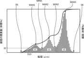
- FIG. 1 is a conceptual diagram of the particle size distribution of a thermally conductive filler.
- the thermally conductive sheet of the present invention has a storage modulus of 0.3 ⁇ 10 9 to 1.2 ⁇ 10 9 Pa and a thermal resistance of 0.07 to 0.12 K/W measured at a tightening torque of 0.5 N ⁇ m, thereby enabling the thermal conductivity and step-following ability of the thermally conductive sheet to be improved.
- the storage modulus of the thermally conductive sheet of the present invention is 0.3 ⁇ 10 9 to 1.2 ⁇ 10 9 Pa. If the storage modulus of the thermally conductive sheet is less than 0.3 ⁇ 10 9 Pa, the thermally conductive sheet may be too soft and the strength of the thermally conductive sheet may be insufficient. If the storage modulus of the thermally conductive sheet is greater than 1.2 ⁇ 10 9 Pa, the interface thermal resistance of the thermally conductive sheet may be high and the thermal conductivity of the thermally conductive sheet may be poor. In addition, if the storage modulus of the thermally conductive sheet is greater than 1.2 ⁇ 10 9 Pa, the flexibility of the thermally conductive sheet may be poor and the step-following ability may be poor.
- the thermal resistance of the thermally conductive sheet of the present invention measured when the tightening torque is 0.5 N ⁇ m is 0.07 to 0.12 K/W. It is difficult to make the thermal resistance of the thermally conductive sheet less than 0.07°C/W (while also achieving insulation). If the thermal resistance of the thermally conductive sheet is greater than 0.12°C/W, the thermal conductive sheet may not be able to meet the increasingly stringent requirements for thermal conductivity due to the recent miniaturization of electronic devices and the increase in the amount of heat generated by heat-generating electronic components. From this perspective, the thermal resistance of the thermally conductive sheet is preferably 0.07 to 0.11°C/W, more preferably 0.07 to 0.10°C/W. The thermal resistance of the thermally conductive sheet can be measured by the method described in the Examples below. The thermal resistance of the thermally conductive sheet can be adjusted by improving the thermal conductivity of the sheet and improving its flexibility.
- the degree of BN orientation in the thermally conductive sheet of the present invention is preferably 6 to 70.
- the degree of BN orientation in the thermally conductive sheet is 6 to 70, it indicates that the direction in which the thermal conductivity of the thermally conductive filler is low is not aligned in the thickness direction of the thermally conductive sheet, and the thermal conductivity of the thermally conductive sheet can be further improved.
- the degree of BN orientation in the thermally conductive sheet of the present invention is more preferably 7 to 60, even more preferably 8 to 50, and even more preferably 10 to 40.
- the degree of BN orientation in the thermally conductive sheet can be measured by the method described in the examples below.
- the degree of BN orientation in the thermally conductive sheet can be adjusted by adjusting the press pressure during sheet preparation to improve the crush strength of the filler used.
- the thermal conductive sheet of the present invention preferably has a breakdown voltage of 15 kV/mm or more. If the breakdown voltage is 15 kV/mm or more, the thermal conductive sheet can meet the increasingly stringent requirements for insulation due to the miniaturization of electronic devices in recent years and the increase in the amount of heat generated by heat-generating electronic components. From this perspective, the breakdown voltage of the thermal conductive sheet is more preferably 20 kV/mm or more, and even more preferably 25 kV/mm or more. The upper limit of the range of the breakdown voltage of the thermal conductive sheet is not particularly limited, but is usually 50 kV/mm. The breakdown voltage of the thermal conductive sheet can be measured by the method described in the examples below. The breakdown voltage of the thermal conductive sheet can also be adjusted by lowering the filler loading amount.
- the thickness of the thermally conductive sheet of the present invention is not particularly limited, but is preferably 0.1 to 1 mm, more preferably 0.15 to 0.9 mm, and even more preferably 0.2 to 0.8 mm.
- the thermally conductive sheet of the present invention preferably contains a thermally conductive filler.
- the thermally conductive filler used in the thermally conductive sheet of the present invention is not particularly limited as long as it is a thermally conductive filler that is usually used in thermally conductive sheets.
- Examples of the thermally conductive filler used in the thermally conductive sheet of the present invention include amorphous granular fillers, spherical fillers, needle-like fillers, fibrous fillers, and plate-like fillers. These heat dissipating fillers can be used alone or in combination of two or more.
- spherical fillers are preferred among these thermally conductive fillers.
- examples of spherical fillers include alumina, silica, calcium carbonate, aluminum nitride, and magnesium oxide.
- spherical aggregated fillers can be obtained by agglomerating the primary particles. These spherical fillers can be used alone or in combination of two or more.
- agglomerated particles formed by agglomeration of primary particles are preferred, and agglomerated boron nitride particles formed by agglomeration of primary particles of boron nitride are more preferred.
- the crushing strength of the aggregated particles formed by agglomeration of primary particles used in the thermal conductive sheet of the present invention is preferably 5 to 15 MPa. If the crushing strength of the aggregated particles formed by agglomeration of primary particles is 5 MPa or more, the aggregated particles will collapse during the production of the thermal conductive sheet, and the degree of BN orientation in the thermal conductive sheet can be suppressed from increasing. If the crushing strength of the aggregated particles formed by agglomeration of primary particles is 15 MPa or less, the voids in the sheet can be reduced by deformation of the aggregated particles, and the thermal conductivity can be further improved.
- the crushing strength of the aggregated particles formed by agglomeration of primary particles is more preferably 6 to 13 MPa, and even more preferably 7 to 11 MPa.
- the crushing strength of the aggregated particles formed by agglomeration of primary particles can be measured by the method described in the Examples below.
- the particle size distribution of the thermally conductive filler is not particularly limited.
- the particle size distribution of the thermally conductive filler used in the thermally conductive sheet of the present invention may have only the first maximum point, or may have only the first maximum point and the second maximum point having a particle size larger than the first maximum point.
- the particle size distribution of the thermally conductive filler used in the thermally conductive sheet of the present invention preferably has at least the first maximum point (MAX1), the second maximum point (MAX2) having a particle size larger than the first maximum point (MAX1), and the third maximum point (MAX3) having a particle size larger than the second maximum point (MAX2).
- the particle size of the first maximum point (MAX1) is 0.4 ⁇ m or more and less than 10 ⁇ m
- the particle size of the second maximum point (MAX2) is 10 ⁇ m or more and less than 40 ⁇ m
- the particle size of the third maximum point (MAX3) is 40 ⁇ m or more and 110 ⁇ m or less.
- the particle size at the first maximum point (MAX1) is preferably 0.4 ⁇ m or more and less than 10 ⁇ m. If the particle size at the first maximum point (MAX1) is 0.4 ⁇ m or more and less than 10 ⁇ m, the filling property of the thermally conductive filler in the thermally conductive sheet can be further increased, and the thermal conductivity of the thermally conductive sheet can be further improved. From this perspective, the particle size at the first maximum point (MAX1) is more preferably 1.0 to 9.0 ⁇ m, and even more preferably 2.0 to 8.0 ⁇ m.
- the particle size at the second maximum point (MAX2) is preferably 10 ⁇ m or more and less than 40 ⁇ m. If the particle size at the second maximum point (MAX2) is 10 ⁇ m or more and less than 40 ⁇ m, the filling property of the thermally conductive filler in the thermally conductive sheet can be further increased, and the thermal conductivity of the thermally conductive sheet can be further improved. From this perspective, the particle size at the second maximum point (MAX2) is more preferably 15 to 36 ⁇ m, and even more preferably 18 to 30 ⁇ m.
- the particle size at the third maximum point (MAX3) is preferably 40 to 110 ⁇ m. If the particle size at the third maximum point (MAX3) is 40 to 110 ⁇ m, the filling of the thermally conductive filler in the thermally conductive sheet can be further increased, and the thermal conductivity of the thermally conductive sheet can be further improved. From this perspective, the particle size at the third maximum point (MAX3) is more preferably 50 to 100 ⁇ m, and even more preferably 65 to 90 ⁇ m.
- the cumulative amount (V1) of the frequency between the peak start and the peak end in the peak having the first maximum point (MAX1) is preferably 1 to 27% by volume.
- the cumulative amount (V1) is 1 to 27% by volume, the filling of the thermally conductive filler in the thermally conductive sheet can be further increased, and the thermal conductivity of the thermally conductive sheet can be further improved. From this viewpoint, the cumulative amount (V1) is more preferably 5 to 20% by volume.
- the peak start in the peak having the first maximum point (MAX1) is a minimum point on the side of the smaller particle size relative to the first maximum point (MAX1).
- the peak start is the end (DS) of the particle size distribution on the side of the smaller particle size.
- the peak end in the peak having the first maximum point (MAX1) is a minimum point (MIN1) on the side of the larger particle size relative to the first maximum point (MAX1).
- the cumulative amount of frequency (V1) is the value obtained by subtracting the frequency of the particle size of the minimum point (MIN1) on the larger particle size side of the first maximum point (MAX1) from the cumulative amount of frequency from the particle size of the minimum point on the smaller particle size side of the first maximum point (MAX1) or the particle size of the end (DS) of the particle size distribution on the smaller particle size side of the first maximum point (MAX1).
- the reason for subtracting the frequency of the particle size of the minimum point (MIN1) on the larger particle size side of the first maximum point (MAX1) is to prevent the frequency of the particle size of the minimum point (MIN1) on the larger particle size side of the first maximum point (MAX1) from being added to both the cumulative amount of frequency between the peak start and the peak end of the peak having the first maximum point (MAX1) and the cumulative amount of frequency between the peak start and the peak end of the peak having the second maximum point (MAX2).
- the cumulative amount (V2) of the frequency between the peak start and the peak end in the peak having the second maximum point (MAX2) is preferably 5 to 40 volume %.
- the cumulative amount (V2) is 5 to 40 volume %, the filling of the thermally conductive filler in the thermally conductive sheet can be further increased, and the thermal conductivity of the thermally conductive sheet can be further improved. From this viewpoint, the cumulative amount (V2) is more preferably 10 to 30 volume %.
- the peak start in the peak having the second maximum point (MAX2) is the minimum point (MIN1) on the side of the smaller particle size relative to the second maximum point (MAX2).
- the peak end in the peak having the second maximum point (MAX2) is the minimum point (MIN2) on the side of the larger particle size relative to the second maximum point (MAX2).
- the cumulative amount of frequency (V2) is the value obtained by subtracting the frequency of the particle size of the minimum point (MIN2) on the larger particle size side of the second maximum point (MAX2) from the cumulative amount of frequency from the particle size of the minimum point (MIN1) on the smaller particle size side of the second maximum point (MAX2) to the particle size of the minimum point (MIN2) on the larger particle size side of the second maximum point (MAX2).
- the reason for subtracting the frequency of the particle size of the minimum point (MIN2) on the larger particle size side of the second maximum point (MAX2) is to prevent the frequency of the particle size of the minimum point (MIN2) on the larger particle size side of the second maximum point (MAX2) from being added to both the cumulative amount of frequency between the peak start and the peak end of the peak having the second maximum point (MAX2) and the cumulative amount of frequency between the peak start and the peak end of the peak having the third maximum point (MAX3).
- the cumulative amount (V3) of the frequency between the peak start and the peak end in the peak having the third maximum point (MAX3) is preferably 50 to 90 volume %. If the cumulative amount (V3) is 50 to 90 volume %, the filling of the thermally conductive filler in the thermally conductive sheet can be further increased, and the thermal conductivity of the thermally conductive sheet can be further improved. From this viewpoint, the cumulative amount (V3) is more preferably 60 to 80 volume %.
- the peak start in the peak having the third maximum point (MAX3) is the minimum point (MIN2) on the side of the smaller particle size relative to the third maximum point (MAX3).
- the peak end in the peak having the third maximum point (MAX3) is the minimum point on the side of the larger particle size relative to the third maximum point (MAX3). If there is no minimum point on the side of the larger particle size relative to the third maximum point (MAX3), the peak end is the end (DE) on the larger particle size side of the particle size distribution.
- the integrated amount of frequency (V3) is the value obtained by subtracting the frequency of the particle size of the minimum point on the larger particle size side than the third maximum point (MAX3) from the integrated amount of frequency from the particle size of the minimum point (MIN2) on the smaller particle size side than the third maximum point (MAX3) to the particle size of the minimum point on the larger particle size side than the third maximum point (MAX3), or the integrated amount of frequency from the particle size of the minimum point (MIN2) on the smaller particle size side than the third maximum point (MAX3) to the particle size at the larger particle size end (DE) of the particle size distribution.
- the frequency of particle sizes of the minimum points on the larger particle size side of the third maximum point (MAX3) is subtracted to prevent the frequency of particle sizes of the minimum points on the larger particle size side of the third maximum point (MAX3) from being added to both the integrated amount of frequency between the peak start and the peak end of a peak having the third maximum point (MAX3) and the integrated amount of frequency between the peak start and the peak end of a peak having a maximum point adjacent to the third maximum point (MAX3) and on the larger particle size side of the third maximum point.
- the particle size distribution of the thermally conductive filler used in the thermally conductive sheet of the present invention may have other maximum points in addition to the first to third maximum points described above.
- the boron nitride particles used in the thermally conductive sheet of the present invention can be produced, for example, by preparing a first thermally conductive filler having a particle size distribution with the above-mentioned first maximum point, a second thermally conductive filler having a particle size distribution with the above-mentioned second maximum point, and a third thermally conductive filler having a particle size distribution with the above-mentioned third maximum point, and mixing the first to third thermally conductive fillers thus prepared.
- the second and third thermally conductive fillers each preferably contain at least aggregate boron nitride particles.
- the first thermally conductive filler may be aggregate boron nitride particles, but is preferably hexagonal boron nitride primary particles.
- the maximum points of the first to third thermally conductive fillers each mean the apex of the peak in the particle size distribution of the first to third thermally conductive fillers.
- the particle size distribution of the first to third thermally conductive fillers is measured in the same manner as the particle size distribution of the thermally conductive fillers described above.
- the first to third thermally conductive fillers may be mixed so that the volumetric ratio of the third thermally conductive filler is greater than the volumetric ratio of the first thermally conductive filler and the volumetric ratio of the second thermally conductive filler. This can further increase the filling property of the thermally conductive filler.
- the volumetric ratio of the third thermally conductive filler is preferably 50 to 90 parts by volume, more preferably 60 to 80 parts by volume, relative to a total of 100 parts by volume of the first to third thermally conductive fillers.
- the volumetric ratio of the second thermally conductive filler is preferably 5 to 40 parts by volume, more preferably 10 to 30 parts by volume, relative to a total of 100 parts by volume of the first to third thermally conductive fillers.
- the volume ratio of the first thermally conductive filler is preferably 1 to 27 parts by volume, and more preferably 5 to 20 parts by volume, per 100 parts by volume of the first to third thermally conductive fillers combined.
- Each of the aggregate boron nitride particles used as the thermally conductive filler can be produced, for example, by a production method including a grinding process for grinding aggregate boron carbide, a nitriding process for nitriding the ground boron carbide to obtain boron carbonitride, and a decarburization process for decarbonizing the boron carbonitride.
- the boron carbide lumps (boron carbide lumps) are ground using a general grinding or crushing machine. At this time, for example, by adjusting the grinding time and the amount of boron carbide lumps charged, it is possible to obtain boron carbide powder having a desired maximum point.
- the maximum point of the boron carbide powder can be measured in the same manner as the maximum point of the boron nitride particles described above. In this way, by adjusting the maximum point of the boron carbide powder to approach the maximum point of the desired boron nitride particles, the first to third boron nitride particles having the above-mentioned maximum points can be obtained.
- the boron carbide powder is sintered under pressure in an atmosphere that promotes the nitriding reaction to obtain boron carbonitride.
- the atmosphere in the nitriding step is an atmosphere that allows the nitriding reaction to proceed, and may be, for example, nitrogen gas or ammonia gas, or the like, which may be one kind alone or a combination of two or more kinds. From the viewpoint of ease of nitriding and cost, the atmosphere is preferably nitrogen gas.
- the content of nitrogen gas in the atmosphere is preferably 95% by volume or more, and more preferably 99.9% by volume or more.
- the pressure in the nitriding step is preferably 0.6 MPa or more, more preferably 0.7 MPa or more, and preferably 1.0 MPa or less, more preferably 0.9 MPa or less.
- the pressure is further preferably 0.7 to 1.0 MPa.
- the firing temperature in the nitriding step is preferably 1800°C or more, more preferably 1900°C or more, and preferably 2400°C or less, more preferably 2200°C or less.
- the firing temperature is further preferably 1800 to 2200°C.
- the pressure conditions and firing temperature are preferably 1800°C or more and 0.7 to 1.0 MPa, as these conditions further facilitate the nitridation of boron carbide and are also industrially appropriate.
- the firing time in the nitriding step is appropriately selected within a range in which nitriding proceeds sufficiently, and is preferably 6 hours or more, more preferably 8 hours or more, and is preferably 30 hours or less, more preferably 20 hours or less.
- the boron carbonitride obtained in the nitridation process is subjected to a heat treatment in an atmosphere above normal pressure, where it is held at a predetermined holding temperature for a certain period of time.
- the atmosphere in the decarburization process is either a normal pressure (atmospheric pressure) atmosphere or a pressurized atmosphere.
- the pressure may be, for example, 0.5 MPa or less, preferably 0.3 MPa or less.
- the temperature is first raised to a predetermined temperature (the temperature at which decarburization can begin), and then further raised to the holding temperature at a predetermined heating rate.
- the predetermined temperature (the temperature at which decarburization can begin) can be set according to the system, and may be, for example, 1000°C or higher, 1500°C or lower, and preferably 1200°C or lower.
- the rate at which the temperature is raised from the predetermined temperature (the temperature at which decarburization can begin) to the holding temperature may be, for example, 5°C/min or lower, and preferably 4°C/min or lower, 3°C/min or lower, or 2°C/min or lower.
- the holding time at the holding temperature is appropriately selected within a range in which crystallization proceeds sufficiently, and may be, for example, more than 0.5 hours. From the viewpoint of favorable grain growth, it is preferably 1 hour or more, more preferably 3 hours or more, even more preferably 5 hours or more, and particularly preferably 10 hours or more.
- the holding time at the holding temperature may be, for example, less than 40 hours, and from the viewpoint of reducing costs and reducing the decrease in particle strength due to excessive grain growth, it is preferably 30 hours or less, more preferably 20 hours or less.
- the mixing ratio of boron carbonitride and the boron source is appropriately selected.
- the ratio of boric acid or boron oxide may be, for example, 100 parts by mass or more, preferably 150 parts by mass or more, and may be, for example, 300 parts by mass or less, preferably 250 parts by mass or less, per 100 parts by mass of boron carbonitride.
- the boron nitride particles obtained as described above may be subjected to a classification step (classification step) using a sieve to obtain boron nitride particles having a desired particle size distribution. This makes it possible to obtain the first to third aggregate boron nitride particles that can be used as the first to third thermally conductive fillers.
- the thermally conductive sheet of the present invention preferably contains a resin.
- the resin contained in the thermally conductive sheet is not particularly limited, but examples thereof include thermosetting resins such as silicone resin, epoxy resin, phenol resin, cyanate resin, melamine resin, urea resin, thermosetting polyimide, and unsaturated polyester resin; and thermoplastic resins such as acrylic resin, polyolefin resin, polycarbonate resin, polyester resin, vinyl chloride resin, urethane resin, polyamide resin, and ABS (acrylonitrile-butadiene-styrene) resin.
- thermosetting resins such as silicone resin, epoxy resin, phenol resin, cyanate resin, melamine resin, urea resin, thermosetting polyimide, and unsaturated polyester resin
- thermoplastic resins such as acrylic resin, polyolefin resin, polycarbonate resin, polyester resin, vinyl chloride resin, urethane resin, polyamide resin, and ABS (acrylonitrile-butadiene-styrene) resin.
- the thermally conductive sheet of the present invention contains a silicone resin
- the thermally conductive sheet of the present invention contains unreacted silicone oil in addition to the silicone resin, thereby improving the flexibility of the thermally conductive sheet. As a result, the interface thermal resistance of the thermally conductive sheet is further reduced, and the thermal conductivity of the thermally conductive sheet can be further improved, and the step-following ability can also be further improved.
- silicone polymer examples include methyl vinyl-based silicone polymers, methyl phenyl vinyl-based silicone polymers, and methyl fluoroalkyl-based silicone polymers.
- the silicone resin may contain additives such as silica fillers and dispersants.
- the content of the radically cured silicone resin in the silicone resin is preferably 80 to 100% by volume, more preferably 90 to 100% by volume, and even more preferably 95 to 100% by volume.
- the kinetic viscosity of the unreacted silicone oil is preferably m 2 /s or less, more preferably 1 m 2 /s or less, and even more preferably 0.5 m 2 /s or less.
- the kinetic viscosity of the unreacted silicone oil can be measured by the method described in the examples below.
- the mass average molecular weight of the silicone resin used in the thermally conductive sheet of the present invention is preferably 30,000 to 1,000,000, more preferably 40,000 to 800,000, and even more preferably 50,000 to 600,000.
- the mass average molecular weight of the unreacted silicone oil is preferably 50,000 to 1,500,000, more preferably 60,000 to 1,200,000, and even more preferably 70,000 to 1,000,000.
- the mass average molecular weights of the silicone resin and the unreacted silicone oil can be measured using gel permeation chromatography.
- the content of the thermally conductive filler in the thermally conductive sheet of the present invention is preferably 20 to 90 vol%, more preferably 25 to 85 vol%, based on the total 100 vol% of the thermally conductive filler and resin, or, when unreacted silicone oil is included, based on the total 100 vol% of the thermally conductive filler, silicone resin, and unreacted silicone oil.
- the content of the thermally conductive filler is 20 vol% or more, the thermal conductivity of the thermally conductive sheet tends to be further improved.
- the content of the thermally conductive filler is 90 vol% or less, the dispersibility of the thermally conductive filler in the thermally conductive sheet is improved.
- the content of the unreacted silicone oil in the thermally conductive sheet of the present invention is preferably 1 to 15% by mass.
- the content of the unreacted silicone oil in the thermally conductive sheet is 1% by mass or more, the flexibility of the thermally conductive sheet can be further improved, and the storage modulus and thermal resistance of the thermally conductive sheet can be further reduced.
- the content of the unreacted silicone oil in the thermally conductive sheet is 15% by mass or less, the exudation of the unreacted silicone oil from the thermally conductive sheet can be suppressed.
- the content of the unreacted silicone oil in the thermally conductive sheet of the present invention is more preferably 2 to 12% by mass, and even more preferably 5 to 8% by mass.
- the content of unreacted silicone oil in the thermally conductive sheet can be measured, for example, as follows.
- the initial mass of a 50 mm x 50 mm thermally conductive heat dissipation sheet was measured (A), and the sheet was immersed in toluene 250 times the initial mass at room temperature for 24 hours.
- the sample was removed after immersion and dried in a dryer at 130°C for 2 hours to remove the toluene, and the dry mass (B) was measured.
- the thermally conductive sheet of the present invention contains a silicone resin and an unreacted silicone oil
- the ratio of the content (volume %) of the unreacted silicone oil to the total content (volume %) of the silicone resin content (volume %) and the content (volume %) of the unreacted silicone oil in the thermally conductive sheet is preferably 5 to 55%.
- the content of the unreacted silicone oil is 5% or more, the flexibility of the thermally conductive sheet can be further improved, and the storage modulus and thermal resistance of the thermally conductive sheet can be further reduced.
- the content of the unreacted silicone oil is 55% or less, insufficient curing of the thermally conductive sheet can be suppressed. From this viewpoint, the content of the unreacted silicone oil is more preferably 7 to 40%, and even more preferably 10 to 30%.
- the thermally conductive sheet of the present invention can be produced, for example, by a production method including a step (A) of blending a thermally conductive filler, a silicone resin, and an unreacted silicone oil to prepare a thermally conductive resin composition, a step (B) of forming the thermally conductive resin composition into a sheet to prepare a thermally conductive resin composition sheet, and a step (C) of heating and pressurizing the thermally conductive resin composition sheet.
- a thermally conductive resin composition is prepared by blending a thermally conductive filler, a silicone resin, and an unreacted silicone oil.
- the thermally conductive filler, the silicone resin, and the unreacted silicone oil used in step (A) have already been described, and therefore will not be described here.
- step (B) the thermally conductive resin composition is molded into a sheet to produce a thermally conductive resin composition sheet.
- the thermally conductive resin composition can be molded into a sheet by a doctor blade method or a calendar process.
- the thermally conductive filler is an aggregated particle
- the aggregated particle in the thermally conductive resin composition may collapse when the thermally conductive resin composition passes through a calendar roll. Therefore, it is preferable to mold the thermally conductive resin composition into a sheet by a doctor blade method.
- step (C) the thermally conductive resin composition sheet is heated and pressurized. This can further increase the filling of the thermally conductive filler in the thermally conductive sheet, and can further improve the thermal conductivity of the thermally conductive sheet.
- the heating temperature of the thermally conductive resin composition sheet is preferably 120 to 200°C, more preferably 130 to 180°C.
- the pressure when pressing the thermally conductive resin composition sheet is preferably 1 to 25 MPa, more preferably 5 to 20 MPa.
- step (C) a laminate of the thermally conductive resin composition sheet and the glass cloth may be prepared, and the laminate may be heated and pressurized under vacuum. This allows the production of a thermally conductive sheet including the glass cloth.
- boron nitride particles were used as the thermally conductive filler.
- Three types of raw boron nitride particles having a maximum point of a given particle size were mixed to produce boron nitride particles having three maximum points.
- the raw boron nitride particles used as the raw material of the boron nitride particles used in the thermally conductive sheets of the examples and comparative examples were evaluated as follows. (Average particle size) The average particle size of the raw material boron nitride particles was measured using a Beckman Coulter laser diffraction scattering particle size distribution analyzer (LS-13 320). The average particle size obtained was measured without using a homogenizer before the measurement process and used as the average particle size value. The average particle size obtained is the average particle size based on volume statistics.
- the boron nitride particles produced by mixing the three types of raw material boron nitride particles were subjected to the following evaluations.
- the crushing strength of the boron nitride particles was measured in accordance with JIS R1639-5:2007. Specifically, after the boron nitride particles were spread on the sample stage of a microcompression tester ("MCT-211" manufactured by Shimadzu Corporation), 20 aggregated boron nitride particles were selected from the boron nitride particles, and a compression test was carried out on each particle.
- the crushing strengths of 20 inorganic filler components were Weibull plotted in accordance with JIS R1625:2010, and the crushing strength at which the cumulative destruction rate was 63.2% was determined as the crushing strength of the boron nitride particles.
- the particle size distribution of the boron nitride particles was measured using a laser diffraction scattering particle size distribution analyzer (LS-13 320) manufactured by Beckman Coulter Inc. Prior to measuring the particle size distribution, the boron nitride particles were not dispersed using a homogenizer or the like.
- Unreacted silicone oil was used in the preparation of the thermally conductive sheets of the Examples and Comparative Examples.
- the unreacted silicone oil used in the thermally conductive sheets of the Examples and Comparative Examples was evaluated as follows. (Kinematic Viscosity) The kinetic viscosity of the unreacted silicone oil at 25°C was measured in accordance with the method described in JIS Z 8803:2011.
- the thermally conductive sheets of the examples and comparative examples were evaluated as follows.
- Storage Modulus A dynamic viscoelasticity measuring device (Hitachi High-Tech Science, DMA7100) was used to measure at a frequency of 1 Hz and in the temperature range of 0° C. to +200° C. Measurement samples (7 mm ⁇ 40 mm) were cut out from films with a thickness of about 0.1 to 0.3 mm and measured to determine the storage modulus at 50° C. The main measurement parameters involved in the measurement are as follows: Measurement frequency: 1Hz Heating rate: 5°C/min. Sample measurement length: 20 mm. Distortion: 0.1%.
- BN orientation in sheet The degree of BN orientation in the sheet was measured using an X-ray diffractometer (ULTIMA-IV manufactured by Rigaku Corporation). A sample was cut to a size of 1.5 cm x 1.5 cm, and the sample was irradiated with X-rays to calculate and evaluate the peak intensity ratio (002)/(100) of the (002) plane and the (100) plane.
- the dielectric breakdown voltage of the thermal conductive sheet was measured in a short-time breakdown test (room temperature 23° C.) in accordance with JIS C 2110, and the evaluation criteria for the insulation were calculated as follows: ⁇ : Dielectric breakdown voltage is 20 kV/mm or more. ⁇ : Dielectric breakdown voltage is 10 kV/mm or more and less than 20 kV/mm. ⁇ : Dielectric breakdown voltage is less than 10 kV/mm.
- Thermal conductivity The thermal conductivity of the thermally conductive sheet was measured in accordance with the method described in ASTM D5470:2017.
- the evaluation criteria for thermal conductivity are as follows: ⁇ : Thermal conductivity is 5 W/(m.K) or more. ⁇ : Thermal conductivity is 3 W/(m.K) or more, but less than 5 W/(m.K). ⁇ : Thermal conductivity is less than 3 W/(m.K).
- Step-following ability A thermally conductive sheet cut to a length of 20 cm and a width of 5 cm was placed across two glass plates with a height of 0.5 cm. The distance between the two glass plates was gradually increased, and the length between the glass plates was measured when the thermally conductive sheet was placed on the desk.
- the evaluation criteria for the step-following ability are as follows. ⁇ : Distance between glass plates is less than 8 cm. ⁇ : Distance between glass plates is 8 cm or more but less than 10 cm. ⁇ : Distance between glass plates is 10 cm or more.
- Silicone resin silicone resin containing vinyl groups at both ends: product name "CF-3110" manufactured by Dow-Toray Industries, Inc.
- Unreacted Silicone Oil Unreacted Silicone Oil 1: Dimethyl silicone oil, manufactured by Wacker Asahi Kasei Co., Ltd., product name "SILICONE FLUID AK1000000", kinetic viscosity 1 m 2 /s (1 million cSt)
- Unreacted silicone oil 2 dimethyl silicone oil, manufactured by Wacker Asahi Kasei Co., Ltd., product name "SILICONE FLUID AK100000", kinetic viscosity 0.1 m 2 /s (100,000 cSt)
- Boron nitride particles A were produced by the following steps: synthesis of boron carbide, pressure nitridation process, and decarburization crystallization process.
- Boric acid orthoboric acid
- HS100 acetylene black
- the synthesized boron carbide block was pulverized in a ball mill for 3 hours, sieved using a sieve to particle sizes of 75 ⁇ m or less, further washed with an aqueous nitric acid solution to remove impurities such as iron, and then filtered and dried to produce boron carbide powder with an average particle size of 55 ⁇ m.
- the synthesized aggregated boron nitride particles were decomposed and crushed 15 times using a Henschel mixer, and then classified using a nylon sieve with a mesh size of 150 ⁇ m using a sieve net. Boron nitride particles A were obtained by crushing and classifying the fired product.
- the average particle diameter (D50) of the obtained boron nitride particles A measured by the laser scattering method was 70 ⁇ m. SEM observation revealed that the obtained boron nitride particles A were aggregated boron nitride particles formed by the aggregation of primary particles. The crushing strength of the obtained boron nitride particles A was 9 MPa.
- B Boric acid, melamine, and calcium carbonate (all special grade reagents) were mixed in a mass ratio of 70:50:5, and in a nitrogen gas atmosphere, the temperature was raised from room temperature to 1400°C in 1 hour, held at 1400°C for 3 hours, then raised to 1900°C in 4 hours, held at 1900°C for 2 hours, and then cooled to room temperature to produce hexagonal boron nitride. The mixture was crushed, pulverized, and sieved to prepare boron nitride particles B. The average particle diameter (D50) of the boron nitride particles B measured by a laser scattering method was 70 ⁇ m. As a result of SEM observation, the boron nitride particles B were aggregated boron nitride particles formed by aggregation of primary particles. The crushing strength of the boron nitride particles B was 2 MPa.
- Boron nitride particles C Boron nitride particles C were produced in the same manner as boron nitride particles A, except that boron carbide powder with an average particle size of 10 ⁇ m was used.
- the average particle size (D50) of the obtained boron nitride particles C measured by a laser scattering method was 20 ⁇ m.
- the obtained boron nitride particles C were aggregated boron nitride particles formed by aggregation of primary particles.
- the crushing strength of the obtained boron nitride particles C was 8 MPa.
- Boron nitride particles D Boric acid, melamine, and calcium carbonate (all special grade reagents) were mixed in a mass ratio of 70:50:5, and in a nitrogen gas atmosphere, the temperature was raised from room temperature to 1400°C in 1 hour, held at 1400°C for 3 hours, then raised to 1900°C in 4 hours, held at 1900°C for 2 hours, and then cooled to room temperature to produce hexagonal boron nitride. The mixture was crushed, pulverized, and sieved to prepare boron nitride particles D. The average particle diameter (D50) of the boron nitride particles D measured by a laser scattering method was 20 ⁇ m. As a result of SEM observation, the boron nitride particles D were aggregated boron nitride particles formed by aggregation of primary particles. The crushing strength of the boron nitride particles D was 1.5 MPa.
- boron nitride particles E Commercially available boron nitride particles (manufactured by Denka Co., Ltd., product name "HGP") were used as the boron nitride particles E.
- the boron nitride particles E were scaly primary particles.
- Boron nitride particles 1 and 2 were prepared as follows. [Boron nitride particles 1] Boron nitride particles A, C, and E were mixed so that the volume ratio of the boron nitride particles A, C, and E was 70:15:15, to prepare boron nitride particles 1.
- a thermally conductive sheet was prepared as follows. [Preparation of Thermally Conductive Sheet 1] The boron nitride particles 1, silicone resin, and unreacted silicone oil were weighed out so that the ratio of the boron nitride particles 1 was 55 parts by volume, the ratio of the silicone resin was 40.5 parts by volume, and the ratio of the unreacted silicone oil 1 was 4.5 parts by volume, and were put into a mixer (product name: Three-One Motor, manufactured by HEIDON Co., Ltd.).
- a curing agent (2,5-dimethyl-2,5-bis(t-butylperoxy)hexane, manufactured by Kayaku Nouryon Co., Ltd., product name "Trigonox 101"
- a silane coupling agent dimethyldimethoxysilane, manufactured by Dow Toray Co., Ltd., product name "DOWSIL Z-6329 Silane", viscosity at 25 ° C.: 1 cp
- 15 parts by mass of water per 100 parts by mass of the silane coupling agent were put in.
- the layer structure of this laminate was PET film / thermally conductive resin composition / glass cloth / thermally conductive resin composition / PET film.
- the obtained laminate was subjected to a heat press for 30 minutes under conditions of a vacuum (pressure 3.5 kPa), a temperature of 150 ° C, and a pressure of 15 MPa, and the PET films on both sides were peeled off to obtain a sheet having a thickness of 0.2 mm.
- a vacuum pressure 3.5 kPa
- a temperature of 150 ° C a temperature of 150 ° C
- a pressure of 15 MPa a pressure of 15 MPa
- Thermally conductive sheets 2 to 23 were produced in the same manner as thermally conductive sheet 1, except that the type and amount of boron nitride particles, the amount of silicone resin, and the type and amount of unreacted silicone oil were changed as shown in Table 1.
- the coating thickness of the samples with different thicknesses was set to 0.3 mm.
- thermally conductive sheet with high thermal conductivity and excellent step-following ability can be obtained by setting the storage modulus of the thermally conductive sheet to 0.3 x 10 9 to 1.2 x 10 9 Pa and the thermal resistance measured at a tightening torque of 0.5 N ⁇ m to 0.07 to 0.12 K/W.
Landscapes
- Chemical & Material Sciences (AREA)
- Organic Chemistry (AREA)
- Inorganic Chemistry (AREA)
- Chemical Kinetics & Catalysis (AREA)
- Engineering & Computer Science (AREA)
- Combustion & Propulsion (AREA)
- Physics & Mathematics (AREA)
- Thermal Sciences (AREA)
- Materials Engineering (AREA)
- Health & Medical Sciences (AREA)
- Medicinal Chemistry (AREA)
- Polymers & Plastics (AREA)
- Cooling Or The Like Of Semiconductors Or Solid State Devices (AREA)
- Manufacture Of Macromolecular Shaped Articles (AREA)
- Compositions Of Macromolecular Compounds (AREA)
Priority Applications (3)
| Application Number | Priority Date | Filing Date | Title |
|---|---|---|---|
| EP24779658.4A EP4657519A4 (en) | 2023-03-27 | 2024-03-18 | HEAT-CONDUCTING SHEET |
| JP2025510535A JPWO2024203533A1 (cg-RX-API-DMAC7.html) | 2023-03-27 | 2024-03-18 | |
| CN202480015675.5A CN120883362A (zh) | 2023-03-27 | 2024-03-18 | 导热性片材 |
Applications Claiming Priority (2)
| Application Number | Priority Date | Filing Date | Title |
|---|---|---|---|
| JP2023-049554 | 2023-03-27 | ||
| JP2023049554 | 2023-03-27 |
Publications (1)
| Publication Number | Publication Date |
|---|---|
| WO2024203533A1 true WO2024203533A1 (ja) | 2024-10-03 |
Family
ID=92904697
Family Applications (1)
| Application Number | Title | Priority Date | Filing Date |
|---|---|---|---|
| PCT/JP2024/010529 Ceased WO2024203533A1 (ja) | 2023-03-27 | 2024-03-18 | 熱伝導性シート |
Country Status (4)
| Country | Link |
|---|---|
| EP (1) | EP4657519A4 (cg-RX-API-DMAC7.html) |
| JP (1) | JPWO2024203533A1 (cg-RX-API-DMAC7.html) |
| CN (1) | CN120883362A (cg-RX-API-DMAC7.html) |
| WO (1) | WO2024203533A1 (cg-RX-API-DMAC7.html) |
Citations (2)
| Publication number | Priority date | Publication date | Assignee | Title |
|---|---|---|---|---|
| WO2019189626A1 (ja) * | 2018-03-30 | 2019-10-03 | バンドー化学株式会社 | 熱伝導性シート、熱伝導性シートの製造方法、及び、熱伝導性シートの使用方法 |
| WO2022149435A1 (ja) * | 2021-01-06 | 2022-07-14 | デンカ株式会社 | 窒化ホウ素粉末、放熱シート及び放熱シートの製造方法 |
Family Cites Families (1)
| Publication number | Priority date | Publication date | Assignee | Title |
|---|---|---|---|---|
| JP7273587B2 (ja) | 2019-03-29 | 2023-05-15 | デンカ株式会社 | 窒化ホウ素粉末及び樹脂組成物 |
-
2024
- 2024-03-18 JP JP2025510535A patent/JPWO2024203533A1/ja active Pending
- 2024-03-18 WO PCT/JP2024/010529 patent/WO2024203533A1/ja not_active Ceased
- 2024-03-18 EP EP24779658.4A patent/EP4657519A4/en active Pending
- 2024-03-18 CN CN202480015675.5A patent/CN120883362A/zh active Pending
Patent Citations (2)
| Publication number | Priority date | Publication date | Assignee | Title |
|---|---|---|---|---|
| WO2019189626A1 (ja) * | 2018-03-30 | 2019-10-03 | バンドー化学株式会社 | 熱伝導性シート、熱伝導性シートの製造方法、及び、熱伝導性シートの使用方法 |
| WO2022149435A1 (ja) * | 2021-01-06 | 2022-07-14 | デンカ株式会社 | 窒化ホウ素粉末、放熱シート及び放熱シートの製造方法 |
Non-Patent Citations (1)
| Title |
|---|
| See also references of EP4657519A1 * |
Also Published As
| Publication number | Publication date |
|---|---|
| CN120883362A (zh) | 2025-10-31 |
| EP4657519A1 (en) | 2025-12-03 |
| EP4657519A4 (en) | 2026-05-27 |
| JPWO2024203533A1 (cg-RX-API-DMAC7.html) | 2024-10-03 |
Similar Documents
| Publication | Publication Date | Title |
|---|---|---|
| TWI700243B (zh) | 六方晶氮化硼粉末及其製造方法以及使用其之組成物及散熱材 | |
| TWI598291B (zh) | Hexagonal boron nitride powder, a method for producing the same, a resin composition and a resin sheet | |
| JP7145315B2 (ja) | 塊状窒化ホウ素粒子、熱伝導樹脂組成物及び放熱部材 | |
| JP7362839B2 (ja) | 凝集窒化ホウ素粒子、窒化ホウ素粉末、熱伝導性樹脂組成物及び放熱シート | |
| JP7541090B2 (ja) | 熱伝導性樹脂組成物及び放熱シート | |
| JPWO2020175377A1 (ja) | 窒化ホウ素凝集粉末、放熱シート及び半導体デバイス | |
| JP7580273B2 (ja) | 窒化ホウ素粉末、熱伝導性樹脂組成物、放熱シート及び電子部品構造体 | |
| JP2020164365A (ja) | 窒化ホウ素粉末及び樹脂組成物 | |
| JP7291304B2 (ja) | 窒化ホウ素粉末、放熱シート及び放熱シートの製造方法 | |
| WO2021187609A1 (ja) | 放熱シートおよび放熱シートの製造方法 | |
| JP7629012B2 (ja) | 放熱シート | |
| JP7692267B2 (ja) | 放熱シート及び放熱シートの製造方法 | |
| WO2024203513A1 (ja) | 熱伝導性シート及び凝集窒化ホウ素粒子 | |
| JP7124249B1 (ja) | 放熱シート及び放熱シートの製造方法 | |
| WO2024203519A1 (ja) | 熱伝導性シートの製造方法 | |
| WO2024203527A1 (ja) | 熱伝導性シートの製造方法 | |
| EP4657519A1 (en) | Thermally conductive sheet | |
| JP7692266B2 (ja) | 放熱シート及び放熱シートの製造方法 | |
| JP7293522B1 (ja) | 放熱シート | |
| JP7389939B2 (ja) | 窒化ホウ素粉末 | |
| JP7804810B1 (ja) | 窒化ホウ素粉末、無機フィラー及び窒化ホウ素粉末の製造方法 | |
| JP7796274B1 (ja) | 窒化ホウ素粉末、及び無機フィラー | |
| JP7438442B1 (ja) | 窒化ホウ素凝集粒子、シート部材および窒化ホウ素凝集粒子の製造方法 |
Legal Events
| Date | Code | Title | Description |
|---|---|---|---|
| 121 | Ep: the epo has been informed by wipo that ep was designated in this application |
Ref document number: 24779658 Country of ref document: EP Kind code of ref document: A1 |
|
| ENP | Entry into the national phase |
Ref document number: 2025510535 Country of ref document: JP Kind code of ref document: A |
|
| WWE | Wipo information: entry into national phase |
Ref document number: 2025510535 Country of ref document: JP |
|
| WWE | Wipo information: entry into national phase |
Ref document number: 202480015675.5 Country of ref document: CN |
|
| NENP | Non-entry into the national phase |
Ref country code: DE |
|
| WWP | Wipo information: published in national office |
Ref document number: 202480015675.5 Country of ref document: CN |
|
| WWP | Wipo information: published in national office |
Ref document number: 2024779658 Country of ref document: EP |