WO2024202934A1 - ダンプトラック - Google Patents
ダンプトラック Download PDFInfo
- Publication number
- WO2024202934A1 WO2024202934A1 PCT/JP2024/007804 JP2024007804W WO2024202934A1 WO 2024202934 A1 WO2024202934 A1 WO 2024202934A1 JP 2024007804 W JP2024007804 W JP 2024007804W WO 2024202934 A1 WO2024202934 A1 WO 2024202934A1
- Authority
- WO
- WIPO (PCT)
- Prior art keywords
- power
- battery
- control device
- vehicle control
- dump truck
- Prior art date
- Legal status (The legal status is an assumption and is not a legal conclusion. Google has not performed a legal analysis and makes no representation as to the accuracy of the status listed.)
- Ceased
Links
Images




Classifications
-
- B—PERFORMING OPERATIONS; TRANSPORTING
- B60—VEHICLES IN GENERAL
- B60L—PROPULSION OF ELECTRICALLY-PROPELLED VEHICLES; SUPPLYING ELECTRIC POWER FOR AUXILIARY EQUIPMENT OF ELECTRICALLY-PROPELLED VEHICLES; ELECTRODYNAMIC BRAKE SYSTEMS FOR VEHICLES IN GENERAL; MAGNETIC SUSPENSION OR LEVITATION FOR VEHICLES; MONITORING OPERATING VARIABLES OF ELECTRICALLY-PROPELLED VEHICLES; ELECTRIC SAFETY DEVICES FOR ELECTRICALLY-PROPELLED VEHICLES
- B60L9/00—Electric propulsion with power supply external to the vehicle
- B60L9/16—Electric propulsion with power supply external to the vehicle using AC induction motors
- B60L9/18—Electric propulsion with power supply external to the vehicle using AC induction motors fed from DC supply lines
-
- B—PERFORMING OPERATIONS; TRANSPORTING
- B60—VEHICLES IN GENERAL
- B60L—PROPULSION OF ELECTRICALLY-PROPELLED VEHICLES; SUPPLYING ELECTRIC POWER FOR AUXILIARY EQUIPMENT OF ELECTRICALLY-PROPELLED VEHICLES; ELECTRODYNAMIC BRAKE SYSTEMS FOR VEHICLES IN GENERAL; MAGNETIC SUSPENSION OR LEVITATION FOR VEHICLES; MONITORING OPERATING VARIABLES OF ELECTRICALLY-PROPELLED VEHICLES; ELECTRIC SAFETY DEVICES FOR ELECTRICALLY-PROPELLED VEHICLES
- B60L15/00—Methods, circuits, or devices for controlling the traction-motor speed of electrically-propelled vehicles
- B60L15/20—Methods, circuits, or devices for controlling the traction-motor speed of electrically-propelled vehicles for control of the vehicle or its driving motor to achieve a desired performance, e.g. speed, torque, programmed variation of speed
- B60L15/2009—Methods, circuits, or devices for controlling the traction-motor speed of electrically-propelled vehicles for control of the vehicle or its driving motor to achieve a desired performance, e.g. speed, torque, programmed variation of speed for braking
-
- B—PERFORMING OPERATIONS; TRANSPORTING
- B60—VEHICLES IN GENERAL
- B60L—PROPULSION OF ELECTRICALLY-PROPELLED VEHICLES; SUPPLYING ELECTRIC POWER FOR AUXILIARY EQUIPMENT OF ELECTRICALLY-PROPELLED VEHICLES; ELECTRODYNAMIC BRAKE SYSTEMS FOR VEHICLES IN GENERAL; MAGNETIC SUSPENSION OR LEVITATION FOR VEHICLES; MONITORING OPERATING VARIABLES OF ELECTRICALLY-PROPELLED VEHICLES; ELECTRIC SAFETY DEVICES FOR ELECTRICALLY-PROPELLED VEHICLES
- B60L50/00—Electric propulsion with power supplied within the vehicle
- B60L50/10—Electric propulsion with power supplied within the vehicle using propulsion power supplied by engine-driven generators, e.g. generators driven by combustion engines
- B60L50/16—Electric propulsion with power supplied within the vehicle using propulsion power supplied by engine-driven generators, e.g. generators driven by combustion engines with provision for separate direct mechanical propulsion
-
- B—PERFORMING OPERATIONS; TRANSPORTING
- B60—VEHICLES IN GENERAL
- B60L—PROPULSION OF ELECTRICALLY-PROPELLED VEHICLES; SUPPLYING ELECTRIC POWER FOR AUXILIARY EQUIPMENT OF ELECTRICALLY-PROPELLED VEHICLES; ELECTRODYNAMIC BRAKE SYSTEMS FOR VEHICLES IN GENERAL; MAGNETIC SUSPENSION OR LEVITATION FOR VEHICLES; MONITORING OPERATING VARIABLES OF ELECTRICALLY-PROPELLED VEHICLES; ELECTRIC SAFETY DEVICES FOR ELECTRICALLY-PROPELLED VEHICLES
- B60L58/00—Methods or circuit arrangements for monitoring or controlling batteries or fuel cells, specially adapted for electric vehicles
- B60L58/10—Methods or circuit arrangements for monitoring or controlling batteries or fuel cells, specially adapted for electric vehicles for monitoring or controlling batteries
- B60L58/12—Methods or circuit arrangements for monitoring or controlling batteries or fuel cells, specially adapted for electric vehicles for monitoring or controlling batteries responding to state of charge [SoC]
- B60L58/15—Preventing overcharging
-
- B—PERFORMING OPERATIONS; TRANSPORTING
- B60—VEHICLES IN GENERAL
- B60L—PROPULSION OF ELECTRICALLY-PROPELLED VEHICLES; SUPPLYING ELECTRIC POWER FOR AUXILIARY EQUIPMENT OF ELECTRICALLY-PROPELLED VEHICLES; ELECTRODYNAMIC BRAKE SYSTEMS FOR VEHICLES IN GENERAL; MAGNETIC SUSPENSION OR LEVITATION FOR VEHICLES; MONITORING OPERATING VARIABLES OF ELECTRICALLY-PROPELLED VEHICLES; ELECTRIC SAFETY DEVICES FOR ELECTRICALLY-PROPELLED VEHICLES
- B60L7/00—Electrodynamic brake systems for vehicles in general
- B60L7/10—Dynamic electric regenerative braking
- B60L7/14—Dynamic electric regenerative braking for vehicles propelled by AC motors
-
- H—ELECTRICITY
- H02—GENERATION; CONVERSION OR DISTRIBUTION OF ELECTRIC POWER
- H02J—ELECTRIC POWER NETWORKS; CIRCUIT ARRANGEMENTS OR SYSTEMS FOR SUPPLYING OR DISTRIBUTING ELECTRIC POWER; SYSTEMS FOR STORING ELECTRIC ENERGY
- H02J7/00—Circuit arrangements for charging or discharging batteries or for supplying loads from batteries
-
- B—PERFORMING OPERATIONS; TRANSPORTING
- B60—VEHICLES IN GENERAL
- B60L—PROPULSION OF ELECTRICALLY-PROPELLED VEHICLES; SUPPLYING ELECTRIC POWER FOR AUXILIARY EQUIPMENT OF ELECTRICALLY-PROPELLED VEHICLES; ELECTRODYNAMIC BRAKE SYSTEMS FOR VEHICLES IN GENERAL; MAGNETIC SUSPENSION OR LEVITATION FOR VEHICLES; MONITORING OPERATING VARIABLES OF ELECTRICALLY-PROPELLED VEHICLES; ELECTRIC SAFETY DEVICES FOR ELECTRICALLY-PROPELLED VEHICLES
- B60L2200/00—Type of vehicles
- B60L2200/36—Vehicles designed to transport cargo, e.g. trucks
-
- B—PERFORMING OPERATIONS; TRANSPORTING
- B60—VEHICLES IN GENERAL
- B60L—PROPULSION OF ELECTRICALLY-PROPELLED VEHICLES; SUPPLYING ELECTRIC POWER FOR AUXILIARY EQUIPMENT OF ELECTRICALLY-PROPELLED VEHICLES; ELECTRODYNAMIC BRAKE SYSTEMS FOR VEHICLES IN GENERAL; MAGNETIC SUSPENSION OR LEVITATION FOR VEHICLES; MONITORING OPERATING VARIABLES OF ELECTRICALLY-PROPELLED VEHICLES; ELECTRIC SAFETY DEVICES FOR ELECTRICALLY-PROPELLED VEHICLES
- B60L2210/00—Converter types
- B60L2210/40—DC to AC converters
-
- B—PERFORMING OPERATIONS; TRANSPORTING
- B60—VEHICLES IN GENERAL
- B60L—PROPULSION OF ELECTRICALLY-PROPELLED VEHICLES; SUPPLYING ELECTRIC POWER FOR AUXILIARY EQUIPMENT OF ELECTRICALLY-PROPELLED VEHICLES; ELECTRODYNAMIC BRAKE SYSTEMS FOR VEHICLES IN GENERAL; MAGNETIC SUSPENSION OR LEVITATION FOR VEHICLES; MONITORING OPERATING VARIABLES OF ELECTRICALLY-PROPELLED VEHICLES; ELECTRIC SAFETY DEVICES FOR ELECTRICALLY-PROPELLED VEHICLES
- B60L2240/00—Control parameters of input or output; Target parameters
- B60L2240/10—Vehicle control parameters
- B60L2240/12—Speed
-
- B—PERFORMING OPERATIONS; TRANSPORTING
- B60—VEHICLES IN GENERAL
- B60L—PROPULSION OF ELECTRICALLY-PROPELLED VEHICLES; SUPPLYING ELECTRIC POWER FOR AUXILIARY EQUIPMENT OF ELECTRICALLY-PROPELLED VEHICLES; ELECTRODYNAMIC BRAKE SYSTEMS FOR VEHICLES IN GENERAL; MAGNETIC SUSPENSION OR LEVITATION FOR VEHICLES; MONITORING OPERATING VARIABLES OF ELECTRICALLY-PROPELLED VEHICLES; ELECTRIC SAFETY DEVICES FOR ELECTRICALLY-PROPELLED VEHICLES
- B60L2240/00—Control parameters of input or output; Target parameters
- B60L2240/40—Drive Train control parameters
- B60L2240/42—Drive Train control parameters related to electric machines
- B60L2240/421—Speed
-
- B—PERFORMING OPERATIONS; TRANSPORTING
- B60—VEHICLES IN GENERAL
- B60L—PROPULSION OF ELECTRICALLY-PROPELLED VEHICLES; SUPPLYING ELECTRIC POWER FOR AUXILIARY EQUIPMENT OF ELECTRICALLY-PROPELLED VEHICLES; ELECTRODYNAMIC BRAKE SYSTEMS FOR VEHICLES IN GENERAL; MAGNETIC SUSPENSION OR LEVITATION FOR VEHICLES; MONITORING OPERATING VARIABLES OF ELECTRICALLY-PROPELLED VEHICLES; ELECTRIC SAFETY DEVICES FOR ELECTRICALLY-PROPELLED VEHICLES
- B60L2240/00—Control parameters of input or output; Target parameters
- B60L2240/40—Drive Train control parameters
- B60L2240/42—Drive Train control parameters related to electric machines
- B60L2240/423—Torque
-
- Y—GENERAL TAGGING OF NEW TECHNOLOGICAL DEVELOPMENTS; GENERAL TAGGING OF CROSS-SECTIONAL TECHNOLOGIES SPANNING OVER SEVERAL SECTIONS OF THE IPC; TECHNICAL SUBJECTS COVERED BY FORMER USPC CROSS-REFERENCE ART COLLECTIONS [XRACs] AND DIGESTS
- Y02—TECHNOLOGIES OR APPLICATIONS FOR MITIGATION OR ADAPTATION AGAINST CLIMATE CHANGE
- Y02T—CLIMATE CHANGE MITIGATION TECHNOLOGIES RELATED TO TRANSPORTATION
- Y02T10/00—Road transport of goods or passengers
- Y02T10/60—Other road transportation technologies with climate change mitigation effect
- Y02T10/70—Energy storage systems for electromobility, e.g. batteries
-
- Y—GENERAL TAGGING OF NEW TECHNOLOGICAL DEVELOPMENTS; GENERAL TAGGING OF CROSS-SECTIONAL TECHNOLOGIES SPANNING OVER SEVERAL SECTIONS OF THE IPC; TECHNICAL SUBJECTS COVERED BY FORMER USPC CROSS-REFERENCE ART COLLECTIONS [XRACs] AND DIGESTS
- Y02—TECHNOLOGIES OR APPLICATIONS FOR MITIGATION OR ADAPTATION AGAINST CLIMATE CHANGE
- Y02T—CLIMATE CHANGE MITIGATION TECHNOLOGIES RELATED TO TRANSPORTATION
- Y02T10/00—Road transport of goods or passengers
- Y02T10/60—Other road transportation technologies with climate change mitigation effect
- Y02T10/72—Electric energy management in electromobility
Definitions
- the present invention relates to an electric dump truck that uses a battery as its power source.
- Patent Document 1 is known as prior art related to this type of control.
- Patent Document 1 discloses a vehicle control device mounted on a vehicle equipped with an internal combustion engine, a motor generator, a battery, a DC/DC converter, and an inverter.
- the vehicle control device disclosed in Patent Document 1 limits the power generated or consumed by the motor generator to below the upper limit of the battery's output power.
- Electric dump trucks are equipped with a voltage smoothing capacitor (hereinafter also referred to as the “smoothing capacitor”) between the DC/DC converter, which steps down or steps up the input/output voltage of the battery that powers the travel motor, and the inverter that drives the travel motor.
- a voltage smoothing capacitor hereinafter also referred to as the “smoothing capacitor” between the DC/DC converter, which steps down or steps up the input/output voltage of the battery that powers the travel motor, and the inverter that drives the travel motor.
- Patent Document 1 merely discloses a technology for limiting the power generated or consumed by a motor generator to an upper limit of the battery's output power in order to prevent damage to parts caused by overcurrent in a vehicle equipped with an internal combustion engine.
- the technology disclosed in Patent Document 1 does not take into consideration its application to electric dump trucks that do not have internal combustion engines, and there is room for improvement in terms of stabilizing the DC voltage generated within the dump truck.
- the present invention aims to provide an electric dump truck that can stabilize the DC voltage generated between the battery that serves as the power source for the traveling motor and the inverter that drives the traveling motor.
- the dump truck of the present invention is an electric dump truck including a battery, a traveling motor powered by the battery, an inverter that generates a drive voltage for the traveling motor, a DC/DC converter that steps down or steps up the input/output voltage of the battery, a capacitor provided between the DC/DC converter and the inverter, a battery control device that monitors the charging state of the battery, and a vehicle control device that outputs a torque command value for the traveling motor to the inverter to control the driving of the traveling motor, the battery control device calculating the chargeable and dischargeable power of the battery based on the charging state, the vehicle control device acquiring an operation signal corresponding to an acceleration/deceleration operation to the traveling motor, and ...
- the torque command value to be output to the inverter is calculated based on the maximum power that can be discharged, and the vehicle control device is preset with a maximum power consumption value indicating the maximum power consumption consumed by the traveling motor during powering and a maximum regenerative power value indicating the maximum regenerative power generated by the traveling motor during regeneration, the battery control device calculates a dischargeable power indicating the power that can be discharged from the battery and a chargeable power indicating the power that can be charged to the battery, and when the dischargeable power is smaller than the maximum power consumption value, the vehicle control device limits the torque command value so that the power consumption of the traveling motor does not exceed the dischargeable power, and when the chargeable power is smaller than the maximum regenerative power value, the vehicle control device limits the torque command value so that the regenerative power of the traveling motor does not exceed the chargeable power.
- the present invention provides an electric dump truck that can stabilize the DC voltage generated between the battery that serves as the power source for the traveling motor and the inverter that drives the traveling motor.
- FIG. 2 is a diagram showing the appearance of a dump truck.
- FIG. 2 is a diagram showing the configuration of an electric circuit of the dump truck according to the first embodiment.
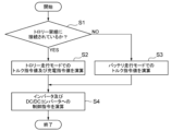
- FIG. 3 is a diagram showing an outline of the operation of the vehicle control device shown in FIG. 2 .
- 3 is a diagram showing a calculation logic relating to a torque command value of the vehicle control device shown in FIG. 2;
- FIG. 5 is a diagram showing a calculation logic related to the torque ratio shown in FIG. 4 .
- 6 is a diagram for explaining maximum power consumption and maximum regenerative power shown in FIG. 5 .
- FIG. 1 is a diagram showing the external appearance of the dump truck 1.
- the dump truck 1 is an electric dump truck that uses a battery 2 as a power source.
- the dump truck 1 is, for example, a dump truck (mining truck) that transports soil or minerals excavated in an open-cut mine.
- the dump truck 1 may be a dump truck that receives power from a trolley wire W connected to a power generation facility.
- the dump truck 1 may be equipped with a power receiving device such as a pantograph 20 that is connected to the trolley wire W.
- FIG. 2 is a diagram showing the configuration of an electrical circuit of the dump truck 1 of the first embodiment.
- FIG. 3 is a diagram showing an outline of the operation of the vehicle control device 11 shown in FIG. 2.
- the dump truck 1 includes a battery 2, a DC/DC converter 3, a smoothing capacitor 5, a battery control device 6, inverters 7 and 8, traction motors 9 and 10, and a vehicle control device 11.
- the battery 2 is the power source for the travel motors 9 and 10.
- the battery 2 is connected to the inverters 7 and 8 that drive the travel motors 9 and 10 via a DC circuit 4.
- the battery 2 discharges power when the travel motors 9 and 10 are powered, and charges power when the travel motors 9 and 10 are regenerating.
- the DC/DC converter 3 is a power conversion device that steps down or steps up the input/output voltage of the battery 2.
- the DC/DC converter 3 is provided on a DC circuit 4 that connects the battery 2 and the inverters 7 and 8.
- the DC/DC converter 3 steps up the output voltage of the battery 2 and outputs it to the DC circuit 4.
- the DC/DC converter 3 steps down the voltage of the DC circuit 4 and outputs it to the battery 2.
- the DC/DC converter 3 operates based on control commands from the vehicle control device 11. For example, the DC/DC converter 3 keeps the voltage of the DC circuit 4 constant based on a DC voltage command value from the vehicle control device 11. When the travel motors 9, 10 are powered, the voltage of the DC circuit 4 drops, so the DC/DC converter 3 keeps the voltage of the DC circuit 4 constant by discharging the battery 2. When the travel motors 9, 10 are regenerating, the voltage of the DC circuit 4 rises, so the DC/DC converter 3 keeps the voltage of the DC circuit 4 constant by charging the battery 2.
- the smoothing capacitor 5 is provided on the DC circuit 4 between the DC/DC converter 3 and the inverters 7 and 8.
- the smoothing capacitor 5 smoothes the voltage of the DC circuit 4.
- the traveling motors 9, 10 are motors for driving that rotate the drive wheels of the dump truck 1.
- the traveling motors 9, 10 are electric motors that use the battery 2 as a power source.
- the traveling motors 9, 10 are AC motors and are connected to the inverters 7, 8.
- the traveling motors 9, 10 include a left traveling motor 9 that rotates the drive wheels on the left side of the dump truck 1, and a right traveling motor 10 that rotates the drive wheels on the right side of the dump truck 1.
- the left traveling motor 9 is connected to the left traveling motor inverter 7.
- the right traveling motor 10 is connected to the right traveling motor inverter 8.
- the inverters 7 and 8 are power conversion devices that generate a voltage to drive the travel motors 9 and 10.
- the inverters 7 and 8 are connected to a DC circuit 4 that is connected to a DC/DC converter 3.
- the inverters 7 and 8 convert the DC voltage of the DC circuit 4 into a three-phase AC voltage and output the converted AC voltage to the travel motors 9 and 10 as a drive voltage.
- the inverters 7 and 8 convert the three-phase AC voltage output from the travel motors 9 and 10 into a DC voltage and output it to the DC circuit 4.
- the inverters 7 and 8 include a left travel motor inverter 7 that drives the left travel motor 9, and a right travel motor inverter 8 that drives the right travel motor 10.
- the inverters 7 and 8 operate based on control commands from the vehicle control device 11. For example, the inverters 7 and 8 adjust the output voltage (i.e., drive voltage) to the travel motors 9 and 10 based on a torque command value from the vehicle control device 11 so that the travel motors 9 and 10 rotate with a torque according to the torque command value.
- the output voltage i.e., drive voltage
- the battery control device 6 monitors the charging state of the battery 2.
- the battery control device 6 calculates the power that can be charged and discharged from the battery 2 based on the charging state of the battery 2.
- the power that can be charged and discharged from the battery 2 includes the dischargeable power indicating the power that the battery 2 can discharge, and the chargeable power indicating the power that can be charged to the battery 2.
- the dischargeable power indicates the maximum amount of power (unit: kW) that can be discharged instantly (per unit time) from the entire battery 2 when the battery 2 is discharged.
- the chargeable power indicates the maximum amount of power (unit: kW) that can be charged instantly (per unit time) from the entire battery 2 when the battery 2 is charged.
- the upper limit of the current that can be charged or discharged changes depending on the charging rate of battery 2.
- the charging rate is low, the upper limit of the dischargeable current decreases, and when the charging rate is high, the upper limit of the chargeable current decreases.
- Battery control device 6 can calculate the dischargeable power by multiplying the dischargeable current according to the charging rate of battery 2 by the terminal voltage of battery 2.
- Battery control device 6 can calculate the chargeable power by multiplying the chargeable current according to the charging rate of battery 2 by the terminal voltage of battery 2.
- the battery 2 has a configuration in which multiple secondary battery units are connected in parallel, and is configured to be operable even if one of the secondary battery units fails.
- the battery control device 6 can calculate the dischargeable power or chargeable power of the entire battery 2 from the dischargeable power or chargeable power of each secondary battery unit and the number of operable units.
- the battery control device 6 outputs the calculated dischargeable power or chargeable power of the entire battery 2 to the vehicle control device 11 via the on-board network of the dump truck 1.
- the battery control device 6 outputs the calculated dischargeable power or chargeable power to the vehicle control device 11 at regular intervals.
- the vehicle control device 11 is a control device that comprehensively controls the traveling of the dump truck 1.
- the vehicle control device 11 includes a processor and a memory, and the processor executes a program stored in the memory to realize the traveling function of the dump truck 1.
- the vehicle control device 11 can run the dump truck 1 in different running modes depending on the connection state between the pantograph 20 and the trolley overhead line W. For example, as shown in FIG. 3, the vehicle control device 11 determines whether the pantograph 20 is connected to the trolley overhead line W (step S1). If the pantograph 20 is connected to the trolley overhead line W, the vehicle control device 11 runs the dump truck 1 in the trolley running mode (step S2). On the other hand, if the pantograph 20 is not connected to the trolley overhead line W, the vehicle control device 11 runs the dump truck 1 in the battery running mode (step S3). The vehicle control device 11 then calculates each control command for the inverters 7, 8 and the DC/DC converter 3, and outputs them to the inverters 7, 8 and the DC/DC converter 3, respectively (step S4).
- the trolley driving mode is a driving mode in which the driving motors 9, 10 are driven and the battery 2 is charged using power supplied from the power generation equipment via the trolley overhead line W.
- the battery driving mode is a driving mode in which the driving motors 9, 10 are driven using power charged in the battery 2.
- the vehicle control device 11 acquires an operation signal corresponding to the acceleration/deceleration operation of the driving motors 9, 10, for example, an operation signal indicating the amount of operation of the operator on the accelerator pedal or retard (brake) pedal of the dump truck 1.
- the vehicle control device 11 calculates the target wheel torque from the acquired operation signal and wheel speed, and calculates the torque command value to be given to the inverters 7, 8.
- the power generation equipment connected to the trolley overhead line W has sufficient power supply capacity for the motor output of the driving motors 9, 10.
- the dischargeable power and chargeable power of the battery 2 change depending on the charging rate or failure status of the battery 2. Therefore, in battery driving mode, it is important for the vehicle control device 11 to calculate a torque command value that can appropriately drive the driving motors 9 and 10 while taking into account the dischargeable power and chargeable power of the battery 2.
- the vehicle control device 11 therefore limits the torque command value based on the chargeable/dischargeable power calculated by the battery control device 6. That is, the vehicle control device 11 acquires operation signals corresponding to acceleration/deceleration operations on the travel motors 9, 10, and calculates the torque command value to be output to the inverters 7, 8 based on the acquired operation signals and the chargeable/dischargeable power of the battery 2 calculated by the battery control device 6.
- the vehicle control device 11 is preset with a maximum power consumption value indicating the maximum amount of power consumed by the traveling motors 9, 10 during powering, and a maximum regenerative power value indicating the maximum amount of regenerative power generated by the traveling motors 9, 10 during regeneration.
- the vehicle control device 11 limits the torque command value so that the power consumption of the traveling motors 9, 10 does not exceed the dischargeable power.
- the vehicle control device 11 limits the torque command value so that the regenerative power of the traveling motors 9, 10 does not exceed the chargeable power.
- Figure 4 is a diagram showing the calculation logic related to the torque command value of the vehicle control device 11 shown in Figure 2.
- Figure 5 is a diagram showing the calculation logic related to the torque ratio shown in Figure 4.
- the vehicle control device 11 acquires an operation signal corresponding to the acceleration/deceleration operation of the travel motors 9, 10.
- the operation signal corresponding to the acceleration/deceleration operation indicates the amount of operation of the acceleration/deceleration operation.
- the operation signal corresponding to the acceleration/deceleration operation is an operation signal indicating the amount of operation of the accelerator pedal or retard pedal of the dump truck 1 by the operator.
- the vehicle control device 11 has a table (hereinafter also referred to as the "torque table”) preset therein that indicates the correspondence between the wheel speed of the dump truck 1 or the rotation speed of the travel motors 9, 10, and the wheel torque of the dump truck 1.
- the torque table includes an acceleration torque table used when accelerating the dump truck 1, and a deceleration torque table used when decelerating the dump truck 1.
- the vehicle control device 11 identifies the wheel torque that corresponds to the wheel speed using the torque table.
- the vehicle control device 11 calculates a torque command value by multiplying the identified wheel torque by a ratio (hereinafter also referred to as the "torque ratio”) according to the amount of acceleration/deceleration operation indicated by the acquired operation signal.
- the vehicle control device 11 calculates an acceleration torque command value by multiplying the wheel torque identified using the acceleration torque table by the torque ratio, and calculates a deceleration torque command value by multiplying the wheel torque identified using the deceleration torque table by the torque ratio.
- the vehicle control device 11 determines whether to output an acceleration torque command value or a deceleration torque command value based on the polarity of the torque ratio (positive: powering, negative: regenerative), the traveling direction of the dump truck 1, the polarity of the wheel speed, etc. as determination conditions.
- the vehicle control device 11 then outputs a command value according to the determination result to the inverters 7 and 8 as a torque command value.
- the torque ratio indicates the ratio of the torque command value to the wheel torque determined using the torque table.
- the vehicle control device 11 limits the torque command value by limiting the torque ratio based on the dischargeable power and chargeable power calculated by the battery control device 6. That is, the vehicle control device 11 sets an upper limit value of the torque ratio based on the dischargeable power calculated by the battery control device 6 and a preset maximum power consumption value. The vehicle control device 11 sets a lower limit value of the torque ratio based on the chargeable power calculated by the battery control device 6 and a preset maximum regenerative power value.
- the vehicle control device 11 calculates an upper limit value of the torque ratio by dividing the dischargeable power calculated by the battery control device 6 by a preset maximum power consumption value.
- the vehicle control device 11 calculates a lower limit value of the torque ratio by dividing the chargeable power calculated by the battery control device 6 by a preset maximum regenerative power value.
- the vehicle control device 11 sets upper and lower limit values of the calculated torque ratio.
- the vehicle control device 11 calculates the upper limit of the torque ratio as (1900/1800) x 100 ⁇ 105%.
- the vehicle control device 11 calculates the upper limit of the torque ratio as (1500/1800) x 100 ⁇ 83%.
- the dischargeable power of the battery 2 is 1200 kW
- the maximum power consumption of the traveling motors 9 and 10 is 1800 kW.
- the vehicle control device 11 calculates the upper limit of the torque ratio as (1200/1800) x 100 ⁇ 66%.
- the vehicle control device 11 After setting the upper and lower limits of the torque ratio, the vehicle control device 11 considers the accelerator signal, which is an operation signal indicating the amount of accelerator pedal operation by the operator, or the retard signal, which is an operation signal indicating the amount of retard pedal operation by the operator, to be the torque ratio input, and compares it with the set upper and lower limits of the torque ratio.
- the amount of accelerator pedal or retard pedal operation is represented as 100% when the accelerator pedal or retard pedal is fully depressed.
- the vehicle control device 11 adopts the accelerator signal or retard signal as the torque ratio to be multiplied by the wheel torque shown in FIG. 4.
- the vehicle control device 11 adopts the upper or lower limit of the exceeded torque ratio as the torque ratio to be multiplied by the wheel torque shown in FIG. 4.
- the vehicle control device 11 calculates the torque command value by multiplying the wheel torque shown in FIG. 4 by the adopted torque ratio.
- FIG. 6 is a diagram explaining the maximum power consumption and maximum regenerative power shown in FIG. 5.
- the maximum power consumption indicates the maximum amount of power consumed by the traveling motors 9, 10 during power running.
- the maximum regenerative power indicates the maximum amount of regenerative power generated by the traveling motors 9, 10 during regeneration.
- the maximum power consumption and maximum regenerative power are determined in advance by the specifications of the dump truck 1 (hereinafter also referred to as "vehicle specifications"), including the specifications of the traveling motors 9, 10, and are parameters that are preset in the vehicle control device 11.
- the torque table showing the correspondence between the wheel speed of the dump truck 1 or the rotation speed of the traveling motors 9, 10 and the wheel torque of the dump truck 1 is determined by the vehicle body specifications.
- the wheel torque can be converted into the motor torque T (unit: N ⁇ m) of the traveling motors 9, 10 from the wheel diameter and reduction ratio of the dump truck 1.
- the maximum value of the motor output that can be determined by the vehicle body specifications (hereinafter also referred to as the "maximum motor output") is acquired.
- the maximum power consumption can be calculated by adding to the maximum motor output the efficiency of the traction motors 9, 10 and the power conversion efficiency of the inverters 7, 8.
- the maximum regenerative power can be calculated by subtracting the power conversion efficiency of the inverters 7, 8 from the maximum motor output.
- the maximum power consumption and maximum regenerative power are determined in advance based on the vehicle specifications and are set in advance in the vehicle control device 11.
- the dump truck 1 of the first embodiment includes the battery 2, the traveling motors 9, 10 powered by the battery 2, the inverters 7, 8 that generate the drive voltage for the traveling motors 9, 10, the DC/DC converter 3 that steps down or steps up the input/output voltage of the battery 2, a smoothing capacitor 5 provided between the DC/DC converter 3 and the inverters 7, 8, the battery control device 6 that monitors the charge state of the battery 2, and the vehicle control device 11 that outputs a torque command value for the traveling motors 9, 10 to the inverters 7, 8 to control the drive of the traveling motors 9, 10.
- the battery control device 6 calculates the chargeable and dischargeable power of the battery 2 based on the charge state of the battery 2.
- the vehicle control device 11 acquires an operation signal corresponding to an acceleration/deceleration operation on the traveling motors 9, 10, and calculates a torque command value to be output to the inverters 7, 8 based on the acquired operation signal and the chargeable and dischargeable power calculated by the battery control device 6.
- the vehicle control device 11 can limit the power consumption and regeneration power of the traveling motors 9, 10 to less than the power that can be charged and discharged from the battery 2. Therefore, the vehicle control device 11 can prevent the DC circuit 4 from becoming undervoltage or overvoltage. Therefore, the dump truck 1 of embodiment 1 can stabilize the voltage of the DC circuit 4, and can prevent the traveling system from stopping and parts from being damaged.
- the vehicle control device 11 has preset maximum power consumption values and maximum regenerative power values of the traveling motors 9, 10.
- the battery control device 6 calculates the dischargeable power and chargeable power of the battery 2. If the dischargeable power is smaller than the maximum power consumption value, the vehicle control device 11 limits the torque command value so that the power consumption of the traveling motors 9, 10 does not exceed the dischargeable power. If the chargeable power is smaller than the maximum regenerative power value, the vehicle control device 11 limits the torque command value so that the regenerative power of the traveling motors 9, 10 does not exceed the chargeable power.
- the vehicle control device 11 can reliably limit the power consumed and the regenerative power of the traveling motors 9, 10 to below the dischargeable power and chargeable power of the battery 2. Therefore, the vehicle control device 11 can reliably prevent the DC circuit 4 from becoming undervoltage, and can reliably prevent the DC circuit 4 from becoming overvoltage. Therefore, the dump truck 1 of embodiment 1 can reliably stabilize the voltage of the DC circuit 4, and can reliably prevent the traveling system from stopping and parts from being damaged.
- a torque table is preset in the vehicle control device 11.
- the vehicle control device 11 uses the torque table to identify the wheel torque corresponding to the wheel speed.
- the vehicle control device 11 calculates a torque command value by multiplying the identified wheel torque by a torque ratio according to the amount of acceleration/deceleration operation indicated by the operation signal.
- the vehicle control device 11 limits the torque command value by setting an upper limit value of the torque ratio based on the dischargeable power of the battery 2 and the maximum power consumption of the traveling motors 9 and 10, and setting a lower limit value of the torque ratio based on the chargeable power of the battery 2 and the maximum regenerative power of the traveling motors 9 and 10.
- the vehicle control device 11 can reliably limit the power consumed and the regenerated power of the traveling motors 9, 10 to below the dischargeable power and the chargeable power of the battery 2 without using any special calculation logic or algorithm. Therefore, the vehicle control device 11 can reliably and easily prevent undervoltage and overvoltage states of the DC circuit 4. Therefore, the dump truck 1 of embodiment 1 can reliably and easily stabilize the voltage of the DC circuit 4, and can reliably and easily prevent the traveling system from stopping and parts from being damaged.
- FIG. 7 is a diagram showing the configuration of an electric circuit of the dump truck 1 of the second embodiment.
- FIG. 8 is a diagram showing the calculation logic related to the torque ratio of the vehicle control device 11 shown in FIG. 7.
- the dump truck 1 of the second embodiment includes a left resistor 12 and a left chopper 13 connected in parallel to the left traveling motor inverter 7, and a right resistor 14 and a right chopper 15 connected in parallel to the right traveling motor inverter 8. That is, the left resistor 12 and the left chopper 13 are connected to the DC circuit 4 between the smoothing capacitor 5 and the left traveling motor inverter 7. The right resistor 14 and the right chopper 15 are connected to the DC circuit 4 between the smoothing capacitor 5 and the right traveling motor inverter 8.
- the vehicle control device 11 of the second embodiment controls the DC/DC converter 3 to charge the battery 2 with the regenerative power of the driving motors 9, 10, and also controls the choppers 13, 15 to consume the surplus power in the resistors 12, 14.
- the choppers 13, 15 supply the regenerative power of the driving motors 9, 10 to the resistors 12, 14 based on a control command from the vehicle control device 11.
- the resistors 12, 14 convert the supplied regenerative power into heat and consume it.
- a resistor consumable power indicating the power that can be consumed by the resistors 12 and 14 is preset.
- the resistor consumable power is determined in advance by the specifications of the resistors 12 and 14, and is a parameter that is preset in the vehicle control device 11.
- the resistor consumable power may correspond to the capacity of the resistors 12 and 14.
- the vehicle control device 11 of the second embodiment sets the lower limit of the torque ratio based on the chargeable power calculated by the battery control device 6, as well as the preset maximum regenerative power value and the resistor consumable power.
- the vehicle control device 11 of the second embodiment calculates the lower limit of the torque ratio by dividing the sum of the chargeable power calculated by the battery control device 6 and the preset resistor consumable power by the preset maximum regenerative power value.
- the vehicle control device 11 of the second embodiment calculates the lower limit of the torque ratio by dividing the preset resistor consumable power by the preset maximum regenerative power value.
- a state in which the battery 2 is non-chargeable refers to a state in which the charging rate of the battery 2 is 100%, or a state in which the battery 2 or the DC/DC converter 3, etc., is broken and the battery 2 cannot be charged.
- the vehicle control device 11 calculates the magnitude of the lower limit of the torque ratio as ⁇ (1900 + 1800) / 2900 ⁇ x 100 ⁇ 127%.
- the vehicle control device 11 calculates the magnitude of the lower limit of the torque ratio as ⁇ (1000 + 1800) / 2900 ⁇ x 100 ⁇ 96%.
- the vehicle control device 11 calculates the magnitude of the lower limit of the torque ratio as ⁇ (0 + 1800) / 2900 ⁇ x 100 ⁇ 62%. The vehicle control device 11 multiplies the calculated magnitude of the lower limit of the torque ratio by -1 to set the lower limit of the torque ratio as a negative value.
- the vehicle control device 11 of embodiment 2 calculates the upper limit of the torque ratio by dividing the dischargeable power calculated by the battery control device 6 by a preset maximum power consumption value.
- the dump truck 1 of the second embodiment further includes resistors 12, 14 that are connected between the smoothing capacitor 5 and the inverters 7, 8 and consume the regenerative power of the traveling motors 9, 10.
- the vehicle control device 11 is preset with resistor consumable power indicating the power that can be consumed by the resistors 12, 14.
- the vehicle control device 11 sets a lower limit of the torque ratio based on the chargeable power of the battery 2, the maximum regenerative power of the traveling motors 9, 10, and the resistor consumable power of the resistors 12, 14.
- the vehicle control device 11 can thereby limit the power consumption and regenerative power of the traveling motors 9, 10 to less than the dischargeable power and chargeable power of the battery 2, while reducing the rate of decrease in the torque command value associated with a decrease in the chargeable power. Therefore, the vehicle control device 11 can reduce the opportunities for the chargeable power to be lower than the maximum regenerative power, and reduce the opportunities for limiting the torque command value during deceleration. Therefore, the vehicle control device 11 can easily maintain the original regenerative braking performance of the traveling motors 9, 10, and can suppress wear on the mechanical brakes of the dump truck 1. Therefore, the dump truck 1 of embodiment 2 can stabilize the voltage of the DC circuit 4, and can suppress the running costs of the dump truck 1 while preventing the traveling system from stopping and parts from being damaged.
- the vehicle control device 11 calculates the upper limit of the torque ratio by dividing the dischargeable power of the battery 2 by the maximum power consumption of the traveling motors 9 and 10.
- the vehicle control device 11 calculates the lower limit of the torque ratio by dividing the sum of the chargeable power of the battery 2 and the resistor consumable power of the resistors 12 and 14 by the maximum regenerative power of the traveling motors 9 and 10.
- the vehicle control device 11 calculates the lower limit of the torque ratio by dividing the resistor consumable power by the maximum regenerative power.
- the vehicle control device 11 can maintain the regenerative braking performance of the travel motors 9, 10 even if the battery 2 falls into a state where it cannot be charged, while limiting the power consumption and regenerative power of the travel motors 9, 10 to below the dischargeable power and chargeable power of the battery 2. Therefore, the vehicle control device 11 can further reduce wear on the mechanical brakes of the dump truck 1. Therefore, the dump truck 1 of embodiment 2 can stabilize the voltage of the DC circuit 4, and can further reduce the running costs of the dump truck 1 while preventing the travel system from stopping and parts from being damaged.
- the present invention is not limited to the above embodiments, and various modifications can be made without departing from the spirit of the present invention described in the claims.
- the present invention allows the configuration of one embodiment to be added to the configuration of another embodiment, the configuration of one embodiment to be replaced with another embodiment, or part of the configuration of one embodiment to be deleted.
Landscapes
- Engineering & Computer Science (AREA)
- Power Engineering (AREA)
- Transportation (AREA)
- Mechanical Engineering (AREA)
- Life Sciences & Earth Sciences (AREA)
- Sustainable Development (AREA)
- Sustainable Energy (AREA)
- Electric Propulsion And Braking For Vehicles (AREA)
Priority Applications (3)
| Application Number | Priority Date | Filing Date | Title |
|---|---|---|---|
| JP2025510076A JPWO2024202934A1 (https=) | 2023-03-30 | 2024-03-01 | |
| CN202480005281.1A CN120359141A (zh) | 2023-03-30 | 2024-03-01 | 自卸卡车 |
| EP24779072.8A EP4691827A1 (en) | 2023-03-30 | 2024-03-01 | Dump truck |
Applications Claiming Priority (2)
| Application Number | Priority Date | Filing Date | Title |
|---|---|---|---|
| JP2023054655 | 2023-03-30 | ||
| JP2023-054655 | 2023-03-30 |
Publications (1)
| Publication Number | Publication Date |
|---|---|
| WO2024202934A1 true WO2024202934A1 (ja) | 2024-10-03 |
Family
ID=92905654
Family Applications (1)
| Application Number | Title | Priority Date | Filing Date |
|---|---|---|---|
| PCT/JP2024/007804 Ceased WO2024202934A1 (ja) | 2023-03-30 | 2024-03-01 | ダンプトラック |
Country Status (4)
| Country | Link |
|---|---|
| EP (1) | EP4691827A1 (https=) |
| JP (1) | JPWO2024202934A1 (https=) |
| CN (1) | CN120359141A (https=) |
| WO (1) | WO2024202934A1 (https=) |
Cited By (1)
| Publication number | Priority date | Publication date | Assignee | Title |
|---|---|---|---|---|
| US20210197744A1 (en) * | 2018-08-14 | 2021-07-01 | Ford Global Technologies, Llc | Dynamic control of on-board generator inverter input power |
Citations (4)
| Publication number | Priority date | Publication date | Assignee | Title |
|---|---|---|---|---|
| JP2003204603A (ja) * | 2002-01-08 | 2003-07-18 | Nissan Motor Co Ltd | ハイブリッド車両の制御装置 |
| WO2013024869A1 (ja) * | 2011-08-16 | 2013-02-21 | 日立建機株式会社 | 作業車両 |
| WO2016051501A1 (ja) * | 2014-09-30 | 2016-04-07 | 日立建機株式会社 | 運搬車両 |
| JP6350031B2 (ja) | 2014-06-30 | 2018-07-04 | 株式会社デンソー | 車両用制御装置 |
-
2024
- 2024-03-01 WO PCT/JP2024/007804 patent/WO2024202934A1/ja not_active Ceased
- 2024-03-01 EP EP24779072.8A patent/EP4691827A1/en active Pending
- 2024-03-01 JP JP2025510076A patent/JPWO2024202934A1/ja active Pending
- 2024-03-01 CN CN202480005281.1A patent/CN120359141A/zh active Pending
Patent Citations (4)
| Publication number | Priority date | Publication date | Assignee | Title |
|---|---|---|---|---|
| JP2003204603A (ja) * | 2002-01-08 | 2003-07-18 | Nissan Motor Co Ltd | ハイブリッド車両の制御装置 |
| WO2013024869A1 (ja) * | 2011-08-16 | 2013-02-21 | 日立建機株式会社 | 作業車両 |
| JP6350031B2 (ja) | 2014-06-30 | 2018-07-04 | 株式会社デンソー | 車両用制御装置 |
| WO2016051501A1 (ja) * | 2014-09-30 | 2016-04-07 | 日立建機株式会社 | 運搬車両 |
Non-Patent Citations (1)
| Title |
|---|
| See also references of EP4691827A1 |
Cited By (1)
| Publication number | Priority date | Publication date | Assignee | Title |
|---|---|---|---|---|
| US20210197744A1 (en) * | 2018-08-14 | 2021-07-01 | Ford Global Technologies, Llc | Dynamic control of on-board generator inverter input power |
Also Published As
| Publication number | Publication date |
|---|---|
| CN120359141A (zh) | 2025-07-22 |
| EP4691827A1 (en) | 2026-02-11 |
| JPWO2024202934A1 (https=) | 2024-10-03 |
Similar Documents
| Publication | Publication Date | Title |
|---|---|---|
| JP6909694B2 (ja) | 作業車両の電力回生システム | |
| US10680540B2 (en) | Apparatus for controlling motorized vehicle | |
| KR100419937B1 (ko) | 하이브리드 전기 자동차의 회생 제어장치 | |
| US11007893B2 (en) | Control device for electric vehicle and electric vehicle | |
| CN103545902B (zh) | 具有dc链的电气系统 | |
| JP5494979B2 (ja) | 電動車両 | |
| US10875408B2 (en) | Apparatus for controlling motorized vehicle | |
| US11091058B2 (en) | Fuel cell system | |
| JP2008295300A (ja) | 蓄電器を備えた車両の電力制限装置 | |
| JP6410757B2 (ja) | 動力システム及び輸送機器、並びに、電力伝送方法 | |
| WO2015071977A1 (ja) | 充放電システム | |
| US20190263275A1 (en) | Apparatus for controlling motorized vehicle | |
| CN110316019A (zh) | 车辆电源系统 | |
| JP3892528B2 (ja) | ハイブリッド電気自動車の補助電源バッテリ充電制御装置 | |
| JP3886940B2 (ja) | ハイブリッド車両の制御装置 | |
| WO2015071970A1 (ja) | 充放電システム | |
| JP5419745B2 (ja) | シリーズハイブリッド車両の制御装置 | |
| JP5912624B2 (ja) | ハイブリッド車両の制御装置 | |
| JP3094701B2 (ja) | 電気自動車用エンジン駆動発電機の制御装置 | |
| WO2024202934A1 (ja) | ダンプトラック | |
| JP7053919B1 (ja) | ダンプトラックのドライブシステム | |
| JP4500217B2 (ja) | 回路装置 | |
| CN115848167A (zh) | 工程车辆的控制方法、装置、可读存储介质和工程车辆 | |
| JP7759755B2 (ja) | ダンプトラック | |
| JP2005245104A (ja) | 電気自動車 |
Legal Events
| Date | Code | Title | Description |
|---|---|---|---|
| 121 | Ep: the epo has been informed by wipo that ep was designated in this application |
Ref document number: 24779072 Country of ref document: EP Kind code of ref document: A1 |
|
| WWE | Wipo information: entry into national phase |
Ref document number: 2025510076 Country of ref document: JP |
|
| WWE | Wipo information: entry into national phase |
Ref document number: CN2024800052811 Country of ref document: CN Ref document number: 202480005281.1 Country of ref document: CN |
|
| WWP | Wipo information: published in national office |
Ref document number: 202480005281.1 Country of ref document: CN |
|
| WWE | Wipo information: entry into national phase |
Ref document number: 2024779072 Country of ref document: EP |
|
| NENP | Non-entry into the national phase |
Ref country code: DE |
|
| ENP | Entry into the national phase |
Ref document number: 2024779072 Country of ref document: EP Effective date: 20251030 |
|
| ENP | Entry into the national phase |
Ref document number: 2024779072 Country of ref document: EP Effective date: 20251030 |
|
| ENP | Entry into the national phase |
Ref document number: 2024779072 Country of ref document: EP Effective date: 20251030 |
|
| ENP | Entry into the national phase |
Ref document number: 2024779072 Country of ref document: EP Effective date: 20251030 |
|
| ENP | Entry into the national phase |
Ref document number: 2024779072 Country of ref document: EP Effective date: 20251030 |
|
| ENP | Entry into the national phase |
Ref document number: 2024779072 Country of ref document: EP Effective date: 20251030 |
|
| ENP | Entry into the national phase |
Ref document number: 2024779072 Country of ref document: EP Effective date: 20251030 |
|
| ENP | Entry into the national phase |
Ref document number: 2024779072 Country of ref document: EP Effective date: 20251030 |
|
| WWP | Wipo information: published in national office |
Ref document number: 2024779072 Country of ref document: EP |