WO2024202909A1 - 電動ポンプ - Google Patents
電動ポンプ Download PDFInfo
- Publication number
- WO2024202909A1 WO2024202909A1 PCT/JP2024/007650 JP2024007650W WO2024202909A1 WO 2024202909 A1 WO2024202909 A1 WO 2024202909A1 JP 2024007650 W JP2024007650 W JP 2024007650W WO 2024202909 A1 WO2024202909 A1 WO 2024202909A1
- Authority
- WO
- WIPO (PCT)
- Prior art keywords
- bearing
- accommodating recess
- drive shaft
- rotor
- electric pump
- Prior art date
- Legal status (The legal status is an assumption and is not a legal conclusion. Google has not performed a legal analysis and makes no representation as to the accuracy of the status listed.)
- Ceased
Links
Images



Classifications
-
- F—MECHANICAL ENGINEERING; LIGHTING; HEATING; WEAPONS; BLASTING
- F04—POSITIVE - DISPLACEMENT MACHINES FOR LIQUIDS; PUMPS FOR LIQUIDS OR ELASTIC FLUIDS
- F04C—ROTARY-PISTON, OR OSCILLATING-PISTON, POSITIVE-DISPLACEMENT MACHINES FOR LIQUIDS; ROTARY-PISTON, OR OSCILLATING-PISTON, POSITIVE-DISPLACEMENT PUMPS
- F04C14/00—Control of, monitoring of, or safety arrangements for, machines, pumps or pumping installations
-
- F—MECHANICAL ENGINEERING; LIGHTING; HEATING; WEAPONS; BLASTING
- F04—POSITIVE - DISPLACEMENT MACHINES FOR LIQUIDS; PUMPS FOR LIQUIDS OR ELASTIC FLUIDS
- F04C—ROTARY-PISTON, OR OSCILLATING-PISTON, POSITIVE-DISPLACEMENT MACHINES FOR LIQUIDS; ROTARY-PISTON, OR OSCILLATING-PISTON, POSITIVE-DISPLACEMENT PUMPS
- F04C15/00—Component parts, details or accessories of machines, pumps or pumping installations, not provided for in groups F04C2/00 - F04C14/00
-
- F—MECHANICAL ENGINEERING; LIGHTING; HEATING; WEAPONS; BLASTING
- F04—POSITIVE - DISPLACEMENT MACHINES FOR LIQUIDS; PUMPS FOR LIQUIDS OR ELASTIC FLUIDS
- F04C—ROTARY-PISTON, OR OSCILLATING-PISTON, POSITIVE-DISPLACEMENT MACHINES FOR LIQUIDS; ROTARY-PISTON, OR OSCILLATING-PISTON, POSITIVE-DISPLACEMENT PUMPS
- F04C2/00—Rotary-piston machines or pumps
- F04C2/08—Rotary-piston machines or pumps of intermeshing-engagement type, i.e. with engagement of co-operating members similar to that of toothed gearing
- F04C2/10—Rotary-piston machines or pumps of intermeshing-engagement type, i.e. with engagement of co-operating members similar to that of toothed gearing of internal-axis type with the outer member having more teeth or tooth-equivalents, e.g. rollers, than the inner member
Definitions
- the present invention relates to an electric pump.
- JP2010-112302A discloses an electric pump unit in which a pump, an electric motor for driving the pump, and a motor controller are assembled in a unit housing.
- a bearing is provided on the outer circumferential surface of the pump drive motor shaft, which is driven by the motor. The bearing is press-fitted into the housing of the electric pump unit.
- the present invention aims to improve the maintainability of electric pumps.
- an electric pump includes a pump section that discharges liquid, a motor section that drives the pump section by rotating a drive shaft, and a housing that accommodates the pump section and the motor section.
- a bearing that rotatably supports the drive shaft is provided on the outer circumferential surface of the drive shaft, and the housing has a bearing accommodating recess in which the bearing is accommodated.
- the bearing accommodating recess accommodates a support ring that is provided in contact with the surface of the bearing on the opening side of the bearing accommodating recess and is held in the bearing accommodating recess to support the bearing, and a biasing ring that is provided between the bearing and the bottom surface of the bearing accommodating recess and biases the bearing toward the support ring.
- FIG. 1 is a perspective view of an electric pump according to an embodiment of the present invention.
- FIG. 2 is a cross-sectional view of the electric pump according to the embodiment of the present invention.
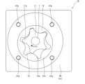
- FIG. 3 is a plan view of the pump portion.
- FIG. 4 is a plan view of the rotor.
- the electric pump 100 is mounted, for example, on a vehicle and discharges a coolant (liquid) for cooling an electric motor mounted on the vehicle, or discharges oil (liquid) for lubricating gears mounted on the vehicle.
- the electric pump 100 may be used as a fluid pressure supply source that discharges a working fluid (liquid) for driving equipment.
- the electric pump 100 may also be mounted on industrial machinery other than a vehicle.
- FIG. 1 is a perspective view of the electric pump 100
- FIG. 2 is a cross-sectional view of the electric pump 100 taken along line II-II in FIG. 1.
- the electric pump 100 includes a pump section 10 that discharges liquid, a motor section 20 that drives the pump section 10 by rotating a drive shaft 1, a control section 30 that controls the motor section 20, and a housing 40 that houses the pump section 10, the motor section 20, and the control section 30.
- the control section 30, the motor section 20, and the pump section 10 are arranged in this order from the top in FIGS. 1 and 2.
- the axial direction of the drive shaft 1 will also be referred to simply as the "axial direction”
- the radial direction of the drive shaft 1 will also be referred to simply as the "radial direction”.
- FIG. 3 is a plan view of the pump section 10 seen from below in FIGS. 1 and 2, with the pump cover section 56 of the housing 40 covering the pump section 10 removed.
- the pump section 10 is an internal gear pump having an inner rotor 11 to which the drive shaft 1 is connected, and an outer rotor 12 arranged on the outside of the inner rotor 11.
- the inner rotor 11 and the outer rotor 12 are housed in the housing 40 (specifically, the housing main body section 41 described below), are arranged eccentrically with respect to each other, and are covered by the pump cover section 56 of the housing 40.
- the inner rotor 11 is arranged so that its center overlaps with the drive shaft 1
- the outer rotor 12 is arranged so that its center is offset from the drive shaft 1.
- the inner rotor 11 has a plurality of external teeth 11a on its outer peripheral surface
- the outer rotor 12 has a plurality of internal teeth 12a on its inner peripheral surface that slide against the external teeth 11a.
- the external teeth 11a and the internal teeth 12a are formed with different numbers of teeth, and a pump chamber 13 is defined by adjacent external teeth 11a of the inner rotor 11 and internal teeth 12a of the outer rotor 12. Multiple pump chambers 13 are formed in the pump section 10.
- the pump cover part 56 that covers the pump part 10 is formed with a suction port (not shown) that guides liquid from the outside to the pump chamber 13, and a discharge port (not shown) that guides liquid discharged from the pump chamber 13 to the outside.
- a suction port (not shown) that guides liquid from the outside to the pump chamber 13
- a discharge port (not shown) that guides liquid discharged from the pump chamber 13 to the outside.
- the motor section 20 has an annular stator 21 and a rotor 25 arranged radially inside the stator 21.
- the stator 21 and the rotor 25 are housed in a housing 40 (specifically, a housing main body section 41, which will be described later).
- the stator 21 has an annular stator core 22 arranged to surround the rotor 25, and coil wire 23 wound around the stator core 22.
- the stator core 22 has an annular yoke portion 22a that contacts the inner peripheral surface of the housing 40 (housing body portion 41), and a plurality of teeth portions 22b that protrude radially inward from the yoke portion 22a and are arranged at predetermined intervals in the circumferential direction.
- the yoke portion 22a is formed with a plurality of protrusions 22c that protrude in the axial direction toward the control unit 30.
- the coil wire 23 is wound around the teeth portions 22b of the stator core 22. As a result, a U-phase coil, a V-phase coil, and a W-phase coil corresponding to the three-phase drive current are formed on each tooth portion 22b.
- the ends of each coil wire 23 are connected to the control unit 30.
- FIG. 4 is a plan view of rotor 25 seen from above in Figure 2.
- rotor 25 has a rotor core 26 provided on the outer peripheral surface of drive shaft 1 and rotating together with drive shaft 1, and a plurality of permanent magnets 27 provided on the outer peripheral surface of rotor core 26.
- Permanent magnets 27 are arranged in an annular shape, with north and south poles arranged alternately.
- Rotor core 26 has an annular wall portion 26a (see Figure 2) provided on the inner peripheral surface of permanent magnet 27, and a disk portion 26b provided at one axial end of wall portion 26a.
- Disk portion 26b is provided at the upper end of wall portion 26a in Figure 2.
- the disk portion 26b is provided with a maintenance hole 26c (see FIG.
- the rotor 25 rotates around the drive shaft 1 due to the action of the magnetized state of the stator core 22 of the stator 21 and the permanent magnet 27. This drives the pump portion 10.
- a bearing 60 that rotatably supports the drive shaft 1 and an oil seal 75 are provided on the outer circumferential surface of the drive shaft 1 driven by the motor unit 20.
- the bearing 60 and the oil seal 75 are housed in the housing 40.
- the control unit 30 controls the current supplied to the stator 21 to drive the motor unit 20.
- the control unit 30 has electronic components 31 and a substrate 32 on which the electronic components 31 are mounted and to which the coil wire 23 of the motor unit 20 is connected.
- the electronic components 31 include, for example, a magnetic detection sensor such as a Hall element that can detect changes in magnetism that change according to the rotation of the drive shaft 1, and a calculation unit that calculates the rotation angle and rotation speed of the drive shaft 1 based on the detection value of the magnetic detection sensor.
- the control unit 30 controls the direction of the current flowing through the coil wire 23 of the stator 21 according to the rotation angle of the drive shaft 1, and controls the magnitude of the current supplied to the coil wire 23 so that the rotation speed of the drive shaft 1 becomes the target rotation speed input from the outside.
- the electronic components 31 are mounted on both sides of the substrate 32.
- a heat dissipation unit 33 that dissipates heat from the substrate 32 is provided on the substrate 32 on the opposite side to the motor unit 20 (the upper side in
- the housing 40 has a housing body portion 41 having an opening 42, a cover portion 51 that covers the opening 42, and a pump cover portion 56 that covers the pump portion 10.
- the housing body 41 has an insertion hole 43 through which the drive shaft 1 is inserted, an annular motor accommodating recess 44 in which the motor section 20 is accommodated, a bearing accommodating recess 45 provided radially inside the motor accommodating recess 44 in which the bearing 60 and the like are accommodated, an oil seal accommodating recess 46 formed axially continuous with the bearing accommodating recess 45 in which the oil seal 75 is accommodated, and a pump accommodating recess 47 in which the pump section 10 is accommodated.
- the insertion hole 43 is formed to extend axially through the opening 42, the bearing accommodating recess 45, the oil seal accommodating recess 46, and the pump accommodating recess 47.
- the motor accommodating recess 44 is formed to be continuous with the opening 42, and has an outer inner circumferential surface 44a, which is an inner circumferential surface located on the radially outer side, and an inner inner circumferential surface 44b, which is an inner circumferential surface located on the radially inner side.
- the annular yoke portion 22a of the stator core 22 of the motor section 20 is provided in contact with the outer inner circumferential surface 44a, and the wall portion 26a of the rotor core 26 of the rotor 25 faces the inner inner circumferential surface 44b.
- the rotor core 26 is provided in the motor accommodating recess 44 provided radially outward, so that the bearing accommodating recess 45 is covered by the disk portion 26b of the rotor core 26.
- the rotor core 26 is provided so that the disk portion 26b seals the opening 45a of the bearing accommodating recess 45.
- the maintenance hole 26c of the rotor 25 faces the bearing accommodating recess 45.
- the bearing accommodating recess 45 accommodates a bearing 60 provided on the outer circumferential surface of the drive shaft 1 and rotatably supporting the drive shaft 1, an annular snap ring 65 as a support ring supporting the bearing 60, and an annular washer 70 as a biasing ring biasing the bearing 60 toward the snap ring 65.
- the bearing accommodating recess 45 is located inside the rotor 25 in this way, and the bearing 60 and the like are accommodated therein, so that the axial dimension can be reduced.
- the bearing 60 is not press-fitted into the bearing accommodating recess 45, and the fit between the bearing 60 and the bearing accommodating recess 45 is a "loose fit".
- An annular groove 45b for holding a snap ring 65 is formed in the opening 45a of the bearing accommodating recess 45, which is formed on the opening 42 side of the housing body 41 (upper side in FIG. 2).
- the snap ring 65 is provided in contact with the surface of the bearing accommodating recess 45 on the opening 45a side of the bearing 60, and is held in the bearing accommodating recess 45 by being accommodated in the groove 45b, thereby supporting the bearing 60.
- the snap ring 65 can be expanded and contracted in the radial direction, and can be switched between a state in which it is held in the bearing accommodating recess 45 and a state in which it is not held (in other words, a state in which it is accommodated in the groove 45b and a state in which it is not accommodated).
- the rotor 25 is formed with a maintenance hole 26c facing the bearing accommodating recess 45, so that the snap ring 65 can be visually observed through the maintenance hole 26c of the rotor 25 (see FIG. 4). Therefore, the snap ring 65 can be expanded or contracted by inserting a tool (not shown) into the maintenance hole 26c and fitting it into the openings 65a provided at both circumferential ends of the snap ring 65.
- the maintenance hole 26c is formed so that two openings 65a of the snap ring 65 face each other, so that the snap ring 65 can be expanded or contracted by a tool.
- the maintenance hole 26c is formed to a size such that one opening 65a faces each of two maintenance holes 26c, or two openings 65a face each of one maintenance hole 26c.
- the washer 70 is provided between the bearing 60 and the bottom surface 45c of the bearing accommodating recess 45, and biases the bearing 60 toward the snap ring 65. Therefore, the bearing 60 is held in the bearing accommodating recess 45 while being pressed against the snap ring 65 by the washer 70. This prevents the bearing 60 from rattling in the axial direction.
- the oil seal accommodating recess 46 is formed with a smaller diameter than the bearing accommodating recess 45 and accommodates the oil seal 75.
- the oil seal accommodating recess 46 is provided between the bearing accommodating recess 45 and the pump accommodating recess 47.
- the pump accommodating recess 47 is formed with its center offset from the insertion hole 43 to accommodate the inner rotor 11 and outer rotor 12 of the pump section 10.
- a plurality of fastening holes 47a are formed on the end face of the pump accommodating recess 47 to which fastening members (not shown) for attaching the pump cover section 56 are fastened (see FIG. 3).
- the cover portion 51 has a protrusion 51a that protrudes on the side opposite the housing main body portion 41 (upward in FIG. 2).
- the protrusion 51a is formed hollow, and the board 32 and heat dissipation portion 33 of the control portion 30 are housed in the hollow portion of the protrusion 51a.
- the board 32 housed in the housing 40 is electrically connected to the outside by a connector (not shown) provided on the housing main body portion 41.
- the cover portion 51 is fixed to the housing main body portion 41 by a fastening member 81.
- the pump cover portion 56 is provided to cover the pump accommodating recess 47.
- An insertion hole (not shown) through which a fastening member (not shown) is inserted is formed in the pump cover portion 56, and the pump cover portion 56 is fixed to the housing main body portion 41 by the fastening member.
- the pump cover portion 56 is formed with the suction port 56a and the discharge port 56b as described above.
- the oil seal 75 is placed in the oil seal accommodating recess 46, and the washer 70 is placed in the bearing accommodating recess 45. Then, the bearing 60 is press-fitted onto the drive shaft 1. Next, the drive shaft 1 with the bearing 60 pressed into it is inserted into the insertion hole 43 from the opening 42 side of the housing body 41. This attaches the oil seal 75 to the outer circumferential surface of the drive shaft 1, and the bearing 60 abuts against the washer 70. Then, the snap ring 65 is placed and held in the groove 45b of the bearing accommodating recess 45. The axial position of the drive shaft 1 with the bearing 60 and oil seal 75 attached thereto relative to the housing 40 is determined by the snap ring 65 being held in the groove 45b.
- the insertion hole 26d of the rotor 25 is pressed into the drive shaft 1 to accommodate the rotor 25 in the motor accommodating recess 44.
- the cylindrical portion 26e of the rotor 25 is inserted into the hollow portion of the snap ring 65 and abuts against the bearing 60.
- the stator 21 is then accommodated in the motor accommodating recess 44, and the pump portion 10 is further accommodated in the pump accommodating recess 47.
- the cover portion 51 of the housing 40 to which the control portion 30 is attached, and the pump cover portion 56 are attached to the housing main body portion 41, completing the assembly of the electric pump 100.
- the bearing 60 is supported by the snap ring 65 under the biasing force of the washer 70, rather than being pressed in, and is held in the bearing accommodating recess 45. Therefore, the bearing 60 can be easily removed from the housing 40 simply by removing the snap ring 65 from the bearing accommodating recess 45. Specifically, the drive shaft, rotor 25, and bearing 60 can be easily removed from the housing 40 as an integrated assembly simply by removing the snap ring 65 from the groove 45b and then from the bearing accommodating recess 45. This improves the maintainability of the electric pump 100.
- the drive shaft 1, bearing 60, oil seal 75, rotor 25, and stator 21 are all inserted from the opening 42 side of the housing body 41 and assembled. Therefore, when disassembling the electric pump 100 for maintenance, all of these components can be removed from one direction, improving the maintainability of the electric pump 100.
- the above components are inserted from one direction and assembled, so the inner surface of the housing 40 can be machined from one direction. Therefore, the coaxiality of the above components is improved compared to a case where the above components are inserted from two different directions and the inner surface of the housing 40 needs to be machined from two directions.
- the snap ring 65 is accommodated in the groove 45b to hold the bearing 60 in the bearing accommodating recess 45, making it easy to determine the axial position of the drive shaft 1 relative to the housing 40.
- the bearing 60 can be easily removed from the housing 40 together with the drive shaft 1 and rotor 25 by switching the snap ring 65 to a state where it is not held in the bearing accommodating recess 45 through the maintenance hole 26c of the rotor 25.
- the cylindrical portion 26e of the rotor 25 is inserted into the hollow portion of the snap ring 65 and abuts against the bearing 60. This increases the contact area (press-fit area) between the drive shaft 1 and the rotor 25, so the hollow portion of the snap ring 65 can be used to more firmly connect the drive shaft 1 and the rotor 25.
- the bearing 60 is supported by the snap ring 65 under the biasing force of the washer 70 and is held in the bearing accommodating recess 45. Therefore, the bearing 60 can be easily removed from the housing 40 by simply removing the snap ring 65 from the bearing accommodating recess 45, improving the maintainability of the electric pump 100.
- an annular groove 45b is formed in the bearing accommodating recess 45, and the snap ring 65 is held in the groove 45b to hold the bearing 60 in the bearing accommodating recess 45, thereby determining the axial position of the drive shaft 1 relative to the housing 40.
- the groove 45b does not have to be annular as long as the snap ring 65 can be held therein.
- the groove 45b is not essential, and the snap ring 65 may be held in the bearing accommodating recess 45 by a configuration other than the groove 45b.
- the oil seal 75 is provided on the outer circumferential surface of the drive shaft 1, and the housing body 41 of the housing 40 has the oil seal accommodating recess 46.
- the oil seal 75 and the oil seal accommodating recess 46 are not essential components of the electric pump 100.
- the motor accommodating recess 44 is provided radially outward of the bearing accommodating recess 45.
- the bearing accommodating recess 45 is located inside the rotor 25 and accommodates the bearing 60 and the like, making it possible to reduce the axial dimension of the electric pump 100.
- the motor accommodating recess 44 may be provided alongside the bearing accommodating recess 45 in the axial direction rather than radially outward of the bearing accommodating recess 45, although this would increase the axial dimension of the electric pump 100.
- the rotor 25 (rotor core 26) is formed with the maintenance hole 26c and the cylindrical portion 26e into which the drive shaft 1 is press-fitted.
- the maintenance hole 26c and the cylindrical portion 26e are not essential components of the electric pump 100.
- the electric pump 100 comprises a pump section 10 that discharges liquid, a motor section 20 that drives the pump section 10 by rotating the drive shaft 1, and a housing 40 that houses the pump section 10 and the motor section 20.
- a bearing 60 that rotatably supports the drive shaft 1 is provided on the outer peripheral surface of the drive shaft 1, and the housing 40 has a bearing accommodating recess 45 in which the bearing 60 is accommodated.
- the bearing accommodating recess 45 accommodates a snap ring 65 that is provided in contact with the surface of the bearing 60 on the side of the opening 45a of the bearing accommodating recess 45 and serves as a support ring that is held in the bearing accommodating recess 45 and supports the bearing 60, and a washer 70 that is provided between the bearing 60 and the bottom surface 45c of the bearing accommodating recess 45 and serves as a biasing ring that biases the bearing 60 toward the snap ring 65.
- the bearing 60 is supported by the snap ring 65 under the biasing force of the washer 70 and is held in the bearing accommodating recess 45. Therefore, the bearing 60 can be easily removed from the housing 40 by simply removing the snap ring 65 from the bearing accommodating recess 45. This improves the maintainability of the electric pump 100.
- an oil seal 75 is further provided on the outer circumferential surface of the drive shaft 1, and the housing 40 further has an oil seal accommodating recess 46 that is continuous with the bearing accommodating recess 45 and has a smaller diameter than the bearing accommodating recess 45 and accommodates the oil seal 75, and a groove 45b that holds a snap ring 65 is formed in the bearing accommodating recess 45, and the axial position of the drive shaft 1 provided with the bearing 60 and oil seal 75 relative to the housing 40 is determined by the snap ring 65 being held in the groove 45b.
- the snap ring 65 is accommodated in the groove 45b to hold the bearing 60 in the bearing accommodating recess 45, making it easy to determine the axial position of the drive shaft 1 relative to the housing 40.
- the motor section 20 has an annular stator 21 and a rotor 25 arranged radially inside the stator 21, and the housing 40 further has an annular motor accommodating recess 44 that is provided radially outside the bearing accommodating recess 45 and accommodates the stator 21 and the rotor 25.
- the bearing accommodating recess 45 is located inside the rotor 25 and accommodates the bearings 60, etc., making it possible to reduce the axial dimension of the electric pump 100.
- the rotor 25 is formed with a maintenance hole 26c that penetrates the rotor 25 in the axial direction and faces the bearing accommodating recess 45, and the snap ring 65 can be switched between a state in which it is held in the bearing accommodating recess 45 and a state in which it is not held through the maintenance hole 26c.
- the bearing 60 can be easily removed from the housing 40 by switching the snap ring 65 to a state where it is not held in the bearing accommodating recess 45 through the maintenance hole 26c of the rotor 25.
- the rotor 25 is formed with a cylindrical portion 26e into which the drive shaft 1 is press-fitted, and the cylindrical portion is inserted into the hollow portion of the snap ring 65 and abuts against the bearing 60.
- the hollow portion of the snap ring 65 can be used to more firmly connect the drive shaft 1 and the rotor 25.
Landscapes
- Engineering & Computer Science (AREA)
- Mechanical Engineering (AREA)
- General Engineering & Computer Science (AREA)
- Details And Applications Of Rotary Liquid Pumps (AREA)
Priority Applications (1)
| Application Number | Priority Date | Filing Date | Title |
|---|---|---|---|
| JP2025510061A JPWO2024202909A1 (https=) | 2023-03-28 | 2024-02-29 |
Applications Claiming Priority (2)
| Application Number | Priority Date | Filing Date | Title |
|---|---|---|---|
| JP2023051945 | 2023-03-28 | ||
| JP2023-051945 | 2023-03-28 |
Publications (1)
| Publication Number | Publication Date |
|---|---|
| WO2024202909A1 true WO2024202909A1 (ja) | 2024-10-03 |
Family
ID=92905259
Family Applications (1)
| Application Number | Title | Priority Date | Filing Date |
|---|---|---|---|
| PCT/JP2024/007650 Ceased WO2024202909A1 (ja) | 2023-03-28 | 2024-02-29 | 電動ポンプ |
Country Status (2)
| Country | Link |
|---|---|
| JP (1) | JPWO2024202909A1 (https=) |
| WO (1) | WO2024202909A1 (https=) |
Citations (4)
| Publication number | Priority date | Publication date | Assignee | Title |
|---|---|---|---|---|
| JPH0667924U (ja) * | 1993-02-26 | 1994-09-22 | エヌティエヌ株式会社 | セパレートロール用軸受装置 |
| JPH10246187A (ja) * | 1997-03-04 | 1998-09-14 | Showa:Kk | ポンプ軸受部のオイルシール構造 |
| JP2010112302A (ja) * | 2008-11-07 | 2010-05-20 | Jtekt Corp | 電動ポンプユニット |
| JP2016537564A (ja) * | 2013-11-05 | 2016-12-01 | ターボネティクス ホールディングス, インコーポレイテッドTurbonetics Holdings, Inc. | ターボチャージャ二重ボールベアリングシステム |
-
2024
- 2024-02-29 JP JP2025510061A patent/JPWO2024202909A1/ja active Pending
- 2024-02-29 WO PCT/JP2024/007650 patent/WO2024202909A1/ja not_active Ceased
Patent Citations (4)
| Publication number | Priority date | Publication date | Assignee | Title |
|---|---|---|---|---|
| JPH0667924U (ja) * | 1993-02-26 | 1994-09-22 | エヌティエヌ株式会社 | セパレートロール用軸受装置 |
| JPH10246187A (ja) * | 1997-03-04 | 1998-09-14 | Showa:Kk | ポンプ軸受部のオイルシール構造 |
| JP2010112302A (ja) * | 2008-11-07 | 2010-05-20 | Jtekt Corp | 電動ポンプユニット |
| JP2016537564A (ja) * | 2013-11-05 | 2016-12-01 | ターボネティクス ホールディングス, インコーポレイテッドTurbonetics Holdings, Inc. | ターボチャージャ二重ボールベアリングシステム |
Also Published As
| Publication number | Publication date |
|---|---|
| JPWO2024202909A1 (https=) | 2024-10-03 |
Similar Documents
| Publication | Publication Date | Title |
|---|---|---|
| JP7464089B2 (ja) | 電動オイルポンプ | |
| JP5850263B2 (ja) | 駆動装置 | |
| JP5927870B2 (ja) | 電動ポンプ | |
| JP2008175090A (ja) | 電動ポンプ | |
| JP2019112979A (ja) | 電動オイルポンプ | |
| KR20110127311A (ko) | 완전 방수구조를 갖는 유체 펌프 | |
| JP2012189015A (ja) | 電動ポンプユニット | |
| CN104104163B (zh) | 旋转电机的定子铁心固定结构 | |
| JP2018025127A (ja) | ポンプ装置 | |
| CN111213305A (zh) | 驱动装置 | |
| JP5969416B2 (ja) | 電動モータおよび電動ポンプ | |
| US20140125166A1 (en) | Rotating electrical machine | |
| JP2018038099A (ja) | 電動モータ | |
| JP2012207638A (ja) | 内接歯車ポンプ | |
| JP6819392B2 (ja) | 電動オイルポンプ装置及び電動オイルポンプ用ベースプレート | |
| JP2014062482A (ja) | 電動ポンプ | |
| JP2022165783A (ja) | ポンプ | |
| WO2024202909A1 (ja) | 電動ポンプ | |
| JP2004293787A (ja) | モータハウジングとアクセス部品とを備えた電気モータ | |
| WO2025197632A1 (ja) | 電動ポンプ | |
| WO2024202910A1 (ja) | 電動ポンプ | |
| JP2025035228A (ja) | 電動ポンプ | |
| JP2013115836A (ja) | ブラシレスモータ及び電動ポンプ | |
| JPH0233879B2 (https=) | ||
| JP2025035227A (ja) | 電動ポンプユニット |
Legal Events
| Date | Code | Title | Description |
|---|---|---|---|
| 121 | Ep: the epo has been informed by wipo that ep was designated in this application |
Ref document number: 24779047 Country of ref document: EP Kind code of ref document: A1 |
|
| DPE1 | Request for preliminary examination filed after expiration of 19th month from priority date (pct application filed from 20040101) | ||
| ENP | Entry into the national phase |
Ref document number: 2025510061 Country of ref document: JP Kind code of ref document: A |
|
| WWE | Wipo information: entry into national phase |
Ref document number: 2025510061 Country of ref document: JP |
|
| NENP | Non-entry into the national phase |
Ref country code: DE |
|
| 122 | Ep: pct application non-entry in european phase |
Ref document number: 24779047 Country of ref document: EP Kind code of ref document: A1 |