WO2024202350A1 - 鞍乗り型車両 - Google Patents
鞍乗り型車両 Download PDFInfo
- Publication number
- WO2024202350A1 WO2024202350A1 PCT/JP2023/046912 JP2023046912W WO2024202350A1 WO 2024202350 A1 WO2024202350 A1 WO 2024202350A1 JP 2023046912 W JP2023046912 W JP 2023046912W WO 2024202350 A1 WO2024202350 A1 WO 2024202350A1
- Authority
- WO
- WIPO (PCT)
- Prior art keywords
- vehicle
- light
- saddle
- irradiated
- irradiation
- Prior art date
- Legal status (The legal status is an assumption and is not a legal conclusion. Google has not performed a legal analysis and makes no representation as to the accuracy of the status listed.)
- Ceased
Links
Images






Classifications
-
- B—PERFORMING OPERATIONS; TRANSPORTING
- B62—LAND VEHICLES FOR TRAVELLING OTHERWISE THAN ON RAILS
- B62J—CYCLE SADDLES OR SEATS; AUXILIARY DEVICES OR ACCESSORIES SPECIALLY ADAPTED TO CYCLES AND NOT OTHERWISE PROVIDED FOR, e.g. ARTICLE CARRIERS OR CYCLE PROTECTORS
- B62J6/00—Arrangement of optical signalling or lighting devices on cycles; Mounting or supporting thereof; Circuits therefor
- B62J6/02—Headlights
- B62J6/022—Headlights specially adapted for motorcycles or the like
- B62J6/023—Headlights specially adapted for motorcycles or the like responsive to the lean angle of the cycle, e.g. changing intensity or switching sub-lights when cornering
-
- B—PERFORMING OPERATIONS; TRANSPORTING
- B60—VEHICLES IN GENERAL
- B60Q—ARRANGEMENT OF SIGNALLING OR LIGHTING DEVICES, THE MOUNTING OR SUPPORTING THEREOF OR CIRCUITS THEREFOR, FOR VEHICLES IN GENERAL
- B60Q1/00—Arrangement of optical signalling or lighting devices, the mounting or supporting thereof or circuits therefor
- B60Q1/02—Arrangement of optical signalling or lighting devices, the mounting or supporting thereof or circuits therefor the devices being primarily intended to illuminate the way ahead or to illuminate other areas of way or environments
- B60Q1/24—Arrangement of optical signalling or lighting devices, the mounting or supporting thereof or circuits therefor the devices being primarily intended to illuminate the way ahead or to illuminate other areas of way or environments for lighting other areas than only the way ahead
-
- B—PERFORMING OPERATIONS; TRANSPORTING
- B60—VEHICLES IN GENERAL
- B60Q—ARRANGEMENT OF SIGNALLING OR LIGHTING DEVICES, THE MOUNTING OR SUPPORTING THEREOF OR CIRCUITS THEREFOR, FOR VEHICLES IN GENERAL
- B60Q1/00—Arrangement of optical signalling or lighting devices, the mounting or supporting thereof or circuits therefor
- B60Q1/26—Arrangement of optical signalling or lighting devices, the mounting or supporting thereof or circuits therefor the devices being primarily intended to indicate the vehicle, or parts thereof, or to give signals, to other traffic
- B60Q1/50—Arrangement of optical signalling or lighting devices, the mounting or supporting thereof or circuits therefor the devices being primarily intended to indicate the vehicle, or parts thereof, or to give signals, to other traffic for indicating other intentions or conditions, e.g. request for waiting or overtaking
-
- B—PERFORMING OPERATIONS; TRANSPORTING
- B62—LAND VEHICLES FOR TRAVELLING OTHERWISE THAN ON RAILS
- B62J—CYCLE SADDLES OR SEATS; AUXILIARY DEVICES OR ACCESSORIES SPECIALLY ADAPTED TO CYCLES AND NOT OTHERWISE PROVIDED FOR, e.g. ARTICLE CARRIERS OR CYCLE PROTECTORS
- B62J6/00—Arrangement of optical signalling or lighting devices on cycles; Mounting or supporting thereof; Circuits therefor
- B62J6/04—Rear lights
-
- B—PERFORMING OPERATIONS; TRANSPORTING
- B62—LAND VEHICLES FOR TRAVELLING OTHERWISE THAN ON RAILS
- B62J—CYCLE SADDLES OR SEATS; AUXILIARY DEVICES OR ACCESSORIES SPECIALLY ADAPTED TO CYCLES AND NOT OTHERWISE PROVIDED FOR, e.g. ARTICLE CARRIERS OR CYCLE PROTECTORS
- B62J27/00—Safety equipment
-
- B—PERFORMING OPERATIONS; TRANSPORTING
- B62—LAND VEHICLES FOR TRAVELLING OTHERWISE THAN ON RAILS
- B62J—CYCLE SADDLES OR SEATS; AUXILIARY DEVICES OR ACCESSORIES SPECIALLY ADAPTED TO CYCLES AND NOT OTHERWISE PROVIDED FOR, e.g. ARTICLE CARRIERS OR CYCLE PROTECTORS
- B62J6/00—Arrangement of optical signalling or lighting devices on cycles; Mounting or supporting thereof; Circuits therefor
- B62J6/22—Warning or information lights
-
- F—MECHANICAL ENGINEERING; LIGHTING; HEATING; WEAPONS; BLASTING
- F21—LIGHTING
- F21S—NON-PORTABLE LIGHTING DEVICES; SYSTEMS THEREOF; VEHICLE LIGHTING DEVICES SPECIALLY ADAPTED FOR VEHICLE EXTERIORS
- F21S43/00—Signalling devices specially adapted for vehicle exteriors, e.g. brake lamps, direction indicator lights or reversing lights
- F21S43/10—Signalling devices specially adapted for vehicle exteriors, e.g. brake lamps, direction indicator lights or reversing lights characterised by the light source
- F21S43/13—Signalling devices specially adapted for vehicle exteriors, e.g. brake lamps, direction indicator lights or reversing lights characterised by the light source characterised by the type of light source
- F21S43/14—Light emitting diodes [LED]
-
- F—MECHANICAL ENGINEERING; LIGHTING; HEATING; WEAPONS; BLASTING
- F21—LIGHTING
- F21S—NON-PORTABLE LIGHTING DEVICES; SYSTEMS THEREOF; VEHICLE LIGHTING DEVICES SPECIALLY ADAPTED FOR VEHICLE EXTERIORS
- F21S43/00—Signalling devices specially adapted for vehicle exteriors, e.g. brake lamps, direction indicator lights or reversing lights
- F21S43/30—Signalling devices specially adapted for vehicle exteriors, e.g. brake lamps, direction indicator lights or reversing lights characterised by reflectors
-
- F—MECHANICAL ENGINEERING; LIGHTING; HEATING; WEAPONS; BLASTING
- F21—LIGHTING
- F21W—INDEXING SCHEME ASSOCIATED WITH SUBCLASSES F21K, F21L, F21S and F21V, RELATING TO USES OR APPLICATIONS OF LIGHTING DEVICES OR SYSTEMS
- F21W2107/00—Use or application of lighting devices on or in particular types of vehicles
- F21W2107/10—Use or application of lighting devices on or in particular types of vehicles for land vehicles
- F21W2107/13—Use or application of lighting devices on or in particular types of vehicles for land vehicles for cycles
- F21W2107/17—Use or application of lighting devices on or in particular types of vehicles for land vehicles for cycles for motorcycles
Definitions
- the present invention relates to a saddle-type vehicle.
- Some vehicles are equipped with auxiliary lamps in the headlight unit that illuminate areas other than the headlight illumination area.
- auxiliary lamps in the headlight unit that illuminate areas other than the headlight illumination area.
- large-angle lamps, medium-angle lamps, and large diffusion lamps are arranged in that order from the center of the vehicle to the outside, and the large diffusion lamps are configured to illuminate areas from the front to the sides and even the rear of the area near the vehicle, making it easier for the driver to see pedestrians, bicycles, etc. that are near the vehicle.
- the main purpose of conventional configurations is to enable drivers to check for pedestrians, bicycles, etc., and is not primarily intended to make it easier for drivers of other vehicles and pedestrians to notice vehicles.
- the present invention has been made in consideration of the above-mentioned circumstances, and has an object to make it easier for others outside the vehicle to recognize a saddle-ride type vehicle when the saddle-ride type vehicle is tilted to the left or right.
- the present invention provides a saddle-ride type vehicle having a lighting device, the lighting device emitting a predetermined light having a higher brightness than headlight light and taillight light at a predetermined position spaced from the vehicle, and the emitting direction of the predetermined light is at least one of the front side of the vehicle, the rear side of the vehicle, and the side of the vehicle, and at least one of the upward and downward directions when the vehicle is upright.
- FIG. 1 is a side view of a saddle-ride type vehicle according to an embodiment of the present invention.
- FIG. 2 is a schematic diagram showing the light unit from above the vehicle body.
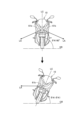
- FIG. 3 is a diagram illustrating the first light that is irradiated downward from the front of the vehicle when the vehicle is upright.
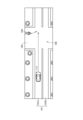
- FIG. 4 is a top view showing a traveling situation in which a plurality of vehicles are traveling.
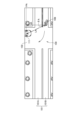
- FIG. 5 is a top view showing the saddle type vehicle together with another vehicle.
- FIG. 6 is a diagram illustrating the first light that is irradiated upward from the front of the vehicle when the vehicle is upright.
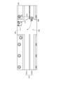
- FIG. 7 is a top view showing the saddle type vehicle together with another vehicle.
- FIG. 1 is a side view of a saddle-ride type vehicle according to an embodiment of the present invention.
- FIG. 2 is a schematic diagram showing the light unit from above the vehicle body.
- FIG. 3 is a diagram illustrating the first light that is irradiated downward from the front of
- FIG. 8 is a diagram showing a rear light unit according to another embodiment as viewed from above the vehicle body.
- FIG. 9 is a top view showing a saddle-ride type vehicle according to another embodiment together with another vehicle.
- FIG. 10 is a top view showing a saddle-ride type vehicle according to another embodiment together with another vehicle.
- FIG. 1 is a side view of a saddle-ride type vehicle 10 according to an embodiment of the present invention.
- the saddle-type vehicle 10 is a vehicle that includes a body frame 11, a power unit 12 supported by the body frame 11, a front fork 14 that supports a front wheel 13 so as to be freely steerable, a swing arm 16 that supports a rear wheel 15, and a seat 17 for a passenger.
- the saddle-ride type vehicle 10 is a vehicle in which a passenger sits astride a seat 17.
- the seat 17 is provided above the rear portion of the body frame 11.
- the body frame 11 includes a head pipe 18 provided at the front end of the body frame 11, a front frame 19 located rearward of the head pipe 18, and a rear frame 20 located rearward of the front frame 19.
- the front end of the front frame 19 is connected to the head pipe 18.
- the seat 17 is supported by a rear frame 20 .
- the front fork 14 is supported by a head pipe 18 so that it can be steered left and right.
- the front wheel 13 is supported by an axle 13a provided at the lower end of the front fork 14.
- a steering handle 21 that is held by the rider is attached to the upper end of the front fork 14.
- the swing arm 16 is supported by a pivot shaft 22 that is supported by the body frame 11.
- the pivot shaft 22 is a shaft that extends horizontally in the vehicle width direction.
- the pivot shaft 22 is inserted into the front end of the swing arm 16.
- the swing arm 16 swings up and down about the pivot shaft 22.
- the rear wheel 15 is supported by an axle 15 a provided at the rear end of a swing arm 16 .
- the power unit 12 is disposed between the front wheels 13 and the rear wheels 15 and is supported by the body frame 11 .
- the power unit 12 is an internal combustion engine.
- the power unit 12 includes a crankcase 23 and a cylinder portion 24 that houses a reciprocating piston.
- An exhaust device 25 is connected to an exhaust port of the cylinder portion 24.
- the output of the power unit 12 is transmitted to the rear wheel 15 by a driving force transmission member that connects the power unit 12 and the rear wheel 15 .
- the saddle-type vehicle 10 also includes a front fender 26 that covers the front wheel 13 from above, a rear fender 27 that covers the rear wheel 15 from above, a step 28 on which a rider places his or her feet, and a fuel tank 29 that stores fuel used by the power unit 12.
- the front fender 26 is attached to the front fork 14.
- the rear fender 27 and the step 28 are provided below the seat 17.
- the fuel tank 29 is supported by the body frame 11.
- the saddle-ride type vehicle 10 includes a vehicle body cover 30 that covers the vehicle body.
- the vehicle body cover 30 includes a front cover 31 that covers the front part of the vehicle body from the front and the left and right sides, and an inner cover 32 that covers the front frame 19 from above.
- the front cover 31 is a cover shape that expands in the vehicle width direction and the up and down direction as it goes rearward, and is formed in a left-right symmetrical shape based on the center of the vehicle width.
- a light unit 41 that emits headlight light is attached to the front cover 31.
- the headlight light is a low beam (a so-called passing headlight) and a high beam (a so-called driving headlight).
- a rear light unit 45 that emits taillight light is attached to the rear of the saddle-ride type vehicle 10.
- the taillight light is light equivalent to a taillight (tail lamp) or a brake lamp.
- the saddle-ride type vehicle 10 is not limited to the configuration shown in FIG. 1, and the configuration and shape of each part may be changed.
- the light unit 41 is a unit constituting a part of the lighting equipment of the saddle-ride type vehicle 10, and is also called a headlight unit or a front light unit.
- the light unit 41 is located forward of the center of the front-rear direction of the vehicle body of the saddle-ride type vehicle 10, and more specifically, forward of the steering handlebar 21a and the vehicle body frame 11.
- This light unit 41 may be either a so-called handlebar mount type supported by the handlebar 21, or a so-called frame mount type supported by the vehicle body frame 11.
- This light unit 41 has a function of emitting light LA that improves the visibility of the saddle-ride type vehicle 10 from others outside the vehicle.
- This light LA is a light with a small divergence angle, such as parallel light or quasi-parallel light, and thus has a higher brightness at a predetermined position away from the saddle-ride type vehicle 10 than the headlight light, taillight light, and turn signal light, which are generally diffused light.
- the predetermined position is a position in the direction in which the light LA is irradiated, and can also be said to be a position farther away than the headlight light, taillight light, and turn signal light, or a position away from the irradiation range of the headlight light, taillight light, and turn signal light.
- the predetermined position includes the position of the driver of another vehicle 111 (FIG. 5, etc.) based on the saddle-ride type vehicle 10 tilted to the left and right, as described later.
- This light LA corresponds to the "predetermined light" of the present invention.
- the irradiation direction of the light LA can be either downward when the vehicle is standing upright or upward when the vehicle is standing upright.
- downward when the vehicle is upright can be referred to as a direction toward the left and right outer side of the vehicle and toward the bottom of the vehicle when the vehicle is upright, or in this embodiment, as a direction downward relative to the height of a reflector 61b (see FIG. 2) described later.
- Fig. 2 is a schematic diagram of the light unit 41 from above the vehicle.
- the reference character LC in Fig. 2 indicates the center of the vehicle width.
- Fig. 2 also shows a configuration related to the irradiation/stop of irradiation of the irradiation light LA, which will be described later.
- the light unit 41 has a housing 42 (also called a housing) extending outward to the left and right based on the vehicle width center LC, and within the housing 42 are a pair of left and right light sources 61a and a pair of left and right reflectors 61b that reflect the light from each light source 61a to become irradiation light LA.
- Each light source 61a is a known light source such as an LED, and emits visible light.
- the light source 61a is not limited to a point light source, but may be a surface light source in which multiple light-emitting elements are densely arranged to emit surface light.
- Surface light sources are, for example, COB (Chips on Board) type or SMD (Surface Mount Device) type LEDs.
- Each reflector 61b is formed on a reflecting mirror that irradiates light from the light source 61a in the irradiation direction of the irradiation light LA.
- a reflecting mirror is adopted for each reflector 61b, in which an area capable of irradiating a predetermined width of light LA in a desired direction is formed on the reflecting surface of a paraboloid of revolution with the position of the light source 61a as a focus.
- the irradiation light LA consisting of parallel light is irradiated by the reflector 61b.
- the irradiation light LA By making the irradiation light LA parallel, it becomes easier to maintain a certain level of brightness higher than the light of the surroundings (e.g., corresponding to the headlight light, taillight light, turn signal light, and ambient light), and it becomes easier for others to recognize the irradiation light LA.
- the width of the parallel light may be set appropriately.
- the illumination light LA is not limited to parallel light, and may be, for example, quasi-parallel light. Quasi-parallel light is divergent light close to parallel light. Since the divergence angle of quasi-parallel light is small, it can irradiate light with a certain level of brightness to a relatively long distance, similar to parallel light.
- the reflecting surface of each reflector 61b may be a reflecting surface that approximates a paraboloid of revolution.
- the reflectors 61b and the light sources 61a are fixed to the light unit 41. Therefore, the irradiation direction of each of the lights LA emitted from the saddle type vehicle 10 is fixed. In this configuration, as shown in FIG. 2, the reflectors 61b irradiate the illumination light LA to the left and right when viewed from above the vehicle.
- FIG. 3 is a diagram showing a schematic view of the irradiated light LA from the front of the vehicle.
- 3 shows the saddle-ride type vehicle 10 in an upright state and in an inclined state (also called a banked state) inclined to one side (left or right) of the vehicle.
- the upright state is a state in which the vehicle body stands vertically with respect to the running surface GR (corresponding to the road or ground), and the inclination angle ⁇ K of the vehicle body based on the running surface GR is 90° (corresponding to a bank angle of 0°).
- each light LA is irradiated toward the lower left side of the vehicle and the lower right side of the vehicle when viewed from the front of the vehicle.
- the irradiation direction of the irradiated light LA on the outside which is the opposite side of the tilt direction, can be made more horizontal than the irradiation direction in the upright state. This makes it easier to irradiate the irradiated light LA toward others on the outside who you want to be aware of when the saddle-ride type vehicle 10 is leaning. It also makes it easier to irradiate the irradiated light LA into the distance.
- a vehicle 10A located at an intersection 100 is illustrated.
- the vehicle 10A is located on a second road 102 and is about to turn left into a lane 101A of a first road 101 (a lane in which another vehicle 111 is traveling).
- Fig. 5 is a diagram showing the vehicle 10A together with another vehicle 111 from above.
- the vehicle 10A is stopped immediately before turning left, and the steering wheel 21 is steered to the left turn side, causing the vehicle 10A to bank to the left (corresponding to the inside) by a predetermined angle ⁇ K1.
- ⁇ K1 a predetermined angle
- the predetermined angle ⁇ K1 is appropriately set based on the inclination angle ⁇ K of the vehicle 10A when turning on the perpendicular road.
- the vehicle 10A irradiates the irradiation light LA in the direction of an angle ⁇ 1 corresponding to any one of the front side, the side, and the rear side of the vehicle when viewed from above the vehicle body.
- this angle ⁇ 1 is a direction in which the irradiation light LA is irradiated toward the driver of the other vehicle 111 when the other vehicle 111 is located at position P1 and the steering angle to the left side is generated in the handle 21 of the vehicle 10A and the vehicle 10A is banking, and Fig.
- the irradiation light LA is toward the rear side of the vehicle based on the vehicle 10A.
- the light unit 41 can easily irradiate the irradiated light LA toward the driver of the other vehicle 111, based on the vehicle 10A, when a steering angle occurs on the steering wheel 21 of the steering wheel-mounted vehicle 10A for turning left.
- the irradiation direction of the irradiated light LA may be set to be below the vehicle when the vehicle is upright, either to the side of the vehicle or to the front side of the vehicle.
- Position P1 is a distance d1 from the vehicle 10A, and is set to a suitable position for the other vehicle 111 to avoid contact with the vehicle 10A based on simulations and experiments.
- the angle ⁇ 1 is the direction in which the irradiated light LA is directed toward the driver of the other vehicle 111 when the other vehicle 111 is located at position P1, and for example, the direction in which the irradiated light LA is directed downward from the vehicle when the vehicle is upright, toward the front side of the vehicle, the side of the vehicle, or the rear side of the vehicle.
- the other vehicle 111 shown in FIG. 5 is a vehicle traveling on the first road 101, and is a vehicle that may follow the vehicle 10A after the vehicle 10A makes a left turn.
- Position P1 is set, for example, at a position where the other vehicle 111 can avoid contact with the vehicle 10A, or at a position where the other vehicle 111 can stop.
- the irradiated light LA can be irradiated toward the driver of the other vehicle 111 at position P1.
- the irradiated light LA can be irradiated closer to the horizontal direction than when the vehicle 10A is upright, and the irradiated light LA can be irradiated at a height that is easily perceptible by the driver of the other vehicle 111.
- the driver of the other vehicle 111 which may be a following vehicle, can recognize the irradiated light LA, in other words, the driver of the other vehicle 111 can be made aware of the presence of the vehicle 10A. As a result, the driver of the other vehicle 111 can recognize the vehicle 10A, and the visibility of the vehicle 10A is improved.
- the saddle-ride type vehicle 10 includes an information acquisition unit 81 and a vehicle control unit 82 as components related to the irradiation/stopping of irradiation of the irradiation light LA.
- the information acquisition unit 81 is a device that detects information of each part of the saddle-ride type vehicle 10.
- the information acquisition unit 81 includes at least a vehicle speed detection unit 81a that detects the vehicle speed of the saddle-ride type vehicle 10, and a tilt angle detection unit 81b that detects the left/right tilt angle ⁇ K of the saddle-ride type vehicle 10.
- the vehicle control unit 82 is a device that controls each part of the saddle-ride type vehicle 10, and has an illumination control unit 82a that controls the illumination/stop of illumination of the illumination light LA.
- the illumination control unit 82a may also have a function of controlling the turning on/off of headlights, turn signals, tail lights, brake lights, etc.
- the illumination control unit 82a controls the light source 61a to be turned on and illuminated with illumination light LA only when the vehicle 10A is stopped based on the vehicle speed of the vehicle 10A. This allows the illumination light LA to be illuminated when the vehicle 10A is stopped. Therefore, as shown in FIG. 5, it becomes easier for the driver of another vehicle 111, which may be a following vehicle after turning right or left, to recognize the vehicle 10A, and it becomes easier to prevent the illumination light LA from being illuminated when the vehicle is not stopped.
- the illumination control unit 82a may be configured to irradiate only the outside light LA, which is the opposite side of the tilt direction.
- the illumination control unit 82a can specify the tilt direction by using the tilt angle ⁇ K detected by the tilt angle detection unit 81b, and control to irradiate the outside light LA but not the inside light LA.
- the illumination control unit 82a may also control the illumination light LA to be emitted only when the vehicle 10A is stopped and the inclination angle ⁇ K of the vehicle 10A is within a predetermined range. In this case, the illumination light LA can be prevented from being emitted when the vehicle 10A is stopped but not in a banked state (corresponding to when the inclination angle ⁇ K is outside the predetermined range).
- the illumination light LA is irradiated only when the vehicle 10A is stopped.
- the illumination light LA may be irradiated not only when the vehicle 10A is stopped but also when the vehicle 10A is turning right or left at a low speed.
- the illumination control unit 82a may control the illumination light LA to be irradiated only when the vehicle 10A is at or below a predetermined speed, and the predetermined speed may be set so that the predetermined speed or below includes only when the vehicle 10A is stopped, or the predetermined speed may be set so that the vehicle 10A is at or below a low speed in addition to when the vehicle 10A is stopped.
- the illumination light LA can be irradiated while the vehicle 10A is turning right or left while banking, which is expected to improve the visibility of the vehicle 10A.
- the above-mentioned predetermined speed it is possible to prevent the irradiation of the irradiated light LA when traveling at a high speed range where right and left turns are not made. Therefore, even if an occupant of another vehicle is in a position where the irradiated light LA from the vehicle 10A is irradiated while traveling straight at a high speed range, it is possible to avoid a situation where the irradiated light LA is irradiated to the occupant.
- FIG. 6 is a diagram showing a schematic view of the irradiated light LA from the front of the vehicle. 6 shows the saddle type vehicle 10 in an upright state and in an inclined state (also called a banked state) inclined to one side (left or right) of the vehicle 10. As shown in FIG. 6, each light LA is irradiated toward the upper left side of the vehicle and the upper right side of the vehicle, respectively, when viewed from the front of the vehicle.
- the irradiation direction of each light LA in this manner, when the tilt angle ⁇ K of the saddle-ride type vehicle 10 is a predetermined angle ⁇ K1, as shown in FIG. 6, the irradiation direction of the light LA on the inside side, which is the tilt direction side, can be made more horizontal than the irradiation direction in the upright state. This makes it easier to irradiate the irradiated light LA toward others on the inside side who you want to be aware of when the saddle-ride type vehicle 10 is leaning. It also makes it easier to irradiate the irradiated light LA into the distance.
- FIG. 7 shows a saddle-type vehicle 10, vehicle 10B, from above, immediately before making a right turn at intersection 100.
- This vehicle 10B is located on first road 101 (the opposite lane (also called the oncoming road) 101B of lane 101A) and is about to make a right turn onto second road 102 that intersects with first road 101.
- first road 101 the opposite lane (also called the oncoming road) 101B of lane 101A)
- second road 102 that intersects with first road 101.
- the steering wheel 21 is steered to the right turn side while the vehicle is stopped, and vehicle 10B is banked to the right (corresponding to the inside) at a predetermined angle ⁇ K1.
- the vehicle 10B irradiates the illumination light LA in a direction of an angle corresponding to either the front side or the side of the vehicle when viewed from above the vehicle body.
- this angle ⁇ A is a direction in which the driver of the other vehicle 111 recognizes the illumination light LA when the other vehicle 111 is located at position PA and the steering angle for turning right is generated on the handle 21 of the vehicle 10B.
- Fig. 7 illustrates an example in which the illumination light LA is in the front side of the vehicle with the vehicle 10B as a reference.
- the light unit 41 is of a handle-mount type, and even when a steering angle occurs on the handle 21 of the vehicle 10A when turning right or left, the irradiated light LA can be easily irradiated toward the driver of the other vehicle 111 with the vehicle 10A as the reference.
- the direction of irradiation of the irradiated light LA may be above the vehicle when the vehicle is upright and toward the side of the vehicle.
- the position PA is a distance dA from the vehicle 10B, and is set to a position that is suitable for the other vehicle 111 to avoid contact with the vehicle 10A based on simulations and experiments.
- the angle ⁇ A is a direction in which the irradiated light LA is irradiated toward the driver of the other vehicle 111 when the other vehicle 111 is located at position P1, and for example, the direction of irradiation of the irradiated light LA is above the vehicle when the vehicle is upright and toward either the front side or the side of the vehicle.
- the other vehicle 111 shown in FIG. 7 is a vehicle traveling on the second road 102 after the vehicle 10B turns right, and is a vehicle that may be an oncoming vehicle of the vehicle 10B after the vehicle 10A turns right.
- Position PA is set to, for example, a position where the other vehicle 111 can avoid contact with the vehicle 10B or a position where the other vehicle 111 can stop. This allows the irradiated light LA to be irradiated toward the driver of the other vehicle 111 at position PA when viewed from above the vehicle.
- the vehicle 10B is inclined to the right at a predetermined angle ⁇ K1
- the irradiated light LA can be irradiated closer to the horizontal direction, and the irradiated light LA can be irradiated at a height where the driver of the other vehicle 111 can easily perceive it.
- Fig. 7 shows only the light LA on the inside side, which is the inclination direction side.
- the illumination control unit 82a controls the illumination light LA to be emitted only when the vehicle 10B is stopped, so the illumination light LA is emitted when the vehicle 10B is stopped. Therefore, as shown in FIG. 7, it becomes easier for the driver of the other vehicle 111, which may be an oncoming vehicle after turning right or left, to recognize the vehicle 10B, and it becomes easier to prevent the illumination light LA from being emitted when the vehicle is not stopped.
- the irradiation control unit 82a may be configured to irradiate only the inside light LA, which is the inclination direction side.
- the irradiation control unit 82a can specify the inclination direction by using the inclination angle ⁇ K detected by the inclination angle detection unit 81b, and perform control to irradiate the inside light LA and not irradiate the outside light LA.
- the vehicle 10B may be a vehicle that is about to make a U-turn or is about to make a U-turn. In this case, when the vehicle 10B is in a banked state just before making a U-turn, the driver of the other vehicle 111 traveling on the second road 102 perpendicular to the vehicle 10B can be made aware of the vehicle 10B.
- the illumination control unit 82a controls the illumination light LA to be emitted only when the vehicle speed of the vehicle 10B is below a predetermined speed and the inclination angle ⁇ K of the vehicle 10B is within a predetermined range, so that the illumination light LA is not emitted when the vehicle 10B is stopped but not in a banked state.
- the vehicle speed of the vehicle 10B being equal to or lower than the predetermined speed does not have to be limited to the case where the vehicle 10B is stopped, and may be set to include, for example, a low-speed state when the vehicle 10B turns right or left (including a U-turn). This makes it possible to irradiate the irradiated light LA while the vehicle 10B is banking and turning right or left or making a U-turn at a low speed, and is expected to have the effect of improving the visibility of the vehicle 10B.
- the illumination control unit 82a may control the illumination light LA to be emitted only when the vehicle 10B is stopped and the inclination angle ⁇ K of the vehicle 10B is within a predetermined range. In this case, the illumination light LA can be prevented from being emitted when the vehicle 10B is stopped but not in a banked state (corresponding to when the inclination angle ⁇ K is outside the predetermined range). Also, the illumination light LA may be controlled to be irradiated even when the vehicle 10B is in a low-speed state when turning right or left.
- the illumination control unit 82a may control to irradiate the illumination light LA only when the vehicle speed of the vehicle 10B is equal to or lower than a predetermined speed, and the predetermined speed may be set so that the speed below the predetermined speed includes only the time when the vehicle is substantially stopped, or the predetermined speed may be set so that the speed includes the time when the vehicle is stopped as well as the time when the vehicle is in a low-speed state.
- the predetermined speed may be set so that the speed includes the time when the vehicle is stopped as well as the time when the vehicle is in a low-speed state.
- the above-mentioned predetermined speed it is possible to prevent the irradiation of the irradiated light LA when traveling at a high speed range where right and left turns (including U-turns) are not made. Therefore, even if an occupant of another vehicle is in a position where the irradiated light LA from the vehicle 10B is irradiated while traveling straight at a high speed range, it is possible to avoid a situation where the irradiated light LA is irradiated to the occupant.
- the light unit 41 constituting the lighting device emits irradiation light LA that provides a higher brightness than the headlight light and taillight light at a predetermined position away from the saddle-ride type vehicle 10, and the irradiation direction of the irradiation light LA is either to the front side of the vehicle, the rear side of the vehicle, or to the side of the vehicle, and either upward or downward when the vehicle is upright.
- the irradiation direction of the irradiation light LA becomes closer to the horizontal direction than the irradiation direction when the vehicle is upright, by the amount of tilt, and the irradiation light LA can be more easily directed toward other vehicles 111 or pedestrians that are located in the direction of the irradiation of the irradiation light LA.
- the light unit 41 can easily irradiate the irradiated light LA toward the driver of the other vehicle 111 that may become a following vehicle after turning right or left with respect to the vehicle itself.
- the irradiated light LA can easily be irradiated toward the driver or pedestrian of the other vehicle 111 located on the opposite side of the tilt direction or in the vicinity thereof.
- the light unit 41 can easily irradiate the irradiated light LA toward the driver of the other vehicle 111 that may become an oncoming vehicle after turning right or left with respect to the vehicle itself.
- the irradiated light LA can easily be irradiated toward the driver or pedestrian of the other vehicle 111 located on the side of the tilt or in the vicinity thereof.
- the saddle-type vehicle 10 has a vehicle speed detection unit 81a that detects the vehicle speed, and the irradiated light LA is irradiated only when the vehicle speed is equal to or lower than a predetermined speed.
- the irradiated light LA is irradiated when the vehicle is stopped or turns right or left, and the irradiated light LA is not irradiated when the vehicle is traveling faster than the predetermined speed.
- the direction of irradiation of the irradiated light LA is toward the front side of the vehicle, and the brightness of the irradiated light LA is higher than the headlight light and the turn signal light at a predetermined position away from the saddle-ride type vehicle 10 in the direction of irradiation of the irradiated light LA.
- the saddle-ride type vehicle 10 has the same configuration as the above embodiment, except that the rear light unit 45 has a function of emitting the irradiation light LA.
- FIG. 8 is a schematic diagram showing the rear light unit 45 from above the vehicle.
- the rear light unit 45 has a housing 46 (also called a chassis) extending outward to the left and right based on the vehicle width center LC, and within the housing 46 are a pair of left and right light sources 71a and a pair of left and right reflectors 71b that reflect light from each light source 71a to become irradiation light LA.
- a housing 46 also called a chassis
- Each light source 71a is a known light source such as an LED, and emits visible light.
- Each reflector 71b is formed as a reflecting mirror that irradiates light from the light source 71a in the irradiation direction of the irradiation light LA.
- Each reflector 71b changes the irradiation light LA into light with a small divergence angle, such as parallel light or quasi-parallel light, and into light that can obtain higher brightness at a predetermined position away from the saddle-ride type vehicle 10 than headlight light, taillight light, and turn signal light, which are diffused light.
- each reflector 71b and light source 71a is fixed to the rear light unit 45. Therefore, the direction of irradiation of each irradiated light LA from the saddle-ride type vehicle 10 is fixed.
- each reflector 71b irradiates the irradiated light LA to the side of the vehicle (including the front side and rear side of the vehicle) when viewed from above the vehicle.
- the irradiation direction of the irradiated light LA when viewed in the front-rear direction of the vehicle body may be a downward direction when the vehicle is upright, or an upward direction when the vehicle is upright, and each case will be described.
- the vehicle 10A is stopped immediately before making a left turn, and the handlebars 21 are steered to the left turn side, causing the vehicle 10A to bank to the left (corresponding to the inside) by a predetermined angle ⁇ K1.
- the vehicle 10A irradiates the irradiated light LA in a direction of an angle ⁇ 1 corresponding to either the front side of the vehicle, the side of the vehicle, or the rear side of the vehicle when viewed from above the vehicle.
- This angle ⁇ 1 is a direction in which the driver of the other vehicle 111 recognizes the irradiated light LA when the other vehicle 111 is at a position P1 on the lane 101A
- Fig. 8 illustrates a case in which the irradiated light LA is at the rear side of the vehicle based on the vehicle 10A.
- the irradiated direction of the irradiated light LA may be either the front side of the vehicle or the side of the vehicle.
- the position P1 is set at a distance d1 from the vehicle 10A, and is set at a position suitable for the other vehicle 111 to avoid contact with the vehicle 10A based on simulations and experiments.
- the rear light unit 45 irradiates the irradiated light LA downward when the vehicle is upright, and the irradiated light LA can be irradiated toward the driver of the other vehicle 111, which may be a following vehicle, located at position P1 when viewed from above the vehicle.
- the vehicle 10A since the vehicle 10A is tilted to the left at a predetermined angle ⁇ K1, the irradiated light LA on the right side, which is the outside, can be irradiated closer to the horizontal direction than in the upright state, and the irradiated light LA can be irradiated at a height that is easily perceptible by the driver of the other vehicle 111.
- the irradiated light LA can be irradiated toward the driver of the other vehicle 111 that may be a following vehicle, so that the driver can easily recognize the irradiated light LA and can easily recognize the vehicle 10A. This improves the visibility of the vehicle 10A.
- the irradiated light LA is directed rearward relative to the left-right directions L, R of the vehicle body (see FIG. 8), so the light LA is not blocked by the occupants of the vehicle 10A. This also improves the visibility of the vehicle 10A. Note that in FIG. 9, for ease of explanation, only the light LA on the outside, which is the opposite side of the tilt direction, is shown.
- the illumination control unit 82a performs control similar to that of the above embodiment, in that the light source 71a is turned on and the illumination light LA is emitted only when the vehicle 10A is stopped based on the vehicle speed of the vehicle 10A. This makes it easier for the driver of the other vehicle 111, which may be a following vehicle after turning right or left, to recognize the vehicle 10A, and makes it easier to prevent the illumination light LA from being emitted when the vehicle is not stopped.
- ⁇ When the light LA is irradiated upward with the vehicle standing upright> 10 shows a saddle-type vehicle 10, ie, a vehicle 10B, from above, immediately before making a right turn or a U-turn at an intersection 100. Since the vehicle 10B is immediately before making a right turn or a U-turn, the handlebars 21 are steered to the right turn side while the vehicle is stopped, and the vehicle 10B is banked to the right (corresponding to the inside) at a predetermined angle ⁇ K1. As shown in Fig. 10, the vehicle 10B irradiates the irradiation light LA in a direction of an angle ⁇ A corresponding to either the front side of the vehicle or the side of the vehicle when viewed from above the vehicle body.
- This angle ⁇ A is a direction in which the driver of the other vehicle 111, which is located on the second road 102 and may become an oncoming vehicle after turning right, is aware of the irradiation light LA when the other vehicle 111 is at position PA, and Fig. 10 illustrates a case in which the other vehicle 111 is at the front side of the vehicle with respect to the vehicle 10B.
- the irradiation direction of the irradiation light LA may be to the side of the vehicle.
- the position PA is a distance dA from the vehicle 10B, and is set to a position suitable for the other vehicle 111 to avoid contact with the vehicle 10A based on simulations and experiments.
- the rear light unit 45 irradiates the irradiated light LA upward when the vehicle is upright, and the irradiated light LA can be irradiated toward the driver of the other vehicle 111 that is located at position P1 and may be an oncoming vehicle when viewed from above the vehicle.
- the irradiated light LA on the left side which is the inside side, can be irradiated closer to the horizontal direction than in the upright state, and the irradiated light LA can be irradiated at a height that is easily perceived by the driver of the other vehicle 111.
- the irradiated light LA can be irradiated toward the driver of the other vehicle 111 that may be an oncoming vehicle, so that the driver can easily recognize the irradiated light LA and can easily recognize the vehicle 10B. This improves the visibility of the vehicle 10B.
- the illumination control unit 82a performs control similar to that of the above embodiment, in which the light source 71a is turned on and the illumination light LA is emitted only when the vehicle 10B is stopped based on the vehicle speed of the vehicle 10B. This makes it easier for the driver of the other vehicle 111, which may be an oncoming vehicle after turning right or left, to recognize the vehicle 10B, and makes it easier to prevent the illumination light LA from being emitted when the vehicle is not stopped.
- the rear light unit 45 constituting the lighting device emits irradiation light LA that provides a higher brightness than the headlight light or taillight light at a predetermined position away from the saddle-ride type vehicle 10, and the irradiation direction of the irradiation light LA is either to the front side of the vehicle, the rear side of the vehicle, or to the side of the vehicle, and either upward or downward when the vehicle is upright.
- the irradiation direction of the irradiation light LA becomes closer to the horizontal direction than the irradiation direction when the vehicle is upright, by the amount of tilt, and the irradiation light LA can be more easily directed toward other vehicles 111 or pedestrians located in the direction of the irradiation of the irradiation light LA.
- various effects similar to those of the above embodiment can be obtained, such as making it easier for others outside the vehicle to recognize the vehicle when the vehicle tilts to the left or right.
- the direction of irradiation of the irradiated light LA is toward the rear side of the vehicle, and the brightness of the irradiated light LA is higher than the tail light and the turn signal light at a predetermined position away from the saddle-ride type vehicle 10 in the direction of irradiation of the irradiated light LA.
- the irradiation direction of the irradiated light LA is either one of the front side, the side, or the rear side of the vehicle, and either one of the upper side and the lower side when the vehicle is upright, but the present invention is not limited to this.
- the vehicle control unit 82 may perform control to change the direction of the irradiated light LA according to the tilt angle ⁇ K detected by the tilt angle detection unit 81b.
- a movable mechanism that moves each reflector 61b, 71b is provided, and the vehicle control unit 82 controls the movable mechanism to change the direction of the irradiated light LA so that the irradiated light LA is horizontal according to the tilt angle ⁇ K.
- the irradiation direction of the irradiated light LA can be easily changed to a direction that is more easily noticeable by others outside the vehicle, according to the left and right tilt angle of the vehicle, which is the saddle-ride type vehicle 10.
- the irradiation direction of the irradiated light LA is not limited to horizontal, and may be a direction that is more easily noticeable by others outside the vehicle, which is the saddle-ride type vehicle 10.
- the vehicle control unit 82 may change the irradiation direction of the irradiated light LA to a direction that is more easily noticeable by others outside the vehicle, by performing control to change the direction of the irradiated light LA in the forward and backward directions according to the tilt angle ⁇ K.
- the configuration for emitting a pair of left and right irradiation light beams LA is not limited to the configurations in the above-described embodiments, and the number and directions of the irradiation light beams LA may be changed.
- the saddle-ride type vehicle to which the present invention can be applied is not limited to the motorcycle shown in Fig. 1, and the present invention can be applied to any saddle-ride type vehicle in which the body tilts left and right.
- the irradiation direction of the light is the optical axis direction.
- a saddle-ride type vehicle having a lighting device, the lighting device emitting a predetermined light that provides a higher brightness than headlight light and taillight light at a predetermined position spaced away from the vehicle, and the emitting direction of the predetermined light is at least one of the front lateral side of the vehicle, the rear lateral side of the vehicle, and the side of the vehicle, and at least one of the upward and downward directions when the vehicle is upright.
- the irradiation direction of the predetermined light becomes closer to the horizontal direction than the irradiation direction when the vehicle is upright, and the predetermined light is more likely to be irradiated toward other vehicles and pedestrians around the host vehicle. This makes it easier for others outside the host vehicle to recognize the host vehicle when the host vehicle tilts left or right.
- (Configuration 2) The saddle-ride type vehicle according to configuration 1, wherein the irradiation direction of the predetermined light is a direction downward of the vehicle and toward the rear side of the vehicle when the vehicle is upright.
- the lighting device can easily direct light toward drivers of other vehicles that may be following the vehicle after turning right or left based on the vehicle.
- a predetermined light can be emitted when the vehicle is stopped or when the vehicle turns right or left, and the predetermined light can be prevented from being emitted when the vehicle is traveling faster than a predetermined speed.
- the irradiation direction of the predetermined light can be easily changed to a direction that is more easily noticeable by others outside the host vehicle, depending on the left/right inclination angle of the host vehicle, which is a saddle-ride type vehicle.
Landscapes
- Engineering & Computer Science (AREA)
- Mechanical Engineering (AREA)
- Lighting Device Outwards From Vehicle And Optical Signal (AREA)
Priority Applications (2)
| Application Number | Priority Date | Filing Date | Title |
|---|---|---|---|
| JP2025509754A JPWO2024202350A1 (https=) | 2023-03-31 | 2023-12-27 | |
| DE112023006115.7T DE112023006115T5 (de) | 2023-03-31 | 2023-12-27 | Sattelaufsitzfahrzeug |
Applications Claiming Priority (2)
| Application Number | Priority Date | Filing Date | Title |
|---|---|---|---|
| JP2023-059391 | 2023-03-31 | ||
| JP2023059391 | 2023-03-31 |
Publications (1)
| Publication Number | Publication Date |
|---|---|
| WO2024202350A1 true WO2024202350A1 (ja) | 2024-10-03 |
Family
ID=92904778
Family Applications (1)
| Application Number | Title | Priority Date | Filing Date |
|---|---|---|---|
| PCT/JP2023/046912 Ceased WO2024202350A1 (ja) | 2023-03-31 | 2023-12-27 | 鞍乗り型車両 |
Country Status (3)
| Country | Link |
|---|---|
| JP (1) | JPWO2024202350A1 (https=) |
| DE (1) | DE112023006115T5 (https=) |
| WO (1) | WO2024202350A1 (https=) |
Citations (9)
| Publication number | Priority date | Publication date | Assignee | Title |
|---|---|---|---|---|
| JP3203408U (ja) * | 2015-11-13 | 2016-03-31 | 信二 細江 | 自転車総合表示システム |
| KR20160106852A (ko) * | 2015-03-02 | 2016-09-13 | 대구대학교 산학협력단 | 자전거 사고 방지를 위한 능동형 안전 시스템 |
| WO2017051558A1 (ja) * | 2015-09-25 | 2017-03-30 | 健二 大原 | 自動二輪車および自動二輪車のライト点灯装置 |
| JP2017074820A (ja) * | 2015-10-13 | 2017-04-20 | スズキ株式会社 | 車両の報知システム |
| JP2018090001A (ja) * | 2016-11-30 | 2018-06-14 | スズキ株式会社 | ポジション照明装置および車両 |
| JP2019524531A (ja) * | 2016-06-28 | 2019-09-05 | ピアッジオ エ チ.ソシエタ ペル アチオニ | 補助照明装置を有するオートバイ |
| WO2019187427A1 (ja) * | 2018-03-27 | 2019-10-03 | 本田技研工業株式会社 | 鞍乗型車両のコーナリングライト |
| US20200307731A1 (en) * | 2019-03-27 | 2020-10-01 | Gentex Corporation | Motorcycle providing visual light warning to detected vehicles to notify detected vehicles of presence of motorcycle |
| JP2022126739A (ja) * | 2017-09-01 | 2022-08-30 | 株式会社小糸製作所 | 車両用照明システム、車両システム、灯具ユニットおよび車両用灯具 |
-
2023
- 2023-12-27 WO PCT/JP2023/046912 patent/WO2024202350A1/ja not_active Ceased
- 2023-12-27 JP JP2025509754A patent/JPWO2024202350A1/ja active Pending
- 2023-12-27 DE DE112023006115.7T patent/DE112023006115T5/de active Pending
Patent Citations (9)
| Publication number | Priority date | Publication date | Assignee | Title |
|---|---|---|---|---|
| KR20160106852A (ko) * | 2015-03-02 | 2016-09-13 | 대구대학교 산학협력단 | 자전거 사고 방지를 위한 능동형 안전 시스템 |
| WO2017051558A1 (ja) * | 2015-09-25 | 2017-03-30 | 健二 大原 | 自動二輪車および自動二輪車のライト点灯装置 |
| JP2017074820A (ja) * | 2015-10-13 | 2017-04-20 | スズキ株式会社 | 車両の報知システム |
| JP3203408U (ja) * | 2015-11-13 | 2016-03-31 | 信二 細江 | 自転車総合表示システム |
| JP2019524531A (ja) * | 2016-06-28 | 2019-09-05 | ピアッジオ エ チ.ソシエタ ペル アチオニ | 補助照明装置を有するオートバイ |
| JP2018090001A (ja) * | 2016-11-30 | 2018-06-14 | スズキ株式会社 | ポジション照明装置および車両 |
| JP2022126739A (ja) * | 2017-09-01 | 2022-08-30 | 株式会社小糸製作所 | 車両用照明システム、車両システム、灯具ユニットおよび車両用灯具 |
| WO2019187427A1 (ja) * | 2018-03-27 | 2019-10-03 | 本田技研工業株式会社 | 鞍乗型車両のコーナリングライト |
| US20200307731A1 (en) * | 2019-03-27 | 2020-10-01 | Gentex Corporation | Motorcycle providing visual light warning to detected vehicles to notify detected vehicles of presence of motorcycle |
Also Published As
| Publication number | Publication date |
|---|---|
| JPWO2024202350A1 (https=) | 2024-10-03 |
| DE112023006115T5 (de) | 2026-01-15 |
Similar Documents
| Publication | Publication Date | Title |
|---|---|---|
| JP5946502B2 (ja) | ヘッドランプシステムおよび鞍乗り型車両 | |
| US6908207B2 (en) | Apparatus for a motor vehicle, for lighting bends negotiated by the vehicle | |
| US7674023B2 (en) | Headlight assembly for a straddle-type vehicle | |
| JP6975844B2 (ja) | 鞍乗型車両のコーナリングライト | |
| CN107429893B (zh) | 前照灯 | |
| JP6506962B2 (ja) | 鞍乗型車両 | |
| JP2006076459A (ja) | 車両 | |
| JP2013248987A (ja) | リーン姿勢で旋回する車両用のサブヘッドライトユニット及びサブヘッドライトシステム、並びにリーン姿勢で旋回する車両 | |
| JP6293857B2 (ja) | リーン車両 | |
| JP7532544B2 (ja) | ヘッドライト装置、及び傾斜車両 | |
| WO2024202350A1 (ja) | 鞍乗り型車両 | |
| TWI855678B (zh) | 速克達型車輛 | |
| JP6975843B2 (ja) | 鞍乗型車両のコーナリングライト | |
| JP7853516B2 (ja) | 鞍乗り型車両 | |
| JP7736732B2 (ja) | 車両 | |
| CN109973915A (zh) | 鞍座式骑乘车辆的前灯 | |
| US10627068B2 (en) | Headlight device for saddled vehicle | |
| JP5147335B2 (ja) | 自動二輪車 | |
| JP6702794B2 (ja) | 鞍乗型乗物用のヘッドランプ装置 | |
| EP3901516B1 (en) | Straddled vehicle | |
| US12466309B2 (en) | Cornering light structure for saddle-ride type vehicle | |
| JP7555990B2 (ja) | 鞍乗り型車両 | |
| JP6905309B2 (ja) | 乗物 | |
| TWM649549U (zh) | 交通工具轉向補光結構 | |
| CN118541304A (zh) | 用于两轮车的附加照明装置和包括该附加照明装置的两轮车 |
Legal Events
| Date | Code | Title | Description |
|---|---|---|---|
| 121 | Ep: the epo has been informed by wipo that ep was designated in this application |
Ref document number: 23929010 Country of ref document: EP Kind code of ref document: A1 |
|
| WWE | Wipo information: entry into national phase |
Ref document number: 2025509754 Country of ref document: JP |
|
| WWE | Wipo information: entry into national phase |
Ref document number: 112023006115 Country of ref document: DE |
|
| WWP | Wipo information: published in national office |
Ref document number: 112023006115 Country of ref document: DE |
|
| 122 | Ep: pct application non-entry in european phase |
Ref document number: 23929010 Country of ref document: EP Kind code of ref document: A1 |