WO2024202073A1 - スライドファスナー用引手 - Google Patents
スライドファスナー用引手 Download PDFInfo
- Publication number
- WO2024202073A1 WO2024202073A1 PCT/JP2023/013747 JP2023013747W WO2024202073A1 WO 2024202073 A1 WO2024202073 A1 WO 2024202073A1 JP 2023013747 W JP2023013747 W JP 2023013747W WO 2024202073 A1 WO2024202073 A1 WO 2024202073A1
- Authority
- WO
- WIPO (PCT)
- Prior art keywords
- tape
- convex portion
- slide fastener
- pull tab
- height
- Prior art date
- Legal status (The legal status is an assumption and is not a legal conclusion. Google has not performed a legal analysis and makes no representation as to the accuracy of the status listed.)
- Ceased
Links
Images









Classifications
-
- A—HUMAN NECESSITIES
- A44—HABERDASHERY; JEWELLERY
- A44B—BUTTONS, PINS, BUCKLES, SLIDE FASTENERS, OR THE LIKE
- A44B19/00—Slide fasteners
- A44B19/24—Details
- A44B19/26—Sliders
- A44B19/262—Pull members; Ornamental attachments for sliders
-
- A—HUMAN NECESSITIES
- A44—HABERDASHERY; JEWELLERY
- A44B—BUTTONS, PINS, BUCKLES, SLIDE FASTENERS, OR THE LIKE
- A44B19/00—Slide fasteners
- A44B19/24—Details
- A44B19/26—Sliders
Definitions
- the present invention relates to a pull tab for a slide fastener.
- Slide fasteners that are typically found on clothing or bags have multiple elements arranged in two rows that mesh with each other, and a slider that slides over the elements along the element rows to mesh and disengage the pair of element rows.
- a rod-shaped pull tab is attached to the slider.
- Patent Document 1 discloses an extension device that is attached to the pull tab of a slider that moves up and down along a tooth in a slide fastener.
- Patent Document 2 discloses a cord pull tab that is attached to the slider in a slide fastener and used to make the slider easier to operate.
- the pull handle extension device in Patent Document 1 consists of a handle and tape.
- the handle has a front panel, a back panel behind it, left and right side panels connecting them, open top and bottom, and a stopper connecting the front panel and back panel inside.
- the tape forms a ring and is positioned so that the stopper is incorporated into this ring. Therefore, the handle is not completely hollow, and a cylindrical stopper connecting the front panel and back panel is located in approximately the center.
- the size of the ring can be freely changed by moving the handle up and down.
- this ring By making this ring larger and inserting a finger into it, even people with disabilities who have difficulty moving their fingers can easily move the slider up and down.
- the stopper prevents the handle from falling off the tape.
- the stopper by placing the stopper inside the handle, it is unavoidable that the thickness of the handle increases, giving the user the impression that it is bulky.
- the cord puller of Patent Document 2 has the following configurations (i) to (iii). (i) a cord that is passed through a through-hole provided on the slider side of the slide fastener; (ii) a terminal cover having bite portions on the inside for fitting to both ends of a cord passed through the through portion, the bite portions being attached to the cord by holding both ends inside so as to bite into the both ends; (iii) One or more bridge parts having a through hole for passing one side of the cord between the slider and the terminal cover, and a through hole for passing the other side of the cord between the slider and the terminal cover, and made of rubber or a plastic with rubber-like elasticity.
- one or more bridge parts are placed between the terminal cover and the slider to make the cord puller easier to grasp.
- the user must grasp the bridge parts to pull the puller, it is difficult to move the slider in situations where it is difficult to grasp, such as when the user has a disability in their hands or when wearing gloves.
- the present invention was made in consideration of the above problems, and its purpose is to provide a pull tab for a slide fastener that can be used in a way that suits the user and also has an excellent appearance.
- a slider attachment portion (10) that is attached to a slider; a tape (20) folded in half, both ends of which are fixed to the slider attachment portion (10) to form a loop; a moving part (30) attached to the tape (20) so as to be movable up and down;
- a pull tab (1) for a slide fastener comprising:
- the tape (20) is a first tape portion (40) having one end (41) fixed to the slider attachment portion (10); a second tape portion (50) having one end (51) fixed to the slider attachment portion (10); a connecting portion (60) that connects the other end (43) of the first tape portion (40) and the other end (53) of the second tape portion (50);
- the moving part (30) has a through hole (31) penetrating the moving part (30), and is movable up and down on the tape (20
- the present invention provides a pull tab for a slide fastener that can be used in a way that suits the user and also has an excellent appearance.
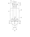
- FIG. 1 is a front view of a pull tab for a slide fastener according to a first embodiment, showing a state in which a box body has been moved to the uppermost position.
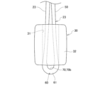
- FIG. 2 is a side view of the pull tab for a slide fastener according to the first embodiment, showing a state in which the box body has been moved to the uppermost position.
- FIG. 3 is a front view of the pull tab for a slide fastener according to the first embodiment, showing a state in which the box body has been moved all the way down.
- FIG. 4 is a side view of the pull tab for the slide fastener according to the first embodiment, showing the state in which the box body has been moved all the way down.
- FIG. 5 is an enlarged view of the lower part of FIG. FIG.
- FIG. 6 is a cross-sectional view taken along line VI-VI in FIG.
- FIG. 7 is a perspective view of the tape.
- FIG. 8 is a side view of the tape.
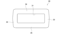
- FIG. 9 is a perspective view of the box.
- FIG. 10 is a plan view of the box as viewed from above and below.
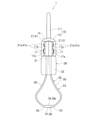
- FIG. 11 is a front view of the pull tab for a slide fastener according to the second embodiment, showing the state in which the box body has been moved to the uppermost position.
- FIG. 12 is a side view of the pull tab for a slide fastener according to the second embodiment, showing the state in which the box body has been moved to the uppermost position.
- FIG. 11 is a front view of the pull tab for a slide fastener according to the second embodiment, showing the state in which the box body has been moved to the uppermost position.
- FIG. 12 is a side view of the pull tab for a slide fastener according to the second embodiment, showing the state in which the box body has been moved to
- FIG. 13 is a front view of the pull tab for a slide fastener according to the second embodiment, showing the state in which the box body has been moved all the way down.
- FIG. 14 is a side view of the pull tab for a slide fastener according to the second embodiment, showing the state in which the box body has been moved all the way down.
- FIG. 15 is an enlarged view of the lower part of FIG.
- FIG. 16 is a cross-sectional view taken along line XVI-XVI in FIG.
- FIG. 17 is an enlarged view of the lower part of FIG.
- FIG. 18 is a perspective view of the tape.
- FIG. 1 is a front view of the pull tab for a slide fastener according to the first embodiment, showing a state where the box body has been moved to the uppermost position.
- FIG. 2 is a side view of the pull tab for a slide fastener according to the first embodiment, showing a state where the box body has been moved to the uppermost position.
- FIG. 3 is a front view of the pull tab for a slide fastener according to the first embodiment, showing a state where the box body has been moved to the lowermost position.
- FIG. 4 is a side view of the pull tab for a slide fastener according to the first embodiment, showing a state where the box body has been moved to the lowermost position.
- FIG. 5 is an enlarged view of the lower portion of FIG. 4.
- FIG. 6 is a cross-sectional view taken along line VI-VI in FIG. 1.
- the "vertical direction” corresponds to the vertical direction in Figs. 1 to 6 and is the longitudinal direction of the slide fastener pull tab 1.
- the "upper side” corresponds to the upper side in Figs. 1 to 6 and is the side closer to the slider to which the slide fastener pull tab 1 is attached.
- the “lower side” corresponds to the lower side in Figs. 1 to 6 and is the side farther from the slider to which the slide fastener pull tab 1 is attached.
- the "thickness direction” corresponds to the left-right direction in Figs. 2 and 4 to 6 and refers to the thickness direction of the slide fastener pull tab 1.
- the "front-rear direction” refers to the front-rear direction of the tape 20 constituting the slide fastener pull tab 1.
- the "left-right direction” corresponds to the left-right direction in Figs. 1 and 3 and is the direction perpendicular to the "up-down direction” and the "thickness direction”, and can also be said to be the width direction of the slide fastener pull tab 1 and the tape 20.
- the pull tab 1 for a slide fastener of this embodiment has a slider attachment part 10 that is attached to a slider (not shown), a tape 20 that is folded in half and has both ends 21, 21 fixed to the slider attachment part 10 to form a ring-shaped part 23, and a box body 30 that serves as a movable part attached to the tape 20 so that it can move up and down.
- the slider attachment part 10 has a slider fixing part 11 arranged on the upper side and fixed to the slider, and a tape fixing part 13 arranged on the lower side and fixed to both ends 21, 21 of the tape 20.
- the slider attachment part 10 is made of, for example, metal or resin, but the material is not particularly limited.
- the slider fixing part 11 and the tape fixing part 13 are formed integrally.
- the slider fixing part 11 is generally annular when viewed from the front as shown in Figs. 1 and 3, and a slider (not shown) can be fixed to its central hole 11a.
- the slide fastener that constitutes the slider has, for example, a plurality of elements arranged in two rows that mesh with each other, and a slider that slides on the elements along the element rows to mesh and release the pair of element rows.
- the slider attachment part 10 may be fixed to an existing pull tab attached to the slider, or the slider attachment part 10 may be fixed to the main body of the slider to which no existing pull tab is attached.
- the tape fixing part 13 is generally inverted U-shaped with an opening on the bottom when viewed from the side.
- the tape fixing part 13 also has openings on both the left and right sides (both sides in the depth direction of the paper in Figures 2, 4, and 6). Both ends 21, 21 of the tape 20 are inserted and fixed inside the tape fixing part 13 through these openings.
- the tape fixing part 13 has the slider fixing part 11 connected to the upper part of the center in the thickness direction (left-right direction in Figures 2, 4 and 6), a base 15 that slopes downward from the center toward both sides in the thickness direction, and a pair of legs 17, 17 that extend downward from both ends of the base 15 in the thickness direction.
- the pair of legs 17, 17 face each other at a distance in the thickness direction (left-right direction in Figs. 2, 4, and 6), and a space is formed between the pair of legs 17, 17 to receive both ends 21, 21 of the tape 20.
- a plurality of protrusions 17a, 17a are formed on the inner surfaces of the pair of legs 17, 17 that face each other and protrude toward the other leg 17.
- the multiple protrusions 17a, 17a are formed in two places, at the tip (lower end) of the leg 17 and at the vertical middle of the leg 17, but the number and shape of the protrusions 17a are not particularly limited.
- the multiple protrusions 17a engage with the protrusions 21a provided on both ends 21, 21 of the tape 20, as described below, thereby fixing the tape fixing part 13 and the tape 20.
- FIG. 7 is a perspective view of the tape.
- FIG. 8 is a side view of the tape.
- the tape 20 is a long member, and is made of a member that has elasticity so that it can be bent.
- the material of the tape 20 is not particularly limited as long as it has elasticity, and resin materials, rubber materials, etc. can be used, and specifically, thermoplastic resins such as Hytrel (registered trademark) can be used.
- the tape 20 has a first tape portion 40, one longitudinal end 41 of which is fixed to the slider attachment portion 10, a second tape portion 50, one longitudinal end 51 of which is fixed to the slider attachment portion 10, a connecting portion 60 that connects the other end 43 of the first tape portion 40 and the other end 53 of the second tape portion 50, and a protrusion 70 formed on the connecting portion 60 and protruding from at least one of the front and back sides of the tape 20.
- the first tape portion 40, the second tape portion 50, the connecting portion 60, and the protrusion 70 are integrally formed. Note that the upper side in Figures 7 and 8 is the back side of the tape 20, and the lower side in Figures 7 and 8 is the front side of the tape 20.
- first tape portion 40 and the second tape portion 50 are mirror-symmetrical with respect to the connecting portion 60 to which they are connected.
- the first tape portion 40 and the second tape portion 50 do not necessarily have to be mirror-symmetrical.
- the ends 41, 51 of the first tape portion 40 and the second tape portion 50 are the ends 21, 21 of the tape 20.
- the surfaces (the undersides of Figures 7 and 8) of the ends 41, 51 of the first tape portion 40 and the second tape portion 50 each have a plurality of protrusions 41a, 51a that protrude toward the surface side.
- the plurality of protrusions 41a, 51a are formed at two locations, the tip of the ends 41, 51 and the middle of the ends 41, 51, but the number and shape of the protrusions 41a, 51a are not particularly limited.
- These protrusions 41a, 51a can also be called the protrusions 21a, 21a of the ends 21 of the tape 20.
- the protrusions 41a, 51a engage with the protrusions 17a of the slider mounting portion 10.
- the back surfaces of the ends 41, 51 of the first tape portion 40 and the second tape portion 50 are generally flat and do not have any protrusions, and can be overlapped with each other as shown in Figures 2, 4, and 6.
- the connecting portion 60 is a portion that connects the first tape portion 40 and the second tape portion 50, and is located approximately in the center of the tape 20 in the longitudinal direction. Note that in this specification, the connecting portion 60 does not mean a single point that connects the first tape portion 40 and the second tape portion 50, but a portion that has a certain distance in the longitudinal direction of the tape 20. And in the connecting portion 60 that has a certain distance in the longitudinal direction, the first convex portion 71 and the second convex portion 73 that make up the convex portion 70 are provided spaced apart from each other.
- the tape 20 is folded in half at the center in the longitudinal direction. That is, the tape 20 is folded back at the portion of the connecting portion 60 between the first convex portion 71 and the second convex portion 73, which are spaced apart from each other. This folded back portion of the connecting portion 60 is called the fold back portion 61.
- the first convex portion 71 and the second convex portion 73 are spaced apart from the fold back portion 61 by equal distances on both sides in the longitudinal direction.
- the convex portion 70 in this embodiment has a first convex portion 71 and a second convex portion 73 that are spaced apart from each other in the longitudinal direction of the tape 20.
- the first convex portion 71 is formed on the other end portion 43 that constitutes the connecting portion 60 of the first tape portion 40, and protrudes to at least one of the front side and the back side of the first tape portion 40.
- the second convex portion 73 is formed on the other end portion 53 that constitutes the connecting portion 60 of the second tape portion 50, and protrudes to at least one of the front side and the back side of the second tape portion 50.
- the first convex portion 71 has a first front-side convex portion 71a and a first back-side convex portion 71b that protrude from the front and back sides of the first tape portion 40
- the second convex portion 73 has a second front-side convex portion 73a and a second back-side convex portion 73b that protrude from the front and back sides of the second tape portion 50.
- the first front-side convex portion 71a and the second front-side convex portion 73a are formed on the outer periphery of the annular portion 23 when the tape 20 is folded in half at the fold-back portion 61, and the first back-side convex portion 71b and the second back-side convex portion 73b are formed on the inner periphery of the annular portion 23 when the tape 20 is folded in half.
- the length of the first backside convex portion 71b is approximately equal to the length of the first frontside convex portion 71a
- the length of the second backside convex portion 73b is approximately equal to the length of the second frontside convex portion 73a.
- the height H2 of the first backside convex portion 71b is smaller than the height H1 of the first frontside convex portion 71a (H2 ⁇ H1)
- the height H3 of the second backside convex portion 73b is smaller than the height H4 of the second frontside convex portion 73a (H4 ⁇ H3).
- FIG. 9 is a perspective view of the box.
- FIG. 10 is a plan view of the box as viewed from above and below.
- the box 30 has a generally rectangular parallelepiped shape.
- the box 30 is made of, for example, a metal material or a resin material, but the material is not particularly limited.
- the box 30 has, at its center, a through hole 31 with a generally rectangular cross section that passes through the box 30 in the up-down direction. Therefore, the box 30 has four faces around the through hole 31.
- the box 30 has a first left-right face 32 and a second left-right face 33 that are arranged at a distance from each other in the left-right direction, and a first thickness face 34 and a second thickness face 35 that are arranged at a distance from each other in the thickness direction.
- the first tape portion 40 and the second tape portion 50 of the tape 20 folded in half are inserted into the through hole 31 in a state where they overlap in the front-back direction of the tape 20 (the depth direction of the paper in Figs. 1 and 3; the left-right direction in Figs. 2, 4 to 6). Therefore, the dimensions of the through hole 31 must be set so that the first tape portion 40 and the second tape portion 50 can be inserted. Therefore, as shown in Figs. 1 and 3, the left-right width of the through hole 31 is set to be larger than the left-right width of the tape 20 (the first tape portion 40 and the second tape portion 50). Also, as shown in Fig.
- the height h1 of the through hole 31 in the front-back direction of the tape 20 is set to be larger than the total height H5+H6 of the height H5 of the first tape portion 40 and the height H6 of the second tape portion 50 (h1>H5+H6).
- the ends 41, 51 of the first tape portion 40 and the second tape portion 50 above the through hole 31 are inserted into the receiving space between the pair of legs 17, 17 of the tape fixing portion 13, with the flat portions of the backsides of the ends 41, 51 overlapping each other.
- the ends are inserted into the receiving space from an opening in the left-right direction of the tape fixing portion 13 (left-right direction in Figs. 1 and 3; depth direction on the paper in Figs. 2, 4 to 6).
- the pair of legs 17, 17 are tightened in a direction that brings them closer to each other. This engages the multiple protrusions 17a, 17a of the pair of legs 17, 17 with the protrusions 41a, 51a on the ends 41, 51, and fixes the tape fixing portion 13 and the tape 20.
- the total height H1+H2+H3+H4+H5+H6 of the height H5 of the first tape portion 40, the height H1+H2 of the first convex portion 71, the height H6 of the second tape portion 50, and the height H3+H4 of the second convex portion 73 is higher than the height h1 of the through hole 31 of the box body 30 (H1+H2+H3+H4+H5+H6>h1).
- the size of the annular portion 23 of the tape 20 can be changed by moving the box body 30 up and down, allowing each user to use it in a way that suits them.
- the annular part 23 of the tape 20 elastically shrinks in diameter and deforms so as to enter the through hole 31 of the box 30.
- the first tape part 40 and the second tape part 50 constituting the annular part 23 of the tape 20 move closer to each other, and the annular part 23 becomes thinner in the thickness direction (left-right direction in Figs. 4 to 6) and longer in the up-down direction.
- the slide fastener pull tab 1 can be pulled by grasping the tape 20 or the box 30.
- the tape 20 is folded back at the fold-back portion 61, but since the first convex portion 71 and the second convex portion 73 are spaced apart from the fold-back portion 61 by equal distances on both sides in the longitudinal direction, the first convex portion 71 and the second convex portion 73 approach or come into contact with each other.
- Figure 5 shows an example in which the first back-side convex portion 71b of the first convex portion 71 and the second back-side convex portion 73b of the second convex portion 73 face each other with a small gap between them, but when the box body 30 is moved all the way down (towards the connecting portion 60), the first back-side convex portion 71b and the second back-side convex portion 73b may face each other with a gap between them or may come into contact with each other.
- the height H2 of the first back-side convex portion 71b is smaller than the height H1 of the first front-side convex portion 71a (H2 ⁇ H1), and the height H4 of the second back-side convex portion 73b is smaller than the height H3 of the second front-side convex portion 73a (H4 ⁇ H3). Therefore, when the box body 30 is moved all the way toward the connecting portion 60 on the opposite side from the slider attachment portion 10, the range of the folded portion 61 of the tape 20 between the first convex portion 71 and the second convex portion 73 can be narrowed, so that it can be made closer to a plate shape, giving the impression of being slim.
- the connecting portion 60 elastically deforms so as to be folded, and the first back side convex portion 71b of the first convex portion 71 and the second back side convex portion 73b of the second convex portion come into contact with each other or face each other with a small gap between them. Therefore, the first convex portion 71 and the second convex portion 73 prevent the tape 20 from entering the through hole 31 of the box body 30, and the box body 30 is prevented from falling out downward.
- the total height H1+H2+H3+H4+H5+H6 of the height H5 of the first tape portion 40, the height H1+H2 of the first convex portion 71, the height H6 of the second tape portion 50, and the height H3+H4 of the second convex portion 73 is set to be greater than the height h1 of the through hole 31 of the box body 30 (H1+H2+H3+H4+H5+H6>h1), so that the box body 30 is more reliably prevented from falling out downward.
- FIG. 5 also shows an example in which a vertical gap S exists between the first front-side protrusion 71a of the first protrusion 71 and the second front-side protrusion 73a of the second protrusion 73 and the box body 30. It is desirable to adjust the elasticity and shape of the tape 20 so that the vertical gap S is formed as described above even when the box body 30 is moved all the way down (towards the connecting portion 60). By inserting a user's fingernail into the vertical gap S, it is possible to move the box body 30 upward toward the slider attachment portion 10 without relying on vision.
- slide fastener pull tab 1 according to a second embodiment will be described.
- the slide fastener pull tab 1 of this embodiment differs from the first embodiment only in the configuration of the protrusion 70, and other configurations are substantially the same as those of the first embodiment. Therefore, the same parts are denoted by the same reference numerals in the drawings, and the description thereof will be omitted or simplified.
- FIG. 11 is a front view of the pull tab for the slide fastener according to the second embodiment, showing the state where the box body has been moved to the uppermost position.
- FIG. 12 is a side view of the pull tab for the slide fastener according to the second embodiment, showing the state where the box body has been moved to the uppermost position.
- FIG. 13 is a front view of the pull tab for the slide fastener according to the second embodiment, showing the state where the box body has been moved to the lowermost position.
- FIG. 14 is a side view of the pull tab for the slide fastener according to the second embodiment, showing the state where the box body has been moved to the lowermost position.
- FIG. 15 is an enlarged view of the lower portion of FIG. 14.
- FIG. 16 is a cross-sectional view taken along line XVI-XVI in FIG. 11.
- FIG. 17 is an enlarged view of the lower portion of FIG. 16.
- FIG. 18 is a perspective view of the tape.
- the tape 20 of this embodiment like the first embodiment, has a protrusion 70 formed at the connecting portion 60 and protruding from at least one of the front and back sides of the tape 20.
- the protrusion 70 of this embodiment does not have a first protrusion 71 and a second protrusion 73, but consists of a single back side protrusion 70b.
- the first convex portion 71 and the second convex portion 73 are positioned away from the folded portion 61 of the connecting portion 60, so that the tape 20 is easily elastically deformed so as to be easily folded at the folded portion 61 when the box body 30 is moved downward.
- a convex portion 70 (rear side convex portion 70b) is provided at the folded portion 61, so that the tape 20 does not bend significantly at the folded portion 61 when the box body 30 is moved downward, and the connecting portion 60 including the folded portion 61 maintains a height that does not allow it to enter the through hole 31.
- the protrusion 70 has the function of restricting bending at the folded portion 61, it may have only a back-side protrusion 70b that protrudes to the back side, may have only a front-side protrusion that protrudes to the front side, or may have both a back-side protrusion and a front-side protrusion.
- a recess (not shown) that can fit with the protrusion 70 of the tape 20 may be provided on the lower part of the box 30 on the connecting part 60 side.
- the protrusion 70 and the recess can fit together to restrict the movement of the box 30 towards the connecting part 60 side, so that the box 30 can be more reliably prevented from falling out downward.
- a slider attachment portion (10) that is attached to a slider; a tape (20) folded in half, both ends of which are fixed to the slider attachment portion (10) to form a loop; a moving part (30) attached to the tape (20) so as to be movable up and down;
- a pull tab (1) for a slide fastener comprising:
- the tape (20) is a first tape portion (40) having one end (41) fixed to the slider attachment portion (10); a second tape portion (50) having one end (51) fixed to the slider attachment portion (10); a connecting portion (60) that connects the other end (43) of the first tape portion (40) and the other end (53) of the second tape portion (50);
- the moving part (30) has a through hole (31) penetrating the moving part (30), and is movable up and down on the tape (20) with the first tape part (40) and the second
- a movable part (30) is provided that can move up and down on the tape (20) with the first tape part (40) and the second tape part (50) inserted into the through hole (31), so that by moving the movable part (30), the size of the annular part of the tape (20) can be changed, allowing for usage that is suitable for each user.
- the moving part (30) is moved to the slider attachment part (10) side, the loop part of the tape (20) becomes the largest, so that the user can hook the finger on the loop part and use it. Therefore, even a user with a disability in his/her hands or a user wearing gloves can easily pull the pull tab (1).
- the annular part of the tape (20) becomes smaller, and the grippable part of the tape (20) can be lengthened.
- the pull tab (1) can be pulled by gripping the tape (20) or the moving part (30).
- a protrusion (70) is formed on the tape (20) at the connecting portion (60) on the opposite side to the slider attachment portion (10). Therefore, for example, if the part of the tape (20) on which the convex portion (70) is formed is made to a height such that it cannot enter the through hole (31) of the moving part (30), it is possible to prevent the moving part (30) from falling out from the connecting part (60) side.
- the connecting part (60) is prevented from bending too much, and the connecting part (60) is kept at a height that prevents it from entering the through-hole (31) of the moving part (30). In this case as well, it is possible to prevent the moving part (30) from falling out from the connecting part (60).
- the convex portion (70) has a first convex portion (71) and a second convex portion (73) spaced apart from each other,
- the first convex portion (71) is formed on the other end portion (43) of the first tape portion (40) and protrudes toward at least one of the front side and the back side of the first tape portion (40)
- the second convex portion (73) is formed on the other end portion (53) of the second tape portion (50) and protrudes toward at least one of the front side and the back side of the second tape portion (50).
- the pull tab (1) for a slide fastener according to [1].
- the first convex portion (71) has a first front side convex portion (71a) and a first back side convex portion (71b) protruding from the front side and the back side of the first tape portion (40),
- the second convex portion (73) has a second front side convex portion (73a) and a second back side convex portion (73b) which protrude from the front side and the back side of the second tape portion (50).
- the pull tab (1) for a slide fastener according to [2].
- the connecting portion (60) elastically deforms so as to be folded, and the first back side convex portion (71b) of the first convex portion (71) and the second back side convex portion (73b) of the second convex portion (73) come into contact with each other or face each other with a small gap between them. Therefore, the first convex portion (71) and the second convex portion (73) prevent the tape (20) from entering the through hole (31) of the moving portion (30), thereby preventing the moving portion (30) from falling off.
- a height (H2) of the first back-side convex portion (71b) is smaller than a height (H1) of the first front-side convex portion (71a), and a height (H4) of the second back-side convex portion (73b) is smaller than a height (H3) of the second front-side convex portion (73a).
- the pull tab (1) for a slide fastener according to [3].
- the first convex portion (71) and the second convex portion (73) more reliably prevent the tape (20) from entering the through hole (31) of the moving portion (30), so that the moving portion (30) is more reliably prevented from falling out.
- the connecting portion (60) includes a folded portion (61) which is a portion that is folded when the tape (20) is folded in half,
- the folded portion (61) is provided with the convex portion (70) that protrudes from at least one of the front side and the back side of the tape (20).
- the folded portion (61) becomes thicker due to the provision of the convex portion (70), so the amount of elastic deformation is reduced and it becomes less likely to bend.
Landscapes
- Slide Fasteners (AREA)
- Package Frames And Binding Bands (AREA)
- Buckles (AREA)
Priority Applications (5)
| Application Number | Priority Date | Filing Date | Title |
|---|---|---|---|
| DE112023006118.1T DE112023006118T5 (de) | 2023-03-31 | 2023-03-31 | Reissverschlusszug |
| JP2025509650A JP7820610B2 (ja) | 2023-03-31 | 2023-03-31 | スライドファスナー用引手 |
| PCT/JP2023/013747 WO2024202073A1 (ja) | 2023-03-31 | 2023-03-31 | スライドファスナー用引手 |
| CN202410260000.9A CN118716742A (zh) | 2023-03-31 | 2024-03-07 | 拉链用拉片 |
| CN202420439508.0U CN222171466U (zh) | 2023-03-31 | 2024-03-07 | 拉链用拉片 |
Applications Claiming Priority (1)
| Application Number | Priority Date | Filing Date | Title |
|---|---|---|---|
| PCT/JP2023/013747 WO2024202073A1 (ja) | 2023-03-31 | 2023-03-31 | スライドファスナー用引手 |
Publications (1)
| Publication Number | Publication Date |
|---|---|
| WO2024202073A1 true WO2024202073A1 (ja) | 2024-10-03 |
Family
ID=92849990
Family Applications (1)
| Application Number | Title | Priority Date | Filing Date |
|---|---|---|---|
| PCT/JP2023/013747 Ceased WO2024202073A1 (ja) | 2023-03-31 | 2023-03-31 | スライドファスナー用引手 |
Country Status (4)
| Country | Link |
|---|---|
| JP (1) | JP7820610B2 (https=) |
| CN (2) | CN118716742A (https=) |
| DE (1) | DE112023006118T5 (https=) |
| WO (1) | WO2024202073A1 (https=) |
Citations (7)
| Publication number | Priority date | Publication date | Assignee | Title |
|---|---|---|---|---|
| JPS5745315U (https=) * | 1980-08-28 | 1982-03-12 | ||
| JP2002017411A (ja) * | 2000-06-23 | 2002-01-22 | Illinois Tool Works Inc <Itw> | ジッパコード止め具 |
| JP2002112826A (ja) * | 2000-10-12 | 2002-04-16 | Sanwa Kk | 携帯品用ストラップ |
| JP2006043095A (ja) * | 2004-08-04 | 2006-02-16 | Morito Co Ltd | スライダーの引手延長具 |
| JP2015033514A (ja) * | 2013-08-09 | 2015-02-19 | Ykk株式会社 | 意匠部材、引手、ボタン、及び意匠部材の製造方法 |
| JP2015096183A (ja) * | 2013-11-17 | 2015-05-21 | 進 中谷 | 落下防止物品付き携帯ストラップ |
| JP2017527317A (ja) * | 2014-07-08 | 2017-09-21 | デュラフレックス ホンコン リミテッド | プルタブ及びプルタブの製造方法 |
Family Cites Families (3)
| Publication number | Priority date | Publication date | Assignee | Title |
|---|---|---|---|---|
| JP2002065932A (ja) | 2000-08-31 | 2002-03-05 | Kizaki:Kk | スキーストック用ストラップ |
| JP3103203U (ja) | 2004-02-05 | 2004-07-29 | 紀久代 栂 | 携帯品用ストラップ |
| JP3132769U (ja) | 2007-03-30 | 2007-06-21 | 紀久代 栂 | 文字等用装飾体並びに文字等用装飾体を装着した愛玩動物用首輪、携帯品用ストラップおよび広告表示体 |
-
2023
- 2023-03-31 WO PCT/JP2023/013747 patent/WO2024202073A1/ja not_active Ceased
- 2023-03-31 DE DE112023006118.1T patent/DE112023006118T5/de active Pending
- 2023-03-31 JP JP2025509650A patent/JP7820610B2/ja active Active
-
2024
- 2024-03-07 CN CN202410260000.9A patent/CN118716742A/zh active Pending
- 2024-03-07 CN CN202420439508.0U patent/CN222171466U/zh active Active
Patent Citations (7)
| Publication number | Priority date | Publication date | Assignee | Title |
|---|---|---|---|---|
| JPS5745315U (https=) * | 1980-08-28 | 1982-03-12 | ||
| JP2002017411A (ja) * | 2000-06-23 | 2002-01-22 | Illinois Tool Works Inc <Itw> | ジッパコード止め具 |
| JP2002112826A (ja) * | 2000-10-12 | 2002-04-16 | Sanwa Kk | 携帯品用ストラップ |
| JP2006043095A (ja) * | 2004-08-04 | 2006-02-16 | Morito Co Ltd | スライダーの引手延長具 |
| JP2015033514A (ja) * | 2013-08-09 | 2015-02-19 | Ykk株式会社 | 意匠部材、引手、ボタン、及び意匠部材の製造方法 |
| JP2015096183A (ja) * | 2013-11-17 | 2015-05-21 | 進 中谷 | 落下防止物品付き携帯ストラップ |
| JP2017527317A (ja) * | 2014-07-08 | 2017-09-21 | デュラフレックス ホンコン リミテッド | プルタブ及びプルタブの製造方法 |
Also Published As
| Publication number | Publication date |
|---|---|
| CN222171466U (zh) | 2024-12-17 |
| JP7820610B2 (ja) | 2026-02-25 |
| JPWO2024202073A1 (https=) | 2024-10-03 |
| DE112023006118T5 (de) | 2026-02-19 |
| CN118716742A (zh) | 2024-10-01 |
Similar Documents
| Publication | Publication Date | Title |
|---|---|---|
| US11612199B2 (en) | Touch protector | |
| JP5347150B2 (ja) | 留め具 | |
| JP4795541B2 (ja) | ファスナー | |
| US9468781B2 (en) | Fastening device for straps | |
| EP1750535A1 (en) | Locking zipper pull | |
| EP2340733A2 (en) | Buckling device | |
| KR20170012361A (ko) | 개인용 보호 장치 스트랩 연결 버클 조립체 | |
| WO2024202073A1 (ja) | スライドファスナー用引手 | |
| CN218354916U (zh) | 一种防拉片卡死的拉链头及拉链 | |
| US6925687B1 (en) | Bib napkin holding clip | |
| CN110811084B (zh) | 拉片辅助器具、拉片以及拉链拉头 | |
| WO2017063195A1 (zh) | 扣具 | |
| CN107567290A (zh) | 可逆连接器件 | |
| US20190224453A1 (en) | Retention member for securing a catheter on a patient | |
| KR102648428B1 (ko) | 치열 교정 브라켓 | |
| CN210158412U (zh) | 颈枕及其磁吸组件 | |
| US9259043B2 (en) | Flexible fastener for removable attachment to fabric | |
| WO2007119979A1 (en) | Binding tool | |
| US20170135446A1 (en) | Interchangeable zipper grip | |
| JP4789038B2 (ja) | 顔面装着具および顔面装着具用バンド | |
| JP2003135108A (ja) | ウエストサイズ調節具 | |
| WO2005030001A1 (en) | Shoulder strap carrier arrangement | |
| CN213346343U (zh) | 烧伤病人的指蹼疤痕压力治疗装置 | |
| JP2007301236A (ja) | 装身具用留め具 | |
| CN101636313A (zh) | 呼吸管夹 |
Legal Events
| Date | Code | Title | Description |
|---|---|---|---|
| 121 | Ep: the epo has been informed by wipo that ep was designated in this application |
Ref document number: 23930707 Country of ref document: EP Kind code of ref document: A1 |
|
| WWE | Wipo information: entry into national phase |
Ref document number: 2025509650 Country of ref document: JP |
|
| WWE | Wipo information: entry into national phase |
Ref document number: 112023006118 Country of ref document: DE |
|
| WWP | Wipo information: published in national office |
Ref document number: 112023006118 Country of ref document: DE |
|
| 122 | Ep: pct application non-entry in european phase |
Ref document number: 23930707 Country of ref document: EP Kind code of ref document: A1 |