WO2024201874A1 - 車両構造 - Google Patents
車両構造 Download PDFInfo
- Publication number
- WO2024201874A1 WO2024201874A1 PCT/JP2023/013099 JP2023013099W WO2024201874A1 WO 2024201874 A1 WO2024201874 A1 WO 2024201874A1 JP 2023013099 W JP2023013099 W JP 2023013099W WO 2024201874 A1 WO2024201874 A1 WO 2024201874A1
- Authority
- WO
- WIPO (PCT)
- Prior art keywords
- vehicle
- reinforcement
- cross member
- floor panel
- surface portion
- Prior art date
- Legal status (The legal status is an assumption and is not a legal conclusion. Google has not performed a legal analysis and makes no representation as to the accuracy of the status listed.)
- Ceased
Links
Images





Classifications
-
- B—PERFORMING OPERATIONS; TRANSPORTING
- B62—LAND VEHICLES FOR TRAVELLING OTHERWISE THAN ON RAILS
- B62D—MOTOR VEHICLES; TRAILERS
- B62D33/00—Superstructures for load-carrying vehicles
- B62D33/02—Platforms; Open load compartments
Definitions
- the present invention relates to a vehicle structure.
- Patent Document 1 shows a truck bed floor structure in which a floor panel is laid on a floor frame having multiple cross members and a rear cross member erected between a pair of left and right side members extending in the fore-and-aft direction, and the floor is placed on a pair of left and right chassis frames extending in the fore-and-aft direction.
- the rear cross member at the very back and the cross member with the mounting bracket just before it are joined in the fore-and-aft direction by reinforcements and are fixed to the outriggers of the chassis frame, preventing deformation of the bed floor due to the forward inertial force when the vehicle is suddenly braked.
- the present invention aims to provide a vehicle structure with a highly durable cargo bed.
- the present invention comprises the following configurations.
- a floor panel that constitutes a central portion in a vehicle width direction at a bottom of a cargo bed of the vehicle; side panels connected to both ends of the floor panel in the vehicle width direction to define both ends of the bottom of the loading platform in the vehicle width direction;
- a reinforcement is joined to the floor panel and the side panel across a connection portion between the floor panel and the side panel, A cross member extending in the vehicle width direction along the bottom of the loading platform, and both ends of the cross member being joined to the floor panel, the side panel, and the reinforcement, respectively, across the connection portion; Equipped with Vehicle structure.
- the present invention provides a vehicle structure with a highly durable cargo bed.
- FIG. 1 is a side view of a vehicle to which the vehicle structure of the present invention is applied.
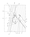
- FIG. 2 is a perspective view of the bottom of the loading platform as viewed from below.
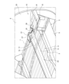
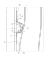
- FIG. 3 is a side view of the attachment points of the reinforcement and the cross member at the bottom of the cargo bed.
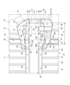
- FIG. 4 is a bottom view showing the attachment locations of the reinforcement and the cross member at the bottom of the cargo bed.
- FIG. 5 is a perspective view of the bottom of the cargo bed, showing the cargo bed, the reinforcement, and the cross member, as viewed from below.
- FIG. 6A is a bottom view of the reinforcement.
- FIG. 6B is a view taken along the arrow A in FIG. 6A.
- FIG. 6C is a view taken along the arrow B in FIG. 6A.
- FIG. 6A is a bottom view of the reinforcement.
- FIG. 6B is a view taken along the arrow A in FIG. 6A.
- FIG. 6C is a view taken along the arrow B
- FIG. 6D is a view taken along the arrow C in FIG. 6A.
- FIG. 7A is a bottom view of the cross member.
- FIG. 7B is a view taken along the arrow D in FIG. 7A.
- FIG. 7C is a view taken along the arrow E in FIG. 7A.
- FIG. 1 is a side view of a vehicle 100 to which the vehicle structure of the present invention is applied.
- vehicle structure according to this embodiment is applied to a vehicle 100, which is, for example, a small truck such as a pickup truck.
- vehicle 100 includes a cab 1 in which an occupant sits, and a cargo bed 3 provided behind the cab 1.
- vehicle 100 includes a chassis frame (frame) 5, and the cab 1 and the cargo bed 3 are supported by the chassis frame 5.
- Fig. 2 is a perspective view of the bottom 15 of the cargo bed 3 as viewed from below.
- Fig. 3 is a side view of the attachment locations of the bottom 15 of the cargo bed 3 to which the reinforcement 21 and the cross member 23 are attached.
- the chassis frame 5 is composed of side frames 7 and cross members 9.
- the chassis frame 5 has a pair of side frames 7 that extend in the front-rear direction of the vehicle with a gap in the vehicle width direction.
- the chassis frame 5 also has a plurality of cross members 9 that extend in the vehicle width direction at a plurality of locations that are spaced apart in the vehicle front-rear direction and are connected to the pair of side frames 7.
- the cargo bed 3 is positioned above the side frames 7.
- the cargo bed 3 includes a floor panel 11 and side panels 13.
- the floor panel 11 forms the center of the bottom 15 of the cargo bed 3 in the vehicle width direction.
- the side panels 13 are provided on both sides of the floor panel 11 in the vehicle width direction.
- the side panels 13 form both ends of the bottom 15 of the cargo bed 3 in the vehicle width direction and both sides of the cargo bed 3, and also form the wheel house 6 that houses the rear wheels (not shown) (see Figure 1).
- the cargo bed 3 is provided with reinforcing reinforcements 21 and cross members 23. These reinforcements 21 and cross members 23 are provided on the underside of the bottom 15 of the cargo bed 3, and are positioned above the side frames 7 that constitute the chassis frame 5 when viewed from the side of the vehicle.
- the side frames 7 are curved so as to bulge upward inside the wheel house 6. Moreover, because this reinforced location is the rear end of the wheel house 6 in the vehicle's fore-and-aft direction, the side panels 13 protrude outward in the vehicle width direction.
- the positions of both ends of the cross member 23 are positions where it is difficult to reinforce them by, for example, erecting a reinforcing plate on the side frame 7 and connecting both ends of the cross member 23 to this reinforcing plate. Therefore, it is desirable to effectively reinforce both ends of the cross member 23 with the reinforcements 21 and cross members 23.
- Figure 4 is a bottom view showing the attachment points of the reinforcement 21 and the cross member 23 on the bottom 15 of the cargo bed 3.
- Figure 5 is a perspective view of the bottom 15 of the cargo bed 3 from below, showing the cargo bed 3, the reinforcement 21, and the cross member 23.
- the floor panel 11 that constitutes the cargo bed 3 is a plate material with a corrugated cross section, and side panels 13 are connected to both ends of the floor panel 11 in the vehicle width direction.
- the side panel 13 has a bottom plate portion 31 and a side plate portion 33 that extends upward from the bottom plate portion 31, and the bottom plate portion 31 has a portion with a corrugated cross section like the floor panel 11.
- the ends of the bottom plate portion 31 of the side panel 13 are connected to the ends of the floor panel 11.
- the floor panel 11 and side panel 13 are joined by spot welding with the end of the bottom plate portion 31 of the side panel 13 overlapping the upper surface side of the end of the floor panel 11 (joint P1 in Figure 4).
- a connection portion 35 between the floor panel 11 and the side panel 13 is provided on the bottom 15 of the cargo bed 3 along the fore-and-aft direction of the vehicle.
- the two members, the floor panel 11 and the side panel 13 are spot welded (two-piece welding) with the two members overlapping.
- the end of the floor panel 11 may also be overlapped on the upper surface side of the end of the bottom plate portion 31 of the side panel 13 and joined by spot welding.
- the bottom 15 of the loading platform 3 is made up of a floor panel 11 with a corrugated cross section and a bottom plate portion 31 of a side panel 13.
- the bottom 15 of the loading platform 3 has a corrugated cross section with convex portions 41 and concave portions 43 formed alternately in the vehicle width direction.
- the connection portion 35 is a convex portion 41, and a concave portion 43 is provided on both sides of this connection portion 35. It is also possible that in the bottom 15 of the loading platform 3, the connection portion 35 is a concave portion 43, and a convex portion 41 is provided on both sides of this connection portion 35.
- the rigidity of the bottom 15 of the loading platform 3 is increased by the convex portions 41 and concave portions 43 that are alternately formed in the vehicle width direction.
- the convex portions 41 and concave portions 43 are formed along the vehicle front-rear direction, the bending strength of the bottom 15 of the loading platform 3 in the vehicle front-rear direction is increased.
- the bottom 15 of the cargo bed 3 configured as above has reinforcements 21 and cross members 23 provided in this order from the underside.
- the reinforcements 21 and cross members 23 are formed by pressing steel plates. These reinforcements 21 and cross members 23 are joined to the floor panel 11 and the side panel 13, respectively, in a state in which they are positioned across the connection portion 35 between the floor panel 11 and the side panel 13 at the bottom 15 of the cargo bed 3.
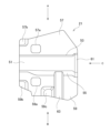
- FIG. 6A is a bottom view of the reinforcement 21.
- FIG. 6B is a view seen from the direction of arrow A in FIG. 6A.
- FIG. 6C is a view seen from the direction of arrow B in FIG. 6A.
- FIG. 6D is a view seen from the direction of arrow C in FIG. 6A.
- the reinforcement 21 has a first bottom surface portion 51, a first front side surface portion 53, a first rear side surface portion 55, a first front flange portion 57, and a first rear flange portion 59.
- the first front side portion 53 extends upward from the edge of the first bottom portion 51 on the front side in the vehicle fore-and-aft direction
- the first rear side portion 55 extends upward from the edge of the first bottom portion 51 on the rear side in the vehicle fore-and-aft direction
- the first front flange portion 57 extends forward in the vehicle fore-and-aft direction from the upper edge of the first front side portion 53
- the first rear flange portion 59 extends rearward in the vehicle fore-and-aft direction from the upper edge of the first rear side portion 55.
- the reinforcement 21 is applied to the bottom 15 of the cargo bed 3 from the first front flange portion 57 and the first rear flange portion 59, with the first front flange portion 57 facing forward in the vehicle's fore-and-aft direction and the first rear flange portion 59 facing rearward in the vehicle's fore-and-aft direction.
- the reinforcement 21 is then positioned across the connection portion 35 at the bottom 15 of the cargo bed 3 and joined to the floor panel 11 and the side panel 13.
- the reinforcement 21 has openings 57a, 59a in the first front flange portion 57 and the first rear flange portion 59, respectively. These openings 57a, 59a are formed in positions that overlap with the connection portion 35 when the reinforcement 21 is joined to the bottom portion 15 of the loading platform 3.
- the reinforcement 21 has a protrusion 57b on the first front flange portion 57, and protrusions 59b, 59c on the first rear flange portion 59.
- the protrusions 57b, 59b of the first front flange portion 57 and the first rear flange portion 59 are positioned at the position of the recess 43 on the floor panel 11 side adjacent to the connection portion 35 when the reinforcement 21 is joined to the bottom 15 of the cargo bed 3.
- the protrusion 59c of the first rear flange portion 59 is positioned at the position of the recess 43 on the side panel 13 side adjacent to the connection portion 35 when the reinforcement 21 is joined to the bottom 15 of the cargo bed 3.
- the reinforcement 21 also has a bulge 61 at the outer end in the vehicle width direction, where the concave portion consisting of the first bottom surface portion 51, the first front flange portion 57, and the first rear flange portion 59 is enlarged in diameter, and this bulge 61 increases the rigidity of the end of the reinforcement 21. More specifically, the bulge 61 is formed by the first bottom surface portion 51, the first rear side surface portion 55, and the first rear flange portion 59. Therefore, the bulge 63 increases the rigidity of the reinforcement 21 on the rear side in the vehicle front-rear direction.
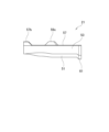
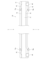
- FIG. 7A is a bottom view of the cross member 23.
- FIG. 7B is a view seen from the arrow D in FIG. 7A.
- FIG. 7C is a view seen from the arrow E in FIG. 7A.
- the cross member 23 has a second bottom surface portion 71, a second front side surface portion 73, a second rear side surface portion 75, a second front flange portion 77, and a second rear flange portion 79.
- This cross member 23 has an elongated shape that extends in the vehicle width direction.
- the second front side portion 73 extends upward from the front edge of the second bottom portion 71 in the vehicle fore-and-aft direction
- the second rear side portion 75 extends upward from the rear edge of the second bottom portion 71 in the vehicle fore-and-aft direction
- the second front flange portion 77 extends forward in the vehicle fore-and-aft direction from the upper edge of the second front side portion 73
- the second rear flange portion 79 extends rearward in the vehicle fore-and-aft direction from the upper edge of the second rear side portion 75.
- the cross member 23 is positioned along the vehicle width direction with the second front flange portion 77 facing forward in the vehicle longitudinal direction and the second rear flange portion 79 facing rearward in the vehicle longitudinal direction relative to the bottom 15 of the cargo bed 3, and is joined to the floor panel 11 and the side panel 13 from the second front flange portion 77 and the second rear flange portion 79 sides. Both ends of the cross member 23 are joined to the bottom 15 of the cargo bed 3 via reinforcements 21.
- the cross member 23 also has overhangs 77a, 79a at the second front flange 77 and the second rear flange 79, which protrude by the thickness of the first front flange 57 and the first rear flange 59 of the reinforcement 21.
- These overhangs 77a, 79a are formed at positions corresponding to the openings 57a, 59a of the reinforcement 21.
- the cross member 23 has bulges 81 on the second front side surface portion 73 at both ends, which increase the rigidity of the cross member 23 on the front side in the vehicle's fore-and-aft direction.
- the cross member 23 has bulges 83 on the second rear side surface portion 75 and the second rear flange portion 79 at both ends, which extend along the vehicle's fore-and-aft direction, and these bulges 83 increase the rigidity of the cross member 23 on the rear side in the vehicle's fore-and-aft direction.
- the reinforcement 21 is placed on the attachment side to the bottom 15 at both ends of the cross member 23, and they are joined together by spot welding. Specifically, the overlapping area between the first bottom surface portion 51 of the reinforcement 21 and the second bottom surface portion 71 of the cross member 23 is spot welded. The overlapping area between the first front flange portion 57 of the reinforcement 21 and the second front flange portion 77 of the cross member 23 is also spot welded. The overlapping area between the first rear flange portion 59 of the reinforcement 21 and the second rear flange portion 79 of the cross member 23 is also spot welded (joint point P2 in FIG. 4).
- the reinforcement 21 is spot welded at the overlapping points between the first front flange portion 57 and the first rear flange portion 59 and the floor panel 11 and the side panel 13 (joint P3 in FIG. 4). At this joint P3, the two members, the reinforcement 21 and the floor panel 11 or the reinforcement 21 and the side panel 13, are spot welded (two-piece welding) in an overlapping state.
- the protrusions 57b, 59b of the first front flange portion 57 and the first rear flange portion 59 are positioned at the position of the recess 43 on the floor panel 11 side adjacent to the connection portion 35, and contact the bottom surface of the recess 43.
- the protrusion 59c of the first rear flange portion 59 is positioned at the position of the recess 43 on the side panel 13 side adjacent to the connection portion 35, and contact the bottom surface of the recess 43. Therefore, these protrusions 57b, 59b, 59c can be smoothly spot welded to the bottom 15 of the cargo bed 3.
- the overlapping areas of the first front flange portion 57 and the first rear flange portion 59 and the connection portion 35 are spot welded (joint P4 in FIG. 4).
- the three members of the reinforcement 21, the floor panel 11, and the side panel 13 are spot welded (three-piece welding) in an overlapping state.
- the cross member 23 is spot welded where the second front flange portion 77 and the second rear flange portion 79 overlap with the floor panel 11 (joint P5 in FIG. 4). At this joint P5, the cross member 23 and the floor panel 11 are spot welded (two-piece welding) while the two members are overlapped.
- the overlapping areas of the second front flange portion 77 and the second rear flange portion 79 and the connection portion 35 are spot welded (joint P6 in FIG. 4).
- the three members, the cross member 23, the floor panel 11, and the side panel 13, are spot welded (three-piece welding) in an overlapping state.
- the protruding portions 77a, 79a of the second front flange portion 77 and the second rear flange portion 79 contact the connection portion 35 through the openings 57a, 59a of the reinforcement 21. Therefore, the second front flange portion 77 and the second rear flange portion 79 can be smoothly spot welded to the connection portion 35 of the bottom 15 of the cargo bed 3.
- the cross member 23 is spot welded to the side panel 13 at the overlapping points between the second front flange portion 77 and the second rear flange portion 79 and the first front flange portion 57 and the first rear flange portion 59 of the reinforcement 21 (joint P7 in FIG. 4). At this joint P7, the three members of the cross member 23, the reinforcement 21, and the side panel 13 are spot welded (three-piece welding) in an overlapping state.
- connection parts 35 provided on the left and right sides of the bottom 15 of the cargo bed 3, these connection parts 35 can be effectively reinforced.
- the rigidity of the connection 35 between the floor panel 11 and the side panel 13 and the joints at both ends of the cross member 23, which are easily subjected to load, can be increased and strengthened by the reinforcement 21. This makes it possible to suppress damage and peeling off at both ends of the cross member 23 associated with twisting of the bottom 15 of the cargo bed 3, which occurs when driving on rough roads, etc. In particular, since it is possible to strengthen the areas around both ends of the cross member 23, which are subjected to load when the cargo bed 3 twists, peeling off of the connection 35 and both ends of the cross member 23 can be suppressed.
- the reinforcement 21 is made wider in the vehicle fore-and-aft direction than the cross member 23.
- the first front flange portion 57 and the first rear flange portion 59 of the reinforcement 21 protrude outward in the vehicle fore-and-aft direction from the second front flange portion 77 and the second rear flange portion 79 of the cross member 23.
- These protruding portions are then joined to the floor panel 11 and the side panel 13, respectively, at joint point P2. Therefore, the load caused by twisting of the bottom 15 of the cargo bed 3 can be received and distributed over a wide area in the vehicle fore-and-aft direction.
- connection 35 the three components of the side panel 13, floor panel 11, and reinforcement 21 are spot welded (three-piece welding) in an overlapping state at joint P4, and the three components of the side panel 13, floor panel 11, and cross member 23 are spot welded (three-piece welding) in an overlapping state at joint P6. This makes it possible to uniform the rigidity of the joints at the connection 35.
- both ends of the cross member 23 in the vehicle width direction and the entire reinforcement 21 can follow the deformation of the floor panel 11 and side panel 13, preventing damage or peeling caused by the concentration of load at specific points.
- both ends of the reinforcement 21 and cross member 23 joined to the bottom 15 of the cargo bed 3 are arranged such that the first bottom surface 51 and second bottom surface 71 are close to the top surface 7a of the side frame 7 constituting the chassis frame 5 and are positioned along the top surface 7a of the side frame 7.
- a sheet-like cushioning material (not shown) made of an elastic material such as rubber is provided in the gap between the top surface 7a of the side frame 7 and the second bottom surface 71 of the cross member 23. This allows the reinforcement 21 and cross member 23 to absorb the force transmitted from the side frame 7 to the bottom 15 of the cargo bed 3 when the vehicle is traveling.
- both ends of the reinforcement 21 and the cross member 23 have widened portions 25.
- the reinforcement 21 has a first rear side surface portion 55 that is inclined in a direction gradually moving away from the first front side surface portion 53 from the first bottom surface portion 51 toward the first rear flange portion 59
- the cross member 23 has a second rear side surface portion 75 that is inclined in a direction gradually moving away from the second front side surface portion 73 from the second bottom surface portion 71 toward the second rear flange portion 79.
- the angle between the first bottom surface portion 51 and the second bottom surface portion 71 and the first front side surface portion 53 and the second front side surface portion 73 is made larger than 90 degrees, and the angle between the first bottom surface portion 51 and the second bottom surface portion 71 and the first rear side surface portion 55 and the second rear side surface portion 75 is made larger than 90 degrees.
- the widening portion 25 extends inward from near the outer end in the vehicle width direction at the overlapping portion between the reinforcement 21 and both ends of the cross member 23.
- the left-right direction of this widening portion 25 is provided over the overlapping portion that overlaps with the side frame 7 in the vertical direction and the range W that extends from this overlapping portion to the connection portion 35.
- the connection portion 35 can be effectively reinforced.
- the angle ⁇ 1 of the rear side of the first front side portion 53 and the second front side portion 73 with respect to the upper surface 7a of the side frame 7 in the longitudinal direction of the vehicle and the angle ⁇ 2 of the front side of the first rear side portion 55 and the second rear side portion 75 with respect to the upper surface 7a of the side frame 7 in the longitudinal direction of the vehicle are set to 90 degrees or more (see FIG. 3). This makes it possible to suppress deformation and buckling due to the force applied to the reinforcement 21 and the cross member 23 from the side frame 7 when the vehicle is traveling. Note that these angles ⁇ 1 and ⁇ 2 are preferably 90 degrees.
- first rear side portion 55 and the second rear side portion 75 which have a larger vertical dimension than the first front side portion 53 and the second front side portion 73, to 90 degrees with respect to the upper surface 7a of the side frame 7, deformation and buckling due to the force applied from the side frame 7 can be effectively suppressed.
- the reinforcement 21 and cross member 23 are arranged and joined in order starting from the floor panel 11 and side panel 13 that constitute the bottom 15 of the cargo bed 3, but the cross member 23 and reinforcement 21 may also be arranged and joined in order starting from the floor panel 11 and side panel 13.
- an opening is formed in the cross member 23 at a position that overlaps with the connection portion 35, and the reinforcement 21 is joined to the floor panel 11 and side panel 13 at this opening. This makes it possible to uniformize the rigidity of the joint at the connection portion 35, and to avoid damage or peeling due to concentration of load at a specific location.
- the reinforcement 21 and the cross member 23 are joined to the bottom 15 of the loading platform 3 from the bottom side, but the reinforcement 21 and the cross member 23 may also be joined to the bottom 15 of the loading platform 3 from the top side.
- the present invention is not limited to the above-described embodiment, and the invention also contemplates the mutual combination of the various components of the embodiment, as well as modifications and applications by those skilled in the art based on the descriptions in the specification and well-known technology, and these are included in the scope of the protection sought.
- a floor panel that constitutes a central portion in a vehicle width direction at the bottom of a cargo bed of the vehicle; side panels connected to both ends of the floor panel in the vehicle width direction to define both ends of the bottom of the loading platform in the vehicle width direction;
- a reinforcement is joined to the floor panel and the side panel across a connection portion between the floor panel and the side panel, A cross member extending in the vehicle width direction along the bottom of the loading platform, and both ends of the cross member being joined to the floor panel, the side panel, and the reinforcement, respectively, across the connection portion;
- a vehicle structure comprising: According to this vehicle structure, the rigidity of the joints between the floor panel and the side panel and the joints at both ends of the cross member, which are easily subjected to load, can be increased and strengthened by the reinforcement.
- the reinforcement and the cross member are disposed in this order from the floor panel and the side panel side,
- the reinforcement has an opening at a position overlapping with the connection portion
- the vehicle structure according to claim 1 or 2 wherein the cross member is joined together with the floor panel and the side panel at the opening.
- an opening is provided at a position overlapping with the connection portion of the reinforcement, and the three members, the cross member, the floor panel, and the side panel, are joined at this opening. Therefore, it is possible to equalize the rigidity of the joints of the three members where the reinforcement is joined to the floor panel and the side panel at the connection portion. This allows both ends of the cross member and the entire reinforcement to conform to the deformation of the floor panel and side panel, preventing damage or peeling due to the concentration of load at specific points.
- the cross member and the reinforcement are disposed in this order from the floor panel and the side panel side,
- the cross member has an opening at a position overlapping with the connection portion
- an opening is provided at a position overlapping with the connection portion of the cross member, and the three members, the reinforcement, the floor panel, and the side panel, are joined at this opening. Therefore, it is possible to equalize the rigidity of the joints of the three members where the cross member is joined to the floor panel and the side panel at the connection portion. This allows both ends of the cross member and the entire reinforcement to conform to the deformation of the floor panel and side panel, preventing damage or peeling due to the concentration of load at specific points.
- the reinforcement is A first bottom portion; a first front side surface portion and a first rear side surface portion extending upward from both edges of the first bottom surface portion in the vehicle front-rear direction; a first front flange portion and a first rear flange portion extending in a front-rear direction of the vehicle along a bottom of the cargo bed from upper edges of the first front side surface portion and the first rear side surface portion, respectively; having
- the cross member is A second bottom portion; a second front side surface portion and a second rear side surface portion extending upward from both edges of the second bottom surface portion in the vehicle front-rear direction, a second front flange portion and a second rear flange portion extending in a front-rear direction of the vehicle along a bottom of the cargo bed from upper edges of the second front side surface portion and the second rear side surface portion, respectively;
- the vehicle structure according to (1) or (2) According to this vehicle structure, the cross-sectional shapes of the reinforcement and the cross member can be hat-shaped to increase rigidity, and the cargo bed of the
- the reinforcement and the cross member are disposed in this order from the floor panel and the side panel side,
- the reinforcement has an opening at a position overlapping with the connection portion in the first front flange portion and the first rear flange portion
- the vehicle structure according to claim 5 wherein the cross member has the second front flange portion and the second rear flange portion joined together with the floor panel and the side panel at the opening.
- openings are provided at positions overlapping with the connection portions of the first front flange portion and the first rear flange portion of the reinforcement, and the second front flange portion and the second rear flange portion of the cross member are joined to the floor panel and the side panel at the openings.
- the vehicle further includes a side frame that configures a frame of the vehicle, extends in a front-rear direction of the vehicle, and is arranged at a position overlapping both ends of the reinforcement and the cross member,
- the reinforcement and the cross member can absorb the force transmitted from the side frame to the bottom of the cargo bed when the vehicle is traveling.
- This vehicle structure makes it possible to suppress deformation and buckling caused by forces applied to the reinforcement and cross member from the side frames while the vehicle is traveling.
- the bottom of the loading platform has a corrugated cross-sectional shape in which convex portions and concave portions are alternately formed in the vehicle width direction
- the rigidity of the cargo bed can be increased by forming the bottom of the cargo bed into a corrugated cross-sectional shape in which convex and concave portions are alternately formed in the vehicle width direction.
- the connection portion in which both sides in the vehicle width direction are formed into convex or concave portions can be effectively reinforced by the reinforcement and the cross member.
Landscapes
- Engineering & Computer Science (AREA)
- Chemical & Material Sciences (AREA)
- Combustion & Propulsion (AREA)
- Transportation (AREA)
- Mechanical Engineering (AREA)
- Body Structure For Vehicles (AREA)
Abstract
車両の荷台の底部における車幅方向の中央部を構成するフロアパネルと、前記荷台の底部における車幅方向の両端部を構成するサイドパネルと、前記フロアパネルと前記サイドパネルとの接続部を跨いで前記フロアパネルおよび前記サイドパネルにそれぞれ接合されるリンフォースと、前記荷台の底部に沿って車幅方向に延在し、両端部が前記接続部を跨いで前記フロアパネル、前記サイドパネルおよび前記リンフォースにそれぞれ接合されるクロスメンバと、を備える。
Description
本発明は、車両構造に関する。
特許文献1には、前後方向に延びる左右一対のサイドメンバ間に多数のクロスメンバおよびリヤクロスメンバを架設したフロアフレーム上にフロアパネルを敷設してなるフロアを、前後方向に延びる左右一対のシャーシフレーム上に載設したトラック荷台のフロア構造が示されている。このフロア構造では、最後端のリヤクロスメンバと、その直前のマウントブラケットを有するクロスメンバとを、リインフォースメントにより前後方向に結合するとともに、シャーシフレームのアウトリガに固定し、車両急制動時の前方へ向かう慣性力による荷台フロアの変形を防止している。
しかし、上記特許文献1に記載のフロア構造では、例えば、悪路走行時等に生じる荷台のねじれに伴って付与される荷重によるフロアパネルとサイドパネルとの接続部の破損やクロスメンバの両端部における剥がれを十分に抑えることが難しかった。
そこで本発明は、耐久性に優れた荷台を備えた車両構造を提供することを目的とする。
本発明は下記構成からなる。
車両の荷台の底部における車幅方向の中央部を構成するフロアパネルと、
前記フロアパネルにおける車幅方向の両端部に接続されて前記荷台の底部における車幅方向の両端部を構成するサイドパネルと、
前記フロアパネルと前記サイドパネルとの接続部を跨いで前記フロアパネルおよび前記サイドパネルにそれぞれ接合されるリンフォースと、
前記荷台の底部に沿って車幅方向に延在し、両端部が前記接続部を跨いで前記フロアパネル、前記サイドパネルおよび前記リンフォースにそれぞれ接合されるクロスメンバと、
を備える、
車両構造。
車両の荷台の底部における車幅方向の中央部を構成するフロアパネルと、
前記フロアパネルにおける車幅方向の両端部に接続されて前記荷台の底部における車幅方向の両端部を構成するサイドパネルと、
前記フロアパネルと前記サイドパネルとの接続部を跨いで前記フロアパネルおよび前記サイドパネルにそれぞれ接合されるリンフォースと、
前記荷台の底部に沿って車幅方向に延在し、両端部が前記接続部を跨いで前記フロアパネル、前記サイドパネルおよび前記リンフォースにそれぞれ接合されるクロスメンバと、
を備える、
車両構造。
本発明によれば、耐久性に優れた荷台を備えた車両構造を提供できる。
以下、本発明の実施形態について、図面を参照して詳細に説明する。
図1は、本発明の車両構造が適用される車両100の側面図である。
図1に示すように、本実施形態に係る車両構造は、例えば、ピックアップトラックなどの小型トラックからなる車両100に適用される。車両100は、乗員が搭乗するキャブ1と、このキャブ1の後方側に設けられた荷台3とを備えている。車両100は、シャシフレーム(フレーム)5を備えており、キャブ1および荷台3は、シャシフレーム5に支持されている。
図1は、本発明の車両構造が適用される車両100の側面図である。
図1に示すように、本実施形態に係る車両構造は、例えば、ピックアップトラックなどの小型トラックからなる車両100に適用される。車両100は、乗員が搭乗するキャブ1と、このキャブ1の後方側に設けられた荷台3とを備えている。車両100は、シャシフレーム(フレーム)5を備えており、キャブ1および荷台3は、シャシフレーム5に支持されている。
図2は、荷台3の底部15を下方から視た斜視図である。図3は、荷台3の底部15におけるリンフォース21およびクロスメンバ23の取り付け箇所の側面図である。
図2および図3に示すように、シャシフレーム5は、サイドフレーム7と、クロスメンバ9とから構成されている。シャシフレーム5は、一対のサイドフレーム7を有しており、これらのサイドフレーム7は、車幅方向に間隔をあけて車両前後方向に延在されている。また、シャシフレーム5は、複数のクロスメンバ9を有しており、これらのクロスメンバ9は、車両前後方向に間隔をあけた複数箇所で車幅方向に延在し、一対のサイドフレーム7に連結されている。
図2および図3に示すように、シャシフレーム5は、サイドフレーム7と、クロスメンバ9とから構成されている。シャシフレーム5は、一対のサイドフレーム7を有しており、これらのサイドフレーム7は、車幅方向に間隔をあけて車両前後方向に延在されている。また、シャシフレーム5は、複数のクロスメンバ9を有しており、これらのクロスメンバ9は、車両前後方向に間隔をあけた複数箇所で車幅方向に延在し、一対のサイドフレーム7に連結されている。
荷台3は、サイドフレーム7の上方側に配置されている。荷台3は、フロアパネル11と、サイドパネル13とを備えている。フロアパネル11は、荷台3の底部15における車幅方向の中央部を構成する。サイドパネル13は、フロアパネル11における車幅方向の両側に設けられている。サイドパネル13は、荷台3の底部15における車幅方向の両端部および荷台3の両側部を構成するとともに、後輪(図示略)が収容されるホイルハウス6を形成する(図1参照)。
荷台3には、補強用のリンフォース21およびクロスメンバ23が設けられている。これらのリンフォース21およびクロスメンバ23は、荷台3の底部15における下面に設けられており、車両の側面視において、シャシフレーム5を構成するサイドフレーム7の上部に配置されている。
これらのリンフォース21およびクロスメンバ23の両端部による荷台3の底部15の補強箇所では、ホイルハウス6の内部において、サイドフレーム7が上方へ膨出するように湾曲されている。しかも、この補強箇所は、ホイルハウス6における車両前後方向の後方側の終端部分であるため、サイドパネル13が車幅方向の外側へ張り出している。つまり、クロスメンバ23の両端部の位置は、例えば、サイドフレーム7に補強板を立設させ、この補強板にクロスメンバ23の両端部を連結させて補強することが困難な位置である。したがって、このクロスメンバ23の両端部の位置では、リンフォース21およびクロスメンバ23によって効果的に補強することが望まれる。
図4は、荷台3の底部15におけるリンフォース21およびクロスメンバ23の取り付け箇所を示した底面図である。図5は、荷台3、リンフォース21およびクロスメンバ23を示す荷台3の底部15を下方から視た斜視図である。
図4および図5に示すように、荷台3を構成するフロアパネル11は、断面波形の板材であり、このフロアパネル11における車幅方向の両端部にサイドパネル13が接続されている。サイドパネル13は、底板部31と、この底板部31から上方へ延在する側板部33とを有しており、底板部31は、フロアパネル11と同様に断面波形状の部分を有している。そして、このサイドパネル13は、その底板部31の端部がフロアパネル11の端部に接続されている。
これらのフロアパネル11とサイドパネル13とは、フロアパネル11の端部における上面側にサイドパネル13の底板部31の端部が重ね合わされた状態でスポット溶接によって接合されている(図4における接合箇所P1部分)。これにより、荷台3の底部15には、車両前後方向に沿って、フロアパネル11とサイドパネル13との接続部35が設けられている。この接続部35における接合箇所P1では、フロアパネル11およびサイドパネル13の2部材が重ね合わされた状態でスポット溶接(2枚打ち溶接)される。なお、接続部35では、サイドパネル13の底板部31の端部における上面側にフロアパネル11の端部を重ね合わせてスポット溶接によって接合させてもよい。
荷台3の底部15は、断面波形のフロアパネル11およびサイドパネル13の底板部31からなる。荷台3の底部15は、下方から視て、車幅方向に凸部41と凹部43とが交互に形成された波うち断面形状とされている。そして、荷台3の底部15では、接続部35が凸部41とされ、この接続部35の両側に凹部43が設けられている。なお、荷台3の底部15において、接続部35が凹部43とされ、この接続部35の両側に凸部41が設けられていてもよい。
このように、荷台3の底部15は、車幅方向に交互に形成された凸部41および凹部43によって剛性が高められる。特に、凸部41および凹部43が車両前後方向に沿って形成されているので、荷台3の底部15は、車両前後方向における曲げ強度が高められる。
上記構成の荷台3の底部15には、その下面側からリンフォース21およびクロスメンバ23が順に設けられている。リンフォース21およびクロスメンバ23は、鋼板をプレス加工して形成されている。これらのリンフォース21およびクロスメンバ23は、それぞれ荷台3の底部15において、フロアパネル11とサイドパネル13との接続部35を跨いで配置された状態で、フロアパネル11およびサイドパネル13にそれぞれ接合されている。
図6Aは、リンフォース21の底面図である。図6Bは、図6AにおけるA矢視図である。図6Cは、図6AにおけるB矢視図である。図6Dは、図6AにおけるC矢視図である。
図6A~図6Dに示すように、リンフォース21は、第1底面部51と、第1前側面部53および第1後側面部55と、第1前側フランジ部57および第1後側フランジ部59と、を有している。
第1前側面部53は、第1底面部51における車両前後方向の前方側の縁部から上方へ延在し、第1後側面部55は、第1底面部51における車両前後方向の後方側の縁部から上方へ延在している。第1前側フランジ部57は、第1前側面部53における上縁部から車両前後方向の前方側へ延在し、第1後側フランジ部59は、第1後側面部55における上縁部から車両前後方向の後方側へ延在している。これにより、リンフォース21は、断面形状がハット型とされて剛性が高められている。
リンフォース21は、荷台3の底部15に対して、第1前側フランジ部57を車両前後方向の前方側へ向け、第1後側フランジ部59を車両前後方向の後方側へ向けた状態で、これらの第1前側フランジ部57および第1後側フランジ部59側から宛がわれる。そして、このリンフォース21は、荷台3の底部15における接続部35を跨いで配置されてフロアパネル11およびサイドパネル13に接合される。
リンフォース21は、第1前側フランジ部57および第1後側フランジ部59に、それぞれ開口部57a,59aを有している。これらの開口部57a,59aは、リンフォース21を荷台3の底部15に接合する際に、接続部35と重複する位置に形成されている。
リンフォース21は、第1前側フランジ部57に、突出部57bを有し、第1後側フランジ部59に、突出部59b,59cを有している。第1前側フランジ部57および第1後側フランジ部59の突出部57b,59bは、リンフォース21を荷台3の底部15に接合する際に、接続部35に隣接するフロアパネル11側の凹部43の位置に配置される。また、第1後側フランジ部59の突出部59cは、リンフォース21を荷台3の底部15に接合する際に、接続部35に隣接するサイドパネル13側の凹部43の位置に配置される。
また、リンフォース21は、車幅方向の外側の端部における、第1底面部51、第1前側フランジ部57および第1後側フランジ部59からなる凹状部分が拡径された膨出部61を有しており、この膨出部61によってリンフォース21の端部における剛性が高められている。具体的に説明すると、膨出部61は、第1底面部51と、第1後側面部55と、第1後側フランジ部59とで形成される。このため、膨出部63によってリンフォース21における車両前後方向の後方側の剛性が高められている。
図7Aは、クロスメンバ23の底面図である。図7Bは、図7AにおけるD矢視図である。図7Cは、図7AにおけるE矢視図である。
図7A~図7Cに示すように、クロスメンバ23は、第2底面部71と、第2前側面部73および第2後側面部75と、第2前側フランジ部77および第2後側フランジ部79と、を有している。このクロスメンバ23は、車幅方向に延在する長尺形状とされている。
第2前側面部73は、第2底面部71における車両前後方向の前方側の縁部から上方へ延在し、第2後側面部75は、第2底面部71における車両前後方向の後方側の縁部から上方へ延在している。第2前側フランジ部77は、第2前側面部73における上縁部から車両前後方向の前方側へ延在し、第2後側フランジ部79は、第2後側面部75における上縁部から車両前後方向の後方側へ延在している。これにより、クロスメンバ23は、断面形状がハット型とされて剛性が高められている。
クロスメンバ23は、荷台3の底部15に対して、第2前側フランジ部77を車両前後方向の前方側へ向け、第2後側フランジ部79を車両前後方向の後方側へ向けて車幅方向に沿って配置された状態で、第2前側フランジ部77および第2後側フランジ部79側から宛がわれてフロアパネル11およびサイドパネル13に接合される。なお、クロスメンバ23の両端部は、リンフォース21を介して荷台3の底部15に接合される。
クロスメンバ23の両端部におけるリンフォース21と重なる部分は、第2前側フランジ部77および第2後側フランジ部79の高さが、リンフォース21の第1前側フランジ部57および第1後側フランジ部59の厚み分だけ低くされている。これにより、クロスメンバ23は、荷台3の底部15に宛がわれた状態で、その中央部が荷台3の底部15の凸部41に接触するとともに、両端部がリンフォース21に接触する。
また、クロスメンバ23は、第2前側フランジ部77および第2後側フランジ部79に、リンフォース21の第1前側フランジ部57および第1後側フランジ部59の厚み分だけ突出する張出部77a,79aを有している。これらの張出部77a,79aは、リンフォース21の開口部57a,59aに対応する位置に形成されている。これにより、クロスメンバ23が荷台3の底部15に宛がわれた状態で、それぞれの張出部77a,79aがリンフォース21の開口部57a,59aを通して荷台3の底部15における接続部35に接触される。
クロスメンバ23は、その両端部において、第2前側面部73に膨出部81を有しており、この膨出部81によってクロスメンバ23における車両前後方向の前方側の剛性が高められている。また、クロスメンバ23は、その両端部において、第2後側面部75および第2後側フランジ部79に、車両前後方向に沿う膨出部83を有しており、この膨出部83によってクロスメンバ23における車両前後方向の後方側の剛性が高められている。
次に、荷台3の底部15にリンフォース21およびクロスメンバ23を取り付ける場合について説明する。
図4に示すように、クロスメンバ23の両端部における底部15への取付側にリンフォース21を重ね、スポット溶接によって互いに接合する。具体的には、リンフォース21の第1底面部51とクロスメンバ23の第2底面部71との重複箇所をスポット溶接する。また、リンフォース21の第1前側フランジ部57とクロスメンバ23の第2前側フランジ部77との重複箇所をスポット溶接する。また、リンフォース21の第1後側フランジ部59とクロスメンバ23の第2後側フランジ部79との重複箇所をスポット溶接する(図4における接合箇所P2部分)。
次に、互いに組付けたリンフォース21およびクロスメンバ23を、荷台3の底部15に宛がい、スポット溶接によって接合する。
リンフォース21では、第1前側フランジ部57および第1後側フランジ部59とフロアパネル11およびサイドパネル13との重複箇所をスポット溶接する(図4における接合箇所P3部分)。この接合箇所P3では、リンフォース21およびフロアパネル11またはリンフォース21およびサイドパネル13の2部材が重ね合わされた状態でスポット溶接(2枚打ち溶接)される。
このとき、第1前側フランジ部57および第1後側フランジ部59の突出部57b,59bは、接続部35に隣接するフロアパネル11側の凹部43の位置に配置されて、凹部43の底面に接触する。また、第1後側フランジ部59の突出部59cは、接続部35に隣接するサイドパネル13側の凹部43の位置に配置されて、凹部43の底面に接触する。したがって、これらの突出部57b,59b,59cを荷台3の底部15へ円滑にスポット溶接できる。
リンフォース21では、第1前側フランジ部57および第1後側フランジ部59と接続部35との重複箇所をスポット溶接する(図4における接合箇所P4部分)。この接合箇所P4では、リンフォース21、フロアパネル11およびサイドパネル13の3部材が重ね合わされた状態でスポット溶接(3枚打ち溶接)される。
クロスメンバ23では、第2前側フランジ部77および第2後側フランジ部79とフロアパネル11との重複箇所をスポット溶接する(図4における接合箇所P5部分)。この接合箇所P5では、クロスメンバ23と、フロアパネル11との2部材が重ね合わされた状態でスポット溶接(2枚打ち溶接)される。
クロスメンバ23では、第2前側フランジ部77および第2後側フランジ部79と接続部35との重複箇所をスポット溶接する(図4における接合箇所P6部分)。この接合箇所P6では、クロスメンバ23と、フロアパネル11と、サイドパネル13との3部材が重ね合わされた状態でスポット溶接(3枚打ち溶接)される。
この接合箇所P6では、第2前側フランジ部77および第2後側フランジ部79の張出部77a,79aがリンフォース21の開口部57a,59aを通して接続部35に接触する。したがって、第2前側フランジ部77および第2後側フランジ部79を、荷台3の底部15の接続部35へ円滑にスポット溶接できる。
クロスメンバ23では、第2前側フランジ部77および第2後側フランジ部79とリンフォース21の第1前側フランジ部57および第1後側フランジ部59との重複箇所をサイドパネル13ととともにスポット溶接する(図4における接合箇所P7部分)。この接合箇所P7では、クロスメンバ23、リンフォース21およびサイドパネル13の3部材が重ね合わされた状態でスポット溶接(3枚打ち溶接)される。
このように、スポット溶接によって荷台3の底部15へリンフォース21およびクロスメンバ23を接合することにより、荷台3の底部15の強度を高めることができる。特に、荷台3の底部15に左右一対設けられる前後方向の接続部35を左右方向に跨ぐように、リンフォース21およびクロスメンバ23の端部が接合されるので、この接続部35を良好に補強できる。
以上、説明したように、本実施形態に係る車両構造によれば、フロアパネル11とサイドパネル13との接続部35および荷重がかかり易いクロスメンバ23の両端部の接合箇所の剛性をリンフォース21によって高めて強化することができる。これにより、悪路走行時等に生じる荷台3の底部15のねじれに伴う破損やクロスメンバ23の両端部の剥がれを抑制できる。特に、荷台3にねじれが生じた際に負荷がかかるクロスメンバ23の両端部周辺を強化することができるため、接続部35やクロスメンバ23の両端部の剥がれを抑制できる。
また、図4に示すように、リンフォース21は、クロスメンバ23よりも車両前後方向の幅が大きくされている。これにより、リンフォース21は、その第1前側フランジ部57および第1後側フランジ部59が、クロスメンバ23の第2前側フランジ部77および第2後側フランジ部79から車両前後方向の外側にはみ出している。そして、このはみ出した部分が、接合箇所P2において、フロアパネル11およびサイドパネル13とそれぞれ接合される。したがって、荷台3の底部15のねじれに伴う荷重を車両前後方向の広い領域で受け止めて分散させることができる。
また、接続部35では、接合箇所P4において、サイドパネル13、フロアパネル11およびリンフォース21の3部材が重ね合わされた状態でスポット溶接(3枚打ち溶接)され、接合箇所P6において、サイドパネル13、フロアパネル11およびクロスメンバ23の3部材が重ね合わされた状態でスポット溶接(3枚打ち溶接)されている。これにより、接続部35での接合箇所の剛性の均一化が図れる。
したがって、クロスメンバ23の車幅方向の両端部とリンフォース21の全体とをフロアパネル11およびサイドパネル13の変形に追従させることができ、特定の箇所への荷重の集中による破損や剥がれを回避できる。
さらに、図2および図3に示すように、荷台3の底部15に接合されたリンフォース21およびクロスメンバ23の両端部は、その第1底面部51および第2底面部71が、シャシフレーム5を構成するサイドフレーム7の上面7aとの近接位置において、このサイドフレーム7の上面7aに沿って配置される。なお、このサイドフレーム7の上面7aとクロスメンバ23の第2底面部71との隙間には、例えば、ゴム等の弾性材料からなるシート状の緩衝材(図示略)が設けられる。これにより、リンフォース21およびクロスメンバ23によって、車両の走行時にサイドフレーム7から荷台3の底部15に伝達される力を吸収することができる。
また、図4に示すように、リンフォース21およびクロスメンバ23の両端部は、拡幅部25を有している。この拡幅部25において、リンフォース21は、第1後側面部55が第1底面部51から第1後側フランジ部59へ向かって次第に第1前側面部53から離間する方向に傾斜され、同様に、クロスメンバ23は、第2後側面部75が第2底面部71から第2後側フランジ部79へ向かって次第に第2前側面部73から離間する方向に傾斜されている。
このように、リンフォース21とクロスメンバ23の両端部との重ね合わせ部分に拡幅部25を設けることにより、図3に示すように、第1底面部51および第2底面部71と第1前側面部53および第2前側面部73とのなす角度が90度より大きくされ、かつ第1底面部51および第2底面部71と第1後側面部55および第2後側面部75とのなす角度が90度より大きくされている。
拡幅部25は、図4に示すように、リンフォース21とクロスメンバ23の両端部との重ね合わせ部分において、車幅方向の外側の端部近傍から内側へ向かって延在されている。この拡幅部25の左右方向は、サイドフレーム7と上下方向に重複する重複部およびこの重複部から接続部35へ延在する範囲Wにわたって設けられている。このように、リンフォース21およびクロスメンバ23に拡幅部25を設けることにより、リンフォース21およびクロスメンバ23の剛性を高め、車両の走行時にサイドフレーム7から受ける力によるリンフォース21およびクロスメンバ23の潰れを抑制できる。また、この拡幅部25が接続部35へ延在されているので、接続部35を効果的に補強できる。
さらに、リンフォース21およびクロスメンバ23は、サイドフレーム7と上下方向に重複する重複部において、サイドフレーム7の上面7aに対する第1前側面部53および第2前側面部73の車両前後方向の後方側の角度θ1およびサイドフレーム7の上面7aに対する第1後側面部55および第2後側面部75の車両前後方向の前方側の角度θ2が90度以上とされている(図3参照)。これにより、車両の走行時にサイドフレーム7からリンフォース21およびクロスメンバ23が受ける力による変形や座屈を抑えることができる。なお、これらの角度θ1,θ2は、90度であるのが好ましい。特に、第1前側面部53および第2前側面部73よりも上下方向の寸法が大きい第1後側面部55および第2後側面部75を、サイドフレーム7の上面7aに対して90度とすることで、サイドフレーム7から受ける力による変形や座屈を効果的に抑制できる。
なお、上記実施形態では、荷台3の底部15を構成するフロアパネル11およびサイドパネル13側から順に、リンフォース21およびクロスメンバ23を配置させて接合させる場合を例示したが、フロアパネル11およびサイドパネル13側から順に、クロスメンバ23およびリンフォース21を配置させて接合させてもよい。この場合、クロスメンバ23における接続部35と重複する位置に開口部を形成し、この開口部において、フロアパネル11およびサイドパネル13とともにリンフォース21を接合させる。これにより、接続部35での接合箇所の剛性の均一化を図り、特定の箇所への荷重の集中による破損や剥がれを回避できる。
また、上記実施形態では、リンフォース21およびクロスメンバ23を荷台3の底部15に対して底面側から接合したが、これらのリンフォース21およびクロスメンバ23を荷台3の底部15に対して上面側から接合してもよい。
このように、本発明は上記の実施形態に限定されるものではなく、実施形態の各構成を相互に組み合わせることや、明細書の記載、並びに周知の技術に基づいて、当業者が変更、応用することも本発明の予定するところであり、保護を求める範囲に含まれる。
以上の通り、本明細書には次の事項が開示されている。
(1) 車両の荷台の底部における車幅方向の中央部を構成するフロアパネルと、
前記フロアパネルにおける車幅方向の両端部に接続されて前記荷台の底部における車幅方向の両端部を構成するサイドパネルと、
前記フロアパネルと前記サイドパネルとの接続部を跨いで前記フロアパネルおよび前記サイドパネルにそれぞれ接合されるリンフォースと、
前記荷台の底部に沿って車幅方向に延在し、両端部が前記接続部を跨いで前記フロアパネル、前記サイドパネルおよび前記リンフォースにそれぞれ接合されるクロスメンバと、
を備える、車両構造。
この車両構造によれば、フロアパネルとサイドパネルとの接続部および荷重がかかり易いクロスメンバの両端部の接合箇所の剛性をリンフォースによって高めて強化することができる。これにより、特に、悪路走行時等に生じる荷台の底部のねじれに伴う破損やクロスメンバの両端部の剥がれを抑制できる。特に、荷台にねじれが生じた際に負荷がかかるクロスメンバの両端部周辺を強化することができるため、接続部やクロスメンバの両端部の剥がれを抑制できる。
(1) 車両の荷台の底部における車幅方向の中央部を構成するフロアパネルと、
前記フロアパネルにおける車幅方向の両端部に接続されて前記荷台の底部における車幅方向の両端部を構成するサイドパネルと、
前記フロアパネルと前記サイドパネルとの接続部を跨いで前記フロアパネルおよび前記サイドパネルにそれぞれ接合されるリンフォースと、
前記荷台の底部に沿って車幅方向に延在し、両端部が前記接続部を跨いで前記フロアパネル、前記サイドパネルおよび前記リンフォースにそれぞれ接合されるクロスメンバと、
を備える、車両構造。
この車両構造によれば、フロアパネルとサイドパネルとの接続部および荷重がかかり易いクロスメンバの両端部の接合箇所の剛性をリンフォースによって高めて強化することができる。これにより、特に、悪路走行時等に生じる荷台の底部のねじれに伴う破損やクロスメンバの両端部の剥がれを抑制できる。特に、荷台にねじれが生じた際に負荷がかかるクロスメンバの両端部周辺を強化することができるため、接続部やクロスメンバの両端部の剥がれを抑制できる。
(2) 前記リンフォースは、前記クロスメンバよりも車両前後方向の幅が大きくされ、前記クロスメンバにおける車両前後方向の外側において、前記フロアパネルおよび前記サイドパネルとそれぞれ接合される、(1)に記載の車両構造。
この車両構造によれば、荷台の底部のねじれに伴う荷重をリンフォースの車両前後方向の広い領域で受け止めて分散させることができる。
この車両構造によれば、荷台の底部のねじれに伴う荷重をリンフォースの車両前後方向の広い領域で受け止めて分散させることができる。
(3) 前記フロアパネルおよび前記サイドパネル側から順に、前記リンフォースおよび前記クロスメンバが順に配置され、
前記リンフォースは、前記接続部と重複する位置に開口部を有し、
前記クロスメンバは、前記開口部において、前記フロアパネルおよび前記サイドパネルとともに接合される、(1)または(2)に記載の車両構造。
この車両構造によれば、リンフォースにおける接続部と重複する位置に開口部を設け、この開口部において、クロスメンバ、フロアパネルおよびサイドパネルの3部材を接合する。したがって、接続部においてフロアパネルおよびサイドパネルに対してリンフォースが接合される3部材での接合箇所との剛性の均一化が図れる。
これにより、クロスメンバの両端部とリンフォースの全体とをフロアパネルおよびサイドパネルの変形に追従させることができ、特定の箇所への荷重の集中による破損や剥がれを回避できる。
前記リンフォースは、前記接続部と重複する位置に開口部を有し、
前記クロスメンバは、前記開口部において、前記フロアパネルおよび前記サイドパネルとともに接合される、(1)または(2)に記載の車両構造。
この車両構造によれば、リンフォースにおける接続部と重複する位置に開口部を設け、この開口部において、クロスメンバ、フロアパネルおよびサイドパネルの3部材を接合する。したがって、接続部においてフロアパネルおよびサイドパネルに対してリンフォースが接合される3部材での接合箇所との剛性の均一化が図れる。
これにより、クロスメンバの両端部とリンフォースの全体とをフロアパネルおよびサイドパネルの変形に追従させることができ、特定の箇所への荷重の集中による破損や剥がれを回避できる。
(4) 前記フロアパネルおよび前記サイドパネル側から順に、前記クロスメンバおよび前記リンフォースが順に配置され、
前記クロスメンバは、前記接続部と重複する位置に開口部を有し、
前記リンフォースは、前記開口部において、前記フロアパネルおよび前記サイドパネルとともに接合される、(1)または(2)に記載の車両構造。
この車両構造によれば、クロスメンバにおける接続部と重複する位置に開口部を設け、この開口部において、リンフォース、フロアパネルおよびサイドパネルの3部材を接合する。したがって、接続部においてフロアパネルおよびサイドパネルに対してクロスメンバが接合される3部材での接合箇所との剛性の均一化が図れる。
これにより、クロスメンバの両端部とリンフォースの全体とをフロアパネルおよびサイドパネルの変形に追従させることができ、特定の箇所への荷重の集中による破損や剥がれを回避できる。
前記クロスメンバは、前記接続部と重複する位置に開口部を有し、
前記リンフォースは、前記開口部において、前記フロアパネルおよび前記サイドパネルとともに接合される、(1)または(2)に記載の車両構造。
この車両構造によれば、クロスメンバにおける接続部と重複する位置に開口部を設け、この開口部において、リンフォース、フロアパネルおよびサイドパネルの3部材を接合する。したがって、接続部においてフロアパネルおよびサイドパネルに対してクロスメンバが接合される3部材での接合箇所との剛性の均一化が図れる。
これにより、クロスメンバの両端部とリンフォースの全体とをフロアパネルおよびサイドパネルの変形に追従させることができ、特定の箇所への荷重の集中による破損や剥がれを回避できる。
(5) 前記リンフォースは、
第1底面部と、
前記第1底面部における車両前後方向の両縁部から上方にそれぞれ延在する第1前側面部および第1後側面部と、
前記第1前側面部および前記第1後側面部の上縁部から前記荷台の底部に沿って車両前後方向にそれぞれ延在する第1前側フランジ部および第1後側フランジ部と、
を有し、
前記クロスメンバは、
第2底面部と、
前記第2底面部における車両前後方向の両縁部から上方にそれぞれ延在する第2前側面部および第2後側面部と、
前記第2前側面部および前記第2後側面部の上縁部から前記荷台の底部に沿って車両前後方向にそれぞれ延在する第2前側フランジ部および第2後側フランジ部と、
を有する、(1)または(2)に記載の車両構造。
この車両構造によれば、リンフォースおよびクロスメンバの断面形状をハット型にして剛性を高めることができ、車両の荷台をより高い強度で補強できる。
第1底面部と、
前記第1底面部における車両前後方向の両縁部から上方にそれぞれ延在する第1前側面部および第1後側面部と、
前記第1前側面部および前記第1後側面部の上縁部から前記荷台の底部に沿って車両前後方向にそれぞれ延在する第1前側フランジ部および第1後側フランジ部と、
を有し、
前記クロスメンバは、
第2底面部と、
前記第2底面部における車両前後方向の両縁部から上方にそれぞれ延在する第2前側面部および第2後側面部と、
前記第2前側面部および前記第2後側面部の上縁部から前記荷台の底部に沿って車両前後方向にそれぞれ延在する第2前側フランジ部および第2後側フランジ部と、
を有する、(1)または(2)に記載の車両構造。
この車両構造によれば、リンフォースおよびクロスメンバの断面形状をハット型にして剛性を高めることができ、車両の荷台をより高い強度で補強できる。
(6) 前記フロアパネルおよび前記サイドパネル側から順に、前記リンフォースおよび前記クロスメンバが順に配置され、
前記リンフォースは、前記第1前側フランジ部および前記第1後側フランジ部における前記接続部と重複する位置に開口部を有し、
前記クロスメンバは、前記第2前側フランジ部および前記第2後側フランジ部が、前記開口部において、前記フロアパネルおよび前記サイドパネルとともに接合される、(5)に記載の車両構造。
この車両構造によれば、リンフォースの第1前側フランジ部および第1後側フランジ部における接続部と重複する位置に開口部を設け、この開口部において、クロスメンバの第2前側フランジ部および第2後側フランジ部を、フロアパネルおよびサイドパネルに接合する。したがって、接続部においてフロアパネルおよびサイドパネルに対してリンフォースが接合される3部材での接合箇所との剛性の均一化が図れる。
これにより、クロスメンバの両端部とリンフォースの全体とをフロアパネルおよびサイドパネルの変形に追従させることができ、特定の箇所への荷重の集中による破損や剥がれを回避できる。
前記リンフォースは、前記第1前側フランジ部および前記第1後側フランジ部における前記接続部と重複する位置に開口部を有し、
前記クロスメンバは、前記第2前側フランジ部および前記第2後側フランジ部が、前記開口部において、前記フロアパネルおよび前記サイドパネルとともに接合される、(5)に記載の車両構造。
この車両構造によれば、リンフォースの第1前側フランジ部および第1後側フランジ部における接続部と重複する位置に開口部を設け、この開口部において、クロスメンバの第2前側フランジ部および第2後側フランジ部を、フロアパネルおよびサイドパネルに接合する。したがって、接続部においてフロアパネルおよびサイドパネルに対してリンフォースが接合される3部材での接合箇所との剛性の均一化が図れる。
これにより、クロスメンバの両端部とリンフォースの全体とをフロアパネルおよびサイドパネルの変形に追従させることができ、特定の箇所への荷重の集中による破損や剥がれを回避できる。
(7) 前記車両のフレームを構成し、車両前後方向に延在して前記リンフォース、および、前記クロスメンバの両端部と重複する位置に配置されたサイドフレームをさらに備え、
前記リンフォースおよび前記クロスメンバの前記第1底面部および前記第2底面部は、前記サイドフレームの上面との近接位置において、前記サイドフレームの上面に沿って配置される、(5)または(6)に記載の車両構造。
この車両構造によれば、リンフォースおよびクロスメンバによって、車両の走行時にサイドフレームから荷台の底部に伝達される力を吸収することができる。
前記リンフォースおよび前記クロスメンバの前記第1底面部および前記第2底面部は、前記サイドフレームの上面との近接位置において、前記サイドフレームの上面に沿って配置される、(5)または(6)に記載の車両構造。
この車両構造によれば、リンフォースおよびクロスメンバによって、車両の走行時にサイドフレームから荷台の底部に伝達される力を吸収することができる。
(8) 前記リンフォースおよび前記クロスメンバは、少なくとも前記サイドフレームと上下方向に重複する重複部において、前記第1底面部および前記第2底面部と前記第1前側面部および前記第2前側面部とのなす角度が90度より大きくされ、かつ前記第1底面部および前記第2底面部と前記第1後側面部および前記第2後側面部とのなす角度が90度より大きくされた拡幅部を有する、(7)に記載の車両構造。
この車両構造によれば、拡幅部を設けることにより、リンフォースおよびクロスメンバの剛性をより高め、車両の走行時にサイドフレームから受ける力によるリンフォースおよびクロスメンバの潰れを抑制できる。
この車両構造によれば、拡幅部を設けることにより、リンフォースおよびクロスメンバの剛性をより高め、車両の走行時にサイドフレームから受ける力によるリンフォースおよびクロスメンバの潰れを抑制できる。
(9) 前記拡幅部は、前記重複部から前記接続部へ延在する範囲にわたって設けられている、(8)に記載の車両構造。
この車両構造によれば、剛性が高められる拡幅部を接続部へ延在させることにより、接続部を効果的に補強できる。
この車両構造によれば、剛性が高められる拡幅部を接続部へ延在させることにより、接続部を効果的に補強できる。
(10) 前記リンフォースおよび前記クロスメンバは、少なくとも前記サイドフレームと上下方向に重複する重複部において、前記サイドフレームの上面に対する前記第1前側面部および前記第2前側面部の車両前後方向の後方側の角度および前記サイドフレームの上面に対する前記第1後側面部および前記第2後側面部の車両前後方向の前方側の角度の少なくとも一方は、90度以上とされている、(7)~(9)のいずれか一つに記載の車両構造。
この車両構造によれば、車両の走行時にサイドフレームからリンフォースおよびクロスメンバが受ける力による変形や座屈を抑えることができる。
この車両構造によれば、車両の走行時にサイドフレームからリンフォースおよびクロスメンバが受ける力による変形や座屈を抑えることができる。
(11) 前記荷台の底部は、車幅方向に凸部と凹部とが交互に形成された波うち断面形状を有し、
前記接続部の車幅方向の両側に位置する前記荷台の底部は、それぞれ凸部または凹部のうちの一方にて共通している、(1)~(10)のいずれか一つに記載の車両構造。
この車両構造によれば、荷台の底部を車幅方向に凸部と凹部とが交互に形成された波うち断面形状とすることにより、荷台の剛性を高めることができる。また、車幅方向の両側が凸部または凹部とされた接続部を、リンフォースおよびクロスメンバによって良好に補強できる。
前記接続部の車幅方向の両側に位置する前記荷台の底部は、それぞれ凸部または凹部のうちの一方にて共通している、(1)~(10)のいずれか一つに記載の車両構造。
この車両構造によれば、荷台の底部を車幅方向に凸部と凹部とが交互に形成された波うち断面形状とすることにより、荷台の剛性を高めることができる。また、車幅方向の両側が凸部または凹部とされた接続部を、リンフォースおよびクロスメンバによって良好に補強できる。
3 荷台
5 シャシフレーム(フレーム)
7 サイドフレーム
11 フロアパネル
13 サイドパネル
15 底部
21 リンフォース
23 クロスメンバ
25 拡幅部
35 接続部
41 凸部
43 凹部
51 第1底面部
53 第1前側面部
55 第1後側面部
57 第1前側フランジ部
57a,59a 開口部
59 第1後側フランジ部
71 第2底面部
73 第2前側面部
75 第2後側面部
77 第2前側フランジ部
79 第2後側フランジ部
100 車両
W 拡幅部の範囲
θ1,θ2 サイドフレーム上面との角度
5 シャシフレーム(フレーム)
7 サイドフレーム
11 フロアパネル
13 サイドパネル
15 底部
21 リンフォース
23 クロスメンバ
25 拡幅部
35 接続部
41 凸部
43 凹部
51 第1底面部
53 第1前側面部
55 第1後側面部
57 第1前側フランジ部
57a,59a 開口部
59 第1後側フランジ部
71 第2底面部
73 第2前側面部
75 第2後側面部
77 第2前側フランジ部
79 第2後側フランジ部
100 車両
W 拡幅部の範囲
θ1,θ2 サイドフレーム上面との角度
Claims (11)
- 車両の荷台の底部における車幅方向の中央部を構成するフロアパネルと、
前記フロアパネルにおける車幅方向の両端部に接続されて前記荷台の底部における車幅方向の両端部を構成するサイドパネルと、
前記フロアパネルと前記サイドパネルとの接続部を跨いで前記フロアパネルおよび前記サイドパネルにそれぞれ接合されるリンフォースと、
前記荷台の底部に沿って車幅方向に延在し、両端部が前記接続部を跨いで前記フロアパネル、前記サイドパネルおよび前記リンフォースにそれぞれ接合されるクロスメンバと、
を備える、
車両構造。 - 前記リンフォースは、前記クロスメンバよりも車両前後方向の幅が大きくされ、前記クロスメンバにおける車両前後方向の外側において、前記フロアパネルおよび前記サイドパネルとそれぞれ接合される、
請求項1に記載の車両構造。 - 前記フロアパネルおよび前記サイドパネル側から順に、前記リンフォースおよび前記クロスメンバが順に配置され、
前記リンフォースは、前記接続部と重複する位置に開口部を有し、
前記クロスメンバは、前記開口部において、前記フロアパネルおよび前記サイドパネルとともに接合される、
請求項1または請求項2に記載の車両構造。 - 前記フロアパネルおよび前記サイドパネル側から順に、前記クロスメンバおよび前記リンフォースが順に配置され、
前記クロスメンバは、前記接続部と重複する位置に開口部を有し、
前記リンフォースは、前記開口部において、前記フロアパネルおよび前記サイドパネルとともに接合される、
請求項1または請求項2に記載の車両構造。 - 前記リンフォースは、
第1底面部と、
前記第1底面部における車両前後方向の両縁部から上方にそれぞれ延在する第1前側面部および第1後側面部と、
前記第1前側面部および前記第1後側面部の上縁部から前記荷台の底部に沿って車両前後方向にそれぞれ延在する第1前側フランジ部および第1後側フランジ部と、
を有し、
前記クロスメンバは、
第2底面部と、
前記第2底面部における車両前後方向の両縁部から上方にそれぞれ延在する第2前側面部および第2後側面部と、
前記第2前側面部および前記第2後側面部の上縁部から前記荷台の底部に沿って車両前後方向にそれぞれ延在する第2前側フランジ部および第2後側フランジ部と、
を有する、
請求項1または請求項2に記載の車両構造。 - 前記フロアパネルおよび前記サイドパネル側から順に、前記リンフォースおよび前記クロスメンバが順に配置され、
前記リンフォースは、前記第1前側フランジ部および前記第1後側フランジ部における前記接続部と重複する位置に開口部を有し、
前記クロスメンバは、前記第2前側フランジ部および前記第2後側フランジ部が、前記開口部において、前記フロアパネルおよび前記サイドパネルとともに接合される、
請求項5に記載の車両構造。 - 前記車両のフレームを構成し、車両前後方向に延在して前記リンフォース、および、前記クロスメンバの両端部と重複する位置に配置されたサイドフレームをさらに備え、
前記リンフォースおよび前記クロスメンバの前記第1底面部および前記第2底面部は、前記サイドフレームの上面との近接位置において、前記サイドフレームの上面に沿って配置される、
請求項5または請求項6に記載の車両構造。 - 前記リンフォースおよび前記クロスメンバは、少なくとも前記サイドフレームと上下方向に重複する重複部において、前記第1底面部および前記第2底面部と前記第1前側面部および前記第2前側面部とのなす角度が90度より大きくされ、かつ前記第1底面部および前記第2底面部と前記第1後側面部および前記第2後側面部とのなす角度が90度より大きくされた拡幅部を有する、
請求項7に記載の車両構造。 - 前記拡幅部は、前記重複部から前記接続部へ延在する範囲にわたって設けられている、
請求項8に記載の車両構造。 - 前記リンフォースおよび前記クロスメンバは、少なくとも前記サイドフレームと上下方向に重複する重複部において、前記サイドフレームの上面に対する前記第1前側面部および前記第2前側面部の車両前後方向の後方側の角度および前記サイドフレームの上面に対する前記第1後側面部および前記第2後側面部の車両前後方向の前方側の角度の少なくとも一方は、90度以上とされている、
請求項7~9のいずれか一項に記載の車両構造。 - 前記荷台の底部は、車幅方向に凸部と凹部とが交互に形成された波うち断面形状を有し、
前記接続部の車幅方向の両側に位置する前記荷台の底部は、それぞれ凸部または凹部のうちの一方にて共通している、
請求項1~10のいずれか一項に記載の車両構造。
Priority Applications (2)
| Application Number | Priority Date | Filing Date | Title |
|---|---|---|---|
| JP2025509480A JPWO2024201874A1 (ja) | 2023-03-30 | 2023-03-30 | |
| PCT/JP2023/013099 WO2024201874A1 (ja) | 2023-03-30 | 2023-03-30 | 車両構造 |
Applications Claiming Priority (1)
| Application Number | Priority Date | Filing Date | Title |
|---|---|---|---|
| PCT/JP2023/013099 WO2024201874A1 (ja) | 2023-03-30 | 2023-03-30 | 車両構造 |
Publications (1)
| Publication Number | Publication Date |
|---|---|
| WO2024201874A1 true WO2024201874A1 (ja) | 2024-10-03 |
Family
ID=92903674
Family Applications (1)
| Application Number | Title | Priority Date | Filing Date |
|---|---|---|---|
| PCT/JP2023/013099 Ceased WO2024201874A1 (ja) | 2023-03-30 | 2023-03-30 | 車両構造 |
Country Status (2)
| Country | Link |
|---|---|
| JP (1) | JPWO2024201874A1 (ja) |
| WO (1) | WO2024201874A1 (ja) |
Citations (2)
| Publication number | Priority date | Publication date | Assignee | Title |
|---|---|---|---|---|
| JPH1095370A (ja) * | 1996-09-20 | 1998-04-14 | Hino Motors Ltd | 小型トラック用デッキの補強構造 |
| JP2019098827A (ja) * | 2017-11-29 | 2019-06-24 | トヨタ自動車株式会社 | 車両側部構造 |
-
2023
- 2023-03-30 JP JP2025509480A patent/JPWO2024201874A1/ja active Pending
- 2023-03-30 WO PCT/JP2023/013099 patent/WO2024201874A1/ja not_active Ceased
Patent Citations (2)
| Publication number | Priority date | Publication date | Assignee | Title |
|---|---|---|---|---|
| JPH1095370A (ja) * | 1996-09-20 | 1998-04-14 | Hino Motors Ltd | 小型トラック用デッキの補強構造 |
| JP2019098827A (ja) * | 2017-11-29 | 2019-06-24 | トヨタ自動車株式会社 | 車両側部構造 |
Also Published As
| Publication number | Publication date |
|---|---|
| JPWO2024201874A1 (ja) | 2024-10-03 |
Similar Documents
| Publication | Publication Date | Title |
|---|---|---|
| JP5316566B2 (ja) | 車両の上部構造 | |
| US7083225B2 (en) | Vehicle body structure of periphery of rear suspension | |
| US7823958B2 (en) | Vehicle deck structure | |
| CN112109811B (zh) | 车身结构和包括该车身结构的车辆 | |
| WO2016208374A1 (ja) | 車体前部構造 | |
| JP6647248B2 (ja) | 車体構造 | |
| JP6256518B2 (ja) | 車両の側部車体構造 | |
| JP4096940B2 (ja) | 車体後部構造 | |
| CN109664943B (zh) | 纵梁和用于纵梁的制造方法 | |
| US12409895B2 (en) | Lower vehicle-body structure | |
| JP7135519B2 (ja) | ホイールハウス構造 | |
| JP4730779B2 (ja) | 自動車の車体後部構造 | |
| JP6579131B2 (ja) | 車両の前部車体構造 | |
| JP7552327B2 (ja) | 車両側部の車体構造 | |
| WO2024201874A1 (ja) | 車両構造 | |
| JP4442987B2 (ja) | 自動車の車体側部構造 | |
| JP3919054B2 (ja) | 自動車のサスペンションフレーム構造 | |
| JP7397025B2 (ja) | 車両後部構造 | |
| JP2010228731A (ja) | 車両の床下構造 | |
| JP2000108947A (ja) | 車体フロア構造及び車体フロア構造の製造方法 | |
| JP2000211555A (ja) | 車両用シャシフレ―ム構造 | |
| KR101857030B1 (ko) | 테일게이트 개구부의 지지구조 | |
| JP2023010972A (ja) | 車両下部構造 | |
| JP7348601B1 (ja) | 車両の後部構造 | |
| JP4154918B2 (ja) | 自動車の後部車体構造 |
Legal Events
| Date | Code | Title | Description |
|---|---|---|---|
| 121 | Ep: the epo has been informed by wipo that ep was designated in this application |
Ref document number: 23930512 Country of ref document: EP Kind code of ref document: A1 |
|
| DPE1 | Request for preliminary examination filed after expiration of 19th month from priority date (pct application filed from 20040101) | ||
| WWE | Wipo information: entry into national phase |
Ref document number: 2025509480 Country of ref document: JP |
|
| NENP | Non-entry into the national phase |
Ref country code: DE |
|
| 122 | Ep: pct application non-entry in european phase |
Ref document number: 23930512 Country of ref document: EP Kind code of ref document: A1 |