WO2024201842A1 - 制御装置及びロボットシステム - Google Patents
制御装置及びロボットシステム Download PDFInfo
- Publication number
- WO2024201842A1 WO2024201842A1 PCT/JP2023/012961 JP2023012961W WO2024201842A1 WO 2024201842 A1 WO2024201842 A1 WO 2024201842A1 JP 2023012961 W JP2023012961 W JP 2023012961W WO 2024201842 A1 WO2024201842 A1 WO 2024201842A1
- Authority
- WO
- WIPO (PCT)
- Prior art keywords
- failure
- control device
- force
- judgment
- robot
- Prior art date
- Legal status (The legal status is an assumption and is not a legal conclusion. Google has not performed a legal analysis and makes no representation as to the accuracy of the status listed.)
- Ceased
Links
Images





Classifications
-
- B—PERFORMING OPERATIONS; TRANSPORTING
- B25—HAND TOOLS; PORTABLE POWER-DRIVEN TOOLS; MANIPULATORS
- B25J—MANIPULATORS; CHAMBERS PROVIDED WITH MANIPULATION DEVICES
- B25J13/00—Controls for manipulators
- B25J13/08—Controls for manipulators by means of sensing devices, e.g. viewing or touching devices
- B25J13/085—Force or torque sensors
-
- B—PERFORMING OPERATIONS; TRANSPORTING
- B23—MACHINE TOOLS; METAL-WORKING NOT OTHERWISE PROVIDED FOR
- B23P—METAL-WORKING NOT OTHERWISE PROVIDED FOR; COMBINED OPERATIONS; UNIVERSAL MACHINE TOOLS
- B23P19/00—Machines for simply fitting together or separating metal parts or objects, or metal and non-metal parts, whether or not involving some deformation; Tools or devices therefor so far as not provided for in other classes
- B23P19/04—Machines for simply fitting together or separating metal parts or objects, or metal and non-metal parts, whether or not involving some deformation; Tools or devices therefor so far as not provided for in other classes for assembling or disassembling parts
- B23P19/06—Screw or nut setting or loosening machines
-
- B—PERFORMING OPERATIONS; TRANSPORTING
- B25—HAND TOOLS; PORTABLE POWER-DRIVEN TOOLS; MANIPULATORS
- B25J—MANIPULATORS; CHAMBERS PROVIDED WITH MANIPULATION DEVICES
- B25J11/00—Manipulators not otherwise provided for
-
- B—PERFORMING OPERATIONS; TRANSPORTING
- B25—HAND TOOLS; PORTABLE POWER-DRIVEN TOOLS; MANIPULATORS
- B25J—MANIPULATORS; CHAMBERS PROVIDED WITH MANIPULATION DEVICES
- B25J9/00—Program-controlled manipulators
- B25J9/16—Program controls
- B25J9/1628—Program controls characterised by the control loop
- B25J9/1633—Program controls characterised by the control loop compliant, force, torque control, e.g. combined with position control
-
- B—PERFORMING OPERATIONS; TRANSPORTING
- B25—HAND TOOLS; PORTABLE POWER-DRIVEN TOOLS; MANIPULATORS
- B25J—MANIPULATORS; CHAMBERS PROVIDED WITH MANIPULATION DEVICES
- B25J9/00—Program-controlled manipulators
- B25J9/16—Program controls
- B25J9/1674—Program controls characterised by safety, monitoring, diagnostic
Definitions
- This disclosure relates to a control device and a robot system.
- a robot system uses a robot equipped with a force sensor and is configured to perform screw tightening through force control.
- a screw tightening start position is instructed to a robot equipped with a screw tightening mechanism such as a nut runner, and the robot tightens the screw with force control on the work object.
- Patent documents 1 and 2 describe the configuration of such a robot system.
- One aspect of the present disclosure is a control device for controlling a robot, the control device comprising: a force control unit that causes the robot to perform a predetermined task by force control based on detection values of a force detector that detects forces and moments acting on the robot and a predetermined number of force control parameters; and a determination unit that acquires time series data of the predetermined number of force control parameters while the force control is being performed, and determines whether the predetermined task is successful or not based on the time series data.
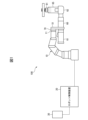
- FIG. 1 is a diagram illustrating a device configuration of a robot system according to an embodiment.
- FIG. 2 is a functional block diagram of the robot system.
- FIG. 4 is a main flow diagram of a screw tightening operation.
- 11A and 11B are diagrams for explaining a screw tightening operation.
- FIG. 13 is a diagram showing a schematic state after the screw has been successfully tightened; 11 is a graph showing an example of changes in tightening torque, tightening depth, and angle over time when the screw tightening is successful.
- FIG. 13 is a diagram showing a schematic diagram of a screw tightening state when the cause of failure is oblique tightening.
- FIG. 13 is a diagram showing a schematic diagram of a screw tightening state when the cause of failure is loosening of the screw.
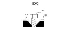
- FIG. 13 is a diagram showing a schematic diagram of a screw tightening state when the cause of failure is a defective pilot hole.
- 13 is a flowchart showing a retry operation executed by a retry unit when the cause of failure is oblique fastening.
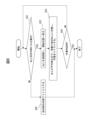
- 13 is a flowchart showing a retry operation executed by a retry unit when the cause of failure is loose screw.
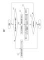
- 13 is a flowchart showing a retry operation executed by a retry unit when the cause of failure is a pilot hole defect.
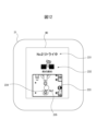
- 13 is a diagram showing an example of an image that the display control unit displays on the display unit when the determination result is successful.
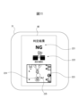
- FIG. 13 is a diagram showing an example of an image that the display control unit displays on the display unit when the determination result is failure and the cause of the failure is oblique fastening.
- FIG. 13A and 13B are diagrams illustrating an example of an image that is displayed on the display unit by the display control unit during execution of a retry.
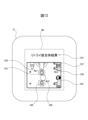
- 13 is a diagram showing an example of an image displayed by the display control unit, showing the work results of the entire screw tightening operation, including retry operations.
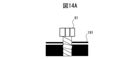
- FIG. FIG. 13 is a diagram showing a schematic diagram of screw breakage as an example of a screw tightening failure.
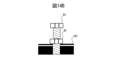
- FIG. 13 is a diagram showing a schematic diagram of a double-threaded state as an example of a screw tightening failure.
- FIG. 13 is a schematic diagram showing an example of a screw tightening failure in which a screw is too short.
- FIG. 1 is a diagram showing the equipment configuration of a robot system 100 according to one embodiment.
- the robot system 100 includes a robot 10, a robot control device 20 that controls the robot 10, and a teaching operation panel 30 connected to the robot control device 20.
- a screw driver 60 serving as an end effector is attached to the flange 11 of the wrist of the robot 10 via a mounting plate 51.
- a force sensor (force detector) 70 that detects external forces is attached between the flange 11 of the wrist and the mounting plate 51.
- the robot system 100 can set the screw driver 60 to a desired position and posture using the robot 10, and perform screw tightening work using the screw driver 60 while having the robot 10 perform force control based on the detection value detected by the force sensor 70.
- the robot 10 is a six-axis vertical articulated robot. Note that various types of robots may be used as the robot 10 depending on the work target, such as a horizontal articulated robot, a parallel link type robot, or a dual-arm robot. In FIG. 1, an example configuration is shown in which the robot 10 is equipped with a screw tightening machine 60 as an end effector, but various types of end effectors can be attached to the robot 10 depending on the work application.
- the robot control device 20 controls the operation of the robot 10 according to an operation program or commands from the teaching operation panel 30.
- the robot control device 20 may have a hardware configuration as a general computer having a processor 21 (see FIG. 2), memory (ROM, RAM, non-volatile memory, etc.), a storage device, an operation unit, an input/output interface, a network interface, etc.
- the teaching operation panel 30 is used as an operation terminal for teaching the robot 10, displaying information, and performing various settings.
- a teaching device configured with a tablet terminal or the like may be used as the teaching operation panel 30.
- the teaching operation panel 30 may have a hardware configuration as a general computer having a processor, memory (ROM, RAM, non-volatile memory, etc.), a storage device, an operation unit, a display unit 31 (see Figure 2), an input/output interface, a network interface, etc.
- the screw fastener 60 is an angle-type screw fastener (nut runner).
- the screw fastener 60 comprises a body portion 61 that contains a control portion 161 and a motor 162 (see FIG. 2), and a head portion 62 that is connected to the tip of the body portion 61.
- the head portion 62 holds a socket 65 as a tool.
- the socket 65 holds a screw 81.
- the screw fastener 60 is connected to the robot control device 20, and rotates the socket 65 in response to a command from the robot control device 20 to tighten and fix the screw 81 into a threaded hole in an object.
- the screw driver 60 is attached to one side of the mounting plate 51, and the other side of the mounting plate 51 is attached to the flange 11 via a force sensor 70.
- the robot 10 can set the screw driver 60 to a desired position and posture to perform screw tightening work on an object.
- the force sensor 70 is, for example, a six-axis force sensor that detects forces acting in the mutually orthogonal X, Y, and Z axis directions, and moments around each axis. Note that in this embodiment, the force sensor 70 is configured to detect an external force acting on the robot 10, but instead of a force sensor, the external force may be detected by the detection value of a torque sensor provided on each axis of the robot.
- FIG. 2 is a functional block diagram of the robot system 100.
- the robot control device 20 includes a motion control unit 121, a force control unit 122, a force data processing unit 123, a determination unit 124, a retry unit 125, a display control unit 126, and a setting unit 127.
- These functional blocks may be functional elements that are realized by the processor 21 of the robot control device 20 executing a program.
- the robot control device 20 includes a memory unit 129.
- the memory unit 129 is, for example, a storage device such as a non-volatile memory or a hard disk device.
- the memory unit 129 stores an operation program for controlling the robot 10, various setting information including force control parameters and operation parameters, and the like.
- the operation control unit 121 controls the operation of the robot 10 according to an operation program or according to commands from the teaching operation panel 30.
- the robot control device 20 is equipped with a servo control unit (not shown) that performs servo control on the motors 111 of each axis according to commands for each axis generated by the operation control unit 121.
- the force data processing unit 123 provides a function for calculating the external force (force and moment) acting on the robot 10 (screw tightening machine 60) based on the detection value of the force sensor 70.
- the position and orientation of the force sensor 70 can be calculated from the position and orientation of the coordinate system of the wrist tip of the robot 10 and the relative position information of the force sensor 70 with respect to the wrist tip.
- the force data processing unit 123 can calculate the magnitude and direction of the force or moment in a preset arbitrary coordinate system based on the position, orientation, and detection value of the force sensor 70.
- the force control unit 122 is responsible for the function of executing force control based on the force information calculated by the force data processing unit 123 and predetermined force control parameters.
- the motion control unit 121 has the function of causing the robot 10 to perform motions using force control under the command of the force control unit 122.
- the determination unit 124 has a function of acquiring time series data for each of a plurality of force control parameters during execution of force control, and judging whether the work performed by the robot 10 is successful or not based on the time series data.
- the determination unit 124 further has a function of analyzing and identifying the cause of failure in screw tightening based on the acquired time series data of the force control parameters.
- the retry unit 125 retries the screw tightening operation depending on the cause of failure identified by the determination unit 124.
- the display control unit 126 provides a function to display various information regarding the results of the screw tightening execution (success/failure, cause of failure, etc.) based on the judgment result by the judgment unit 124.
- the setting unit 127 provides a function for accepting input of various parameters.
- the setting unit 127 may be configured, for example, to display a user interface for accepting input of various parameters on the display unit 31 of the teaching operation panel 30, and to accept operation input via the operation unit.
- step S1 input of various parameters required for the screw tightening operation is accepted (step S1).
- force control parameters and operation parameters of the screw tightening machine 60 (rotation speed, etc.) are input.
- the robot control device 20 (operation control unit 121) controls the robot 10 to position the screw tightening machine 60 at the previously taught screw tightening start position, rotates the screw tightening machine 60 in the forward direction, and starts the screw tightening operation by force control (step S2).
- force control during screw tightening the pressing force, tightening torque, screw tightening depth, angle (angle between the drive shaft of the fastener and the center line of the fastening hole), tightening operation time, etc. are set as parameters and operation control is performed.
- Such parameters related to force control are referred to as force control parameters in this specification.
- the screw tightening operation will be explained with reference to Figure 4.
- arrow A indicates the pressing direction, and the force control unit 122 performs control so that the pressing force in this pressing direction becomes the target force.
- the actual pressing force value is obtained based on the detection value of the force sensor 70.
- the angle ⁇ represents an angle error defined as the angle between the center line C1 of the screw hole 91 and the drive axis C2 of the socket 65 (screw 81).
- the force control unit 122 performs control based on the detection value of the force sensor 70 so that this angle error becomes, for example, zero, that is, so that the moment in the direction of the angle ⁇ detected by the force sensor 70 becomes, for example, zero.
- FIG. 4 also shows a position error d defined as the positional deviation of the center of the tip of the screw 81 relative to the center line C1. Based on the detection value of the force sensor 70, the force control unit 122 can correct the position of the robot 10 so that the position error d of the screw 81 approaches zero.
- the actual measured values of the magnitude and direction of the angle can be obtained based on the position and posture of the robot 10 (screw fastener 60).
- the mounting position of the screw fastener 60 relative to, for example, a flange coordinate system set in the robot 10 is known. Therefore, the position and posture of the screw fastener 60 (i.e., the magnitude and direction of each of the above degrees) can be obtained based on the position and posture of the robot 10.
- the tightening torque is a torque in a direction that rotates the screw 81.
- the tightening torque can be found from the detection value of the force sensor 70 as the force or moment that the robot 10 receives due to the rotation of the screw tightening machine 60 (socket 65).
- the tightening depth can be detected as the amount by which the socket 65 is moved in the pressing direction after the robot 10 positions the screw 81 at the taught position for starting the screw tightening.
- the tightening operation After the start of the screw tightening operation, when the tightening torque reaches the target torque value, the tightening operation can be considered to be completed, the rotation of the screw 81 can be stopped, and the tightening operation can be ended.
- the time from the start of screw tightening to the end of screw tightening in this manner is defined as the fastening operation time.
- the determination unit 124 determines whether the screw tightening was successful or not (step S3).
- the determination unit 124 determines whether the screw tightening was successful or not and the cause of the failure based on the time progression of the detected values of the force control parameters, their mutual correlations, etc. Details of the determination by the determination unit 124 will be described later. If the screw tightening has failed (S3: YES), the determination unit 124 diagnoses the cause of the failure, and the retry unit 125 executes a retry operation according to the cause of the failure (step S4). If the screw tightening was successful (S3: NO), this process ends.
- step S5 the retry unit 125 determines whether all necessary retry operations have been performed. If not all retries have been performed (S5: NO), processing continues from step S3. If it is determined that all retry operations have been performed (S5: YES), the determination unit 124 performs an operation determination regarding the retry operations (step S6). If the operation is successful (S6: YES), this processing ends. If it is determined that the operation has failed (S6: NO), the determination unit 124 determines that the failure occurred due to an unknown cause and records the location of the failure (step S7).
- step S3 determines whether screw tightening is performed by the robot control device 20 or not.
- the determination unit 124 can determine the state of the screw tightening operation by force control based on the following five determination conditions, for example.
- (Decision condition 1) Whether the screw tightening depth reaches the specified screw tightening depth (target value) (Decision condition 2) Whether the tightening torque reaches the specified target torque (Decision condition 3) Whether the pressing force reaches the specified screw tightening pressing force (target force) (Decision condition 4) Whether the angle is within the specified maximum screw tightening angle range (Decision condition 5) Whether the tightening work time is within the specified work time
- Judgment condition 1 is a condition regarding whether or not the screw tightening depth (fastening depth) has reached a target value. Here, as an example, it may be determined that judgment condition 1 is satisfied when the screw tightening depth is within a predetermined range.
- Judgment condition 2 is a condition regarding whether or not the fastening torque has reached the target torque. Here, as an example, it may be determined that judgment condition 2 is satisfied when the detected value of the fastening torque is within a predetermined range.
- Decision condition 3 is a condition regarding whether the pressing force has reached the target force.
- judgment condition 3 is satisfied when the detected value of the pressing force is within a predetermined range.
- Judgment condition 4 is a condition regarding whether the angle during screw tightening (angle ⁇ in FIG. 4) is within a specified maximum angle range. It may be determined that judgment condition 4 is satisfied when the angle during screw tightening is within the maximum angle range (for example, ⁇ a predetermined angle).
- Decision condition 5 is a condition related to the fastening operation time from the start of screw tightening to the end of screw tightening. Regarding the operation time, it may be determined that judgment condition 5 is satisfied if the fastening operation time is within a target value, or it may be determined that judgment condition 5 is satisfied if the fastening operation time is within the range between the target minimum time and the target maximum time.
- the judgment unit 124 judges that the screw tightening operation is successful when all of the judgment conditions 1 to 5 are satisfied.
- the judgment unit 124 may judge that the screw tightening operation is unsuccessful when one or more of the judgment conditions 1 to 5 are not satisfied.
- the judgment unit 124 may judge the operation result for the judgment conditions 1 to 5 by taking into account the time progression of the parameters related to those conditions.
- the judgment unit 124 may judge the operation result of the screw tightening operation based on the time progression of the parameters related to the judgment conditions 1 to 5 and their mutual relationships.
- the judgment unit 124 may judge the operation result based on the four judgment conditions of judgment conditions 1-2 and 4-5, excluding judgment condition 3 related to the pressing force. That is, the judgment unit 124 may judge that the screw tightening operation is successful when all of judgment conditions 1-2 and 4-5 are satisfied. Furthermore, the judgment unit 124 may judge that the screw tightening operation is unsuccessful when one or more of the judgment conditions 1-2 and 4-5 are not satisfied. The judgment unit 124 may judge the operation result for the judgment conditions 1-2 and 4-5 by taking into account the time transition of the parameters related to them. The judgment unit 124 may judge the operation result of the screw tightening operation based on the time transition of the parameters related to the judgment conditions 1-2 and 4-5 and the relationship between them.
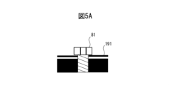
- FIG. 5A is a diagram showing a schematic diagram of a state after the screw tightening is successful.
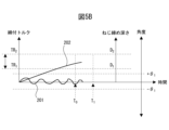
- FIG. 5B is a graph showing an example of the time transition of the tightening torque, the screw tightening depth, and the angle when the screw tightening is successful.
- the vertical axis shows the tightening torque, the screw tightening depth, or the angle
- the horizontal axis shows the time axis.
- T0 and T1 are respectively the minimum work time and the maximum work time as the target value of the fastening work time specified as the judgment condition 5.
- FIG. 5B shows an example of a method of specifying the target value of the fastening work time, in which the judgment condition 5 is OK when the fastening work time is within the time range specified by the minimum work time T0 and the maximum work time T1 .
- a graph 201 shows the change in angle over time.
- the angle changes within a preset maximum angle range ( ⁇ 1 degree) from the start to the end of screw tightening.
- the judgment unit 124 judges that judgment condition 4 regarding the angle is OK.
- a graph 202 shows the time progression of the tightening torque and the screw tightening depth.
- the tightening torque and the screw tightening depth usually show a gradual increase from the start of the screw tightening, so the graph 202 shows the time progression of the tightening torque and the screw tightening depth.
- the tightening torque usually increases gradually from the start of the screw tightening as shown in the graph 202, and reaches the target force within the target work time or within the range of the target work time ( T0 to T1 ).
- the determination unit 124 may determine that the determination condition 2 is OK when the tightening torque reaches the target torque (range TR1 to TR2 ).
- the determination unit 124 may determine that the determination condition 2 is OK when the tightening torque reaches the target torque within the target work time.
- the screw tightening depth normally increases gradually from the start of screw tightening as shown in graph 202, and reaches the target value within the target work time or within the range of the target work time ( T0 to T1 ).
- the judgment unit 124 may judge that judgment condition 1 is OK when the screw tightening depth reaches the target value (range D1 to D2 ).
- the judgment unit 124 may judge that judgment condition 1 is OK when the screw tightening depth reaches the target value within the target work time.
- the determination unit 124 may determine that the determination condition 5 is satisfied.
- the determination unit 124 may also determine that the determination condition 2 is OK for the pressing force when the pressing force reaches the target force. Alternatively, the determination unit 124 may determine that the determination condition 2 is OK for the pressing force when the pressing force reaches the target force within the target work time.
- the determination unit 124 The screw tightening depth has not reached the target value (range D1 to D2 ) (judgment condition 1 is NG).
- the tightening torque has not reached the target force (range TR1 to TR2 ) (judgment condition 2 is NG).
- the pressing force does not reach the target force (target range) (judgment condition 3 is NG).
- the screw tightening angle is not within the specified range ( ⁇ 1 degree) (judgment condition 4 is NG). Screw tightening is not completed within the specified work target time ( T0 to T1 ) (judgment condition 5 is NG), If any one of the above conditions is satisfied, it may be determined that the screw tightening has failed.
- the judgment unit 124 can identify the cause of failure in screw tightening based on the judgment results of the judgment conditions 1 to 5 after taking into account the changes over time of the parameters for these judgment conditions and their correlations. Alternatively, the judgment unit 124 may identify the cause of failure in screw tightening based on the judgment results of the judgment conditions 1-2 and 4-5 after taking into account the changes over time of the parameters for these judgment conditions and their correlations.
- the determination unit 124 may identify the cause of failure when screw tightening fails based on at least determination condition 1, determination condition 2, and determination condition 4.
- determination condition 1 determination condition 1
- determination condition 2 determination condition 4
- Figures 6A to 6C an example in which the determination unit 124 identifies the cause of failure based on determination condition 1, determination condition 2, and determination condition 4 will be described.
- FIG. 6A is a schematic diagram showing a screw tightening state when the cause of failure is oblique tightening.
- the screw 81 in the oblique tightening state, the screw 81 is fitted and fixed in an inclined state with respect to the screw hole of the target object 191. Therefore, in this case, the tightening torque reaches the target torque at an early stage of the screw tightening, and the screw tightening ends at an early stage.
- the early stage refers to a stage before the specified target work time range is reached. The angle becomes larger than the maximum angle. Also, the screw tightening depth does not reach the target value.
- the judgment unit 124 judges the following judgment results (a1) to (a3) for (judgment condition 1), (judgment condition 2), and (judgment condition 4), and when the judgment results (a1) to (a3) are established, it can be determined that the cause of the screw tightening failure is oblique tightening.
- judgment condition 1 Since the tightening depth does not reach the target value, judgment condition 1 is NG.
- judgment condition 2 Since the fastening torque reaches the target torque, judgment condition 2 is OK.
- the angle exceeds the maximum angle range, so judgment condition 4 is not met.
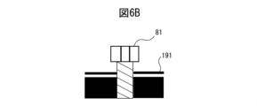
- FIG. 6B is a schematic diagram showing a screw tightening state when the cause of failure is screw loosening (fastener loosening).
- Screw loosening can occur, for example, when the length of the under-head of the screw 81 is longer than a specified value (when the screw is defective).
- the distance from the tip of the screw to the screw hole when the robot 10 (screw tightening machine 60) is positioned at the teaching position for starting screw tightening becomes shorter than when the screw length is normal, and the screw tightening depth measured as the movement amount of the robot 10 (screw tightening machine 60) from the screw tightening start position becomes smaller than the target value.
- the judgment unit 124 judges the following judgment results (b1) to (b3) for (judgment condition 1), (judgment condition 2), and (judgment condition 4), and when the judgment results (b1) to (b3) are established, it can be determined that the cause of the screw tightening failure is screw loosening.
- judgment condition 1 Since the tightening depth does not reach the target value, judgment condition 1 is NG.
- judgment condition 2 Since the fastening torque reaches the target torque, judgment condition 2 is OK.
- judgment condition 4 Since the angle is within the maximum angle range, judgment condition 4 is OK.
- Fig. 6C is a schematic diagram showing a screw tightening state when the cause of failure is a pilot hole defect.
- a pilot hole defect is a state in which the upper part of the screw hole 191a of the target object 191 is deformed so as to be greatly widened. Therefore, the determination unit 124 determines the following determination results (c1) to (c3) for (Determination Condition 1), (Determination Condition 2), and (Determination Condition 4), and when the determination results (c1) to (c3) are established, it can be determined that the cause of the screw tightening failure is screw loosening.
- the tightening depth gradually increases and reaches the target value, so judgment condition 1 is OK.
- the judgment unit 124 when judging whether the tightening depth (judgment condition 1), tightening torque (judgment condition 2), and angle (judgment condition 4) are OK/NG, the judgment unit 124 also takes into account the time progression of the force control parameters related to these judgment conditions to identify the cause of failure.
- the retry unit 125 performs an appropriate retry operation depending on the diagnosis of the cause of failure by the determination unit 124 as described above.
- FIG. 7 is a flowchart showing the retry operation executed by the retry unit 125 when the cause of failure is oblique fastening.
- This retry operation (and each retry operation described below) is executed under the control of the processor 21 of the robot control device 20.
- the retry operation shown in FIG. 7 corresponds to the retry process by the processing loop consisting of steps S3 (S3: YES), S4, and S5 of the main flow (FIG. 3).
- step S11 the cause of failure determined by the determination unit 124 is confirmed (step S11). If it is determined that the cause of failure is oblique tightening (S11: YES), the operation from step S12 is performed. In step S12, the retry unit 125 rotates the screw in the reverse direction, returning the screw to the starting position of the screw tightening. Next, the retry unit 125 corrects the position and posture of the screw in the opposite direction to the angle (tilt direction) that was detected to be excessive during screw tightening, and performs screw tightening again (step S13). Here, the position and posture of the screw are corrected to the opposite direction to the tilt direction in which the detected angle is maximum or the detected angle is relatively large.
- the retry unit 125 judges whether or not the screw tightening was successful (step S14). If the screw tightening has failed (S14: NO), the retry unit 125 executes the process from step S11 again. In a situation where the screw is being tightened at an angle, the retry unit 125 gradually adjusts the position and posture of the screw in the direction opposite to the detected angle (tilt direction) and tightens the screw (loop from steps S11 to S14: NO). If the screw tightening is successful (S14: YES), this process ends. Note that if the cause of failure is something other than the screw tightening at an angle (S11: NO), the screw tightening is retried using another measure (step S15). The above process makes it possible to eliminate the screw tightening at an angle and to tighten the screw properly.
- FIG. 8 is a flowchart showing the retry operation performed by the retry unit 125 when the cause of failure is loose screw.
- the cause of failure determined by the determination unit 124 is confirmed (step S21). If it is determined that the cause of failure is loose screw (S21: YES), the operation from step S22 is performed.
- the retry unit 125 reverses the rotation of the screw and returns it to the starting position for screw tightening. Loose screw occurs when the screw is a rejected product. Therefore, the retry unit 125 automatically replaces the screw with another screw and tightens the screw again (step S23).
- step S24 judges whether or not the screw tightening was successful (step S24). If the screw tightening has failed (S24: NO), the process is executed again from step S21. If the screw tightening has been successful (S24: YES), this process ends. Note that if the cause of failure is something other than loose screw (S21: NO), a retry of the screw tightening is performed using another measure (step S25). Through the above process, the loose screw condition is resolved and the screw can be tightened properly.
- FIG. 9 is a flowchart showing the retry operation executed by the retry unit 125 when the cause of failure is a defective pilot hole.
- the cause of failure determined by the determination unit 124 is confirmed (step S31). If it is determined that the cause of failure is a defective pilot hole (S31: YES), the operation from step S32 is performed.
- the retry unit 125 reverses rotation of the screw and returns the screw to the starting position for screw tightening.
- the retry unit 125 then issues an alarm indicating a defective pilot hole, marks the location of the defective pilot hole on a visualized image of the work object, and moves to the next work location (step S33).
- step S34 judges whether or not the screw tightening was successful (step S34). If the screw tightening has failed (S34: NO), the process is executed again from step S31. If the screw tightening has been successful (S34: YES), this process ends. If the cause of failure is something other than a poor pilot hole, the screw tightening is retried using other measures (step S35). As a result of the above process, if the pilot hole is poor, an alarm is output, and information regarding the cause of failure is recorded and displayed, etc.
- the retry unit 125 can perform appropriate retry operations depending on the cause of failure diagnosed by the determination unit 124.
- the following describes the display function of the display control unit 126 for displaying information related to the judgment result by the judgment unit 124.
- the display control unit 126 displays information related to the judgment result by the judgment unit 124 on the display unit 31 of the teaching operation panel 30.
- Image M1 shows an example of image M1 that the display control unit 126 displays on the display unit 31 when the judgment result is successful.
- Image M1 may be displayed in real time, for example, when the judgment is made in step S3 in the main flow.
- image M1 includes a message image 211 including a message indicating that the judgment result is successful, and a visualization image 212 that visualizes the work object.
- a frame line 213 indicating the work location on the object and text information 214 indicating the work number are superimposed on the visualization image 212.
- the user can instantly grasp the work result (OK/NG), the work location on the work object, and the work number.
- the text information "OK" the frame line, and the work number may be displayed in, for example, green or blue so that it can be instantly understood that the work result is OK.
- image M2 shows an example of image M2 that the display control unit 126 displays on the display unit 31 when the judgment result is failure and the cause of failure is diagonal tightening.
- Image M2 may be displayed in real time, for example, when the judgment is made in step S3 in the main flow.
- image M2 includes a message image 221 indicating that the judgment result is failure, and a message image 222 indicating the cause of failure.
- Image M2 further includes a visualized image 223 that visualizes the work object. In the visualized image 223, a frame line 224 indicating the part on the work object that was diagonally tightened and text information 225 indicating the work number are superimposed.
- image M3 shows an example of an image M3 that the display control unit 126 displays on the display unit 31 during a retry.
- Image M4 may be displayed in real time while the retry operation in step S4 of the main flow is being performed.
- image M3 includes a message image 231 indicating that a retry is in progress, and a message image 232 indicating that the cause of the retry (cause of failure) is diagonal tightening.
- Image M3 further includes a visualization image 233 that visualizes the work object, and visualization image 233 includes a frame 234 indicating the work location of the retry and text information 235 indicating the work number.
- the user can instantly grasp that a retry operation is being performed, the cause of the failure that is being resolved by the retry, and the target location and work number of the retry.
- the frame 234 and the text information 235 indicating the work number may be displayed in red, for example, to indicate that recovery by retry is being performed.
- Figure 13 is an example of image M4 displayed by display control unit 126, showing the work result of the entire screw tightening operation including the retry operation.
- Image M4 may be displayed in real time, for example, when processing step S6 in the main flow is performed.
- image M4 includes message image 241 indicating that image M4 is the result of the entire operation including retries, and visualized image diagram 242 which visualizes the work object.
- Visualized image 242 has frame lines 243, 245, 247 indicating the work locations and text information 244, 246, 248 indicating the respective work numbers superimposed thereon.
- Image M4 may be displayed so that it is possible to distinguish whether each work location has been successful or unsuccessful by color. For example, if task number No. 1 and No. 2 are successful and task number No.
- the display control unit 126 may display the frame line 243, text information 244, frame line 245, and text information 246 in blue (or green), and the frame line 247 and text information 248 in red. In this case, the user can instantly grasp the location of the work on the work object and the results of the work.
- failure causes identified by the determination unit 124 oblique tightening, loose screws, and poor pilot holes.
- the determination unit 124 can identify various other failure causes in addition to these.
- the determination unit 124 can identify the cause of failure as follows, based on the determination results for (Determination Condition 1), (Determination Condition 2), and (Determination Condition 4) and the time transition of the force control parameter related to these determination conditions.
- the determination unit 124 makes a determination as shown in the following determination results (d1) to (d3) for (Determination Condition 1), (Determination Condition 2), and (Determination Condition 4), and can identify that the cause of the screw tightening failure is screw breakage when the determination results (d1) to (d3) are satisfied.
- (d1) The tightening depth gradually increases and reaches the target value, so judgment condition 1 is OK.
- (d2) The tightening torque increases as soon as screw tightening begins, but does not reach the target force and instead decreases midway. Therefore, judgment condition 2 is NG.
- judgment condition 4 Since the angle is within the maximum angle range, judgment condition 4 is OK.
- the judgment unit 124 can identify the cause of failure as follows, based on the judgment results for (judgment condition 1), (judgment condition 2), and (judgment condition 4) and the time transition of the force control parameter related to these judgment conditions. Specifically, the judgment unit 124 judges the following judgment results (e1) to (e3) for (judgment condition 1), (judgment condition 2), and (judgment condition 4), and can identify that the cause of the screw tightening failure is double-threading when the judgment results (e1) to (e3) are satisfied.
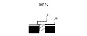
- FIG. 14C shows a schematic diagram of a case where the length of the fastener is shorter than a specified value (assuming here that the screw is too short as a specific example) as an example of a screw tightening failure.
- the judgment unit 124 can identify the cause of failure as follows based on the judgment results for (judgment condition 1), (judgment condition 2), (judgment condition 3), and (judgment condition 4) and the time transition of the force control parameters related to these judgment conditions.
- the judgment unit 124 judges the following judgment results (f1) to (f4) for (judgment condition 1), (judgment condition 2), (judgment condition 3), and (judgment condition 4), and can identify that the cause of the screw tightening failure is a double screw when the judgment results (f1) to (f4) are satisfied.
- the judgment result (f4) is added and it is determined that the screw is too short when the tightening operation time is shorter than a specific value.
- judgment condition 1 Since the tightening depth does not reach the target value, judgment condition 1 is NG.
- judgment condition 2 Since the tightening torque reaches the target value, judgment condition 2 is OK.
- judgment condition 4 Since the angle is within the maximum angle range, judgment condition 4 is OK.
- the fastening operation time is shorter than the specific value and does not reach the target range, so that judgment condition 5 is NG.
- the retry action can be the same as the retry action when the cause of failure is loose screw ( Figure 8).
- the worker can grasp the work results in real time while performing the work.
- the cause of failure in work due to force control can be accurately identified based on the time progression of multiple force control parameters during force control operation and their mutual correlation. Furthermore, the cause of this failure can also be provided to the worker in real time while the work is being performed.
- screw tightening has been described as an example of a work using force control, but the work to which this embodiment can be applied can include various work using force control.
- the configuration of the above embodiment can be applied to a fitting work.
- a fitting work for example, a cylindrical fitting work is fitted into a hole formed in a fitted work.
- the pressing force, fitting depth, and posture of the fitting work can be used as force control parameters. Based on the actual measured values of these parameters relative to the target values, their time progression, and the relationship between them, the success/failure of the fitting work and the cause of failure can be identified.
- the functional blocks in the functional block diagram shown in Figure 2 may be realized by the processor of the robot control device executing various software stored in a storage device, or may be realized by a hardware-based configuration such as an ASIC (Application Specific Integrated Circuit).
- ASIC Application Specific Integrated Circuit
- the programs that execute the various processes such as the screw tightening operation and retry operation in the above-mentioned embodiment can be recorded on various computer-readable recording media (for example, semiconductor memory such as ROM, EEPROM, flash memory, magnetic recording media, and optical disks such as CD-ROM and DVD-ROM).
- semiconductor memory such as ROM, EEPROM, flash memory, magnetic recording media, and optical disks such as CD-ROM and DVD-ROM.
- the determination unit (124) determines the following determination conditions (1) to (4): (1) The fastening depth reaches a specified depth; (2) The tightening torque reaches a specified target torque. (3) the angle is within a specified maximum angle range; and (4) A control device (20) as described in appendix 4, which determines that the fastening operation is successful when the fastening operation time is within a specified operation time.
- Appendix 6 The control device (20) described in Appendix 5, wherein the judgment unit (124) judges that the fastening operation has failed when at least one of the judgment conditions (1) to (4) is not satisfied.
- (Appendix 7) The control device (20) described in Appendix 5 or 6, wherein the judgment unit (124) identifies a cause of failure when the specified task fails based on at least the judgment conditions (1) to (3) and time-series data of force control parameters related to the judgment conditions (1) to (3).
- (Appendix 8) The control device (20) described in Appendix 7, wherein the causes of failure identified by the judgment unit (124) based on at least the judgment conditions (1) to (3) and the time-series data of the force control parameters related to the judgment conditions (1) to (3) include at least one of oblique tightening, fastener loosening, poor pilot hole, fastener breakage, and double threading.
- the control device (20) described in Appendix 9 includes, when the cause of the failure is the oblique tightening, rotating the fastener in the reverse direction, returning it to the fastening start position, adjusting the posture of the fastener in the opposite direction to the detected inclination direction of the fastener, and performing the fastening operation again.
- a robot system comprising: a robot (10); a force detector (70) that detects forces and moments acting on the robot; a force control unit (122) that causes the robot (10) to perform a predetermined task by force control based on the detection value of the force detector (70) and a plurality of predetermined force control parameters; and a judgment unit (124) that acquires time series data of the plurality of predetermined force control parameters while the force control is being executed, and judges whether the predetermined task is successful or not based on the time series data.
Landscapes
- Engineering & Computer Science (AREA)
- Mechanical Engineering (AREA)
- Robotics (AREA)
- Human Computer Interaction (AREA)
- Details Of Spanners, Wrenches, And Screw Drivers And Accessories (AREA)
- Manipulator (AREA)
Abstract
Description
(判定条件1)ねじ締め深さが指定したねじ締めの深さ(目標値)に達しているか
(判定条件2)締結トルクが指定した目標トルクに達しているか
(判定条件3)押付力が指定したねじ締め押付力(目標力)に達しているか
(判定条件4)角度が指定したねじ締めの最大角度の範囲内に収まっているか
(判定条件5)締結作業時間が指定した作業時間内となっているか
・ねじ締め深さが目標値(範囲D1からD2)に到達していない(判定条件1がNGである)、
・締付トルクが目標力(範囲TR1からTR2)に到達していない(判定条件2がNGである)、
・押付力が目標力(目標範囲)に到達していない(判定条件3がNGである)、
・ねじ締めの角度が所定の範囲(±θ1度)に入っていない(判定条件4がNGである)、
・ねじ締めが指定した作業目標時間(T0からT1)内で終了していない(判定条件5がNGである)、
のいずれかの条件が満たされる場合に、ねじ締めが失敗であると判定しても良い。
(a1)締付け深さは目標値に到達しないため、判定条件1はNGである。
(a2)締付トルクは目標トルクに到達するため、判定条件2はOKである。
(a3)角度は最大角度範囲を超えて大きくなるため、判定条件4はNGである。
(b1)締付け深さは目標値に到達しないため、判定条件1はNGである。
(b2)締付トルクは目標トルクに到達するため、判定条件2はOKである。
(b3)角度は最大角度範囲の範囲であるため、判定条件4はOKである。
(c1)締付け深さは次第に増加し目標値に到達するので、判定条件1はOKである。
(c2)締付トルクはねじ締めがある程度進行するまでは実質的にゼロで、その後目標トルクまで上昇する変化を示す。よって、この場合、判定条件2はNGであると判定する。
(c3)角度は最大角度範囲の範囲であるため、判定条件4はOKである。

(d1)締付け深さは次第に増加し目標値に到達するので、判定条件1はOKである。
(d2)締付トルクはねじ締めの開始と共に上昇するが、目標力に到達せず途中で低下する変化を示すため、判定条件2はNGである。
(d3)角度は最大角度範囲の範囲であるため、判定条件4はOKである。
(e1)締付け深さは増加を示さず目標値に到達しないため、判定条件1はNGである。
(e2)締付トルクは正常な増加を示さず低い値に留まるため、判定条件2はNGである。
(e3)角度は最大角度範囲の範囲であるため、判定条件4はOKである。
(f1)締付け深さは目標値に到達しないため、判定条件1はNGである。
(f2)締付トルクは目標値に到達するため、判定条件2はOKである。
(f3)角度は最大角度範囲の範囲であるため、判定条件4はOKである。
(f4)締結作業時間が特定の値よりも短く目標範囲内に到達していないので、判定条件5はNGである。
(付記1)
ロボット(10)を制御する制御装置(20)であって、前記ロボット(10)に作用する力及びモーメントを検出する力検出器(70)の検出値及び所定の複数の力制御パラメータに基づいて前記ロボット(10)に力制御による所定の作業を実行させる力制御部(122)と、前記力制御の実行中における前記所定の複数の力制御パラメータの時系列データを取得し、前記時系列データに基づき前記所定の作業が成功であるか否かを判定する判定部(124)と、を備える制御装置(20)。
(付記2)
前記判定部(124)は、前記時系列データの関連性に基づき、前記所定の作業が成功であるか否かを判定する、付記1に記載の制御装置(20)。
(付記3)
前記判定部(124)は、前記時系列データの関連性に基づき、前記所定の作業が失敗である場合の原因を特定する、付記1又は2に記載の制御装置(20)。
(付記4)
前記所定の作業は、締結作業であり、前記所定の複数の力制御パラメータは、締結深さ、締付トルク、締結具の駆動軸と締結穴の中心線との間の角度、及び締結作業時間を含む、付記1から3のいずれか一項に記載の制御装置(20)。
(付記5)
前記判定部(124)は、以下の判定条件(1)から(4):
(1)前記締結深さが、指定した深さに達していること、
(2)前記締付トルクが、指定した目標トルクに達していること、
(3)前記角度が、指定した最大角度の範囲内に収まっていること、及び、
(4)前記締結作業時間が、指定した作業時間内となっていること
が満たされている場合に、前記締結作業が成功であると判定する、付記4に記載の制御装置(20)。
(付記6)
前記判定部(124)は、前記判定条件(1)から(4)の少なくとも一つが満たされていない場合に前記締結作業に失敗したと判定する、付記5に記載の制御装置(20)。
(付記7)
前記判定部(124)は、少なくとも前記判定条件(1)から(3)、及び当該判定条件(1)から(3)に係わる力制御パラメータの時系列データに基づいて前記所定の作業が失敗である場合の失敗原因を特定する、付記5又は6に記載の制御装置(20)。
(付記8)
前記判定部(124)が少なくとも前記判定条件(1)から(3)、及び当該判定条件(1)から(3)に係わる力制御パラメータの時系列データに基づいて特定する前記失敗原因は、斜め締め、締結具浮き、下穴不良、締結具破損、二度ねじ、の少なくとも一つを含む、付記7に記載の制御装置(20)。
(付記9)
前記失敗の原因に応じて、前記力制御による動作をリトライする再試行部(125)を更に備える、付記8に記載の制御装置(20)。
(付記10)
前記リトライは、前記失敗の原因が前記斜め締めである場合に、前記締結具を逆回転し、締結開始位置へ戻した上で、検出された前記締結具の傾斜方向の逆方向へ前記締結具の姿勢を調整し前記締結作業を再度実行すること、を含む、付記9に記載の制御装置(20)。
(付記11)
前記リトライは、前記失敗の原因が前記締結具浮きである場合に、前記締結具を逆回転し、締結開始位置へ戻した上で、前記締結具を他の締結具に交換し前記締結作業を再度実行すること、を含む、付記9に記載の制御装置(20)。
(付記12)
前記リトライは、前記失敗の原因が前記下穴不良である場合に、前記締結具を逆回転し、締結開始位置へ戻した上で、下穴不良であることの表示又は記録を行い、次の作業箇所に移動すること、を含む、付記9に記載の制御装置(20)。
(付記13)
前記判定部(124)による判定結果に関する情報を表示画面に表示する表示制御部(126)を更に備える、付記1から12のいずれか一項に記載の制御装置。
(付記14)
前記表示画面に表示される前記判定結果に関する情報は、前記所定の作業の成功又は失敗を示す画像、失敗原因を示す画像、又は、作業対象物の画像上に作業箇所、作業番号及び作業の成功又は失敗を示す画像を重畳した画像、の少なくともいずれかを含む、付記13に記載の制御装置(20)。
(付記15)
ロボット(10)と、前記ロボットに作用する力及びモーメントを検出する力検出器(70)と、前記力検出器(70)の検出値及び所定の複数の力制御パラメータに基づいて前記ロボット(10)に力制御による所定の作業を実行させる力制御部(122)と、前記力制御の実行中における前記所定の複数の力制御パラメータの時系列データを取得し、前記時系列データに基づき前記所定の作業が成功であるか否かを判定する判定部(124)と、を備えるロボットシステム(100)。
11 フランジ
20 ロボット制御装置
21 プロセッサ
30 教示操作盤
31 表示部
60 ねじ締め機
61 ボディ部
62 ヘッド部
65 ソケット
70 力センサ
81 ねじ
100 ロボットシステム
111 モータ
121 動作制御部
122 力制御部
123 力データ処理部
124 判定部
125 再試行部
126 表示制御部
127 設定部
129 記憶部
161 制御部
162 モータ
212、223、233、242 可視化画像
Claims (15)
- ロボットを制御する制御装置であって、
前記ロボットに作用する力及びモーメントを検出する力検出器の検出値及び所定の複数の力制御パラメータに基づいて前記ロボットに力制御による所定の作業を実行させる力制御部と、
前記力制御の実行中における前記所定の複数の力制御パラメータの時系列データを取得し、前記時系列データに基づき前記所定の作業が成功であるか否かを判定する判定部と、
を備える制御装置。 - 前記判定部は、前記時系列データの関連性に基づき、前記所定の作業が成功であるか否かを判定する、請求項1に記載の制御装置。
- 前記判定部は、前記時系列データの関連性に基づき、前記所定の作業が失敗である場合の原因を特定する、請求項1又は2に記載の制御装置。
- 前記所定の作業は、締結作業であり、
前記所定の複数の力制御パラメータは、締結深さ、締付トルク、締結具の駆動軸と締結穴の中心線との間の角度、及び締結作業時間を含む、請求項1から3のいずれか一項に記載の制御装置。 - 前記判定部は、以下の判定条件(1)から(4):
(1)前記締結深さが、指定した深さに達していること、
(2)前記締付トルクが、指定した目標トルクに達していること、
(3)前記角度が、指定した最大角度の範囲内に収まっていること、及び、
(4)前記締結作業時間が、指定した作業時間内となっていること
が満たされている場合に、前記締結作業が成功であると判定する、請求項4に記載の制御装置。 - 前記判定部は、前記判定条件(1)から(4)の少なくとも一つが満たされていない場合に前記締結作業に失敗したと判定する、請求項5に記載の制御装置。
- 前記判定部は、少なくとも前記判定条件(1)から(3)、及び当該判定条件(1)から(3)に係わる力制御パラメータの時系列データに基づいて前記所定の作業が失敗である場合の失敗原因を特定する、請求項5又は6に記載の制御装置。
- 前記判定部が少なくとも前記判定条件(1)から(3)、及び当該判定条件(1)から(3)に係わる力制御パラメータの時系列データに基づいて特定する前記失敗原因は、斜め締め、締結具浮き、下穴不良、締結具破損、二度ねじ、の少なくとも一つを含む、請求項7に記載の制御装置。
- 前記失敗の原因に応じて、前記力制御による動作をリトライする再試行部を更に備える、請求項8に記載の制御装置。
- 前記リトライは、前記失敗の原因が前記斜め締めである場合に、
前記締結具を逆回転し、締結開始位置へ戻した上で、
検出された前記締結具の傾斜方向の逆方向へ前記締結具の姿勢を調整し前記締結作業を再度実行すること、を含む、請求項9に記載の制御装置。 - 前記リトライは、前記失敗の原因が前記締結具浮きである場合に、
前記締結具を逆回転し、締結開始位置へ戻した上で、
前記締結具を他の締結具に交換し前記締結作業を再度実行すること、を含む、請求項9に記載の制御装置。 - 前記リトライは、前記失敗の原因が前記下穴不良である場合に、
前記締結具を逆回転し、締結開始位置へ戻した上で、
下穴不良であることの表示又は記録を行い、次の作業箇所に移動すること、を含む、請求項9に記載の制御装置。 - 前記判定部による判定結果に関する情報を表示画面に表示する表示制御部を更に備える、請求項1から12のいずれか一項に記載の制御装置。
- 前記表示画面に表示される前記判定結果に関する情報は、前記所定の作業の成功又は失敗を示す画像、失敗原因を示す画像、又は、作業対象物の画像上に作業箇所、作業番号及び作業の成功又は失敗を示す画像を重畳した画像、の少なくともいずれかを含む、請求項13に記載の制御装置。
- ロボットと、
前記ロボットに作用する力及びモーメントを検出する力検出器と、
前記力検出器の検出値及び所定の複数の力制御パラメータに基づいて前記ロボットに力制御による所定の作業を実行させる力制御部と、
前記力制御の実行中における前記所定の複数の力制御パラメータの時系列データを取得し、前記時系列データに基づき前記所定の作業が成功であるか否かを判定する判定部と、
を備えるロボットシステム。
Priority Applications (5)
| Application Number | Priority Date | Filing Date | Title |
|---|---|---|---|
| PCT/JP2023/012961 WO2024201842A1 (ja) | 2023-03-29 | 2023-03-29 | 制御装置及びロボットシステム |
| JP2025509454A JPWO2024201842A1 (ja) | 2023-03-29 | 2023-03-29 | |
| DE112023005659.5T DE112023005659T5 (de) | 2023-03-29 | 2023-03-29 | Steuervorrichtung und Robotersystem |
| CN202380096105.9A CN120858011A (zh) | 2023-03-29 | 2023-03-29 | 控制装置以及机器人系统 |
| TW113107170A TW202438262A (zh) | 2023-03-29 | 2024-02-29 | 控制裝置及機器人系統 |
Applications Claiming Priority (1)
| Application Number | Priority Date | Filing Date | Title |
|---|---|---|---|
| PCT/JP2023/012961 WO2024201842A1 (ja) | 2023-03-29 | 2023-03-29 | 制御装置及びロボットシステム |
Publications (1)
| Publication Number | Publication Date |
|---|---|
| WO2024201842A1 true WO2024201842A1 (ja) | 2024-10-03 |
Family
ID=92903696
Family Applications (1)
| Application Number | Title | Priority Date | Filing Date |
|---|---|---|---|
| PCT/JP2023/012961 Ceased WO2024201842A1 (ja) | 2023-03-29 | 2023-03-29 | 制御装置及びロボットシステム |
Country Status (5)
| Country | Link |
|---|---|
| JP (1) | JPWO2024201842A1 (ja) |
| CN (1) | CN120858011A (ja) |
| DE (1) | DE112023005659T5 (ja) |
| TW (1) | TW202438262A (ja) |
| WO (1) | WO2024201842A1 (ja) |
Citations (3)
| Publication number | Priority date | Publication date | Assignee | Title |
|---|---|---|---|---|
| JPH06155192A (ja) * | 1992-11-26 | 1994-06-03 | Sanyo Mach Works Ltd | ねじ締め付け機のトルクカーブ表示装置 |
| JP2002263968A (ja) * | 2001-03-09 | 2002-09-17 | Toshiba Tungaloy Co Ltd | ボルト締結機の制御装置 |
| JP2017127908A (ja) * | 2016-01-18 | 2017-07-27 | ファナック株式会社 | ロボットが出力する回転力を用いるねじ締め装置 |
-
2023
- 2023-03-29 CN CN202380096105.9A patent/CN120858011A/zh active Pending
- 2023-03-29 WO PCT/JP2023/012961 patent/WO2024201842A1/ja not_active Ceased
- 2023-03-29 JP JP2025509454A patent/JPWO2024201842A1/ja active Pending
- 2023-03-29 DE DE112023005659.5T patent/DE112023005659T5/de active Pending
-
2024
- 2024-02-29 TW TW113107170A patent/TW202438262A/zh unknown
Patent Citations (3)
| Publication number | Priority date | Publication date | Assignee | Title |
|---|---|---|---|---|
| JPH06155192A (ja) * | 1992-11-26 | 1994-06-03 | Sanyo Mach Works Ltd | ねじ締め付け機のトルクカーブ表示装置 |
| JP2002263968A (ja) * | 2001-03-09 | 2002-09-17 | Toshiba Tungaloy Co Ltd | ボルト締結機の制御装置 |
| JP2017127908A (ja) * | 2016-01-18 | 2017-07-27 | ファナック株式会社 | ロボットが出力する回転力を用いるねじ締め装置 |
Non-Patent Citations (1)
| Title |
|---|
| MATSUNO TAKAYUKI, SHIRATSUCHI KOJI, HUANG JIAN, FUKUDA TOSHIO: "Fault Detection Algorithm for Thread Fastening by Robotic Manipulator", JOURNAL OF THE ROBOTICS SOCIETY OF JAPAN, vol. 30, no. 8, 1 January 2012 (2012-01-01), pages 804 - 812, XP093213895, DOI: 10.7210/JRSJ.30.804 * |
Also Published As
| Publication number | Publication date |
|---|---|
| DE112023005659T5 (de) | 2025-11-27 |
| TW202438262A (zh) | 2024-10-01 |
| CN120858011A (zh) | 2025-10-28 |
| JPWO2024201842A1 (ja) | 2024-10-03 |
Similar Documents
| Publication | Publication Date | Title |
|---|---|---|
| US11167417B2 (en) | Robot control device and robot system | |
| US9586317B2 (en) | Controlling method of robot system, program, recording medium, and robot system | |
| US11389954B2 (en) | Robot control device | |
| US10500724B2 (en) | Robot teaching device for correcting robot trajectory | |
| US20190232492A1 (en) | Robot control device and robot system | |
| JP5496129B2 (ja) | ロボットのねじ締め作業異常検知方法 | |
| JP6677694B2 (ja) | ロボットシステム | |
| JP7015267B2 (ja) | ロボット制御装置及びロボットシステム | |
| JP7414507B2 (ja) | 制御装置、計測システム、計測方法 | |
| JP7358049B2 (ja) | 制御方法、プログラム、記録媒体、ロボットシステム、および物品の製造方法 | |
| JP2016221582A (ja) | 異常検出方法、および生産制御方法 | |
| WO2024201842A1 (ja) | 制御装置及びロボットシステム | |
| JP2023125498A (ja) | ねじ締めシステム、コントローラ、および制御プログラム | |
| CN117545595A (zh) | 使用拧紧系统对螺栓的拧紧过程进行计算机实施的监督的方法和装置 | |
| US20250100154A1 (en) | Computer-implemented method for controlling a robot, robot control method, system, article manufacturing method, and recording medium | |
| WO2022181595A1 (ja) | 産業機械システム | |
| WO2021177147A1 (ja) | 力センサの診断装置およびロボット制御装置 | |
| JP7648788B2 (ja) | 加工形状モデル比較装置及び数値制御機械システム | |
| JP7712373B2 (ja) | 教示装置及びロボットシステム | |
| US12318934B2 (en) | Robot programming device and robot programming method | |
| CN121548486A (zh) | 控制装置、参数校正方法以及程序 | |
| JPWO2024201842A5 (ja) | ||
| JP2921718B2 (ja) | 産業用視覚センサにおける画像処理方法 | |
| JP3083706B2 (ja) | オフラインティーチングデータの誤差検出方法 | |
| US12220824B2 (en) | Correction device, correction method, and robot system |
Legal Events
| Date | Code | Title | Description |
|---|---|---|---|
| 121 | Ep: the epo has been informed by wipo that ep was designated in this application |
Ref document number: 23930480 Country of ref document: EP Kind code of ref document: A1 |
|
| ENP | Entry into the national phase |
Ref document number: 2025509454 Country of ref document: JP Kind code of ref document: A |
|
| WWE | Wipo information: entry into national phase |
Ref document number: 2025509454 Country of ref document: JP |
|
| WWE | Wipo information: entry into national phase |
Ref document number: 112023005659 Country of ref document: DE Ref document number: 202380096105.9 Country of ref document: CN |
|
| WWP | Wipo information: published in national office |
Ref document number: 202380096105.9 Country of ref document: CN |
|
| 122 | Ep: pct application non-entry in european phase |
Ref document number: 23930480 Country of ref document: EP Kind code of ref document: A1 |