WO2024201800A1 - 端子台及びモータ駆動装置 - Google Patents
端子台及びモータ駆動装置 Download PDFInfo
- Publication number
- WO2024201800A1 WO2024201800A1 PCT/JP2023/012861 JP2023012861W WO2024201800A1 WO 2024201800 A1 WO2024201800 A1 WO 2024201800A1 JP 2023012861 W JP2023012861 W JP 2023012861W WO 2024201800 A1 WO2024201800 A1 WO 2024201800A1
- Authority
- WO
- WIPO (PCT)
- Prior art keywords
- terminal
- screw
- motor drive
- drive device
- base
- Prior art date
- Legal status (The legal status is an assumption and is not a legal conclusion. Google has not performed a legal analysis and makes no representation as to the accuracy of the status listed.)
- Ceased
Links
Images



Classifications
-
- H—ELECTRICITY
- H01—ELECTRIC ELEMENTS
- H01R—ELECTRICALLY-CONDUCTIVE CONNECTIONS; STRUCTURAL ASSOCIATIONS OF A PLURALITY OF MUTUALLY-INSULATED ELECTRICAL CONNECTING ELEMENTS; COUPLING DEVICES; CURRENT COLLECTORS
- H01R9/00—Structural associations of a plurality of mutually-insulated electrical connecting elements, e.g. terminal strips or terminal blocks; Terminals or binding posts mounted upon a base or in a case; Bases therefor
- H01R9/22—Bases, e.g. strip, block, panel
-
- H—ELECTRICITY
- H02—GENERATION; CONVERSION OR DISTRIBUTION OF ELECTRIC POWER
- H02K—DYNAMO-ELECTRIC MACHINES
- H02K5/00—Casings; Enclosures; Supports
- H02K5/04—Casings or enclosures characterised by the shape, form or construction thereof
- H02K5/22—Auxiliary parts of casings not covered by groups H02K5/06-H02K5/20, e.g. shaped to form connection boxes or terminal boxes
Definitions
- This disclosure relates to a terminal block and a motor drive device having a terminal block.
- Terminal blocks that are equipped in motor drive devices that require high voltages and large currents have been known for some time (for example, Patent Document 1).
- the terminal block is equipped with connection terminals for electrically connecting wiring members such as cables and short bars that are wired externally to wiring members inside the device.
- a continuity test is carried out to check the electrical continuity between the connection terminals and the electrical components inside the device.
- a cable is not attached to the connection terminal, but rather a test probe is pressed against a conductive terminal part such as the screw head of the terminal screw of the connection terminal to test the electrical continuity.
- the motor drive device has a terminal block.
- the terminal block has at least one terminal portion.
- the terminal portion has a first contact surface with which the conductive portion of the wiring member comes into contact, and a second contact surface with which the inspection probe comes into contact.
- the first contact surface and the second contact surface are electrically conductive and are provided at different positions.
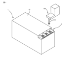
- FIG. 1 is a perspective view showing the appearance of a motor drive device according to this embodiment.
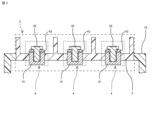
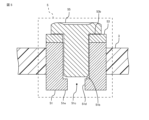
- FIG. 2 is a vertical cross-sectional view showing an example of the terminal block of FIG.
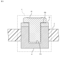
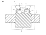
- FIG. 3 is a vertical cross-sectional view showing an example of the terminal portion of FIG.
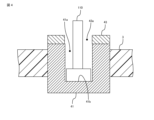
- FIG. 4 is a view showing a second contact surface of the terminal portion of FIG.
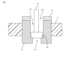
- FIG. 5 is a vertical sectional view showing a first modified example of the terminal portion of FIG.
- FIG. 6 is a diagram showing a first example of the second contact surface of the terminal portion of FIG.
- FIG. 7 is a diagram showing a second example of the second contact surface of the terminal portion of FIG.
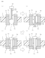
- FIG. 8 is a diagram showing a third example of the second contact surface of the terminal portion of FIG. FIG.
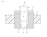
- FIG. 9 is a vertical sectional view showing a second modified example of the terminal portion of FIG.
- FIG. 10 is a diagram showing a first example of the second contact surface of the terminal portion of FIG.
- FIG. 11 is a diagram showing a second example of the second contact surface of the terminal portion of FIG.
- FIG. 12 is a diagram showing a third example of the second contact surface of the terminal portion of FIG.
- FIG. 13 is a perspective view showing the appearance of a motor drive device according to the second embodiment.
- FIG. 14 is a vertical cross-sectional view showing an example of the terminal block of FIG.
- FIG. 15 is a diagram showing a first example of the second contact surface of the terminal portion of FIG.
- FIG. 16 is a diagram showing a second example of the second contact surface of the terminal portion of FIG.
- the motor drive device is intended to drive motors mounted on robot devices, injection molding machines, machine tools, lathes, and the like.
- the motor drive device can convert AC power supplied from an AC power source into DC power using a rectifier, and further convert this DC power into AC power using an inverter, and supply this AC power to the motor as motor drive power.
- the motor drive device has a terminal block that functions as an input/output unit for AC power.
- the terminal block has a terminal portion for electrically connecting a wiring member inside the housing of the motor drive device to a wiring member outside the housing of the motor drive device.
- the wiring member inside the housing of the motor drive device includes electrical components, electronic components, cables, etc. housed inside the housing of the motor drive device.
- the wiring member outside the housing of the motor drive device includes cables, short bars, etc. that are wired outside the motor drive device.
- the motor drive device is characterized in that the contact surface (first contact surface) of the terminal portion that comes into contact with the conductive portion of the wiring member outside the housing of the motor drive device and the contact surface (second contact surface) of the terminal portion that comes into contact with the probe used for the continuity test are electrically conductive and are provided at different positions.
- Fig. 1 is a perspective view showing the external appearance of the motor drive device 1 according to the first embodiment.
- the motor drive device 1 according to the first embodiment has a terminal block 2.
- the terminal block 2 is attached to a housing 10 of the motor drive device 1 by a fastening member such as a screw.
- a fastening member such as a screw.
- the inspection probe 110 of the end effector 100 can be brought into contact with a terminal portion on the surface of the terminal block 2.
- FIG. 2 A longitudinal cross-sectional view showing an example of the terminal block 2 in FIG. 1.
- the terminal block 2 has a non-conductive terminal base 3 and at least one terminal portion 4, here three, held by the terminal base 3.
- the three terminal portions 4 are held by the terminal base 3 so as to be electrically isolated from one another.
- the surface side of the terminal portion 4 is exposed to the outside of the housing 10 of the motor drive device 1 so that an inspection probe 110 used for a continuity inspection can be inserted into a screw hole 41a drilled in the surface of the terminal portion 4.
- the terminal portion 4 has a screw base 41 having a screw hole 41a, a terminal screw 45 inserted into the screw hole 41a, and a conductive plate (conductive plate) 43 arranged on the surface of the screw base 41.
- a through hole 43a that is continuous with the screw hole 41a is formed in the conductive plate 43 so that the terminal screw 45 can be inserted.
- the screw base 41 is conductive and is in a conductive state with the conductive plate 43.
- the conductive plate 43 or the screw base 41 has a connection structure (not shown) to which a conductive portion of a wiring member inside the housing 10 of the motor drive device 1 is electrically connected.
- the wiring member inside the housing 10 of the motor drive device 1 is electrically connected directly to the conductive plate 43 or indirectly via the screw base 41.
- the terminal screw 45 is screwed into the screw hole 41a
- the conductive portion of the wiring member outside the motor drive device 1 is clamped between the screw head of the terminal screw 45 and the conductive plate 43, and is connected to the conductive plate 43.
- the wiring member outside the housing 10 of the motor drive device 1 and the wiring member inside the housing 10 are electrically connected via the terminal portion 4.
- the surface 43b around the through hole 43a of the conductive plate 43 corresponds to the first contact surface of the terminal portion 4 with which the conductive portion of the wiring member outside the motor drive device 1 comes into contact.
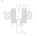
- FIG. 4 is a diagram showing the second contact surface of the terminal portion 4 in FIG. 3.
- the test probe 110 is inserted into the screw hole 41a from the front side of the terminal portion 4 and is brought into contact with the bottom surface 41b of the screw hole 41a.
- the bottom surface 41b of the screw hole 41a is configured to be flat and free of irregularities so that the test probe 110, which has a flat tip shape, can make stable surface contact.
- the bottom surface 41b of the screw hole 41a corresponds to the second contact surface with which the test probe 110 comes into contact.
- the terminal portion 4 is configured so that the first contact surface (surface 43b of the conductive plate 43) with which the conductive portion of the wiring member outside the motor drive device 1 comes into contact and the second contact surface (bottom surface 41b of the screw hole 41a) with which the inspection probe 110 comes into contact are in different positions. This makes it possible to prevent a spark discharge from occurring between the inspection probe 110 and the second contact surface, and to prevent a spark discharge trace from remaining on the second contact surface from changing the contact resistance between the conductive portion of the wiring member outside the motor drive device 1 and the first contact surface.
- the motor drive device 1 even if a spark discharge occurs between the inspection probe 110 and the terminal portion 4 during a continuity test, the traces of the spark discharge can be made less noticeable, and the contact resistance between the conductive portion of the external wiring member and the terminal portion 4, and the contact resistance between the terminal screw 45 and the screw base 41 that constitutes the terminal portion 4 can be prevented from changing.
- This makes it possible to avoid replacement of the terminal block 2 and its components, which are a cause of spark discharge, and therefore eliminates the need to replace these components or perform a continuity test after replacement, thereby preventing an increase in the test time for the continuity test.
- there is no need to check for traces of spark discharge there is no need to provide a process for checking for spark discharge, and the test time for the continuity test can be shortened, resulting in labor savings.
- the structure of the terminal portion is not limited to that shown in FIG. 3.
- a first modified example of the terminal portion will be described with reference to FIGS. 5 and 6.
- the terminal portion 5 of the first modified example is held by the terminal base 3, similar to the terminal portion 4 shown in FIG. 3, and is configured to be capable of electrically connecting the wiring members outside the housing 10 of the motor drive device 1 to the wiring members inside the housing 10.
- the terminal portion 5 of the first modified example provides the same effects as the terminal portion 4 according to the first embodiment.
- the terminal unit 5 is a vertical cross-sectional view showing a first modified example of the terminal unit 4 in FIG. 2.
- the terminal unit 5 according to the first modified example has a screw base 51 having a screw hole 51a, a terminal screw 55 inserted and removed into the screw hole 51a, and a conductive plate (conductive plate) 53 arranged on the surface of the screw base 51.
- the surface 53b around the through hole 53a of the conductive plate 53 corresponds to the first contact surface of the terminal unit 5 with which the wiring member outside the motor drive device 1 comes into contact.
- the conductive plate 53 has a through hole 53a that is continuous with the screw hole 51a so that the terminal screw 55 can be inserted therethrough.
- the screw base 51 is conductive and is in a conductive state with the conductive plate 53.
- a through hole 51c that is continuous with the screw hole 51a and penetrates the screw base 51 is formed on the bottom surface 51b of the screw base 51.
- the through hole 51c has a diameter smaller than the diameter of the screw hole
- FIG. 6 is a diagram showing a first example of the second contact surface of the terminal portion 5 in FIG. 5.
- the inspection probe 110 is inserted into the screw hole 51a from the front side of the terminal portion 5, and is brought into contact with the bottom surface 51b of the screw hole 51a, which is the step between the screw hole 51a and the through hole 51c.
- the bottom surface 51b of the screw hole 51a is configured to be flat and free of irregularities so that the inspection probe 110, which has a flat tip shape, can make stable surface contact.
- the bottom surface 51b of the screw hole 51a corresponds to the second contact surface with which the inspection probe 110 comes into contact.
- FIG. 7 is a diagram showing a second example of the second contact surface of the terminal portion 5 in FIG. 5.
- the inspection probe 120 is inserted from the front surface side of the terminal portion 5 into the screw hole 51a and through hole 51c in that order, and is brought into contact with the inner peripheral surface 51d of the through hole 51c.
- the inner peripheral surface 51d of the through hole 51c is configured to be flat and free of irregularities so that the outer peripheral surface of the inspection probe 120, which has a cylindrical tip shape, can make stable contact.
- the inner peripheral surface 51d of the through hole 51c corresponds to the second contact surface with which the inspection probe 120 comes into contact.
- FIG. 8 is a diagram showing a third example of the second contact surface of the terminal portion 5 in FIG. 5.
- the inspection probe 130 has a pair of rod-shaped probes that can be opened and closed freely. The tips of the probes are bent outward from each other.
- the inspection probe 130 is inserted from the front surface side of the terminal portion 5 through the screw hole 51a and the through hole 51c in this order with the pair of probes closed (FIGS. 8(a) and (b)), and is opened at a position where the tip of the probe passes through the through hole 51c (FIG. 8(c)), and is returned toward the front surface side of the terminal portion 5 with the pair of probes open.
- FIG. 8(a) and (b) the pair of probes closed
- the tips of the pair of probes of the inspection probe 130 are brought into contact with the back surface 51e of the screw base 51.
- the back surface 51e of the screw base 51 is configured to be flat without any irregularities so that the inspection probe 130 can make stable contact. In this way, the back surface 51e around the through hole 51c of the screw base 51 corresponds to the second contact surface with which the inspection probe 130 comes into contact.
- the structure of the terminal portion is not limited to that shown in FIG. 3.
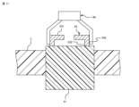
- a second modified example of the terminal portion will be described with reference to FIGS. 9 to 12.
- the terminal portion 6 of the second modified example is held by the terminal base 3, similar to the terminal portion 4 shown in FIG. 3, and is configured to be able to electrically connect the wiring members outside the housing 10 of the motor drive device 1 to the wiring members inside the housing 10.
- the terminal portion 6 of the second modified example provides the same effects as the terminal portion 4 of the first embodiment.
- the terminal portion 6 has a terminal metal fitting 63 having a screw hole 63a, a terminal screw 65 inserted and removed into the screw hole 63a, and a non-conductive metal fitting base 61 that holds the terminal metal fitting 63.
- the terminal metal fitting 63 is a U-shaped metal fitting consisting of a plate-shaped top plate 631 having a screw hole 63a and a pair of side plates 632 continuing from the top plate 631. The terminal metal fitting 63 is held by the metal fitting base 61 so that the side plates 632 protrude toward the front side relative to the metal fitting base 61.
- the terminal metal fitting 63 has a connection structure (not shown) to which a conductive portion of a wiring member inside the housing 10 of the motor drive device 1 is electrically connected. Through this connection structure, the wiring member inside the housing 10 of the motor drive device 1 is directly and electrically connected to the terminal metal fitting 63. On the other hand, the conductive portion of the wiring member outside 10 of motor drive device 1 is clamped between the screw head of terminal screw 65 and the top plate 631 of terminal fitting 63 by screwing terminal screw 65 into screw hole 63a, and is connected to terminal fitting 63. Thus, the wiring member outside housing 10 of motor drive device 1 and the wiring member inside housing 10 are electrically connected via terminal portion 6. Surface 63b of top plate 631 of terminal fitting 63 corresponds to the first contact surface of terminal portion 6 with which the conductive portion of the wiring member outside motor drive device 1 comes into contact.
- FIG. 10 is a diagram showing a first example of the second contact surface of the terminal portion 6 in FIG. 9.
- the inspection probe 110 contacts the outer peripheral surface 63b of the side plate 632 of the terminal fitting 63 from the side of the terminal portion 6.
- the outer peripheral surface 63b of the side plate 632 of the terminal fitting 63 is configured to be flat and free of irregularities so that the inspection probe 110, which has a flat tip shape, can make stable surface contact.
- the outer peripheral surface 63b of the side plate 632 of the terminal fitting 63 corresponds to the second contact surface with which the inspection probe 110 comes into contact.
- FIG. 11 is a diagram showing a second example of the second contact surface of the terminal portion 6 in FIG. 9.
- an inspection probe 140 having a clip-shaped tip contacts the terminal fitting 63 so as to pinch it.
- the outer peripheral surface 63b of the side plate 632 of the terminal fitting 63 is configured to be flat and free of irregularities so that the inspection probe 140 can make stable surface contact.
- the outer peripheral surface 63b of the side plate 632 of the terminal fitting 63 corresponds to the second contact surface with which the inspection probe 140 comes into contact.
- FIG. 12 is a diagram showing a third example of the second contact surface of the terminal portion 6 in FIG. 9.
- the inspection probe 150 is inserted between a pair of side plates 632 from the side of the terminal portion 6 and contacts the back surface 63c of the top plate 631.
- the back surface 63c of the top plate 631 is configured to be flat and free of irregularities so that the inspection probe 150, which has a hook-shaped or plate-shaped tip, can make stable contact.
- the back surface 63c of the top plate 631 corresponds to the second contact surface with which the inspection probe 150 comes into contact.
- the structure of the terminal block is not limited to that of the first embodiment.
- a motor drive device 1' according to a second embodiment will be described with reference to Figs. 13 to 16.
- the motor drive device 1' according to the second embodiment has the same terminal portion as the motor drive device 1 according to the first embodiment.
- the motor drive device 1' according to the second embodiment has the same terminal portion as the terminal portion 5 in Fig. 5, and detailed description of the terminal portion 5 will be omitted.
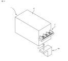
- FIG. 13 is a perspective view showing the appearance of the motor drive device 1' according to the second embodiment.
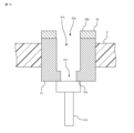
- FIG. 14 is a vertical cross-sectional view showing an example of the terminal block 2' of FIG. 13.
- the terminal block 2' of the motor drive device 1' according to the second embodiment is attached to the side plate of the housing 10' of the motor drive device 1' by a fastening member such as a screw.
- the terminal block 2' is configured so that the test probe 110 used for the continuity test can contact the terminal portion 5 of the terminal block 2' from the back side of the terminal block 2' when attached to the housing 10' of the motor drive device 1'.
- the test probe 110 used for the continuity test can contact the terminal portion 5 of the terminal block 2' from the back side of the terminal block 2' when attached to the housing 10' of the motor drive device 1'.
- the terminal block 2' has a plate-shaped terminal base 3' and a plurality of terminal portions 5 separately held by the terminal base 3'.
- the plurality of terminal portions 5 are attached to the terminal base 3' so that the conductive plate 53 arranged on the front side of the terminal portion 5 and the back side of the screw base 51 corresponding to the back side of the terminal portion 5 are exposed to the outside of the terminal base 3'.
- the surface 53b of the conductive plate 53 corresponds to the first contact surface of the terminal portion 5 with which the conductive portion of the external wiring member of the motor drive device 1' comes into contact.
- FIG. 15 is a diagram showing a first example of the second contact surface of the terminal portion 5 in FIG. 14.
- the inspection probe 110 accesses the motor drive device 1' from the back side and contacts the back surface 51e of the screw base 51.
- the back surface 51e of the screw base 51 is configured to be flat without any irregularities so that the inspection probe 110, which has a flat tip shape, can make stable surface contact.
- the back surface 51e of the screw base 51 corresponds to the second contact surface with which the inspection probe 110 comes into contact. In this case, the through hole 51c of the screw base 51 does not need to be provided.
- FIG. 16 is a diagram showing a second example of the second contact surface of the terminal portion 5 in FIG. 14.
- the inspection probe 120 is accessed from the rear side of the motor drive device 1' and contacts the inner peripheral surface 51d of the through hole 51c of the screw base 51.
- the inner peripheral surface 51d of the through hole 51c is configured to be flat and free of irregularities so that the inspection probe 120, which has a cylindrical tip shape, can make stable contact.
- the inner peripheral surface 51d of the through hole 51c of the screw base 51 corresponds to the second contact surface with which the inspection probe 120 comes into contact.
- the motor drive device 1' according to the second embodiment has the same effect as the first embodiment. That is, according to the motor drive device 1' according to the second embodiment, even if a spark discharge occurs between the test probes 110, 120 and the terminal portion 5 during a continuity test, the trace of the spark discharge only remains on the back surface 51e of the screw base 51 or the inner surface 51d of the through hole 51c of the screw base 51, so that it can be made inconspicuous under normal use conditions, and it is possible to prevent the contact resistance between the conductive portion of the external wiring member and the terminal portion 5, and the contact resistance between the terminal screw 55 constituting the terminal portion 5 and the screw base 51 from changing.
- one important technique is to configure the terminal portion so that the first contact surface of the terminal portion with which the conductive portion of the wiring member external to the motor drive device comes into contact and the second contact surface of the terminal portion with which the inspection probe comes into contact are located at different positions.
- the first and second embodiments several modified examples of the second contact surface have been described.
- the first contact surface can also be provided in a portion according to the structure of the terminal portion, and is not limited to the surface of the conductive plate.
- the terminal portion may be configured such that a conductive screw base also serves as a conductive plate.
- the screw base has a connection structure (not shown) to which a conductive portion of a wiring member inside the housing of the motor drive device is electrically connected.
- the wiring member inside the housing of the motor drive device is directly and electrically connected to the screw base.
- the conductive portion of the wiring member outside the motor drive device is clamped between the screw head of the terminal screw and the screw base by screwing the terminal screw into the screw hole, and is connected to the screw base.
- the wiring member outside the housing of the motor drive device and the wiring member inside the housing are electrically connected via the terminal portion.
- the screw base also serves as a conductive plate
- the surface of the screw base corresponds to the first contact surface of the terminal portion with which the conductive portion of the wiring member outside the motor drive device comes into contact.
- the terminal block is a distinctive feature of the motor drive device according to this embodiment. Therefore, the terminal block provided in the motor drive device according to this embodiment can be used as an independent component, and can also be incorporated into devices other than the motor drive device. Even in such cases, the terminal block achieves the same effects as the motor drive device according to this embodiment.
- the motor drive device 1 has a terminal block 2.
- the terminal block 2 has at least one terminal portion 4.
- the terminal portion 4 has a first contact surface 43b with which a conductive portion of a wiring member comes into contact, and a second contact surface with which an inspection probe comes into contact.
- the first contact surface 43b and the second contact surface are electrically conductive and provided at different positions from each other.
- Appendix 2 In the motor drive device 1 described in Appendix 1, the second contact surface is exposed so that the inspection probe can be accessed from the outside.
- the second contact surface is flat.
- the terminal portion 4 has a conductive screw base 41 having a screw hole 41a, and the second contact surface is a bottom surface 41b of the screw hole 41a.
- the terminal portion 5 has a conductive screw base 51 having a screw hole 51a, a through hole 51c penetrating the screw base 51 is formed in the bottom surface 51b of the screw base 51, and the second contact surface is the inner surface 51d of the through hole 51c.
- the terminal portion 5 has a conductive screw base 51 having a screw hole 51a on its surface, and the second contact surface is the back surface 51e of the screw base 51.
- the terminal portion 6 has a terminal fitting 63 having a screw hole 63a, a terminal screw 65 inserted into the screw hole 63a, and a non-conductive fitting base 61 that holds the terminal fitting 63.
- the terminal fitting 63 is made up of a top plate 631 having the screw hole 63a and a side plate 632 continuing from the top plate 631, and is held by the fitting base 61 such that the side plate 632 protrudes relative to the fitting base 61, and the second contact surface is an outer circumferential surface 63b of the side plate 632.
- the terminal portion 6 includes a terminal fitting 63 having a screw hole 63a, a terminal screw 65 inserted into the screw hole 63a, and a non-conductive metal fitting base 61 that holds the terminal fitting 63.
- the terminal fitting 63 includes a top plate 631 having the screw hole 63a and a side plate 632 continuing from the top plate 631, the top plate 631 is disposed at a position spaced apart from the metal fitting base 61 on the front side, and the second contact surface is a back surface 63c of the top plate 631.
- the terminal block 2 includes at least one terminal portion 4 and a non-conductive terminal seat 3 that separately holds the at least one terminal portion 4.
- the terminal portion 4 includes a screw seat 41 having a screw hole 41a, a terminal screw 45 that is inserted into and removed from the screw hole 41a, and a conductive plate 43 that is disposed on the surface of the screw seat 41.
- the screw seat 41 is conductive.
- the screw seat 41 has a flat surface in addition to the surface, and the flat surface is exposed so that an inspection probe can be accessed from the outside.
Landscapes
- Engineering & Computer Science (AREA)
- Power Engineering (AREA)
- Motor Or Generator Frames (AREA)
Abstract
Description
(付記1)
モータ駆動装置1は端子台2を有する。端子台2は、少なくとも一つの端子部4を有する。端子部4は、配線部材の導電部が接触される第1接触面43bと、検査プローブが接触される第2接触面とを有する。第1接触面43bと第2接触面とは電気的に導通し、互いに異なる位置に設けられる。
(付記2)
付記1に記載のモータ駆動装置1において、第2接触面は、検査プローブが外部からアクセス可能に露出する。
(付記3)
付記1又は付記2に記載のモータ駆動装置1において、第2接触面は平坦である。
(付記4)
付記1乃至付記3のいずれかに記載のモータ駆動装置1において、端子部4は、ネジ孔41aを有する導電性を有するネジ台座41を有し、第2接触面は、ネジ孔41aの底面41bである。
(付記5)
付記1乃至付記3のいずれかに記載のモータ駆動装置1において、端子部5は、ネジ孔51aを有する導電性を有するネジ台座51を有し、ネジ台座51の底面51bにはネジ台座51を貫通する貫通孔51cがあけられ、第2接触面は、貫通孔51cの内周面51dである。
(付記6)
付記1乃至付記3のいずれかに記載のモータ駆動装置1において、端子部5は、表面にネジ孔51aを有する導電性を有するネジ台座51を有し、第2接触面は、ネジ台座51の裏面51eである。
(付記7)
付記1乃至付記3のいずれかに記載のモータ駆動装置1において、端子部6は、ネジ孔63aを有する端子金具63と、ネジ孔63aに挿抜される端子ネジ65と、端子金具63を保持する非導電性の金具台座61と、を有する。端子金具63は、ネジ孔63aを有する天板631と天板631から連続する側板632とからなり、側板632が金具台座61に対して突出するように、金具台座61に保持され、第2接触面は、側板632の外周面63bである。
(付記8)
付記1乃至付記3のいずれかに記載のモータ駆動装置1において、端子部6は、ネジ孔63aを有する端子金具63と、ネジ孔63aに挿抜される端子ネジ65と、端子金具63を保持する非導電性の金具台座61と、を有する。端子金具63は、ネジ孔63aを有する天板631と天板631から連続する側板632とからなり、天板631は金具台座61に対して表面側に離間する位置に配置され、第2接触面は、天板631の裏面63cである。
(付記9)
端子台2は、少なくとも1つの端子部4と少なくとも1つの端子部4を分離保持する非導電性の端子台座3とを具備する。端子部4は、ネジ孔41aを有するネジ台座41と、ネジ孔41aに挿抜される端子ネジ45と、ネジ台座41の表面に配置される導電板43とを有する。ネジ台座41は、導電性を有している。ネジ台座41には、表面以外に平坦面を有し、平坦面は、検査プローブが外部からアクセス可能に露出する。
Claims (9)
- 端子台を有するモータ駆動装置であって、
前記端子台は、少なくとも一つの端子部を有し、
前記端子部は、配線部材の導電部が接触される第1接触面と、検査プローブが接触される第2接触面とを有し、前記第1接触面と前記第2接触面とは電気的に導通し、互いに異なる位置に設けられる、モータ駆動装置。 - 前記第2接触面は、前記検査プローブが外部からアクセス可能に露出する、
請求項1記載のモータ駆動装置。 - 前記第2接触面は平坦である、請求項1又は請求項2に記載のモータ駆動装置。
- 前記端子部は、
ネジ孔があけられた導電性を有するネジ台座を有し、
前記第2接触面は、前記ネジ孔の底面である、
請求項1乃至3のいずれか一項に記載のモータ駆動装置。 - 前記端子部は、
ネジ孔があけられた導電性を有するネジ台座を有し、
前記ネジ台座の底面には前記ネジ台座を貫通する貫通孔があけられ、
前記第2接触面は、前記貫通孔の内周面である、
請求項1乃至3のいずれか一項に記載のモータ駆動装置。 - 前記端子部は、
表面にネジ孔があけられた導電性を有するネジ台座を有し、
前記第2接触面は、前記ネジ台座の裏面である、
請求項1乃至3のいずれか一項に記載のモータ駆動装置。 - 前記端子部は、
ネジ孔を有する端子金具と、
前記ネジ孔に挿抜される端子ネジと、
前記端子金具を保持する非導電性の金具台座と、を有し、
前記端子金具は、前記ネジ孔を有する天板と前記天板から連続する側板とからなり、前記側板が前記金具台座に対して突出するように、前記金具台座に保持され、
前記第2接触面は、前記側板の外周面である、請求項1乃至3のいずれか一項に記載のモータ駆動装置。 - 前記端子部は、
ネジ孔を有する端子金具と、
前記ネジ孔に挿抜される端子ネジと、
前記端子金具を保持する非導電性の金具台座と、を有し、
前記端子金具は、前記ネジ孔を有する天板と前記天板から連続する側板とからなり、前記天板は前記金具台座に対して離間する位置に配置され、
前記第2接触面は、前記天板の裏面である、請求項1乃至3のいずれか一項に記載のモータ駆動装置。 - 少なくとも1つの端子部と、
前記少なくとも1つの端子部を分離保持する非導電性の端子台座と、を具備し、
前記端子部は、
ネジ孔を有するネジ台座と、
前記ネジ孔に挿抜される端子ネジと、
前記ネジ台座の表面に配置される導電板と、を有し、
前記ネジ台座は、導電性を有しており、
前記ネジ台座には、前記表面以外に平坦面を有し、
前記平坦面は、検査プローブが外部からアクセス可能に露出する、
端子台。
Priority Applications (2)
| Application Number | Priority Date | Filing Date | Title |
|---|---|---|---|
| JP2025509414A JPWO2024201800A1 (ja) | 2023-03-29 | 2023-03-29 | |
| PCT/JP2023/012861 WO2024201800A1 (ja) | 2023-03-29 | 2023-03-29 | 端子台及びモータ駆動装置 |
Applications Claiming Priority (1)
| Application Number | Priority Date | Filing Date | Title |
|---|---|---|---|
| PCT/JP2023/012861 WO2024201800A1 (ja) | 2023-03-29 | 2023-03-29 | 端子台及びモータ駆動装置 |
Publications (1)
| Publication Number | Publication Date |
|---|---|
| WO2024201800A1 true WO2024201800A1 (ja) | 2024-10-03 |
Family
ID=92903625
Family Applications (1)
| Application Number | Title | Priority Date | Filing Date |
|---|---|---|---|
| PCT/JP2023/012861 Ceased WO2024201800A1 (ja) | 2023-03-29 | 2023-03-29 | 端子台及びモータ駆動装置 |
Country Status (2)
| Country | Link |
|---|---|
| JP (1) | JPWO2024201800A1 (ja) |
| WO (1) | WO2024201800A1 (ja) |
Citations (6)
| Publication number | Priority date | Publication date | Assignee | Title |
|---|---|---|---|---|
| JPS5278086U (ja) * | 1975-12-09 | 1977-06-10 | ||
| JPS5542217U (ja) * | 1978-09-12 | 1980-03-18 | ||
| JP2011258385A (ja) * | 2010-06-08 | 2011-12-22 | Chugoku Electric Power Co Inc:The | リード用導体接続装置 |
| JP2014002950A (ja) * | 2012-06-19 | 2014-01-09 | Chugoku Electric Power Co Inc:The | 端子台 |
| JP2017045590A (ja) * | 2015-08-26 | 2017-03-02 | 株式会社オートネットワーク技術研究所 | 端子台 |
| JP2019046569A (ja) * | 2017-08-30 | 2019-03-22 | 田淵電機株式会社 | 端子台 |
-
2023
- 2023-03-29 WO PCT/JP2023/012861 patent/WO2024201800A1/ja not_active Ceased
- 2023-03-29 JP JP2025509414A patent/JPWO2024201800A1/ja active Pending
Patent Citations (6)
| Publication number | Priority date | Publication date | Assignee | Title |
|---|---|---|---|---|
| JPS5278086U (ja) * | 1975-12-09 | 1977-06-10 | ||
| JPS5542217U (ja) * | 1978-09-12 | 1980-03-18 | ||
| JP2011258385A (ja) * | 2010-06-08 | 2011-12-22 | Chugoku Electric Power Co Inc:The | リード用導体接続装置 |
| JP2014002950A (ja) * | 2012-06-19 | 2014-01-09 | Chugoku Electric Power Co Inc:The | 端子台 |
| JP2017045590A (ja) * | 2015-08-26 | 2017-03-02 | 株式会社オートネットワーク技術研究所 | 端子台 |
| JP2019046569A (ja) * | 2017-08-30 | 2019-03-22 | 田淵電機株式会社 | 端子台 |
Also Published As
| Publication number | Publication date |
|---|---|
| JPWO2024201800A1 (ja) | 2024-10-03 |
Similar Documents
| Publication | Publication Date | Title |
|---|---|---|
| JP2012044174A (ja) | テスト接触部を有するジャンクションボックス | |
| WO2024201800A1 (ja) | 端子台及びモータ駆動装置 | |
| JP2007304008A (ja) | 基板検査用接触子、基板検査用治具及び基板検査装置 | |
| JP2023080175A (ja) | コネクタ組立方法、車載機器組立方法、コネクタ組立体、車載機器 | |
| JP7342365B2 (ja) | コネクター検査器具、コネクターセット | |
| CN103308728B (zh) | 一种测试治具 | |
| KR102935050B1 (ko) | 방전 가공기용 전원 장치의 진단 장치 | |
| KR101888042B1 (ko) | 와이어 하네스의 회로검사용 검사지그 | |
| JP2020119950A (ja) | 電気機器 | |
| KR200340172Y1 (ko) | 다기능 전력량계 단자커버 | |
| JP4774091B2 (ja) | 電源タワーを具えた多層バーンイン基板構造 | |
| KR20100103182A (ko) | 전기배선의 통전 검사지그 | |
| CN108828389A (zh) | 一种升降式线束检测工作台 | |
| WO2021129307A1 (zh) | 灯模块 | |
| JP6904123B2 (ja) | 検査装置 | |
| CN222125296U (zh) | 一种用于电气参数检测的随行工装机构 | |
| KR102764457B1 (ko) | 커넥터의 성능 시험장치 | |
| JP4730950B2 (ja) | 回路遮断器の端子構造 | |
| JP2000200634A (ja) | 端子盤 | |
| CN216083056U (zh) | 线束类产品电导通测试工装 | |
| CN208548487U (zh) | 插座 | |
| JPH1026646A (ja) | コンタクト装置 | |
| JP2594504Y2 (ja) | 端子装置付電気部品 | |
| CN206460123U (zh) | 一种端子检断导通测试治具 | |
| WO2024224439A1 (ja) | 端子台、モータ駆動装置及びモータ駆動システム |
Legal Events
| Date | Code | Title | Description |
|---|---|---|---|
| 121 | Ep: the epo has been informed by wipo that ep was designated in this application |
Ref document number: 23930438 Country of ref document: EP Kind code of ref document: A1 |
|
| ENP | Entry into the national phase |
Ref document number: 2025509414 Country of ref document: JP Kind code of ref document: A |
|
| WWE | Wipo information: entry into national phase |
Ref document number: 2025509414 Country of ref document: JP |
|
| NENP | Non-entry into the national phase |
Ref country code: DE |
|
| 122 | Ep: pct application non-entry in european phase |
Ref document number: 23930438 Country of ref document: EP Kind code of ref document: A1 |