WO2024201793A1 - 車体後部構造 - Google Patents
車体後部構造 Download PDFInfo
- Publication number
- WO2024201793A1 WO2024201793A1 PCT/JP2023/012825 JP2023012825W WO2024201793A1 WO 2024201793 A1 WO2024201793 A1 WO 2024201793A1 JP 2023012825 W JP2023012825 W JP 2023012825W WO 2024201793 A1 WO2024201793 A1 WO 2024201793A1
- Authority
- WO
- WIPO (PCT)
- Prior art keywords
- rear side
- bottom wall
- side member
- vehicle
- cross member
- Prior art date
- Legal status (The legal status is an assumption and is not a legal conclusion. Google has not performed a legal analysis and makes no representation as to the accuracy of the status listed.)
- Ceased
Links
Images


Classifications
-
- B—PERFORMING OPERATIONS; TRANSPORTING
- B62—LAND VEHICLES FOR TRAVELLING OTHERWISE THAN ON RAILS
- B62D—MOTOR VEHICLES; TRAILERS
- B62D25/00—Superstructure or monocoque structure sub-units; Parts or details thereof not otherwise provided for
- B62D25/08—Front or rear portions
Definitions
- the present invention relates to a rear vehicle body structure.
- a vehicle rear structure in which an arm support bracket is provided on a rear side member, which serves as a framework member constituting the vehicle body, and this arm support bracket supports the front end of a trailing arm that constitutes a torsion beam suspension device.
- the end of the cross member is joined to a portion of the rear side member where the arm support bracket is attached, thereby ensuring rigidity at the joint (see Patent Document 1). Therefore, when a load from the side of the vehicle is input to the rear side member via the arm support bracket, this load is efficiently transmitted from the rear side member to the cross member.
- connection point of the cross member to the rear side member in the vehicle longitudinal direction must be set at a location away from the arm support bracket.
- the present invention has been developed in consideration of the above-mentioned circumstances, and aims to provide a rear body structure that is advantageous in improving handling stability and ride comfort by suppressing displacement of the suspension (trailing arm) in the vehicle width direction.
- one embodiment of the present invention is a vehicle rear structure including a pair of rear side members extending in the fore-and-aft direction of the vehicle with a gap in the vehicle width direction, a cross member extending in the vehicle width direction in front of the pair of rear side members and to which the front ends of the pair of rear side members are connected, and an arm support bracket attached to each of the rear side members near the cross member and supporting the front end of a trailing arm, the front end of the rear side member being provided with a bottom wall flange portion that extends continuously from the bottom wall of the rear side member toward the front of the vehicle and is overlapped and joined from below to the bottom wall of the cross member, the bottom wall flange portion having an extended flange portion that extends inward in the vehicle width direction beyond the inner side wall of the rear side member and is joined to the bottom wall of the cross member.
- the extended flange portion extends inward in the vehicle width direction from the bottom surface of the rear side member and is joined to the bottom surface of the cross member, thereby preventing the rear side member from collapsing (twisting) inward in the vehicle width direction due to a lateral load input to the rear side member via the arm support bracket.
- FIG. 1 is a perspective view of a vehicle rear structure according to an embodiment of the present invention, as viewed from below the vehicle.
- FIG. 2 is a plan view of the vehicle rear body structure according to the embodiment.
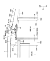
- 1 is a perspective view of a vehicle rear body structure according to an embodiment, showing a state in which a rear side member front portion, a rear side member main body, and an arm support bracket have been removed;
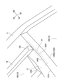
- FIG. 2 is a perspective view of the vehicle rear body structure according to the embodiment, showing a state in which the rear side member front portion is attached and the rear side member main body and the arm support bracket have been removed.
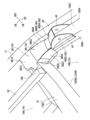
- FIG. 2 is a perspective view of the vehicle rear body structure according to the embodiment, showing a state in which a rear side member front portion, a rear side member main body, and an arm support bracket are attached.
- the symbol FR indicates the front of the vehicle
- the symbol UP indicates the upper side of the vehicle
- the symbol IN indicates the inner side in the vehicle width direction
- the symbol OUT indicates the outer side in the vehicle width direction.
- the rear vehicle body structure of this embodiment is composed of a pair of rear side members 10, a pair of side sills 11, a front cross member 12, a rear cross member 14, a floor panel 16, a pair of floor side members 18, and a torsion beam suspension device 22 including a pair of arm support brackets 20.
- the rear side members 10 are spaced apart in the vehicle width direction and extend in the vehicle front-rear direction.
- Each rear side member 10 includes a bottom wall 1002 and a pair of side walls 1004 extending upward from both sides of the bottom wall 1002 in the vehicle width direction.
- the pair of side sills 11 extend in the front-rear direction of the vehicle on the outer sides of the rear side member 10 in the vehicle width direction, and the rear portions of the side sills 11 are disposed adjacent to the front ends of the rear side members 10 .
- the front cross member 12 extends in the vehicle width direction in front of the pair of rear side members 10, and has front ends of the pair of rear side members 10 joined thereto.
- the front cross member 12 includes a bottom wall 1202 and a pair of side walls 1204 extending upward from both sides of the bottom wall 1202 in the vehicle width direction.
- the rear cross member 14 extends in the vehicle width direction behind the front cross member 12 and has both ends connected to the pair of rear side members 10 .
- the rear cross member 14 includes a bottom wall 1402 and a pair of side walls 1404 extending upward from both sides of the bottom wall 1402 in the vehicle width direction.
- the floor panel 16 includes a front floor panel 16A and a rear floor panel 16B located behind the front floor panel 16A.
- the front floor panel 16A extends from the front cross member 12 toward the front of the vehicle, and the rear floor panel 16B extends from the front cross member 12 toward the rear of the vehicle.
- a pair of floor side members 18 extending in the fore-and-aft direction of the vehicle are provided at locations spaced apart in the vehicle width direction of the front floor panel 16A, and the rear portions of each floor side member 18 are overlapped and joined from below to the bottom wall 1202 of the front cross member 12.
- the pair of floor side members 18 extend in the vehicle fore-and-aft direction, spaced apart in the vehicle width direction, forward of the rear side members 10 in the vehicle fore-and-aft direction. When viewed from the front of the vehicle, the pair of floor side members 18 are located further inward in the vehicle width direction than the pair of rear side members 10 .
- the rear floor panel 16B is provided across the upper ends of a pair of side walls 1004 of each rear side member 10, the upper ends of a pair of side walls 1204 of the front cross member 12, and the upper ends of a pair of side walls 1404 of the rear cross member 14.
- the rear floor panel 16B forms a closed cross-sectional structure between the pair of rear side members 10, the front cross member 12, and the rear cross member 14, respectively.
- the torsion beam suspension device 22 suspends a rear wheel 32 from the rear side member 10, and includes a pair of trailing arms 24, a torsion beam 26, a pair of arm support brackets 20, a pair of coil springs 28, and a pair of shock absorbers 30.
- Each trailing arm 24 has its front end supported by an arm support bracket 20 via a bush 21 so as to be able to swing, and its rear end supports a rear wheel 32 via an axle.
- Each arm support bracket 20 is attached to each rear side member 10 in the vicinity of the rear of the front cross member 12 .
- the torsion beam 26 extends in the vehicle width direction and has both ends connected to the pair of trailing arms 24 .
- Each coil spring 28 is provided between the trailing arm 24 and the rear side member 10 .
- a spring seat 2802 supporting the upper end of the coil spring 28 is provided on the bottom wall 1002 of the rear side member 10, and a spring receiver 2804 supporting the lower end of the coil spring 28 is provided on the trailing arm 24.
- a shock absorber 30 is provided between each trailing arm 24 and the rear side member 10 .
- the front cross member 12 is provided with reinforcements 34 on the inside of both ends in the vehicle width direction.
- the reinforcement 34 is provided extending in the vehicle width direction along a ridge line 1210 of the corner between the bottom wall 1202 of the front cross member 12 and the rear side wall 1204A of the front cross member 12 .
- the reinforcement 34 is formed in an L-shaped cross section, having a lower plate portion 3402 that is overlapped on the bottom wall 1202 of the front cross member 12, and a rear plate portion 3404 that rises from the lower plate portion 3402 and is overlapped on the rear side wall 1204A of the front cross member 12, and is arranged so as to straddle the ridge line 1210 inside the corner of the front cross member 34.
- the lower plate portion 3402 of the reinforcement 34 is overlapped and joined to the rear portion 18A of the floor side member 18 via the bottom wall 1202 of the front cross member 12.
- the rear side member 10 comprises a rear side member main body 36 on which the arm support bracket 20 is provided and which extends in the fore-and-aft direction of the vehicle, and a rear side member front portion 38 which is joined to the front portion of the rear side member main body 36 and connects the rear side member main body 36 and the front cross member 12.
- the rear side member main body 36 and the rear side member front portion 38 each include a bottom wall 3602, 3802 located at the lower portion, and a pair of side walls 3604, 3804 standing upright from both ends of the bottom walls 3602, 3802.
- the front end of the rear side member main body 36 is located at a position separated rearward from the front cross member 12 .
- the front end of the rear side member main body 36 may be joined to the front cross member 12, but positioning the front end of the rear side member main body 36 at a location away from the front cross member 12, as in the present embodiment, is advantageous in terms of reducing the weight of the rear side member main body 36.
- the rear side member main body 36 and the rear side member front portion 38 are joined by overlapping the bottom wall 3602 and the pair of side walls 3604 of the rear side member main body 36 with the outsides of the bottom wall 3802 and the pair of side walls 3804 of the rear side member front portion 38.
- the rear side member front portion 38 is configured to include a bottom wall 3802 and a pair of side walls 3804 , as well as a bottom wall flange portion 3810 and an extension flange portion 3812 .
- the bottom wall 3602 and the pair of side walls 3804 of the rear side member main body 36 are overlapped and joined outwardly to the rear portion of the bottom wall 3802 and the rear portions of the pair of side walls 3804 of the rear side member front portion 38. That is, at the front end of the rear side member 38, a bottom wall flange portion 3810 is provided which extends continuously from the bottom wall 1002 of the rear side member 10 toward the front of the vehicle and is overlapped and joined to the bottom wall 1202 of the front cross member 12 from below.
- the bottom wall flange portion 3810 has an extended flange portion 3812 which extends further inward in the vehicle width direction than the inner side wall 1004 of the rear side member 10 and is overlapped and joined to the bottom wall 1202 of the front cross member 12 from below.
- the extension flange portion 3812 extends toward the inside in the vehicle width direction along the ridge line 1210 of the corner formed by the bottom wall 1202 and the rear side wall 1204A of the front cross member 12.
- the extended flange portion 3812 is connected to the reinforcement 34. More specifically, the extended flange portion 3812 is overlapped and connected to the bottom wall 1202 of the front cross member 12 and the lower plate portion 3402 of the reinforcement 34 in a three-layer configuration.
- the bottom wall flange portion 3810 has approximately the same width in the vehicle width direction as the bottom wall 3802 of the rear side member front portion 38, extends forward from the bottom wall 3802 of the rear side member front portion 38, and is overlapped and joined to the bottom wall 1202 of the front cross member 12 from below.
- the bottom wall flange portion 3810 has a length that extends from the vehicle rear end of the bottom wall 1202 of the front cross member 12 to the middle portion of the bottom wall 1202 of the front cross member 12 in the fore-and-aft direction.
- the extension flange portion 3812 extends from the inner end portion in the vehicle width direction of the bottom wall flange portion 3810 toward the inner side in the vehicle width direction further inward in the vehicle width direction than the contour of the rear side member 10 when viewed from the front of the vehicle.
- the width of the extension flange portion 3812 is formed to be a dimension that reaches the vicinity of the floor side member 18.
- the extended flange portion 3812 has a length that extends from the vehicle rear end of the bottom wall 1202 of the front cross member 12 to the middle portion of the bottom wall 1202 of the front cross member 12 in the fore-and-aft direction.
- each floor side member 18 is overlapped and joined from below to the bottom wall 1202 of the front cross member 12 near the inner side in the vehicle width direction of the extended flange portion 3812.
- reference numeral 3820 indicates a flange which rises inward in the vehicle width direction from the front end of the inner wall 3804A of the pair of side walls 3804 of the rear side member front portion 38 and is joined to the rear side wall 1204A of the front cross member 12
- reference numeral 3822 indicates a flange which rises inward in the vehicle width direction from the upper end of the inner wall 3804A of the rear side member front portion 38 and is joined to the rear floor panel 16B.
- the arm support bracket 20 includes an attachment portion 40 that is attached to the rear side member 10, and a pair of support plate portions 42 that are provided opposite each other and spaced apart in the vehicle width direction.
- the pair of support plate portions 42 are portions that support the bushing 21 provided at the front end of the trailing arm 24 between them.
- the mounting portion 40 includes a rear panel portion 4002 , an intermediate panel portion 4004 , and a front panel portion 4006 .
- the rear panel portion 4002 is located from the front-rear middle portion to the rear portion of the upper ends of the pair of support plate portions 42 .
- the intermediate panel portion 4004 connects the front edges of the pair of support plate portions 42 .
- the front panel portion 4006 extends forward from the upper edge of the intermediate panel portion 4004 .
- the rear panel portion 4002 is joined across from the bottom wall 1002 (the bottom wall 3602 of the side member main body 36 ) of the rear side member 10 to a pair of side walls 1004 (the side walls 3604 of the side member main body 36 ).
- the front panel portion 4006 is overlapped and joined to the bottom wall 1004 of the rear side member 10 (the bottom wall 3604 of the side member main body 36) from below. More specifically, the front panel portion 4006 is overlapped and joined in three layers to the bottom wall 3602 of the rear side member main body 36 and the bottom wall 3802 of the rear side member front portion 38 .
- a bottom wall flange portion 3810 is provided at the front end of the rear side member 10, which extends continuously from the bottom wall 1002 of the rear side member 10 toward the front of the vehicle and is overlapped and joined from below to the bottom wall 1202 of the front cross member 12, and the bottom wall flange portion 3810 has an extended flange portion 3812 which extends further inward in the vehicle width direction than the inner side wall 1004 of the rear side member 10 and is joined to the bottom wall 1202 of the front cross member 12.
- the extended flange portion 3812 extends inward in the vehicle width direction from the bottom wall 1202 of the rear side member 10 and is joined to the bottom wall 1202 of the front cross member 12, which is advantageous in preventing the rear side member 10 from collapsing (twisting) inward in the vehicle width direction due to the lateral load input to the rear side member 10 via the arm support bracket 20. Therefore, suppressing the displacement of the suspension (trailing arm 24) in the vehicle width direction is advantageous in improving the steering stability and ride comfort.
- the extension flange portion 3812 protrudes inward in the vehicle width direction from the vehicle width direction inner end of the bottom wall flange portion 3810 and is overlapped and joined to the bottom wall 1202 of the front cross member 12 from below. That is, both the bottom wall flange portion 3810 and the extension flange portion 3812 have a width in the vehicle front-rear direction and extend in the vehicle width direction.
- both the bottom wall flange portion 3810 and the extended flange portion 3812 extend parallel to each other (in other words, the lateral load is received within the planes of both the bottom wall flange portion 3810 and the extended flange portion 3812) against the lateral load input from the arm support bracket 20 to the rear side member 10, this is advantageous in increasing the rigidity of the rear side member 10 against the lateral load.
- the rear portions of a pair of side sills 11 extending in the vehicle front-rear direction on the outer sides of the rear side member 10 in the vehicle width direction are disposed adjacent to the front end side of the rear side member 10 . Therefore, by having the front end side of the rear side member 10 adjacent to the side sill 11, it is more advantageous in preventing the rear side member 10 from collapsing (twisting) inward in the vehicle width direction due to the lateral load input to the rear side member 10 via the arm support bracket 20, and it is more advantageous in improving handling stability and ride comfort by suppressing displacement of the suspension (trailing arm 24) in the vehicle width direction.
- the extended flange portion 3812 extends toward the inside in the vehicle width direction along the ridge line 1210 of the corner formed by the bottom wall 1202 of the front cross member 12 and the rear side wall 1204A located on the rear side of the front cross member 12. This is advantageous in efficiently transmitting the lateral load input from the rear side member 10 via the arm support bracket 20 to the front cross member 12 via the extended flange portion 3812 to the ridge line 1210 of the corner of the front cross member 12.
- the rigidity of the rear side member 10 against the lateral load input to the rear side member 10 can be increased, which is advantageous in preventing the rear side member 10 from collapsing (twisting) inward in the vehicle width direction, and by suppressing the displacement of the suspension (trailing arm 24) in the vehicle width direction, it is more advantageous in improving handling stability and ride comfort.
- a reinforcement 34 extending in the vehicle width direction along the ridge line 1210 of the corner is provided at the corner between the bottom wall 1202 of the front cross member 12 and the rear side wall 1204A of the front cross member 12, and the extended flange portion 3812 is connected to the reinforcement 34. Therefore, it is more advantageous in efficiently transmitting the lateral load input from the rear side member 10 through the extended flange portion 3812 via the arm support bracket 20 to the reinforcement 34 that reinforces the corner portion (ridge line 1210) of the front cross member 12.
- the rigidity of the rear side member 10 against the lateral load input to the rear side member 10 can be increased, which is advantageous in preventing the rear side member 10 from collapsing (twisting) inward in the vehicle width direction, and by suppressing the displacement of the suspension (trailing arm 24) in the vehicle width direction, it is more advantageous in improving handling stability and ride comfort.
- the reinforcement 34 is formed in an L-shaped cross section having a lower plate portion 3402 that is overlapped on the bottom wall 1202 of the front cross member 12, and a rear plate portion 3404 that rises from the lower plate portion 3402 and is overlapped on the rear side wall 1204A of the front cross member 12, and is arranged so as to straddle the ridge line 1210 inside the corner of the front cross member 12, and the extended flange portion 3810 is overlapped on the bottom wall 1202 and lower plate portion 3404 of the front cross member 12 and joined in a three-layer stack.
- the corners (ridge lines 1210) of the front cross member 12 can be more reliably reinforced with the reinforcement 34, which is even more advantageous in efficiently transmitting the lateral load input from the rear side member 10 via the extended flange portion 3812 to the reinforcement 34.
- This is therefore even more advantageous in increasing the rigidity of the rear side member 10 against lateral loads input to the rear side member 10, and is even more advantageous in preventing the rear side member 10 from collapsing (twisting) inward in the vehicle width direction, and is even more advantageous in improving handling stability and ride comfort by suppressing displacement of the suspension (trailing arm 24) in the vehicle width direction.
- a pair of floor side members 18 are provided which extend in the fore-and-aft direction of the vehicle and are spaced apart in the vehicle width direction at a location forward of the rear side member 10 and on the inner side of the rear side member 10 in the vehicle width direction, and the rear portions of each floor side member 18 are overlapped and joined from below to the bottom wall 1202 of the front cross member 12, and the reinforcement 34 is connected to the rear portions 18A of the floor side members 18.
- the lateral load input to the rear side member 10 can be efficiently transmitted via the reinforcement 34 to the floor side member 18 in addition to the front cross member 12, which is more advantageous in increasing the rigidity of the rear side member 10, and by suppressing the displacement of the suspension (trailing arm 24) in the vehicle width direction, it is more advantageous in improving handling stability and ride comfort.
- the front panel portion 4006 of the mounting portion 40 of the arm support bracket 20 is overlapped with the bottom wall 3602 of the rear side member main body 36 and the bottom wall 3802 of the rear side member front portion 38, and joined in three layers. This is even more advantageous in efficiently transmitting the lateral load input from the arm support bracket 20 to the rear side member 10 to the front cross member 12 .
- the mounting rigidity of the arm support bracket 20 can be increased, and by suppressing displacement of the suspension (trailing arm 24) in the vehicle width direction, it is more advantageous in improving handling stability and ride comfort.
- the rear side member 10 is constituted by the rear side member main body 36 and the rear side member front portion 38, but the rear side member 10 may be constituted integrally.
- the rear side member 10 is constructed of a rear side member main body 36 extending in the fore-and-aft direction of the vehicle, and a rear side member front portion 38 joined to the front portion of the rear side member main body 36, as in the present embodiment, changing the plate thickness of both portions is advantageous in improving handling stability and ride comfort without increasing the weight of the vehicle body. That is, the load input laterally from the arm support bracket 20 to the rear side member 10 is transmitted to the front cross member 12 via the bottom wall flange portion 3810 and the extension flange portion 3812 of the rear side member front portion 38 .
Landscapes
- Engineering & Computer Science (AREA)
- Chemical & Material Sciences (AREA)
- Combustion & Propulsion (AREA)
- Transportation (AREA)
- Mechanical Engineering (AREA)
- Body Structure For Vehicles (AREA)
Abstract
サスペンション(トレーリングアーム)の車幅方向での変位を抑制することで操縦安定性および乗り心地の向上を図る。 リアサイドメンバ10の前端には、リアサイドメンバ10の底壁から連続して車両前方に延設され、前部クロスメンバ12の底壁1202に下方から重ね合わされて接合される底壁フランジ部3810が設けられ、底壁フランジ部3810は、リアサイドメンバ10の車幅方向内側の側壁よりも車幅方向内側に延長されて前部クロスメンバ12の底壁12に接合される延長フランジ部3812を有している。
Description
本発明は車体後部構造に関する。
車体を構成する骨格部材としてのリアサイドメンバにアーム支持用ブラケットを設け、このアーム支持用ブラケットによってトーションビーム式のサスペンション装置を構成するトレーリングアームの前端を支持する車体後部構造が知られている。
この車体後部構造では、アーム支持用ブラケットが取り付けられたリアサイドメンバの箇所にクロスメンバの端部が結合されることで結合箇所の剛性が確保されている(特許文献1参照)。
したがって、車両に対して横方向からの荷重がアーム支持用ブラケットを介してリアサイドメンバに入力した場合、この荷重はリアサイドメンバからクロスメンバに効率よく伝達される。
この車体後部構造では、アーム支持用ブラケットが取り付けられたリアサイドメンバの箇所にクロスメンバの端部が結合されることで結合箇所の剛性が確保されている(特許文献1参照)。
したがって、車両に対して横方向からの荷重がアーム支持用ブラケットを介してリアサイドメンバに入力した場合、この荷重はリアサイドメンバからクロスメンバに効率よく伝達される。
しかしながら、レイアウトの都合上、車両前後方向においてリアサイドメンバに対するクロスメンバの結合箇所をアーム支持用ブラケットから離れた箇所に設定しなければならない場合がある。
この場合、アーム支持用ブラケットが取り付けられるリアサイドメンバの箇所の剛性を確保する上で不利となり、アーム支持用ブラケットを介してリアサイドメンバに入力する横方向の荷重によりリアサイドメンバが車幅方向内側への倒れる(捻じれる)ことから、サスペンション(トレーリングアーム)の車幅方向での変位が生じるため、車両の操縦安定性および乗り心地を確保する上で改善の余地がある。
本発明は、上記事情に鑑みなされたものであり、サスペンション(トレーリングアーム)の車幅方向での変位を抑制することで操縦安定性および乗り心地の向上を図る上で有利な車体後部構造を提供することを目的とする。
この場合、アーム支持用ブラケットが取り付けられるリアサイドメンバの箇所の剛性を確保する上で不利となり、アーム支持用ブラケットを介してリアサイドメンバに入力する横方向の荷重によりリアサイドメンバが車幅方向内側への倒れる(捻じれる)ことから、サスペンション(トレーリングアーム)の車幅方向での変位が生じるため、車両の操縦安定性および乗り心地を確保する上で改善の余地がある。
本発明は、上記事情に鑑みなされたものであり、サスペンション(トレーリングアーム)の車幅方向での変位を抑制することで操縦安定性および乗り心地の向上を図る上で有利な車体後部構造を提供することを目的とする。
上記目的を達成するために、本発明の一実施の形態は、車幅方向に間隔をおいて車両前後方向に延在する一対のリアサイドメンバと、前記一対のリアサイドメンバの車両前方で車幅方向に延在し前記一対のリアサイドメンバの前端が結合されるクロスメンバと、前記クロスメンバの近傍の前記各リアサイドメンバにそれぞれ取り付けられトレーリングアームの前端を支持するアーム支持用ブラケットと、を備える車体後部構造であって、前記リアサイドメンバの前端には、前記リアサイドメンバの底壁から連続して車両前方に延設され、前記クロスメンバの底壁に下方から重ね合わされて接合される底壁フランジ部が設けられ、前記底壁フランジ部は、前記リアサイドメンバの車幅方向内側の側壁よりも車幅方向内側に延長されて前記クロスメンバの底壁に接合される延長フランジ部を有することを特徴とする。
本発明の一実施の形態によれば、延長フランジ部がリアサイドメンバの底面より車幅方向内側に延在してクロスメンバの底面に接合されるので、アーム支持用ブラケットを介してリアサイドメンバに入力する横方向の荷重によりリアサイドメンバが車幅方向内側への倒れる(捻じれる)ことを抑制することができる。
そのため、サスペンション(トレーリングアーム)の車幅方向での変位を抑制することができるので操縦安定性および乗り心地を向上させる上で有利となる。
そのため、サスペンション(トレーリングアーム)の車幅方向での変位を抑制することができるので操縦安定性および乗り心地を向上させる上で有利となる。
以下、本発明の実施の形態について図面を参照して説明する。
なお、以下の図面において符号FRは車両前方、符号UPは車両上方、符号INは車幅方向内方、符号OUTは車幅方向外方を示す。
図1、図2に示すように、本実施の形態の車体後部構造は、一対のリアサイドメンバ10と、一対のサイドシル11と、前部クロスメンバ12と、後部クロスメンバ14と、フロアパネル16と、一対のフロアサイドメンバ18と、一対のアーム支持用ブラケット20を含むトーションビーム式サスペンション装置22とを含んで構成されている。
各リアサイドメンバ10は、車幅方向に間隔をおいて設けられ、車両前後方向に延在している。
各リアサイドメンバ10は、底壁1002と、底壁1002の車幅方向両側から上方に立設された一対の側壁1004とを備えている。
一対のサイドシル11は、リアサイドメンバ10の車幅方向外側で車両前後方向に延在し、サイドシル11の後部は、リアサイドメンバ10の前端側と隣接して配置されている。
なお、以下の図面において符号FRは車両前方、符号UPは車両上方、符号INは車幅方向内方、符号OUTは車幅方向外方を示す。
図1、図2に示すように、本実施の形態の車体後部構造は、一対のリアサイドメンバ10と、一対のサイドシル11と、前部クロスメンバ12と、後部クロスメンバ14と、フロアパネル16と、一対のフロアサイドメンバ18と、一対のアーム支持用ブラケット20を含むトーションビーム式サスペンション装置22とを含んで構成されている。
各リアサイドメンバ10は、車幅方向に間隔をおいて設けられ、車両前後方向に延在している。
各リアサイドメンバ10は、底壁1002と、底壁1002の車幅方向両側から上方に立設された一対の側壁1004とを備えている。
一対のサイドシル11は、リアサイドメンバ10の車幅方向外側で車両前後方向に延在し、サイドシル11の後部は、リアサイドメンバ10の前端側と隣接して配置されている。
前部クロスメンバ12は、一対のリアサイドメンバ10の車両前方で車幅方向に延在し、一対のリアサイドメンバ10の前端が結合されている。
前部クロスメンバ12は、底壁1202と、底壁1202の車幅方向両側から上方に立設された一対の側壁1204とを備えている。
後部クロスメンバ14は、前部クロスメンバ12の後方で車幅方向に延在し、その両端が一対のリアサイドメンバ10に結合されている。
後部クロスメンバ14は、底壁1402と、底壁1402の車幅方向両側から上方に立設された一対の側壁1404とを備えている。
前部クロスメンバ12は、底壁1202と、底壁1202の車幅方向両側から上方に立設された一対の側壁1204とを備えている。
後部クロスメンバ14は、前部クロスメンバ12の後方で車幅方向に延在し、その両端が一対のリアサイドメンバ10に結合されている。
後部クロスメンバ14は、底壁1402と、底壁1402の車幅方向両側から上方に立設された一対の側壁1404とを備えている。
フロアパネル16は、フロントフロアパネル16Aと、その後方に位置するリアフロアパネル16Bとを含んで構成されている。
フロントフロアパネル16Aは、前部クロスメンバ12から車両前方に延在し、リアフロアパネル16Bは前部クロスメンバ12から車両後方に延在している。
フロントフロアパネル16Aの車幅方向に間隔をおいた箇所に、車両前後方向に延在する一対のフロアサイドメンバ18が設けられ、各フロアサイドメンバ18の後部は前部クロスメンバ12の底壁1202に下方から重ね合わされて接合されている。
したがって、一対のフロアサイドメンバ18は、車両前後方向においてリアサイドメンバ10よりも前方で車幅方向に間隔をおき車両前後方向に延在している。
車両の前方から見て、一対のフロアサイドメンバ18は、一対のリアサイドメンバ10よりも車幅方向内側に位置している。
フロントフロアパネル16Aは、前部クロスメンバ12から車両前方に延在し、リアフロアパネル16Bは前部クロスメンバ12から車両後方に延在している。
フロントフロアパネル16Aの車幅方向に間隔をおいた箇所に、車両前後方向に延在する一対のフロアサイドメンバ18が設けられ、各フロアサイドメンバ18の後部は前部クロスメンバ12の底壁1202に下方から重ね合わされて接合されている。
したがって、一対のフロアサイドメンバ18は、車両前後方向においてリアサイドメンバ10よりも前方で車幅方向に間隔をおき車両前後方向に延在している。
車両の前方から見て、一対のフロアサイドメンバ18は、一対のリアサイドメンバ10よりも車幅方向内側に位置している。
リアフロアパネル16Bは、各リアサイドメンバ10の一対の側壁1004の上端と、前部クロスメンバ12の一対の側壁1204の上端と、後部クロスメンバ14の一対の側壁1404の上端とにわたって設けられている。
リアフロアパネル16Bは、一対のリアサイドメンバ10、前部クロスメンバ12、後部クロスメンバ14との間にそれぞれ閉断面構造を形成している。
リアフロアパネル16Bは、一対のリアサイドメンバ10、前部クロスメンバ12、後部クロスメンバ14との間にそれぞれ閉断面構造を形成している。
図1に示すように、トーションビーム式サスペンション装置22は、リアサイドメンバ10に対して後輪32を懸架するものであり、一対のトレーリングアーム24と、トーションビーム26と、一対のアーム支持用ブラケット20と、一対のコイルスプリング28と、一対のショックアブソーバ30とを含んで構成されている。
各トレーリングアーム24は、その前端がアーム支持用ブラケット20にブッシュ21を介して揺動可能に支持され、その後端が車軸を介して後輪32を支持している。
各アーム支持用ブラケット20は、前部クロスメンバ12の後方の近傍の各リアサイドメンバ10にそれぞれ取り付けられている。
トーションビーム26は、車幅方向に延在しその両端が一対のトレーリングアーム24に連結されている。
各コイルスプリング28は、トレーリングアーム24とリアサイドメンバ10との間にそれぞれ設けられている。
コイルスプリング28の上端を支持するスプリングシート2802が、リアサイドメンバ10の底壁1002に設けられ、コイルスプリング28の下端を支持するスプリング受け2804がトレーリングアーム24に設けられている。
また、トレーリングアーム24とリアサイドメンバ10との間にショックアブソーバ30がそれぞれ設けられている。
各トレーリングアーム24は、その前端がアーム支持用ブラケット20にブッシュ21を介して揺動可能に支持され、その後端が車軸を介して後輪32を支持している。
各アーム支持用ブラケット20は、前部クロスメンバ12の後方の近傍の各リアサイドメンバ10にそれぞれ取り付けられている。
トーションビーム26は、車幅方向に延在しその両端が一対のトレーリングアーム24に連結されている。
各コイルスプリング28は、トレーリングアーム24とリアサイドメンバ10との間にそれぞれ設けられている。
コイルスプリング28の上端を支持するスプリングシート2802が、リアサイドメンバ10の底壁1002に設けられ、コイルスプリング28の下端を支持するスプリング受け2804がトレーリングアーム24に設けられている。
また、トレーリングアーム24とリアサイドメンバ10との間にショックアブソーバ30がそれぞれ設けられている。
次に、前部クロスメンバ12、リアサイドメンバ10、アーム支持用ブラケット20について具体的に説明する。
図3に示すように、前部クロスメンバ12は、その車幅方向の両端の内部にリンフォース34が設けられている。
詳細に説明すると、リンフォース34は、前部クロスメンバ12の底壁1202と前部クロスメンバ12の後側壁1204Aとの角部の稜線1210に沿って車幅方向に延在して設けられている。
リンフォース34は、前部クロスメンバ12の底壁1202に重ねられる下板部3402と、下板部3402から起立して前部クロスメンバ12の後側壁1204Aに重ねられる後板部3404とを有した断面L字状に形成され、前部クロスメンバ34の角部の内側で稜線1210を跨ぐように設けられている。
また、リンフォース34の下板部3402は、前部クロスメンバ12の底壁1202を介してフロアサイドメンバ18の後部18Aに重ね合わされて結合されている。
図3に示すように、前部クロスメンバ12は、その車幅方向の両端の内部にリンフォース34が設けられている。
詳細に説明すると、リンフォース34は、前部クロスメンバ12の底壁1202と前部クロスメンバ12の後側壁1204Aとの角部の稜線1210に沿って車幅方向に延在して設けられている。
リンフォース34は、前部クロスメンバ12の底壁1202に重ねられる下板部3402と、下板部3402から起立して前部クロスメンバ12の後側壁1204Aに重ねられる後板部3404とを有した断面L字状に形成され、前部クロスメンバ34の角部の内側で稜線1210を跨ぐように設けられている。
また、リンフォース34の下板部3402は、前部クロスメンバ12の底壁1202を介してフロアサイドメンバ18の後部18Aに重ね合わされて結合されている。
図4、図5に示すように、リアサイドメンバ10は、アーム支持用ブラケット20が設けられ車両前後方向に延在するリアサイドメンバ本体36と、リアサイドメンバ本体36の前部に結合されてリアサイドメンバ本体36と前部クロスメンバ12とを連結するリアサイドメンバ前部38とを備えている。
リアサイドメンバ本体36と、リアサイドメンバ前部38とは、それぞれ下部に位置する底壁3602、3802と、底壁3602、3802の両端から起立する一対の側壁3604、3804とを備えている。
リアサイドメンバ本体36の前端は前部クロスメンバ12の後方に離れた箇所に位置している。
なお、リアサイドメンバ本体36の前端を前部クロスメンバ12に結合しても良いが、本実施の形態のようにリアサイドメンバ本体36の前端を前部クロスメンバ12の後方に離れた箇所に位置させると、リアサイドメンバ本体36の軽量化を図る上で有利となる。
リアサイドメンバ本体36とリアサイドメンバ前部38とは、リアサイドメンバ前部38の底壁3802と一対の側壁3804の外側にリアサイドメンバ本体36の底壁3602と一対の側壁3604とが重ね合わされて接合されている。
リアサイドメンバ本体36と、リアサイドメンバ前部38とは、それぞれ下部に位置する底壁3602、3802と、底壁3602、3802の両端から起立する一対の側壁3604、3804とを備えている。
リアサイドメンバ本体36の前端は前部クロスメンバ12の後方に離れた箇所に位置している。
なお、リアサイドメンバ本体36の前端を前部クロスメンバ12に結合しても良いが、本実施の形態のようにリアサイドメンバ本体36の前端を前部クロスメンバ12の後方に離れた箇所に位置させると、リアサイドメンバ本体36の軽量化を図る上で有利となる。
リアサイドメンバ本体36とリアサイドメンバ前部38とは、リアサイドメンバ前部38の底壁3802と一対の側壁3804の外側にリアサイドメンバ本体36の底壁3602と一対の側壁3604とが重ね合わされて接合されている。
リアサイドメンバ前部38は、底壁3802と一対の側壁3804とに加え、底壁フランジ部3810と、延長フランジ部3812とを含んで構成されている。
リアサイドメンバ前部38の底壁3802の後部と一対の側壁3804の後部には上述のようにリアサイドメンバ本体36の底壁3602と一対の側壁3804が外側に重ね合わされて接合されている。
すなわち、リアサイドメンバ38の前端には、リアサイドメンバ10の底壁1002から連続して車両前方に延設され、前部クロスメンバ12の底壁1202に下方から重ね合わされて接合される底壁フランジ部3810が設けられている。
底壁フランジ部3810は、リアサイドメンバ10の車幅方向内側の側壁1004よりも車幅方向内側に延長されて前部クロスメンバ12の底壁1202に底壁1202に下方から重ね合わされて接合される延長フランジ部3812を有している。
延長フランジ部3812は、前部クロスメンバ12の底壁1202と後側壁1204Aとで形成される角部の稜線1210に沿って車幅方向内側向かって延在されている。
図4に示すように、延長フランジ部3812は、リンフォース34と結合されており、詳細に説明すると、延長フランジ部3812は、前部クロスメンバ12の底壁1202とリンフォース34の下板部3402に重ね合わされ3枚重ねで結合されている。
底壁フランジ部3810は、リアサイドメンバ前部38の底壁3802とほぼ同じ車幅方向の幅を有し、リアサイドメンバ前部38の底壁3802から前方に延在し、前部クロスメンバ12の底壁1202に下方から重ね合わされ接合されている。
底壁フランジ部3810は、前部クロスメンバ12の底壁1202の車両後端から前部クロスメンバ12の底壁1202の前後方向の中間部を超える長さを有している。
延長フランジ部3812は、底壁フランジ部3810の車幅方向内側端部から、車両前方から見てリアサイドメンバ10の輪郭よりも車幅方向内側に延在している。
延長フランジ部3812の幅は、フロアサイドメンバ18の近傍に至る寸法で形成されている。
また、延長フランジ部3812は、前部クロスメンバ12の底壁1202の車両後端から前部クロスメンバ12の底壁1202の前後方向の中間部に至る長さを有している。
また、各フロアサイドメンバ18の後部18Aは、延長フランジ部3812の車幅方向内側の近傍で前部クロスメンバ12の底壁1202に下方から重ね合わされ接合されている。
図中、符号3820はリアサイドメンバ前部38の一対の側壁3804のうち車幅方向内側の内側壁3804Aの前端から車幅方向内側に起立して前部クロスメンバ12の後側壁1204Aに接合されるフランジを示し、符号3822はリアサイドメンバ前部38の内側壁3804Aの上端から車幅方向内側に起立してリアフロアパネル16Bに接合されるフランジを示す。
リアサイドメンバ前部38の底壁3802の後部と一対の側壁3804の後部には上述のようにリアサイドメンバ本体36の底壁3602と一対の側壁3804が外側に重ね合わされて接合されている。
すなわち、リアサイドメンバ38の前端には、リアサイドメンバ10の底壁1002から連続して車両前方に延設され、前部クロスメンバ12の底壁1202に下方から重ね合わされて接合される底壁フランジ部3810が設けられている。
底壁フランジ部3810は、リアサイドメンバ10の車幅方向内側の側壁1004よりも車幅方向内側に延長されて前部クロスメンバ12の底壁1202に底壁1202に下方から重ね合わされて接合される延長フランジ部3812を有している。
延長フランジ部3812は、前部クロスメンバ12の底壁1202と後側壁1204Aとで形成される角部の稜線1210に沿って車幅方向内側向かって延在されている。
図4に示すように、延長フランジ部3812は、リンフォース34と結合されており、詳細に説明すると、延長フランジ部3812は、前部クロスメンバ12の底壁1202とリンフォース34の下板部3402に重ね合わされ3枚重ねで結合されている。
底壁フランジ部3810は、リアサイドメンバ前部38の底壁3802とほぼ同じ車幅方向の幅を有し、リアサイドメンバ前部38の底壁3802から前方に延在し、前部クロスメンバ12の底壁1202に下方から重ね合わされ接合されている。
底壁フランジ部3810は、前部クロスメンバ12の底壁1202の車両後端から前部クロスメンバ12の底壁1202の前後方向の中間部を超える長さを有している。
延長フランジ部3812は、底壁フランジ部3810の車幅方向内側端部から、車両前方から見てリアサイドメンバ10の輪郭よりも車幅方向内側に延在している。
延長フランジ部3812の幅は、フロアサイドメンバ18の近傍に至る寸法で形成されている。
また、延長フランジ部3812は、前部クロスメンバ12の底壁1202の車両後端から前部クロスメンバ12の底壁1202の前後方向の中間部に至る長さを有している。
また、各フロアサイドメンバ18の後部18Aは、延長フランジ部3812の車幅方向内側の近傍で前部クロスメンバ12の底壁1202に下方から重ね合わされ接合されている。
図中、符号3820はリアサイドメンバ前部38の一対の側壁3804のうち車幅方向内側の内側壁3804Aの前端から車幅方向内側に起立して前部クロスメンバ12の後側壁1204Aに接合されるフランジを示し、符号3822はリアサイドメンバ前部38の内側壁3804Aの上端から車幅方向内側に起立してリアフロアパネル16Bに接合されるフランジを示す。
図5に示すように、アーム支持用ブラケット20は、リアサイドメンバ10に取り付けられる取り付け部40と、車幅方向に間隔をおいて対向して設けられた一対の支持板部42とを含んで構成されている。
一対の支持板部42は、それらの間にトレーリングアーム24の前端に設けられたブッシュ21を支持する箇所である。
取り付け部40は、後パネル部4002と、中間パネル部4004と、前パネル部4006とを含んで構成されている。
後パネル部4002は、一対の支持板部42の上端の前後中間部から後部の箇所に位置している。
中間パネル部4004は、一対の支持板部42の前縁を接続している。
前パネル部4006は、中間パネル部4004の上縁から前方に延在している。
後パネル部4002は、リアサイドメンバ10の底壁1002(サイドメンバ本体36の底壁3602)から一対の側壁1004(サイドメンバ本体36の側壁3604)にわたって接合されている。
前パネル部4006は、リアサイドメンバ10の底壁1004(サイドメンバ本体36の底壁3604)に下方から重ね合わされて接合されている。
詳細に説明すると、前パネル部4006は、リアサイドメンバ本体36の底壁3602と、リアサイドメンバ前部38の底壁3802とに重ね合わされ3枚重ねで接合されている。
一対の支持板部42は、それらの間にトレーリングアーム24の前端に設けられたブッシュ21を支持する箇所である。
取り付け部40は、後パネル部4002と、中間パネル部4004と、前パネル部4006とを含んで構成されている。
後パネル部4002は、一対の支持板部42の上端の前後中間部から後部の箇所に位置している。
中間パネル部4004は、一対の支持板部42の前縁を接続している。
前パネル部4006は、中間パネル部4004の上縁から前方に延在している。
後パネル部4002は、リアサイドメンバ10の底壁1002(サイドメンバ本体36の底壁3602)から一対の側壁1004(サイドメンバ本体36の側壁3604)にわたって接合されている。
前パネル部4006は、リアサイドメンバ10の底壁1004(サイドメンバ本体36の底壁3604)に下方から重ね合わされて接合されている。
詳細に説明すると、前パネル部4006は、リアサイドメンバ本体36の底壁3602と、リアサイドメンバ前部38の底壁3802とに重ね合わされ3枚重ねで接合されている。
次に、作用効果について説明する。
本実施の形態では、リアサイドメンバ10の前端には、リアサイドメンバ10の底壁1002から連続して車両前方に延設され、前部クロスメンバ12の底壁1202に下方から重ね合わされて接合される底壁フランジ部3810が設けられ、底壁フランジ部3810は、リアサイドメンバ10の車幅方向内側の側壁1004よりも車幅方向内側に延長されて前部クロスメンバ12の底壁12に接合される延長フランジ部3812を有している。
そのため、延長フランジ部3812がリアサイドメンバ10の底壁1202より車幅方向内側に延在して前部クロスメンバ12の底壁1202に接合されるので、アーム支持用ブラケット20を介してリアサイドメンバ10に入力する横方向の荷重によりリアサイドメンバ10が車幅方向内側への倒れる(捻じれる)ことを抑制する上で有利となる。
したがって、サスペンション(トレーリングアーム24)の車幅方向での変位を抑制することにより、操縦安定性および乗り心地を向上させる上で有利となる。
また、アーム支持用ブラケット20が前部クロスメンバ12から車両前後方向に離間している場合であっても、リアサイドメンバ10から前部クロスメンバ12に効率よく荷重を伝達する上で有利となり、操縦安定性および乗り心地の向上を図る上で有利となる。
言い換えると、延長フランジ部3812が底壁フランジ部3810の車幅方向内側端部から車幅方向内側に突出して前部クロスメンバ12の底壁1202に下方から重ね合わされ接合されている。
すなわち、底壁フランジ部3810と延長フランジ部3812とは共に車両前後方向の幅を有して車幅方向に延在している。
したがって、アーム支持用ブラケット20からリアサイドメンバ10に入力する横方向の荷重に対して底壁フランジ部3810と延長フランジ部3812の双方が平行に延在していることから(言い換えると、横方向の荷重を底壁フランジ部3810と延長フランジ部3812の双方の面内で受けることから)、横方向の荷重に対するリアサイドメンバ10の剛性を高める上で有利となる。
本実施の形態では、リアサイドメンバ10の前端には、リアサイドメンバ10の底壁1002から連続して車両前方に延設され、前部クロスメンバ12の底壁1202に下方から重ね合わされて接合される底壁フランジ部3810が設けられ、底壁フランジ部3810は、リアサイドメンバ10の車幅方向内側の側壁1004よりも車幅方向内側に延長されて前部クロスメンバ12の底壁12に接合される延長フランジ部3812を有している。
そのため、延長フランジ部3812がリアサイドメンバ10の底壁1202より車幅方向内側に延在して前部クロスメンバ12の底壁1202に接合されるので、アーム支持用ブラケット20を介してリアサイドメンバ10に入力する横方向の荷重によりリアサイドメンバ10が車幅方向内側への倒れる(捻じれる)ことを抑制する上で有利となる。
したがって、サスペンション(トレーリングアーム24)の車幅方向での変位を抑制することにより、操縦安定性および乗り心地を向上させる上で有利となる。
また、アーム支持用ブラケット20が前部クロスメンバ12から車両前後方向に離間している場合であっても、リアサイドメンバ10から前部クロスメンバ12に効率よく荷重を伝達する上で有利となり、操縦安定性および乗り心地の向上を図る上で有利となる。
言い換えると、延長フランジ部3812が底壁フランジ部3810の車幅方向内側端部から車幅方向内側に突出して前部クロスメンバ12の底壁1202に下方から重ね合わされ接合されている。
すなわち、底壁フランジ部3810と延長フランジ部3812とは共に車両前後方向の幅を有して車幅方向に延在している。
したがって、アーム支持用ブラケット20からリアサイドメンバ10に入力する横方向の荷重に対して底壁フランジ部3810と延長フランジ部3812の双方が平行に延在していることから(言い換えると、横方向の荷重を底壁フランジ部3810と延長フランジ部3812の双方の面内で受けることから)、横方向の荷重に対するリアサイドメンバ10の剛性を高める上で有利となる。
また、本実施の形態では、リアサイドメンバ10の車幅方向外側で車両前後方向に延在される一対のサイドシル11の後部がリアサイドメンバ10の前端側と隣接して配置されている。
したがって、リアサイドメンバ10の前端側が、サイドシル11と隣接する事で、アーム支持用ブラケット20を介してリアサイドメンバ10に入力する横方向の荷重によってリアサイドメンバ10が車幅方向内側へ倒れる(捻じれる)ことを抑制する上でより有利となり、サスペンション(トレーリングアーム24)の車幅方向での変位を抑制することで操縦安定性および乗り心地を向上させる上でより有利となる。
したがって、リアサイドメンバ10の前端側が、サイドシル11と隣接する事で、アーム支持用ブラケット20を介してリアサイドメンバ10に入力する横方向の荷重によってリアサイドメンバ10が車幅方向内側へ倒れる(捻じれる)ことを抑制する上でより有利となり、サスペンション(トレーリングアーム24)の車幅方向での変位を抑制することで操縦安定性および乗り心地を向上させる上でより有利となる。
また、本実施の形態では、延長フランジ部3812は、前部クロスメンバ12の底壁1202と前部クロスメンバ12の車両後方側に位置する後側壁1204Aとで形成される角部の稜線1210に沿って車幅方向内側向かって延在されている。
そのため、アーム支持用ブラケット20を介してリアサイドメンバ10から延長フランジ部3812を介して前部クロスメンバ12に入力される横方向の荷重を前部クロスメンバ12の角部の稜線1210に効率よく伝達する上で有利となる。
したがって、リアサイドメンバ10に入力する横方向の荷重に対してリアサイドメンバ10の剛性をより高めることができ、リアサイドメンバ10が車幅方向内側への倒れる(捻じれる)ことを抑制する上で有利となり、サスペンション(トレーリングアーム24)の車幅方向での変位を抑制することにより、操縦安定性および乗り心地を向上させる上でより有利となる。
そのため、アーム支持用ブラケット20を介してリアサイドメンバ10から延長フランジ部3812を介して前部クロスメンバ12に入力される横方向の荷重を前部クロスメンバ12の角部の稜線1210に効率よく伝達する上で有利となる。
したがって、リアサイドメンバ10に入力する横方向の荷重に対してリアサイドメンバ10の剛性をより高めることができ、リアサイドメンバ10が車幅方向内側への倒れる(捻じれる)ことを抑制する上で有利となり、サスペンション(トレーリングアーム24)の車幅方向での変位を抑制することにより、操縦安定性および乗り心地を向上させる上でより有利となる。
また、本実施の形態では、前部クロスメンバ12の底壁1202と前部クロスメンバ12の後側壁1204Aとの角部には、角部の稜線1210に沿って車幅方向に延在されるリンフォース34が設けられ、延長フランジ部3812は、リンフォース34と結合されている。
したがって、アーム支持用ブラケット20を介してリアサイドメンバ10から延長フランジ部3812を介して入力される横方向の荷重を前部クロスメンバ12の角部(稜線1210)を補強するリンフォース34に効率的に伝達する上でより有利となる。
したがって、リアサイドメンバ10に入力する横方向の荷重に対してリアサイドメンバ10の剛性をより高めることができ、リアサイドメンバ10が車幅方向内側への倒れる(捻じれる)ことを抑制する上で有利となり、サスペンション(トレーリングアーム24)の車幅方向での変位を抑制することにより、操縦安定性および乗り心地を向上させる上でより有利となる。
したがって、アーム支持用ブラケット20を介してリアサイドメンバ10から延長フランジ部3812を介して入力される横方向の荷重を前部クロスメンバ12の角部(稜線1210)を補強するリンフォース34に効率的に伝達する上でより有利となる。
したがって、リアサイドメンバ10に入力する横方向の荷重に対してリアサイドメンバ10の剛性をより高めることができ、リアサイドメンバ10が車幅方向内側への倒れる(捻じれる)ことを抑制する上で有利となり、サスペンション(トレーリングアーム24)の車幅方向での変位を抑制することにより、操縦安定性および乗り心地を向上させる上でより有利となる。
また、本実施の形態では、リンフォース34は、前部クロスメンバ12の底壁1202に重ねられる下板部3402と、下板部3402から起立して前部クロスメンバ12の後側壁1204Aに重ねられる後板部3404とを有した断面L字状に形成され、前部クロスメンバ12の角部の内側で稜線1210を跨ぐように設けられ、延長フランジ部3810は、前部クロスメンバ12の底壁1202と下板部3404に重ね合わされ3枚重ねで結合されている。
したがって、前部クロスメンバ12の角部(稜線1210)をより確実にリンフォース34で補強することができ、リアサイドメンバ10から延長フランジ部3812を介して入力される横方向の荷重をリンフォース34に効率的に伝達する上でより一層有利となる。
そのため、リアサイドメンバ10に入力する横方向の荷重に対してリアサイドメンバ10の剛性を高める上でより一層有利となり、リアサイドメンバ10が車幅方向内側への倒れる(捻じれる)ことを抑制する上で有利となり、サスペンション(トレーリングアーム24)の車幅方向での変位を抑制することにより、操縦安定性および乗り心地を向上させる上でより一層有利となる。
したがって、前部クロスメンバ12の角部(稜線1210)をより確実にリンフォース34で補強することができ、リアサイドメンバ10から延長フランジ部3812を介して入力される横方向の荷重をリンフォース34に効率的に伝達する上でより一層有利となる。
そのため、リアサイドメンバ10に入力する横方向の荷重に対してリアサイドメンバ10の剛性を高める上でより一層有利となり、リアサイドメンバ10が車幅方向内側への倒れる(捻じれる)ことを抑制する上で有利となり、サスペンション(トレーリングアーム24)の車幅方向での変位を抑制することにより、操縦安定性および乗り心地を向上させる上でより一層有利となる。
また、本実施の形態では、リアサイドメンバ10よりも前方で、かつ、リアサイドメンバ10よりも車幅方向内側の箇所に車幅方向に間隔をおき車両前後方向に延在する一対のフロアサイドメンバ18が設けられ、各フロアサイドメンバ18の後部は、前部クロスメンバ12の底壁1202に下方から重ね合わされ接合され、リンフォース34は、フロアサイドメンバ18の後部18Aと結合されている。
したがって、リアサイドメンバ10に入力する横方向の荷重を前部クロスメンバ12に加えてフロアサイドメンバ18にもリンフォース34を介して効率よく伝達することができるので、リアサイドメンバ10の剛性を高める上でより有利となり、サスペンション(トレーリングアーム24)の車幅方向での変位を抑制することにより、操縦安定性および乗り心地の向上を図る上でより有利となる。
したがって、リアサイドメンバ10に入力する横方向の荷重を前部クロスメンバ12に加えてフロアサイドメンバ18にもリンフォース34を介して効率よく伝達することができるので、リアサイドメンバ10の剛性を高める上でより有利となり、サスペンション(トレーリングアーム24)の車幅方向での変位を抑制することにより、操縦安定性および乗り心地の向上を図る上でより有利となる。
また、本実施の形態では、アーム支持用ブラケット20の取り付け部40の前パネル部4006を、リアサイドメンバ本体36の底壁3602と、リアサイドメンバ前部38の底壁3802とに重ね合わされ3枚重ねで結合した。
したがって、アーム支持用ブラケット20からリアサイドメンバ10に入力する横方向の荷重を効率よく前部クロスメンバ12に伝達する上でより一層有利となる。
そのため、アーム支持用ブラケット20の取り付け剛性をより高めることができ、サスペンション(トレーリングアーム24)の車幅方向での変位を抑制することにより、操縦安定性および乗り心地の向上を図る上でより有利となる。
したがって、アーム支持用ブラケット20からリアサイドメンバ10に入力する横方向の荷重を効率よく前部クロスメンバ12に伝達する上でより一層有利となる。
そのため、アーム支持用ブラケット20の取り付け剛性をより高めることができ、サスペンション(トレーリングアーム24)の車幅方向での変位を抑制することにより、操縦安定性および乗り心地の向上を図る上でより有利となる。
なお、本実施の形態では、リアサイドメンバ10をリアサイドメンバ本体36とリアサイドメンバ前部38とで構成したが、リアサイドメンバ10を一体的に構成してもよい。
しかしながら、本実施の形態のように、リアサイドメンバ10を、車両前後方向に延在するリアサイドメンバ本体36と、リアサイドメンバ本体36の前部に結合されるリアサイドメンバ前部38とで構成した場合は、双方の板厚を変更することで車体の重量増を招くことなく、操縦安定性および乗り心地の向上を図る上で有利となる。
すなわち、アーム支持用ブラケット20からリアサイドメンバ10に横方向に入力する荷重は、リアサイドメンバ前部38の底壁フランジ部3810および延長フランジ部3812を介して前部クロスメンバ12に伝達される。
ここで、アーム支持用ブラケット20から入力する横方向の荷重を前部クロスメンバ12に効率よく伝達するためには、言い換えると、アーム支持用ブラケット20から前部クロスメンバ12に至るリアサイドメンバ10の部分の剛性を高めるためには、アーム支持用ブラケット20の前方の近傍に位置するリアサイドメンバ前部38の板厚を大きく確保すれば足り、リアサイドメンバ本体36の板厚をリアサイドメンバ前部38の板厚よりも小さく設定してもかまわない。
したがって、リアサイドメンバ10を一体的に構成しリアサイドメンバ10の板厚を大きく確保する場合に比較して、車体の重量増を招くことなく、アーム支持用ブラケット20から入力する横方向の荷重に対するリアサイドメンバ10の剛性を高めることが可能となる。
しかしながら、本実施の形態のように、リアサイドメンバ10を、車両前後方向に延在するリアサイドメンバ本体36と、リアサイドメンバ本体36の前部に結合されるリアサイドメンバ前部38とで構成した場合は、双方の板厚を変更することで車体の重量増を招くことなく、操縦安定性および乗り心地の向上を図る上で有利となる。
すなわち、アーム支持用ブラケット20からリアサイドメンバ10に横方向に入力する荷重は、リアサイドメンバ前部38の底壁フランジ部3810および延長フランジ部3812を介して前部クロスメンバ12に伝達される。
ここで、アーム支持用ブラケット20から入力する横方向の荷重を前部クロスメンバ12に効率よく伝達するためには、言い換えると、アーム支持用ブラケット20から前部クロスメンバ12に至るリアサイドメンバ10の部分の剛性を高めるためには、アーム支持用ブラケット20の前方の近傍に位置するリアサイドメンバ前部38の板厚を大きく確保すれば足り、リアサイドメンバ本体36の板厚をリアサイドメンバ前部38の板厚よりも小さく設定してもかまわない。
したがって、リアサイドメンバ10を一体的に構成しリアサイドメンバ10の板厚を大きく確保する場合に比較して、車体の重量増を招くことなく、アーム支持用ブラケット20から入力する横方向の荷重に対するリアサイドメンバ10の剛性を高めることが可能となる。
10 リアサイドメンバ
1002 底壁
1004 側壁
11 サイドシル
12 前部クロスメンバ(クロスメンバ)
1202 底壁
1204 側壁
1204A 後側壁
1210 稜線
14 後部クロスメンバ
1402 底壁
1404 側壁
16 フロアパネル
16A フロントフロアパネル
16B リアフロアパネル
18 フロアサイドメンバ
18A 後部
20 アーム支持用ブラケット
21 ブッシュ
22 トーションビーム式サスペンション装置
24 トレーリングアーム
26 トーションビーム
28 コイルスプリング
2802 スプリングシート
2804 スプリング受け
30 ショックアブソーバ
32 後輪
34 リンフォース
3402 下板部
3404 後板部
36 リアサイドメンバ本体
3602 底壁
3604 側壁
38 リアサイドメンバ前部
3802 底壁
3804 側壁
3804A 内側壁
3810 底壁フランジ部
3812 延長フランジ部
3820 フランジ
3822 フランジ
40 取り付け部
4002 後パネル部
4004 中間パネル部
4006 前パネル部
42 支持板部
1002 底壁
1004 側壁
11 サイドシル
12 前部クロスメンバ(クロスメンバ)
1202 底壁
1204 側壁
1204A 後側壁
1210 稜線
14 後部クロスメンバ
1402 底壁
1404 側壁
16 フロアパネル
16A フロントフロアパネル
16B リアフロアパネル
18 フロアサイドメンバ
18A 後部
20 アーム支持用ブラケット
21 ブッシュ
22 トーションビーム式サスペンション装置
24 トレーリングアーム
26 トーションビーム
28 コイルスプリング
2802 スプリングシート
2804 スプリング受け
30 ショックアブソーバ
32 後輪
34 リンフォース
3402 下板部
3404 後板部
36 リアサイドメンバ本体
3602 底壁
3604 側壁
38 リアサイドメンバ前部
3802 底壁
3804 側壁
3804A 内側壁
3810 底壁フランジ部
3812 延長フランジ部
3820 フランジ
3822 フランジ
40 取り付け部
4002 後パネル部
4004 中間パネル部
4006 前パネル部
42 支持板部
Claims (8)
- 車幅方向に間隔をおいて車両前後方向に延在する一対のリアサイドメンバと、
前記一対のリアサイドメンバの車両前方で車幅方向に延在し前記一対のリアサイドメンバの前端が結合されるクロスメンバと、
前記クロスメンバの近傍の前記各リアサイドメンバにそれぞれ取り付けられトレーリングアームの前端を支持するアーム支持用ブラケットと、を備える車体後部構造であって、
前記リアサイドメンバの前端には、前記リアサイドメンバの底壁から連続して車両前方に延設され、前記クロスメンバの底壁に下方から重ね合わされて接合される底壁フランジ部が設けられ、
前記底壁フランジ部は、前記リアサイドメンバの車幅方向内側の側壁よりも車幅方向内側に延長されて前記クロスメンバの底壁に接合される延長フランジ部を有する、
ことを特徴とする車体後部構造。 - 前記リアサイドメンバの車幅方向外側で車両前後方向に延在される一対のサイドシルを備え、
前記サイドシルの後部が前記リアサイドメンバの前端側と隣接して配置される
ことを特徴とする請求項1記載の車体後部構造。 - 前記延長フランジ部は、前記クロスメンバの底壁と前記クロスメンバの車両後方側に位置する後側壁とで形成される角部の稜線に沿って車幅方向内側に向かって延在される
ことを特徴とする請求項1又は2記載の車体後部構造。 - 前記クロスメンバの底壁と前記クロスメンバの後側壁との角部には、前記角部の稜線に沿って車幅方向に延在されるリンフォースが設けられ、
前記延長フランジ部は、前記リンフォースと結合されている
ことを特徴とする請求項3記載の車体後部構造。 - 前記リンフォースは、前記クロスメンバの底壁に重ねられる下板部と、前記下板部から起立して前記クロスメンバの後側壁に重ねられる後板部とを有した断面L字状に形成され、前記クロスメンバの前記角部の内側で前記稜線を跨ぐように設けられ、
前記延長フランジ部は、前記クロスメンバの底壁と前記下板部に重ね合わされ3枚重ねで結合されている、
ことを特徴とする請求項4記載の車体後部構造。 - 前記リアサイドメンバよりも前方で、かつ、前記リアサイドメンバよりも車幅方向内側の箇所に車幅方向に間隔をおき車両前後方向に延在する一対のフロアサイドメンバが設けられ、
前記各フロアサイドメンバの後部は、前記クロスメンバの底壁に下方から重ね合わされ接合され、
前記リンフォースは、前記フロアサイドメンバの後部と結合されている、
ことを特徴とする請求項4記載の車体後部構造。 - 前記リアサイドメンバは、前記アーム支持用ブラケットが設けられるリアサイドメンバ本体と、前記リアサイドメンバ本体の前部に結合されて前記リアサイドメンバ本体と前記クロスメンバとを連結するリアサイドメンバ前部とを備え、
前記底壁フランジ部は、前記リアサイドメンバ前部の底壁から前方に延在している、
ことを特徴とする請求項1記載の車体後部構造。 - 前記リアサイドメンバ本体と前記リアサイドメンバ前部とは、前記リアサイドメンバ前部の底壁と一対の側壁の外側に、前記リアサイドメンバ本体の底壁と一対の側壁とが重ね合わされて接合され、
前記アーム支持用ブラケットは、前記リアサイドメンバに取り付けられる取り付け部を有し、
前記取り付け部は、前記リアサイドメンバ本体の底壁に接合される前パネル部を含んで構成され、
前記前パネル部は、前記リアサイドメンバ本体の底壁と、前記リアサイドメンバ前部の底壁とに重ね合わされ3枚重ねで結合されている、
ことを特徴とする請求項7記載の車体後部構造。
Priority Applications (2)
| Application Number | Priority Date | Filing Date | Title |
|---|---|---|---|
| JP2025509407A JPWO2024201793A1 (ja) | 2023-03-29 | 2023-03-29 | |
| PCT/JP2023/012825 WO2024201793A1 (ja) | 2023-03-29 | 2023-03-29 | 車体後部構造 |
Applications Claiming Priority (1)
| Application Number | Priority Date | Filing Date | Title |
|---|---|---|---|
| PCT/JP2023/012825 WO2024201793A1 (ja) | 2023-03-29 | 2023-03-29 | 車体後部構造 |
Publications (1)
| Publication Number | Publication Date |
|---|---|
| WO2024201793A1 true WO2024201793A1 (ja) | 2024-10-03 |
Family
ID=92903591
Family Applications (1)
| Application Number | Title | Priority Date | Filing Date |
|---|---|---|---|
| PCT/JP2023/012825 Ceased WO2024201793A1 (ja) | 2023-03-29 | 2023-03-29 | 車体後部構造 |
Country Status (2)
| Country | Link |
|---|---|
| JP (1) | JPWO2024201793A1 (ja) |
| WO (1) | WO2024201793A1 (ja) |
Citations (5)
| Publication number | Priority date | Publication date | Assignee | Title |
|---|---|---|---|---|
| JP2001347966A (ja) * | 2000-06-08 | 2001-12-18 | Toyota Motor Corp | 車輌のフロアアンダーボデー構造 |
| JP2005008117A (ja) * | 2003-06-20 | 2005-01-13 | Nissan Motor Co Ltd | 車体フレーム材の結合方法および結合構造 |
| JP2017190124A (ja) * | 2016-04-08 | 2017-10-19 | 三菱自動車工業株式会社 | リヤトレーリングアームの支持構造 |
| JP2018144607A (ja) * | 2017-03-03 | 2018-09-20 | トヨタ自動車株式会社 | 車両後部構造 |
| JP2019098793A (ja) * | 2017-11-29 | 2019-06-24 | ダイハツ工業株式会社 | リアサイドメンバの補強構造 |
-
2023
- 2023-03-29 WO PCT/JP2023/012825 patent/WO2024201793A1/ja not_active Ceased
- 2023-03-29 JP JP2025509407A patent/JPWO2024201793A1/ja active Pending
Patent Citations (5)
| Publication number | Priority date | Publication date | Assignee | Title |
|---|---|---|---|---|
| JP2001347966A (ja) * | 2000-06-08 | 2001-12-18 | Toyota Motor Corp | 車輌のフロアアンダーボデー構造 |
| JP2005008117A (ja) * | 2003-06-20 | 2005-01-13 | Nissan Motor Co Ltd | 車体フレーム材の結合方法および結合構造 |
| JP2017190124A (ja) * | 2016-04-08 | 2017-10-19 | 三菱自動車工業株式会社 | リヤトレーリングアームの支持構造 |
| JP2018144607A (ja) * | 2017-03-03 | 2018-09-20 | トヨタ自動車株式会社 | 車両後部構造 |
| JP2019098793A (ja) * | 2017-11-29 | 2019-06-24 | ダイハツ工業株式会社 | リアサイドメンバの補強構造 |
Also Published As
| Publication number | Publication date |
|---|---|
| JPWO2024201793A1 (ja) | 2024-10-03 |
Similar Documents
| Publication | Publication Date | Title |
|---|---|---|
| JP5141961B2 (ja) | 車両のサスペンションサブフレーム構造 | |
| US8025313B2 (en) | Suspension subframe structure of vehicle | |
| WO2013121783A1 (ja) | リヤサブフレームの取付け構造 | |
| JP6137488B2 (ja) | 自動車のリヤサブフレーム構造 | |
| CN111448084B (zh) | 悬架装置及下臂 | |
| CN108349536A (zh) | 后副车架结构 | |
| JP6052512B2 (ja) | 自動車のリヤサブフレーム構造 | |
| JP5518344B2 (ja) | 車両のサスペンションサブフレーム構造 | |
| JP5493971B2 (ja) | 車両の後部車体構造 | |
| CN108349535A (zh) | 后副车架结构 | |
| JP5426614B2 (ja) | トレーリングアームの取付構造 | |
| JP6156649B2 (ja) | 自動車のリヤサブフレーム構造 | |
| WO2024201793A1 (ja) | 車体後部構造 | |
| CN105164003B (zh) | 拖臂安装部结构 | |
| JP5913885B2 (ja) | 自動車のリヤサスペンション部構造 | |
| JP6612094B2 (ja) | 車体後部構造 | |
| JP5251339B2 (ja) | 車両のサスペンションサブフレーム | |
| JP6066102B2 (ja) | 自動車のリヤサブフレーム構造 | |
| JP7161514B2 (ja) | 車体下部構造 | |
| JP5173520B2 (ja) | 車両のサスペンションサブフレーム構造 | |
| JP6137487B2 (ja) | 自動車のリヤサブフレーム構造 | |
| JP7311056B2 (ja) | 車両のサスペンション構造 | |
| JP6106005B2 (ja) | 車体下部構造 | |
| CN110576907A (zh) | 车辆后部构造 | |
| JP7388070B2 (ja) | 車体下部構造 |
Legal Events
| Date | Code | Title | Description |
|---|---|---|---|
| 121 | Ep: the epo has been informed by wipo that ep was designated in this application |
Ref document number: 23929002 Country of ref document: EP Kind code of ref document: A1 |
|
| WWE | Wipo information: entry into national phase |
Ref document number: 2025509407 Country of ref document: JP |
|
| NENP | Non-entry into the national phase |
Ref country code: DE |
|
| 122 | Ep: pct application non-entry in european phase |
Ref document number: 23929002 Country of ref document: EP Kind code of ref document: A1 |