WO2024201548A1 - 蒸着装置、表示装置の製造方法 - Google Patents
蒸着装置、表示装置の製造方法 Download PDFInfo
- Publication number
- WO2024201548A1 WO2024201548A1 PCT/JP2023/011690 JP2023011690W WO2024201548A1 WO 2024201548 A1 WO2024201548 A1 WO 2024201548A1 JP 2023011690 W JP2023011690 W JP 2023011690W WO 2024201548 A1 WO2024201548 A1 WO 2024201548A1
- Authority
- WO
- WIPO (PCT)
- Prior art keywords
- crucible
- deposition
- deposition device
- shell
- inner shell
- Prior art date
- Legal status (The legal status is an assumption and is not a legal conclusion. Google has not performed a legal analysis and makes no representation as to the accuracy of the status listed.)
- Ceased
Links
Images






Classifications
-
- C—CHEMISTRY; METALLURGY
- C23—COATING METALLIC MATERIAL; COATING MATERIAL WITH METALLIC MATERIAL; CHEMICAL SURFACE TREATMENT; DIFFUSION TREATMENT OF METALLIC MATERIAL; COATING BY VACUUM EVAPORATION, BY SPUTTERING, BY ION IMPLANTATION OR BY CHEMICAL VAPOUR DEPOSITION, IN GENERAL; INHIBITING CORROSION OF METALLIC MATERIAL OR INCRUSTATION IN GENERAL
- C23C—COATING METALLIC MATERIAL; COATING MATERIAL WITH METALLIC MATERIAL; SURFACE TREATMENT OF METALLIC MATERIAL BY DIFFUSION INTO THE SURFACE, BY CHEMICAL CONVERSION OR SUBSTITUTION; COATING BY VACUUM EVAPORATION, BY SPUTTERING, BY ION IMPLANTATION OR BY CHEMICAL VAPOUR DEPOSITION, IN GENERAL
- C23C14/00—Coating by vacuum evaporation, by sputtering or by ion implantation of the coating forming material
- C23C14/22—Coating by vacuum evaporation, by sputtering or by ion implantation of the coating forming material characterised by the process of coating
- C23C14/24—Vacuum evaporation
Definitions
- This disclosure relates to a deposition apparatus for forming a deposition film and a method for manufacturing a display device using the deposition apparatus.
- a known method for forming a thin film is a vapor deposition method in which a material in a crucible is melted and evaporated using a heater, and then brought into contact with the surface of an object positioned above the crucible and solidified to form a thin film containing the material on the surface of the object.
- a vapor deposition method using a vapor deposition apparatus may be adopted to form each layer of the light-emitting element in order to reduce deterioration of the layers.
- Patent Document 1 discloses a method for forming an organic layer of an organic EL element in a vapor deposition process using a vapor deposition apparatus.
- the deposition rate of the deposited film may change due to uneven heating inside the crucible, bias in the deposition material remaining in the crucible, etc. Changes in the deposition rate of the deposited film during the deposition process can lead to a decrease in the quality of the deposited film, or an extension of the takt time or an increase in costs associated with the execution of a process to stabilize the deposition rate.
- the deposition apparatus includes a crucible including an outer shell having an opening for releasing deposition material toward a deposition target, and an inner shell that is in contact with at least a portion of the inner surface of the outer shell and has a higher specific heat than the outer shell.
- FIG. 1 is a schematic cross-sectional side view of a vapor deposition apparatus according to a first embodiment.
- 1 is a schematic side cross-sectional view of a display device according to each embodiment.
- FIG. 2 is a schematic plan view of a crucible according to the first embodiment.
- FIG. 2 is a schematic cross-sectional view of a crucible according to the first embodiment.
- FIG. 2 is a schematic cross-sectional side view of a deposition apparatus in a deposition step according to the first embodiment.
- FIG. 11 is a schematic cross-sectional side view of a vapor deposition apparatus according to a second embodiment.
- FIG. 11 is a schematic cross-sectional side view of a vapor deposition apparatus according to a third embodiment.
- FIG. 11 is a schematic cross-sectional side view of a vapor deposition apparatus according to embodiment 4.
- FIG. 11 is a schematic cross-sectional view of a crucible according to a fourth embodiment.
- FIG. 11 is a schematic cross-sectional side view of a vapor deposition apparatus according to embodiment 5.
- FIG. 11 is a schematic cross-sectional view of a crucible according to a fifth embodiment.
- FIG. 11 is a schematic cross-sectional view of another crucible according to embodiment 5.
- FIG. 13 is a schematic cross-sectional side view of a vapor deposition apparatus according to embodiment 6.
- FIG. 13 is a schematic cross-sectional view of a crucible according to a sixth embodiment.
- FIG. 13 is a schematic cross-sectional view of another crucible according to embodiment 6.
- FIG. 2 is a schematic side cross-sectional view of a display device 100 according to this embodiment.
- the display device 100 is a device that can be used, for example, as a display for a television or a smartphone.
- the display device 100 includes a substrate 101, for example a TFT substrate, and a plurality of light-emitting elements 102 formed on the substrate 101.
- the light-emitting element 102 has, for example, from the substrate 101 side, anode 103 as a first electrode, hole injection layer 104, hole transport layer 105, light-emitting layer 106, electron transport layer 107, and cathode 108 as a second electrode.
- the structure of the light-emitting element 102 is not limited to the above configuration, and may have, from the substrate 101 side, cathode 108, electron transport layer 107, light-emitting layer 106, hole transport layer 105, hole injection layer 104, and anode 103.
- the light-emitting element 102 has at least the light-emitting layer 106 between the anode 103 and the cathode 108, it is not necessary to have at least one of the hole injection layer 104, hole transport layer 105, and electron transport layer 107.
- the light-emitting element 102 has a functional layer including at least the light-emitting layer 106 between the anode 103 and the cathode 108.
- the light-emitting element 102 may also have further functional layers, including, for example, an electron injection layer between the electron transport layer 107 and the cathode 108.
- the display device 100 applies a voltage between the anode 103 and the cathode 108 of each light-emitting element 102 via a driver (not shown) formed on the substrate 101.
- Each light-emitting element 102 to which a voltage is applied injects holes from the anode 103 into the light-emitting layer 106 via the hole injection layer 104 and the hole transport layer 105, and also injects electrons from the cathode 108 into the light-emitting layer 106 via the electron transport layer 107.
- the light-emitting layer 106 has a light-emitting material, for example an organic light-emitting material, and emits light due to excitons generated by recombination of the injected holes and electrons.
- At least one of the anode 103 and the cathode 108 is a transparent electrode that is light-transmitting, and the light-emitting element 102 extracts light generated from the light-emitting layer 106 to the side of the transparent electrode. In this way, the display device 100 displays by extracting light individually from each light-emitting element 102.
- the manufacturing method of the display device 100 according to this embodiment includes, for example, a method of sequentially depositing each layer of the light-emitting element 102 on the substrate 101.
- a method of sequentially depositing each layer of the light-emitting element 102 on the substrate 101 includes, for example, a method of sequentially depositing each layer of the light-emitting element 102 on the substrate 101.
- at least one of the layers of the light-emitting element 102 is deposited by a deposition method using a deposition apparatus described below.
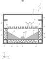
- Fig. 1 is a schematic cross-sectional side view of the deposition device 1 according to the present embodiment.
- each schematic cross-sectional side view of the deposition device according to the present disclosure shows a cross section passing through a plurality of openings 45 described later and along the normal direction of the inner surface of the bottom 41, and members located on the back side of the cross section as viewed from the paper surface are omitted.
- members formed as an integral unit are marked with the same hatching.
- the deposition apparatus 1 includes a vacuum chamber 10, a crucible 20, and a heater unit 30.
- the crucible 20 includes an outer shell 40 having an opening 45 for releasing the deposition material toward the deposition target, and an inner shell 50 that contacts at least a portion of the inner surface of the outer shell 40 and has a higher specific heat than the outer shell 40.
- the deposition apparatus 1 reduces changes in the deposition rate of the deposition film.
- the deposition apparatus 1, including the above, will be described in detail below.
- Vacuum chamber 10 has a housing 11, a target holder 12, and a crucible holder 13. Housing 11 is hollow and has an airtight interior. Target holder 12 and crucible holder 13 may protrude from the inner surface of housing 11, for example, or may be integral with housing 11.
- the housing 11 may have an entrance through which the deposition target on which the deposition film is formed by the deposition device 1 can be inserted and removed, and a door section that can close and seal the entrance.
- the target holder 12 may be capable of holding a deposition target that is introduced from outside the housing 11 through the entrance.
- the vacuum chamber 10 can create a vacuum inside the housing 11 with a pump (not shown).
- the shape of the housing 11 may be cylindrical from the viewpoint of maintaining strength when the inside is made vacuum, but is not limited to this and may also be rectangular.
- the crucible 20 described below is placed on the crucible holder 13, which holds the crucible 20 inside the housing 11.
- the crucible holder 13 may hold the crucible 20 inside the housing 11 with a distance between the inner surface of the housing 11 and the crucible 20.
- crucible> When a deposition material described later is placed in the crucible 20, the inside of the crucible 20 is heated by the heater unit 30, and the crucible 20 releases the deposition material toward the deposition target held by the target holder 12.
- the crucible 20 includes an outer shell 40 and an inner shell 50.
- Fig. 3A is a schematic plan view of the crucible 20
- Fig. 3B is a schematic cross-sectional view of the crucible 20.
- Fig. 3A is a schematic plan view of the crucible 20 when viewed in the direction A shown in Fig. 1, in other words, when the crucible 20 is viewed in a plan view from above to below.
- Fig. 3B is a cross-sectional view of the crucible 20 taken along the line B-B shown in Fig. 1, in other words, a schematic cross-sectional view of the crucible 20 showing a horizontal cross section of the inner surface of the bottom 41 of the outer shell 40, which will be described later, and which passes through the opening 45 side of the inner shell 50.
- each crucible according to this embodiment also show components located further back on the paper than the cross-section in order to show each part of the crucible in more detail. Also, all of the schematic cross-sectional views of each crucible according to this embodiment show a cross-section of the crucible that corresponds to the cross-section of crucible 20 shown in FIG. 3B.
- the outer shell 40 includes a bottom 41, a side 42, a top plate 43, a top plate protrusion 44, and an opening 45.
- the outer shell 40 has an internal space, for example a substantially rectangular shape, formed by the bottom 41, the side 42, and the top plate 43.
- the bottom 41 and the top plate 43 may be rectangular plate-like members facing each other.
- the side 42 is a side portion relative to the bottom 41, and in particular protrudes from the outer edge of the bottom 41 of the outer shell 40 towards the top plate 43 and connects to the outer edge of the top plate 43.
- the top plate protrusions 44 are formed on the outer surface of the top plate 43, in other words, they protrude toward the outside of the crucible 20.
- the openings 45 are formed on the inside of the top plate protrusions 44, and communicate the inside and outside of the outer shell 40. Therefore, the openings 45 are located between the bottom 41 and the position of the vapor deposition target placed on the target holder 12, in other words, the bottom 41 is located on the opposite side to the openings 45. Therefore, when the vapor deposition material is introduced into the crucible 20 and the inside of the crucible 20 is heated, the openings 45 release the vapor deposition material toward the vapor deposition target held by the target holder 12.
- the inner shell 50 is located inside the outer shell 40, and in particular, is in contact with at least a portion of the inner surface of the outer shell 40.
- the crucible 20 has a double structure of the outer shell 40 and the inner shell 50, which improves its strength.
- the inner shell 50 according to this embodiment has a higher specific heat than the outer shell 40.
- the outer shell 40 may contain a metal from the viewpoint of improving the strength of the crucible 20, and the inner shell 50 may contain a ceramic having a relatively higher specific heat than a metal.
- the temperature of the inner shell 50 increases more slowly than that of the outer shell 40 because the specific heat of the inner shell 50 is higher than that of the outer shell 40. Therefore, by including the outer shell 40 and the inner shell 50, the temperature of the entire inner surface of the crucible 20 in contact with the deposition material increases more slowly than when the crucible 20 only has the outer shell 40.
- the vapor deposition device 1 heats the vapor deposition material inside the crucible 20 more uniformly.
- the vapor deposition device 1 reduces differences in the consumption rate of the vapor deposition material depending on the position inside the crucible 20.
- the inner shell 50 experiences a smaller increase in temperature when the same amount of heat is applied, and a smaller drop in temperature when the same amount of heat is removed. Therefore, the inner surface of the crucible 20 is less susceptible to temperature fluctuations compared to the outer surface of the crucible 20. Therefore, the deposition apparatus 1 can more easily maintain a constant temperature inside the crucible 20.
- the deposition apparatus 1 reduces the difference in the amount of remaining deposition material depending on the position inside the crucible 20, and reduces the difference in the amount of deposition material consumed depending on the position inside the crucible 20.
- the deposition apparatus 1 also reduces the temperature change inside the crucible 20 over time, and reduces the change over time in the consumption rate of the deposition material inside the crucible 20. Therefore, the deposition apparatus 1 can make the consumption rate of the deposition material inside the crucible 20 more uniform regardless of the position inside the crucible 20 or the implementation time of the deposition film process, and thus makes the deposition rate of the deposition film more stable.
- a method of more uniformly heating the deposition material inside the crucible 20 is to mix a heat isolating material with high thermal conductivity.
- deposition materials are generally solid at room temperature, and the deposition material remaining inside the crucible 20 after the deposition process is completed hardens. For this reason, if a heat isolating material is mixed with the deposition material inside the crucible 20, it becomes difficult to separate the deposition material and the heat isolating material inside the crucible 20, which in turn makes it difficult to reuse the deposition material.
- mixing the deposition material with the heat isolating material may result in a longer heating time due to an increase in the specific heat of the deposition material, or the deposition material may be contaminated by the heat isolating material. As described above, mixing a heat isolating material with the deposition material makes it more difficult to handle the deposition material.
- the deposition device 1 includes a crucible 20 that has an outer shell 40 and an inner shell 50 that has a higher specific heat than the outer shell 40, thereby enabling more uniform heating of the deposition material inside. Therefore, the deposition device 1 does not require the above-mentioned heat equalizer in order to heat the deposition material inside the crucible 20 more uniformly. Therefore, the deposition device 1 can heat the deposition material inside the crucible 20 more uniformly while making it easier to handle the deposition material.
- the inner shell 50 has a higher heat capacity than the outer shell 40. This allows the deposition device 1 to further reduce localized heating of the inner surface of the crucible 20.
- the inner shell 50 contacts at least a portion of the side portion 42. This allows the deposition apparatus 1 to reduce localized heating of the inner surface of the inner shell 50 when the crucible 20 is heated from the side.
- the inner shell 50 contacts at least a portion of the bottom 41 and the side of the side portion 42 of the bottom 41. In this case, direct contact of the deposition material inside the crucible 20 with the inner surface of the portion of the inner shell 50 that is not in contact with the outer shell 40 or with the inner surface of the outer shell 40 is reduced. Therefore, with the above configuration, the deposition device 1 reduces localized heating of the deposition material regardless of a reduction in the deposition material inside the crucible 20.
- the inner shell 50 contacts the entire surface of the bottom 41 and the sides of the bottom 41 of each side 42.
- the deposition device 1 reduces localized heating of the deposition material on both the sides and below the crucible 20, regardless of a reduction in the deposition material inside the crucible 20.
- the inner shell 50 may have a rectangular bottom and sides protruding from each of multiple sides that define the outer edge of the bottom.
- the display portion of a display device is often rectangular. Therefore, by having the bottoms of the outer shell 40 and inner shell 50 be rectangular, the uniformity of the film thickness or quality of the evaporated film formed on the rectangular display portion of the display device 100 can be improved compared to other shapes such as a circle.
- the outer shell 40 and the inner shell 50 according to this embodiment are not particularly limited, so long as the inner shell 50 is in contact with at least a portion of the inner surface of the outer shell 40 and the specific heat of the inner shell 50 is higher than the specific heat of the outer shell 40.
- the inner shell 50 may be in contact with at least one of the bottom 41 and the side 42.
- the inner shell 50 may be in contact with the inner surface of the side 42 along the longitudinal direction of the bottom 41.
- the inner shell 50 of this embodiment is removably attached to the outer shell 40. Therefore, the deposition device 1 of this embodiment makes it easier to clean the inner surface of the crucible 20 or change the deposition material for the following reasons.
- deposition material may remain on the inner surface of the crucible of the deposition device even after the deposition film formation process, and periodic maintenance is required, including removing the deposition material and cleaning the inner surface of the crucible. Furthermore, when changing the material of the deposition film, replacing all of the deposition material inside the crucible can cause deposition material containing a different material to be mixed into the deposition material inside the crucible.
- the inner surface of the inner shell 50 can be more easily cleaned by removing the inner shell 50 from the outer shell 40 and cleaning the inner shell 50 outside the vacuum chamber 10. Also, by attaching a new inner shell 50 to the outer shell 40 while cleaning the inner shell 50, the deposition device 1 can continue to form a deposition film during the above cleaning.
- the vapor deposition device 1 can more easily change the material of the vapor deposition material inside the crucible 20.
- the heater unit 30 is disposed inside the housing 11, and heats the crucible 20 from the outside, thereby heating the crucible 20.
- the heater unit 30 includes a bottom heater 31 and a side heater 32 as heaters.
- the bottom heater 31 is disposed between the housing 11 and the bottom 41
- the side heater 32 is disposed between the housing 11 and the side 42.
- each heater included in the heater section 30 is disposed in a position facing the inner shell 50 via the outer shell 40.
- heat from the heater section 30 is efficiently transmitted to the inner shell 50 via the outer shell 40. Therefore, the deposition device 1 can heat the inner shell 50 more efficiently using the heater section 30. Therefore, in addition to the above configuration, considering that the specific heat of the inner shell 50 is higher than the specific heat of the outer shell 40, the deposition device 1 can efficiently heat the inside of the crucible 20 while reducing localized heating inside the crucible 20.
- the deposition apparatus 1 includes a single crucible 20, but is not limited thereto.
- the deposition apparatus 1 may include a plurality of crucibles 20 in which the deposition materials stored therein contain different materials.
- the deposition apparatus 1 may include a control unit (not shown) that controls the operation of each unit.
- the control unit may control evacuation of the inside of the vacuum chamber 10 and heating of the inside of the crucible 20 through control of the heater unit 30.
- Fig. 4 is a schematic side cross-sectional view of the deposition apparatus 1 in a deposition process.
- Fig. 4 also illustrates a deposition target X (to be described later) on whose surface a deposition film is formed by the deposition apparatus 1, and a deposition material M (material of the deposition film) stored inside a crucible 20.
- the manufacturing method of the display device 100 includes the step of sequentially depositing each layer of the light-emitting element 102 on the substrate 101, and at least one of the layers of the light-emitting element 102 is deposited using the deposition apparatus 1.
- the functional layers of the light-emitting element 102 including the hole injection layer 104, the hole transport layer 105, the light-emitting layer 106, and the electron transport layer 107, contain an organic material
- the functional layers may be formed by a deposition method in order to reduce deterioration of the functional layers.
- the new layer when a new layer is formed on the layer containing the organic material after it has been deposited, the new layer may be formed by a deposition method in order to reduce deterioration of the layer that has already been formed.
- a laminate including the substrate 101, in which the layers on the substrate 101 side from the layer to be formed are formed is placed inside the vacuum chamber 10 as the deposition target X.
- the laminate is placed on the target holder 12 with the surface on which the deposition film is to be formed facing downward, in other words, toward the crucible 20.
- the deposition apparatus 1 evacuates the inside of the vacuum chamber 10, creating a vacuum inside the vacuum chamber 10.
- the deposition material M may include, for example, a deposition material having sublimation properties, or may include a deposition material having melting properties.
- the deposition apparatus 1 heats the crucible 20, in which the material of the layer to be formed is stored as the deposition material M, to vaporize the deposition material M.
- the vaporized deposition material M inside the crucible 20 is released from the opening 45 of the outer shell 40 toward the laminate, which is the deposition target X.
- vaporization refers to a phase transition in which a liquid becomes a gas, or a phase transition in which a solid sublimes into a gas.
- the deposition apparatus 1 may heat the deposition material M inside the crucible 20 to change the deposition material M from a solid to a gas via a liquid, or may sublimate the deposition material M from a solid to a gas.
- the deposition material M released from the opening 45 reaches the surface of the laminate. Upon reaching the surface of the laminate, the deposition material M is cooled by contact with the surface of the laminate and becomes solid again. As a result, a deposition film containing the deposition material M is formed on the surface of the laminate facing the crucible 20.
- the layers of the light-emitting element 102 for example at least one of the anode 103 and the cathode 108, and the light-emitting layer 106 may be formed in an island shape for each subpixel on the substrate 101.
- deposition of each layer may be performed through a deposition mask, such as a metal mask, that is arranged on the crucible 20 side of the laminate and has openings at positions corresponding to each subpixel.
- a layer containing multiple materials may be formed by co-deposition in which multiple crucibles 20 are heated simultaneously to form a film.
- At least one of the layers of the light-emitting element 102 may be formed by a vapor deposition method using the vapor deposition apparatus 1.
- some of the layers of the light-emitting element 102 may be formed by a method other than the vapor deposition method, such as a sputtering method, a photolithography method, or an inkjet method.
- the deposition material M inside the crucible 20 is always in contact with the inner wall 50 regardless of the decrease in the deposition material M. Therefore, the deposition device 1 can more uniformly heat the deposition material M in contact with the inner wall 50, which has a higher specific heat than the outer wall 40. Therefore, the manufacturing method of the display device 100 makes the deposition rate of the deposition film more uniform, improves the quality of the deposition film, and improves the characteristics, life, etc. of the light-emitting element 102.
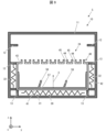
- FIG. 5 is a schematic cross-sectional view of a deposition apparatus 2 according to this embodiment.
- the deposition apparatus 2 differs in configuration from the deposition apparatus 1 according to the previous embodiment only in that it includes a crucible 21 instead of the crucible 20.
- the crucible 21 differs in configuration from the crucible 20 only in that it includes an inner shell 51 instead of the inner shell 50.
- the inner shell 51 has a tapered portion 52 whose thickness decreases from the end side of the bottom 41 toward the center. Except for the above points, the inner shell 51 has the same configuration as the inner shell 50.
- the inner shell 51 is in contact with at least a portion of the inner surface of the outer shell 40, and has a higher specific heat than the specific heat of the outer shell 40. Therefore, the deposition device 2 according to this embodiment can further reduce localized heating of the inner surface of the crucible 21, and more stabilize the deposition rate of the deposition film.
- the inner shell 51 of the crucible 21 has a tapered portion 52
- the vapor deposition material inside the crucible 21 is concentrated at the center of the crucible 21. Therefore, even when the amount of vapor deposition material inside the crucible 21 is small, the vapor deposition device 2 heats the vapor deposition material more uniformly, making the deposition rate of the vapor deposition film more stable. Furthermore, the vapor deposition material inside the crucible 20 is separated from the side portion 42 of the crucible 20 by the tapered portion 52. Therefore, even when the heating of the side portion 42 of the crucible 21 is insufficient, the vapor deposition device 2 reduces adhesion of the vapor deposition material to the side portion 42 of the inner surface of the crucible 21.
- FIG. 6 is a schematic cross-sectional view of a deposition apparatus 3 according to this embodiment.
- the deposition apparatus 3 differs in configuration from the deposition apparatus 2 according to the previous embodiment only in that it includes a crucible 22 instead of the crucible 21.
- the crucible 22 differs in configuration from the crucible 21 only in that it includes an inner shell 53 instead of the inner shell 51.
- the inner shell 53 has the tapered portion 52 described above, and a protruding portion 54 that protrudes toward the opening 45 at a position closer to the center than the tapered portion 52. Except for the above, the inner shell 53 has the same configuration as the inner shell 51. For example, the inner shell 53 is in contact with at least a portion of the inner surface of the outer shell 40, and has a higher specific heat than the specific heat of the outer shell 40. Therefore, the deposition device 3 according to this embodiment can further reduce localized heating of the inner surface of the crucible 22, and more stabilize the deposition rate of the deposition film.
- the deposition material inside the crucible 22 is concentrated on the side of the protruding portion 54.
- the protruding portion 54 is thicker than the surrounding area, even if the deposition material is concentrated around the protruding portion 54, the protruding portion 54 reduces the increase in the thickness of the deposition material, thereby reducing insufficient heating of the deposition material. Therefore, the deposition device 3 heats the deposition material more uniformly even if the deposition material is concentrated on the center side of the crucible 22, making the deposition rate of the deposition film more stable.
- FIG. 7 is a schematic cross-sectional view of a vapor deposition apparatus 4 according to this embodiment.
- the vapor deposition apparatus 4 differs in configuration from the vapor deposition apparatus 1 according to the above-described embodiment 1 only in that it includes a crucible 23 instead of the crucible 20.
- the crucible 23 differs in configuration from the crucible 20 only in that it includes an inner shell 55 instead of the inner shell 50.
- the inner shell 55 has at least one partition wall 56 that protrudes into the inside of the crucible 23. Therefore, a portion of the internal space of the crucible 23 on the side of the bottom 41 is divided into multiple spaces by the partition wall 56. As a result, a portion of the deposition material introduced into the inside of the crucible 23 on the side of the bottom 41 is divided by the partition wall 56. Except for the above points, the inner shell 55 has the same configuration as the inner shell 50. For example, the inner shell 55 is in contact with at least a portion of the inner surface of the outer shell 40, and has a specific heat higher than that of the outer shell 40.
- the crucible 23 When the crucible 23 is heated by the heater section 30, the heat propagated to the inner wall 55 also propagates to the partition wall 56. Therefore, the crucible 23 can heat the deposition material located on the central side, which is farther away from each heater section 30, particularly each side heater 32, through the partition wall 56. Therefore, the deposition device 4 can heat the deposition material more uniformly regardless of the position inside the crucible 23.
- the partition 56 in this embodiment protrudes in approximately the same direction as the normal direction C of the inner surface of the bottom 41. Therefore, no space is formed in the crucible 23 below the partition 56. Therefore, the deposition device 4 reduces the vaporized deposition material coming into contact with the partition 56 and solidifying, and increases the deposition material that reaches the deposition target. Note that in this embodiment, "approximately the same direction” does not mean that the two are completely the same, but allows for some deviation in the direction of the two, including manufacturing errors, etc.
- the inner shell 55 has multiple partition walls 56. This allows the deposition device 4 to more efficiently heat the deposition material located toward the center of the crucible 23 through the multiple partition walls 56. Therefore, the deposition device 4 can heat the deposition material more uniformly regardless of the position inside the crucible 23.
- FIG. 8 is a schematic cross-sectional view of the crucible 23 according to this embodiment.
- the partition 56 When viewed in the normal direction to the inner surface of the bottom 41, as shown in FIG. 8, the partition 56 extends parallel to one of the multiple sides that define the outer edge of the bottom 41. In particular, the partition 56 extends parallel to the short direction of the outer edge of the bottom 41. Note that in this embodiment, "parallel" does not mean that the two are completely aligned in the same direction, but rather allows for misalignment of the directions of the two, including manufacturing errors, etc.
- the deposition device 4 can reduce the difference in the heating conditions of the deposition material between the multiple regions, and can heat the deposition material more uniformly.
- the partition 56 is located between the first and second sides of the multiple sides that define the outer edge of the bottom 41.
- the partition 56 is located between two sides of the outer edge of the bottom 41 that face each other and run along the longitudinal direction.
- the deposition device 4 can heat each of the partitioned deposition materials more uniformly by reducing the heat capacity of each of the partitioned deposition materials.
- the uniform heating of the deposition material in each of the above spaces of the crucible 23 in this embodiment becomes noticeable when the deposition material inside the crucible 23 is consumed and the upper surface of the deposition material falls below the upper end of the partitions 56.
- FIG. 9 is a schematic cross-sectional view of a deposition apparatus 5 according to this embodiment.
- the deposition apparatus 5 differs in configuration from the deposition apparatus 4 according to the previous embodiment only in that it includes a crucible 24 instead of the crucible 23.
- the crucible 24 differs in configuration from the crucible 23 only in that it includes an inner shell 57 instead of the inner shell 55.
- the inner shell 57 of this embodiment has at least one partition wall 58 that protrudes inwardly into the crucible 24.
- the partition wall 58 of this embodiment protrudes in a direction different from the normal direction C of the inner surface of the bottom 41.
- the inner shell 57 has the same configuration as the inner shell 55.
- the inner shell 57 is at least partially in contact with the inner surface of the outer shell 40, and has a specific heat higher than that of the outer shell 40.
- the position of the crucible is fixed relative to the vacuum chamber, but this is not limited to the above.
- the deposition apparatus including each of the deposition devices described above may heat the deposition material while changing the position of the crucible relative to the deposition target to form a deposition film on the deposition target.
- the deposition material including the material of the deposition film is a meltable material
- the deposition material may flow inside the crucible as the crucible moves. The flow of the deposition material inside the crucible leads to a decrease in the uniformity of heating of the deposition material.
- the partition 58 in this embodiment protrudes in a direction different from the normal direction C of the inner surface of the bottom 41, so even if the deposition material, which is a fusible material, flows horizontally and collides with the partition 58, the turbulence caused by the collision is mitigated by the partition 58. As a result, the partition 58 more restricts the flow of the deposition material inside the inner shell 57 in response to the movement of the crucible 24 than the partition 56 described above. Therefore, the deposition device 5 in this embodiment can heat the deposition material more uniformly regardless of the movement of the crucible 24.
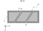
- FIGs. 10A and 10B are schematic cross-sectional views of the crucible 24 according to this embodiment.
- Fig. 10A shows a schematic cross-sectional view of crucible 24A, which is an example of the crucible 24 according to this embodiment
- Fig. 10B shows a schematic cross-sectional view of crucible 24B, which is another example of the crucible 24.
- crucible 24A has partition 58A as partition 58.
- partition 58A extends along a direction intersecting with any of the sides of bottom 41 among the multiple sides that define the outer edge of bottom 41 when viewed in the normal direction to the inner surface of bottom 41. Therefore, even if the deposition material, which is a meltable material, flows horizontally and collides with partition 58A, the turbulence caused by the collision is mitigated by partition 58A. Therefore, even in deposition device 5 equipped with crucible 24A, the deposition material can be heated more uniformly regardless of the movement of crucible 24A.
- the partitions 58A are located between two opposing longitudinal sides of the outer edge of the bottom 41. As a result, a portion of the vapor deposition material inside the crucible 24A on the side of the bottom 41 is divided into multiple sections by the partitions 58A.
- the vapor deposition device 5 equipped with the crucible 24A can therefore heat each of the vapor deposition materials more uniformly by reducing the heat capacity of each of the divided vapor deposition materials.
- crucible 24B has partition 58B as partition 58.
- partition 58B extends along a direction intersecting with any of the sides of bottom 41 among the multiple sides that define the outer edge of bottom 41 when viewed in the normal direction of the inner surface of bottom 41. Therefore, even in deposition device 5 equipped with crucible 24B, the deposition material can be heated more uniformly regardless of the movement of crucible 24B.
- the partition 58B is located on a portion of the outer edge of the bottom 41 from the first side to the second side. Therefore, a portion of the internal space of the crucible 24B on the side of the bottom 41 is not partitioned by the partition 58B and becomes a single space. Therefore, the deposition device 5 equipped with the crucible 24B causes the deposition material to flow inside the crucible 24B, and heat is propagated between distant positions of the crucible 24B, thereby heating the deposition material more uniformly.
- FIG. 11 is a schematic cross-sectional view of a deposition apparatus 6 according to this embodiment.
- the deposition apparatus 6 differs in configuration from the deposition apparatus 5 according to the previous embodiment only in that it includes a crucible 25 instead of the crucible 24.
- the crucible 25 differs in configuration from the crucible 24 only in that it includes an inner shell 59 instead of the inner shell 57.
- the inner shell 59 according to this embodiment has at least one partition 60 that protrudes into the inside of the crucible 25.
- the partition 60 according to this embodiment protrudes in a direction different from the normal direction C of the inner surface of the bottom 41.
- any one of the multiple partitions 60 protrudes in a direction different from the protruding direction of any other partition 60.
- the inner shell 59 has the same configuration as the inner shell 57.
- the inner shell 59 is at least partially in contact with the inner surface of the outer shell 40, and has a specific heat higher than that of the outer shell 40.
- the multiple partitions 60 in this embodiment protrude in different directions, when the vapor deposition material, which is a fusible material, flows horizontally and collides with a partition 60, the direction of flow changes depending on the partition 60 that collides.
- the partition 60 further reduces turbulence of the vapor deposition material inside the inner shell 59 in response to the movement of the crucible 25, and further restricts the flow of the vapor deposition material. Therefore, the vapor deposition device 6 in this embodiment can heat the vapor deposition material more uniformly regardless of the movement of the crucible 25.
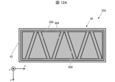
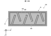
- FIGS. 12A and 12B are schematic cross-sectional views of the crucible 25 according to this embodiment.
- FIG. 12A shows a schematic cross-sectional view of crucible 25A, which is an example of the crucible 25 according to this embodiment
- FIG. 12B shows a schematic cross-sectional view of crucible 25B, which is another example of the crucible 25.
- the crucible 25A has a partition 60A as the partition 60.
- any one of the multiple partitions 60A extends in a direction different from the extension direction of any other partition 60A.
- the deposition device 6 including the crucible 25A further reduces turbulence of the deposition material inside the inner shell 59 in response to the movement of the crucible 25A, and heats the deposition material more uniformly regardless of the movement of the crucible 25A.
- the partitions 60A are located between two opposing longitudinal sides of the outer edge of the bottom 41. As a result, a portion of the vapor deposition material inside the crucible 25A on the side of the bottom 41 is divided into multiple sections by the partitions 60A.
- the vapor deposition device 6 equipped with the crucible 25A can therefore heat each of the vapor deposition materials more uniformly by reducing the heat capacity of each of the divided vapor deposition materials.
- crucible 25B has partition 60B as partition 60.
- any one of the multiple partitions 60B extends in a direction different from the extension direction of any other partition 60B. Therefore, deposition device 6 equipped with crucible 25B heats the deposition material more uniformly regardless of the movement of crucible 25B.
- the partition 60B is located on a portion of the outer edge of the bottom 41 from the first side to the second side. Therefore, the vapor deposition material inside the crucible 25B is not divided by the partition 60B but is integrated. Therefore, the vapor deposition device 5 equipped with the crucible 25B causes the vapor deposition material to flow inside the crucible 25B, and heat is propagated between distant positions of the crucible 25B, thereby heating the vapor deposition material more uniformly.
- the inner shell of the deposition device according to each of the above-mentioned embodiments is detachably attached to the outer shell 40. Therefore, the deposition device according to each embodiment can easily change the inner shell attached to the outer shell 40 depending on the material to be deposited or the deposition target. For example, the deposition device according to each embodiment can easily change the presence or absence or shape of the above-mentioned tapered portion, protrusion, or partition in the inner shell by changing the inner shell attached to the outer shell. Therefore, the deposition device according to each embodiment makes it easy to form a deposition film using a crucible that is more suitable for the material of the deposition material and the deposition target.
- Vapor deposition apparatus 10
- Crucible 31
- Bottom heater (heater) 32
- Side heater (heater) 40
- Outer shell 41
- Bottom portion 42
- Side portion 45
- Opening portion 50
- Inner shell 52
- Tapered portion 54
- Protruding portion 56
- Partition wall 100
- Display device 102 Light-emitting element
Landscapes
- Chemical & Material Sciences (AREA)
- Chemical Kinetics & Catalysis (AREA)
- Engineering & Computer Science (AREA)
- Materials Engineering (AREA)
- Mechanical Engineering (AREA)
- Metallurgy (AREA)
- Organic Chemistry (AREA)
- Physical Vapour Deposition (AREA)
Abstract
蒸着装置は坩堝を備え、坩堝は外殻と内殻とを含む。外殻は、蒸着材を蒸着対象に向けて放出する開口部を有する。内殻は、外殻の内面の少なくとも一部と接し、かつ、外殻よりも比熱が高い。
Description
本開示は、蒸着膜を形成するための蒸着装置および当該蒸着装置を用いた表示装置の製造方法に関する。
薄膜の形成法として、坩堝中の材料をヒータにて溶融および蒸発させて、坩堝の上方に位置する物体の表面に接触させて凝固させることにより、当該材料を含む薄膜を物体の表面に形成する蒸着法が知られている。また、OLED等の発光素子を備えた表示装置の製造方法において、発光素子の各層の劣化を低減するために、当該各層の形成に蒸着装置を用いた蒸着法が採用される場合がある。特許文献1には、蒸着装置を用いた蒸着工程において有機EL素子の有機層を成膜する方法が開示される。
特許文献1に記載されるような蒸着工程においては、坩堝内部における加熱ムラ、坩堝内に残存する蒸着材の偏り等に起因して、蒸着膜の成膜レートの変化が生じる場合がある。蒸着工程における蒸着膜の成膜レートの変化は、蒸着膜の品質低下、あるいは、成膜レートを安定させるための工程の実行に伴うタクトタイムの延長またはコストの増大につながる。
本開示の一態様に係る蒸着装置は、蒸着材を蒸着対象に向けて放出する開口部を有する外殻と、前記外殻の内面の少なくとも一部と接し、かつ、前記外殻よりも比熱が高い内殻と、を含む坩堝を備える。
蒸着装置による蒸着膜の成膜レートの変化を低減する。
〔実施形態1〕
<表示装置>
以下、本開示の実施形態について図面を参照しつつ説明する。なお、各図面において、同様の構成については同一の符号を付してその説明を省略する。
<表示装置>
以下、本開示の実施形態について図面を参照しつつ説明する。なお、各図面において、同様の構成については同一の符号を付してその説明を省略する。
本実施形態に係る表示装置について、図2を参照して説明する。図2は本実施形態に係る表示装置100の概略側断面図である。表示装置100は、例えば、テレビまたはスマートフォン等のディスプレイに用いることのできる装置である。表示装置100は、例えばTFT基板である基板101と、基板101上に複数形成された発光素子102と、を備える。
発光素子102は、例えば、基板101の側から順に、第1電極であるアノード103、正孔注入層104、正孔輸送層105、発光層106、電子輸送層107、および第2電極であるカソード108を有する。なお、発光素子102の構造は上記構成に限られず、基板101の側から順に、カソード108、電子輸送層107、発光層106、正孔輸送層105、正孔注入層104、およびアノード103を有してもよい。また、発光素子102は、アノード103とカソード108との間に、少なくとも発光層106を有する限り、正孔注入層104、正孔輸送層105、および、電子輸送層107のうち少なくとも一層を備えていなくともよい。換言すれば、発光素子102は、アノード103とカソード108との間に、少なくとも発光層106を含む機能層を有する。また、発光素子102は、例えば電子輸送層107とカソード108との間の電子注入層を含む、さらなる機能層を有してもよい。
表示装置100は、基板101に形成された不図示のドライバ等を介して各発光素子102のアノード103とカソード108との間に電圧を印加する。電圧を印加された各発光素子102は、アノード103から正孔注入層104および正孔輸送層105を介して発光層106に正孔を注入し、また、カソード108から電子輸送層107を介して発光層106に電子を注入する。発光層106は、例えば有機発光材料を含む発光材料を有し、注入された正孔と電子との再結合により生じた励起子によって発光する。アノード103およびカソード108の少なくとも一方は光透過性である透過電極であり、発光素子102は発光層106から生じた光を透過電極の側に取り出す。これにより、表示装置100は各発光素子102から個々に光を取り出すことにより表示を行う。
本実施形態に係る表示装置100の製造方法としては、例えば、基板101上に発光素子102の各層を順に成膜する方法が挙げられる。ここで、特に本実施形態に係る表示装置100の製造方法においては、発光素子102の各層のうち少なくとも一層は、後述する蒸着装置を用いた蒸着法により成膜される。
<蒸着装置:概要>
本実施形態に係る蒸着装置について図1を参照して説明する。図1は本実施形態に係る蒸着装置1の概略側断面図である。なお、図1を含む本開示の各蒸着装置の概略側断面図は、何れも後述する複数の開口部45を通り、底部41の内面の法線方向に沿う断面について示し、また、当該断面よりも紙面向かって奥側に位置する部材の図示を省略する。また、図1を含む本開示の各図において、一体として形成されている部材には同一のハッチングを付す。
本実施形態に係る蒸着装置について図1を参照して説明する。図1は本実施形態に係る蒸着装置1の概略側断面図である。なお、図1を含む本開示の各蒸着装置の概略側断面図は、何れも後述する複数の開口部45を通り、底部41の内面の法線方向に沿う断面について示し、また、当該断面よりも紙面向かって奥側に位置する部材の図示を省略する。また、図1を含む本開示の各図において、一体として形成されている部材には同一のハッチングを付す。
蒸着装置1は、真空チャンバ10と、坩堝20と、ヒータ部30と、を備える。坩堝20は、後述するように、蒸着材を蒸着対象に向けて放出する開口部45を有する外殻40と、外殻40の内面の少なくとも一部と接し、かつ、外殻40よりも比熱が高い内殻50と、を含む。上記構成により、本実施形態に係る蒸着装置1は、蒸着膜の成膜レートの変化を低減する。以下、上記を含め蒸着装置1について詳細に説明する。
<蒸着装置:真空チャンバ>
真空チャンバ10は、筐体11と、対象保持部12と、坩堝保持部13と、を有する。筐体11は中空であり、内部を気密する。対象保持部12および坩堝保持部13は、例えば筐体11の内面から突出してもよく、換言すれば筐体11と一体であってもよい。
真空チャンバ10は、筐体11と、対象保持部12と、坩堝保持部13と、を有する。筐体11は中空であり、内部を気密する。対象保持部12および坩堝保持部13は、例えば筐体11の内面から突出してもよく、換言すれば筐体11と一体であってもよい。
筐体11は蒸着装置1により蒸着膜が形成される蒸着対象を出し入れ可能な出入口と、当該出入口を開閉可能に密閉する扉部と、を備えていてもよい。対象保持部12には、筐体11の外部から出入口を介して投入された蒸着対象を載置可能であってもよい。真空チャンバ10は、対象保持部12に蒸着対象Xを載置し、かつ、扉部により出入口を密閉した状態において、不図示のポンプにより筐体11の内部を真空とすることができる。筐体11の形状は、内部を真空とした場合における強度維持等の観点から、円筒形状を有してもよいが、これに限られず、直方形状を有してもよい。
坩堝保持部13は、後述する坩堝20が載置されることにより筐体11の内部において坩堝20を保持する。例えば、坩堝保持部13は、筐体11の内面と坩堝20との距離をおいて、筐体11の内部に坩堝20を保持してもよい。
<蒸着装置:坩堝>
坩堝20は、後述する蒸着材が投入された状態において内部をヒータ部30によって加熱されることにより、蒸着材を対象保持部12に保持された蒸着対象に向けて放出する。坩堝20は、外殻40と、内殻50と、を含む。
坩堝20は、後述する蒸着材が投入された状態において内部をヒータ部30によって加熱されることにより、蒸着材を対象保持部12に保持された蒸着対象に向けて放出する。坩堝20は、外殻40と、内殻50と、を含む。
図1と併せて図3Aおよび図3Bを参照し、坩堝20についてより詳細に説明する。図3Aは坩堝20の概略平面図であり、図3Bは坩堝20の概略断面図である。図3Aは図1に示す方向A、換言すれば、坩堝20の上方から下方に向かって坩堝20を平面視した場合における坩堝20の概略平面図である。また、図3Bは坩堝20の図1に示すB-B矢視断面図であり、換言すれば、後述する外殻40の底部41の内面の水平、かつ、内殻50よりも開口部45の側を通る断面について示す坩堝20の概略断面図である。
なお、図3Bを含む本実施形態に係る各坩堝の概略断面図は、坩堝の各部をより詳細に示すために、断面よりも紙面に向かって奥に位置する部材を併せて示している。また、本実施形態に係る各坩堝の概略断面図は、何れも図3Bに示す坩堝20の断面と対応する坩堝の断面を示す。
外殻40は、底部41と、側部42と、天板部43と、天板突出部44と、開口部45と、を含む。外殻40は、底部41、側部42、および天板部43により形成される例えば略直方形状の空間を内部に有する。この場合、底部41と天板部43とは互いに対向する四角形状の板状部材であってもよい。側部42は底部41に対する側部であり、特に外殻40の底部41の外縁から天板部43に向かって突出し、天板部43の外縁と接続する。
天板突出部44は、天板部43の外面に複数形成され、換言すれば坩堝20の外側に向かって突出する。開口部45は天板突出部44の内側に形成され、外殻40の内外を連通する。このため、底部41と対象保持部12に載置された蒸着対象の位置との間に開口部45が位置し、換言すれば、底部41は開口部45の側と反対の側に位置する。したがって、開口部45は、坩堝20の内部に蒸着材が投入された状態において坩堝20の内部が加熱された際に、当該蒸着材を対象保持部12に保持された蒸着対象に向けて放出する。
内殻50は、外殻40の内側に位置し、特に、外殻40の内面の少なくとも一部と接する。坩堝20は外殻40と内殻50との二重構造を有していることにより強度を向上する。また、本実施形態に係る内殻50は、外殻40と比較して比熱が高い。例えば、外殻40は坩堝20の強度の向上等の観点から金属を含んでもよく、内殻50は金属よりも比較的比熱の高いセラミックスを含んでもよい。
後述するヒータ部30により坩堝20の内部が外殻40および内殻50を介して加熱された場合、外殻40の比熱より内殻50の比熱の方が高いことに起因して、外殻40の温度上昇と比較して内殻50の温度上昇はより緩やかに生じる。このため、坩堝20は、外殻40と内殻50とを含むことにより、外殻40のみを備える場合と比較して、蒸着材が接する坩堝20の内面全体の温度上昇がより緩やかに生じる。
したがって、蒸着装置1は、坩堝20の外部からの加熱により外殻40の温度にムラが生じた場合においても、外殻40の熱が内殻50に緩やかに伝搬するため、坩堝20の内部が局所的に加熱されることを低減する。ゆえに蒸着装置1は、坩堝20の内部の蒸着材をより均一に加熱する。坩堝20の内部の蒸着材を均一に加熱することにより、蒸着装置1は、坩堝20の内部の位置による、当該蒸着材の消費速度の差異を低減する。
また、内殻50は外殻40と比較して、同量の熱量が与えられた場合において温度の上昇が小さく、また、同量の熱量が奪われた場合において温度の降下が小さい。このため、坩堝20の内面は坩堝20の外面と比較して温度の上下が生じにくい。したがって、蒸着装置1は坩堝20の内部における温度をより一定に保持しやすい。
これにより、蒸着装置1は、坩堝20の内部の位置による残存する蒸着材の量の差異を低減し、坩堝20の内部の位置による蒸着材の消費量の差異を低減する。また、蒸着装置1は、経時的な坩堝20の内部の温度変化を低減し、坩堝20の内部の蒸着材の消費速度の経時変化を低減する。したがって、蒸着装置1は、坩堝20の内部の位置または蒸着膜の工程の実施時間等によらず、坩堝20の内部の蒸着材の消費速度をより均一とでき、ひいては蒸着膜の成膜レートをより安定させる。
例えば、坩堝20の内部の蒸着材をより均一に加熱する方法としては、蒸着材に熱伝導率の高い均熱材を混合させる方法が考えられる。しかしながら、一般に蒸着材は常温にて固体であり、蒸着工程の完了後に坩堝20の内部に残留した蒸着材は硬化する。このため、坩堝20の内部の蒸着材に均熱材を混合させた場合、坩堝20の内部に蒸着材と均熱材との分離が困難となり、ひいては蒸着材の再利用が困難となる。また、蒸着材と均熱材とを混合させることにより、蒸着材の比熱の上昇に伴う加熱時間の長時間化、あるいは、均熱材による蒸着材の汚染の可能性を招来する。以上の通り、均熱材を蒸着材に混合することは、蒸着材の取扱いをより困難とする。
本実施形態に係る蒸着装置1は、外殻40と当該外殻40よりも比熱の高い内殻50とを有することにより、内部の蒸着材の加熱をより均一とできる坩堝20を備える。このため、蒸着装置1は、坩堝20の内部の蒸着材をより均一に加熱するために、上述した均熱材を要しない。このため蒸着装置1は、蒸着材の取扱いをより容易としつつ、坩堝20の内部の蒸着材をより均一に加熱できる。
特に、本実施形態において、内殻50は外殻40よりも熱容量が高い。これにより蒸着装置1は、坩堝20の内面の局所的な加熱をより低減できる。
例えば内殻50は、側部42の少なくとも一部と接する。これにより蒸着装置1は、坩堝20が側方から加熱された場合における内殻50の内面の局所的な加熱を低減する。
また、内殻50は、底部41の少なくとも一部、および側部42の底部41の側と接する。この場合、坩堝20の内部の蒸着材が、外殻40と触れていない内殻50の部分の内面、あるいは、外殻40の内面に直接接触することを低減する。したがって、上記構成により蒸着装置1は、坩堝20の内部の蒸着材の減少に関わらず、蒸着材が局所的に加熱されることを低減する。
特に、本実施形態に係る内殻50は、底部41の全面、および各側部42の底部41の側と接する。上記構成により蒸着装置1は、坩堝20の内部の蒸着材の減少に関わらず、坩堝20の側方および下方の双方における蒸着材の局所的な加熱を低減する。この場合、内殻50は四角形状の底部と当該底部の外縁を規定する複数の辺のそれぞれから突出する側部とを有してもよい。
一般に、上述した表示装置100を含む表示装置の表示部は四角形状であることが多い。このため、外殻40および内殻50の底部が四角形状であることにより、円形状等他の形状である場合と比較して、表示装置100の四角形状の表示部に形成される蒸着膜の膜厚または品質等の均一性を向上できる。
ただし、本実施形態に係る外殻40および内殻50は、内殻50が外殻40の内面の少なくとも一部と接し、かつ、内殻50の比熱が外殻40の比熱よりも高い限り、特に限定されない。例えば、内殻50は底部41と側部42との少なくとも一方と接してもよい。例えば、内殻50は、坩堝20の強度を確保する観点から、底部41の長手方向に沿う側部42の内面と接してもよい。
本実施形態に係る内殻50は外殻40に着脱可能に取り付けられる。このため本実施形態に係る蒸着装置1は、以下の理由から、坩堝20の内面の清掃または蒸着材の変更が、より容易に実行できる。
一般に、蒸着装置の坩堝の内面には蒸着膜の形成工程後においても蒸着材が残存する場合があり、定期的に当該蒸着材を取り除く、坩堝の内面の清掃を含むメンテナンスが必要である。また、蒸着膜の材料を変更する場合、坩堝の内部の蒸着材を全て取り替える方法は、坩堝の内部の蒸着材への異なる材料を含む蒸着材の混入の原因となり得る。
例えば、内殻50を外殻40から取り外し真空チャンバ10の外部において内殻50の清掃を実行することにより、内殻50の内面はより容易に清掃できる。また、内殻50の清掃を実行する間、新たな内殻50を外殻40に取り付けることにより、上記清掃の間蒸着装置1による蒸着膜の形成を継続できる。
また、ある材料を含む蒸着材が格納された内殻50を外殻40から取り外した後、他の材料を含む蒸着材が格納された内殻50を外殻40に取り付けることにより、蒸着装置1はより容易に坩堝20の内部の蒸着材の材料を変更できる。また、上記方法によれば、互いに異なる材料を含む蒸着材同士が直接接することを防止できるため、坩堝20の内部の蒸着材への異なる材料を含む蒸着材の混入を低減できる。
<蒸着装置:ヒータ>
図1の参照に戻ると、ヒータ部30は筐体11の内部に配され、坩堝20を外部から加熱することにより坩堝20を加熱する。ヒータ部30の具体的な加熱機構等は特に問われない。本実施形態において、ヒータ部30はヒータとして底部ヒータ31と側部ヒータ32とを含む。底部ヒータ31は筐体11と底部41との間に配され、側部ヒータ32は筐体11と側部42との間に配される。
図1の参照に戻ると、ヒータ部30は筐体11の内部に配され、坩堝20を外部から加熱することにより坩堝20を加熱する。ヒータ部30の具体的な加熱機構等は特に問われない。本実施形態において、ヒータ部30はヒータとして底部ヒータ31と側部ヒータ32とを含む。底部ヒータ31は筐体11と底部41との間に配され、側部ヒータ32は筐体11と側部42との間に配される。
このため、ヒータ部30が含む各ヒータは外殻40を介して内殻50と対向する位置に配されている。この場合、ヒータ部30からの熱は外殻40を介して効率的に内殻50に伝搬する。したがって、蒸着装置1は、ヒータ部30によってより効率的に内殻50を加熱できる。ゆえに、上記構成と併せて、外殻40の比熱よりも内殻50の比熱が高いことを鑑みると、蒸着装置1は効率的に坩堝20の内部を加熱しつつ、坩堝20の内部の局所的な加熱を低減できる。
<蒸着装置:補記>
蒸着装置1は単一の坩堝20を備えているが、これに限られない。例えば、蒸着装置1は、内部に格納される蒸着材が含む材料が互いに異なる複数の坩堝20を備えてもよい。蒸着装置1は、各部の動作を制御する不図示の制御部を備えてもよい。制御部は、例えば、真空チャンバ10の内部の排気、およびヒータ部30の制御を介した坩堝20の内部の加熱を制御してもよい。
蒸着装置1は単一の坩堝20を備えているが、これに限られない。例えば、蒸着装置1は、内部に格納される蒸着材が含む材料が互いに異なる複数の坩堝20を備えてもよい。蒸着装置1は、各部の動作を制御する不図示の制御部を備えてもよい。制御部は、例えば、真空チャンバ10の内部の排気、およびヒータ部30の制御を介した坩堝20の内部の加熱を制御してもよい。
<表示装置の製造方法>
図4を参照し本実施形態に係る表示装置100の製造方法について説明する。図4は蒸着工程における蒸着装置1の概略側断面図である。図4は蒸着装置1によって表面に蒸着膜が形成される後述の蒸着対象X、および蒸着膜の材料であり坩堝20の内部に格納される蒸着材Mについても図示している。
図4を参照し本実施形態に係る表示装置100の製造方法について説明する。図4は蒸着工程における蒸着装置1の概略側断面図である。図4は蒸着装置1によって表面に蒸着膜が形成される後述の蒸着対象X、および蒸着膜の材料であり坩堝20の内部に格納される蒸着材Mについても図示している。
本実施形態に係る表示装置100の製造方法は、上述の通り、基板101上に発光素子102の各層を順に成膜する工程を含み、発光素子102の各層のうち少なくとも一層は蒸着装置1を用いて成膜される。
特に、発光素子102のうち、正孔注入層104、正孔輸送層105、発光層106、および電子輸送層107を含む機能層が有機材料を含む場合、当該機能層の劣化を低減する観点から、機能層は蒸着法によって成膜されてもよい。また、有機材料を含む層が蒸着された後、当該層上にさらに新たな層の成膜を行う場合にも、既に成膜された層の劣化を低減する観点から、新たな層は蒸着法によって成膜されてもよい。
蒸着装置1を用いた発光素子102の何れかの層の成膜工程においては、例えば、成膜する層より基板101の側の各層までが形成された、基板101を含む積層体を蒸着対象Xとして真空チャンバ10の内部に投入する。ここで積層体は蒸着膜が成膜される面を下側、換言すれば坩堝20の側に向けて対象保持部12上に載置される。次いで、蒸着装置1は、真空チャンバ10の内部の排気を行い、真空チャンバ10の内部を真空とする。
ここまでに、坩堝20の内部には成膜工程において成膜する層の材料が蒸着材Mとして内部に格納される。蒸着材Mは、例えば、昇華性を有する蒸着材を含んでもよく、あるいは、溶融性を有する蒸着材を含んでもよい。
次いで、蒸着装置1は、成膜する層の材料が蒸着材Mとして内部に格納された坩堝20を加熱し当該蒸着材Mを気化させる。これにより、坩堝20の内部において気化した蒸着材Mは外殻40の開口部45から蒸着対象Xである積層体に向かって放出される。なお、本明細書における『気化』とは、液体が気体となる相転移、または固体が気体に昇華する相転移を指す。換言すれば、蒸着装置1は、坩堝20の内部の蒸着材Mを加熱して、蒸着材Mを固体から液体を介して気体にしてもよく、あるいは蒸着材Mを固体から気体に昇華させてもよい。
開口部45から放出された蒸着材Mは積層体の表面に到達する。積層体の表面に到達した蒸着材Mは、積層体の表面との接触により冷却され再び固体となる。これにより、積層体の坩堝20の側の表面には、蒸着材Mを含む蒸着膜が成膜される。
発光素子102の各層のうち、例えばアノード103とカソード108との少なくとも一方、および発光層106は、基板101上のサブ画素ごとに島状に形成されてもよい。この場合、各層の蒸着は、積層体の坩堝20の側に配置された、各サブ画素に対応する位置に開口を有するメタルマスク等の蒸着マスク越しに実行されてもよい。
蒸着装置1が複数の坩堝20を備える場合、上記方法においては、複数の坩堝20を同時に加熱して成膜を行う共蒸着により、複数の材料を含む層を成膜してもよい。
なお、本実施形態に係る表示装置100の製造方法においては、発光素子102の各層の少なくとも一層が蒸着装置1による蒸着法によって成膜されていればよい。例えば、本実施形態に係る表示装置100の製造方法においては、発光素子102の一部の層が、スパッタ法、フォトリソグラフィ法、またはインクジェット法等の蒸着法と異なる方法により成膜されてもよい。
ここで、本実施形態においては、図4に示すように、坩堝20の内部の蒸着材Mは、蒸着材Mの減少に関わらず常に内殻50と接している。このため、蒸着装置1は、外殻40よりも比熱の高い内殻50と接する蒸着材Mをより均一に加熱できる。したがって、表示装置100の製造方法は蒸着膜の成膜レートをより均一とし、当該蒸着膜の品質をより改善し、発光素子102の特性、寿命等をより改善する。
〔実施形態2〕
<テーパー部>
図5は本実施形態に係る蒸着装置2の概略断面図である。蒸着装置2は前実施形態に係る蒸着装置1と比較して、坩堝20に代えて坩堝21を備える点においてのみ構成が異なる。坩堝21は坩堝20と比較して、内殻50に代えて内殻51を備える点においてのみ構成が異なる。
<テーパー部>
図5は本実施形態に係る蒸着装置2の概略断面図である。蒸着装置2は前実施形態に係る蒸着装置1と比較して、坩堝20に代えて坩堝21を備える点においてのみ構成が異なる。坩堝21は坩堝20と比較して、内殻50に代えて内殻51を備える点においてのみ構成が異なる。
内殻51は、厚さが底部41の端部側から中央側に向かって薄くなるテーパー部52を有する。上記点を除き内殻51は内殻50と同一の構成を備える。例えば、内殻51は外殻40の内面と少なくとも一部が接し、外殻40の比熱よりも高い比熱を有する。このため、本実施形態に係る蒸着装置2は、坩堝21の内面の局所的な加熱をより低減でき、蒸着膜の成膜レートをより安定させる。
また、坩堝21の内殻51がテーパー部52を有するために、坩堝21の内部の蒸着材は坩堝21の中央側に集中する。このため、蒸着装置2は坩堝21の内部の蒸着材の量が少ない場合においても蒸着材をより均一に加熱し、蒸着膜の成膜レートをより安定させる。また、坩堝20の内部の蒸着材は、テーパー部52により坩堝20の側部42の側から離れる。このため、蒸着装置2は、坩堝21の側部42の側の加熱が不十分である場合においても、坩堝21の内面の側部42の側に蒸着材が固着することを低減する。
〔実施形態3〕
<突出部>
図6は本実施形態に係る蒸着装置3の概略断面図である。蒸着装置3は前実施形態に係る蒸着装置2と比較して、坩堝21に代えて坩堝22を備える点においてのみ構成が異なる。坩堝22は坩堝21と比較して、内殻51に代えて内殻53を備える点においてのみ構成が異なる。
<突出部>
図6は本実施形態に係る蒸着装置3の概略断面図である。蒸着装置3は前実施形態に係る蒸着装置2と比較して、坩堝21に代えて坩堝22を備える点においてのみ構成が異なる。坩堝22は坩堝21と比較して、内殻51に代えて内殻53を備える点においてのみ構成が異なる。
内殻53は、上述したテーパー部52と、テーパー部52よりも中央側において開口部45の側に突出する突出部54を有する。上記点を除き内殻53は内殻51と同一の構成を備える。例えば、内殻53は外殻40の内面と少なくとも一部が接し、外殻40の比熱よりも高い比熱を有する。このため、本実施形態に係る蒸着装置3は、坩堝22の内面の局所的な加熱をより低減でき、蒸着膜の成膜レートをより安定させる。
また、坩堝22の内殻53がテーパー部52を有するために、坩堝22の内部の蒸着材は突出部54の側に集中する。ここで突出部54は周囲と比較して厚さが厚いため、突出部54の周囲に蒸着材が集中した場合においても、突出部54は当該蒸着材の厚さの増大を低減することにより、蒸着材の加熱が不十分となることを低減する。したがって、蒸着装置3は、蒸着材が坩堝22の中央側に集中した場合においても蒸着材をより均一に加熱し、蒸着膜の成膜レートをより安定させる。
〔実施形態4〕
<隔壁>
図7は本実施形態に係る蒸着装置4の概略断面図である。蒸着装置4は前述の実施形態1に係る蒸着装置1と比較して、坩堝20に代えて坩堝23を備える点においてのみ構成が異なる。坩堝23は坩堝20と比較して、内殻50に代えて内殻55を備える点においてのみ構成が異なる。
<隔壁>
図7は本実施形態に係る蒸着装置4の概略断面図である。蒸着装置4は前述の実施形態1に係る蒸着装置1と比較して、坩堝20に代えて坩堝23を備える点においてのみ構成が異なる。坩堝23は坩堝20と比較して、内殻50に代えて内殻55を備える点においてのみ構成が異なる。
本実施形態に係る内殻55は、坩堝23の内側に突出する少なくとも一つの隔壁56を有する。このため、坩堝23の内部空間のうち底部41の側の一部は、隔壁56によって複数の空間に仕切られる。これにより、坩堝23の内部に投入された蒸着材のうち底部41の側の一部は隔壁56によって仕切られる。上記点を除き内殻55は内殻50と同一の構成を備える。例えば、内殻55は外殻40の内面と少なくとも一部が接し、外殻40の比熱よりも高い比熱を有する。
坩堝23をヒータ部30によって加熱した場合、内殻55に伝搬した熱は隔壁56にも伝搬する。このため、坩堝23は、各ヒータ部30、特に各側部ヒータ32からの距離が遠くなる中央の側に位置する蒸着材を、隔壁56を介して加熱できる。したがって蒸着装置4は、坩堝23の内部の位置によらずより均一に蒸着材を加熱できる。
本実施形態に係る隔壁56は、底部41の内面の法線方向Cと略同一方向に突出する。このため坩堝23には隔壁56の下部に位置する空間が形成されない。したがって、蒸着装置4は気化した蒸着材が隔壁56に接触し固化することを低減し、蒸着対象まで到達する蒸着材を増大させる。なお、本実施形態において、『略同一方向』とは2者が完全に同一であることを指さず、製造時の誤差等を含む2者の方向のずれを許容する。
本実施形態において、内殻55は複数の隔壁56を有する。これにより蒸着装置4は、坩堝23の中央の側に位置する蒸着材を、複数の隔壁56を介してより効率的に加熱できる。したがって蒸着装置4は、坩堝23の内部の位置によらずより均一に蒸着材を加熱できる。
図7と併せて図8を参照し、本実施形態に係る隔壁56についてより詳細に説明する。図8は本実施形態に係る坩堝23の概略断面図である。底部41の内面の法線方向にみて、図8に示すように、隔壁56は底部41の外縁を規定する複数の辺のうち何れかの辺と並行に延伸する。特に、隔壁56は底部41の外縁の短手方向と並行に延伸する。なお、本実施形態において、『並行』とは2者が完全に同一方向に沿うことを指さず、製造時の誤差等を含む2者の方向のずれを許容する。
この場合、坩堝23の平面視において、側部42と隔壁56または隔壁56の長手方向の延長線とによって形成される複数の領域が、何れも四角形状となる。したがって蒸着装置4は、複数の領域の間における蒸着材の加熱条件の差異を低減でき、より蒸着材を均一に加熱できる。
また、隔壁56は、底部41の外縁を規定する複数の辺のうち第1辺から第2辺にわたって位置する。特に、隔壁56は底部41の外縁のうち、互いに対向し、かつ、長手方向に沿う2辺の間にわたって位置する。
このため、坩堝23の内部空間のうち底部41の側の一部は、隔壁56によって複数の空間に区画される。このため坩堝20の内部の蒸着材の一部についても、隔壁56によって複数に区画される。したがって蒸着装置4は、区画された蒸着材それぞれの熱容量を低減することにより、当該蒸着材それぞれをより均一に加熱できる。本実施形態に係る坩堝23の上記空間のそれぞれにおける蒸着材の加熱の均一化は、坩堝23の内部の蒸着材が消費され、当該蒸着材の上面が隔壁56の上端を下回った場合に顕著となる。
〔実施形態5〕
<隔壁の他の例1>
図9は本実施形態に係る蒸着装置5の概略断面図である。蒸着装置5は前実施形態に係る蒸着装置4と比較して、坩堝23に代えて坩堝24を備える点においてのみ構成が異なる。坩堝24は坩堝23と比較して、内殻55に代えて内殻57を備える点においてのみ構成が異なる。
<隔壁の他の例1>
図9は本実施形態に係る蒸着装置5の概略断面図である。蒸着装置5は前実施形態に係る蒸着装置4と比較して、坩堝23に代えて坩堝24を備える点においてのみ構成が異なる。坩堝24は坩堝23と比較して、内殻55に代えて内殻57を備える点においてのみ構成が異なる。
本実施形態に係る内殻57は、坩堝24の内側に突出する少なくとも一つの隔壁58を有する。特に、本実施形態に係る隔壁58は、底部41の内面の法線方向Cと異なる方向に突出する。上記点を除き内殻57は内殻55と同一の構成を備える。例えば、内殻57は外殻40の内面と少なくとも一部が接し、外殻40の比熱よりも高い比熱を有する。
上述の各蒸着装置を含む蒸着装置は、坩堝の位置が真空チャンバに対し固定されているが、これに限られない。例えば、上述の各蒸着装置を含む蒸着装置は、蒸着対象に対する坩堝の位置を変更しつつ蒸着材を加熱し蒸着対象への蒸着膜の形成を行ってもよい。ここで、蒸着膜の材料を含む蒸着材が溶融性材料の場合、坩堝の移動に伴い坩堝の内部を蒸着材が流動する場合がある。坩堝の内部にて蒸着材が流動することは、当該蒸着材の加熱の均一性が低下することにつながる。
本実施形態に係る隔壁58は底部41の内面の法線方向Cと異なる方向に突出するため、溶融性材料である蒸着材が水平方向に流動して隔壁58に衝突した場合においても、衝突により生じる乱流が隔壁58によって緩和される。これにより、隔壁58は前述の隔壁56と比較して、坩堝24の移動に対する内殻57の内部にて蒸着材の流動をより制限する。このため、本実施形態に係る蒸着装置5は坩堝24の移動に関わらずより均一に蒸着材を加熱できる。
図9と併せて図10Aおよび図10Bを参照し、本実施形態に係る隔壁58についてより詳細に説明する。図10Aおよび図10Bは本実施形態に係る坩堝24の概略断面図である。特に、図10Aには本実施形態に係る坩堝24の例である坩堝24Aの概略断面図を示し、図10Bには他の坩堝24の例である坩堝24Bの概略断面図を示す。
図10Aに示すように、坩堝24Aは隔壁58として隔壁58Aを有する。隔壁58Aは、図10Aに示すように、底部41の内面の法線方向にみて、底部41の外縁を規定する複数の辺のうち底部41の何れの辺とも交わる方向に沿って延伸する。このため、溶融性材料である蒸着材が水平方向に流動して隔壁58Aに衝突した場合においても、衝突により生じる乱流が隔壁58Aによって緩和される。このため、坩堝24Aを備える蒸着装置5においても、坩堝24Aの移動に関わらずより均一に蒸着材を加熱できる。
また、隔壁58Aは底部41の外縁のうち、互いに対向し、かつ、長手方向に沿う2辺の間にわたって位置する。このため坩堝24Aの内部の蒸着材のうち底部41の側の一部は、隔壁58Aによって複数に区画される。したがって坩堝24Aを備える蒸着装置5は、区画された蒸着材それぞれの熱容量を低減することにより、当該蒸着材それぞれをより均一に加熱できる。
一方、図10Bに示すように、坩堝24Bは隔壁58として隔壁58Bを有する。隔壁58Bは、図10Bに示すように、底部41の内面の法線方向にみて、底部41の外縁を規定する複数の辺のうち底部41の何れの辺とも交わる方向に沿って延伸する。このため、坩堝24Bを備える蒸着装置5においても、坩堝24Bの移動に関わらずより均一に蒸着材を加熱できる。
また、隔壁58Bは底部41の外縁の第1辺から第2辺までの一部に位置する。このため坩堝24Bの内部空間のうち底部41の側の一部は、隔壁58Bによっては区画されず一つの空間となる。したがって坩堝24Bを備える蒸着装置5は、坩堝24Bの内部において蒸着材を流動させ、坩堝24Bの離れた位置の間における熱の伝搬が生じさせることにより、蒸着材をより均一に加熱する。
〔実施形態6〕
<隔壁の他の例2>
図11は本実施形態に係る蒸着装置6の概略断面図である。蒸着装置6は前実施形態に係る蒸着装置5と比較して、坩堝24に代えて坩堝25を備える点においてのみ構成が異なる。坩堝25は坩堝24と比較して、内殻57に代えて内殻59を備える点においてのみ構成が異なる。
<隔壁の他の例2>
図11は本実施形態に係る蒸着装置6の概略断面図である。蒸着装置6は前実施形態に係る蒸着装置5と比較して、坩堝24に代えて坩堝25を備える点においてのみ構成が異なる。坩堝25は坩堝24と比較して、内殻57に代えて内殻59を備える点においてのみ構成が異なる。
本実施形態に係る内殻59は、坩堝25の内側に突出する少なくとも一つの隔壁60を有する。特に、本実施形態に係る隔壁60は、底部41の内面の法線方向Cと異なる方向に突出する。さらに、複数の隔壁60のうち何れかの隔壁60は、他の何れかの隔壁60の突出方向と異なる方向に突出する。上記点を除き内殻59は内殻57と同一の構成を備える。例えば、内殻59は外殻40の内面と少なくとも一部が接し、外殻40の比熱よりも高い比熱を有する。
本実施形態に係る複数の隔壁60は互いに突出する方向が異なるため、溶融性材料である蒸着材が水平方向に流動して隔壁60に衝突した場合における流動の方向が、衝突する隔壁60によって変化する。隔壁60は前述の隔壁58と比較して、坩堝25の移動に対する内殻59の内部における蒸着材の乱流をより低減し、蒸着材の流動をより制限する。このため、本実施形態に係る蒸着装置6は坩堝25の移動に関わらずより均一に蒸着材を加熱できる。
図11と併せて図12Aおよび図12Bを参照し、本実施形態に係る隔壁60についてより詳細に説明する。図12Aおよび図12Bは本実施形態に係る坩堝25の概略断面図である。特に、図12Aには本実施形態に係る坩堝25の例である坩堝25Aの概略断面図を示し、図12Bには他の坩堝25の例である坩堝25Bの概略断面図を示す。
図12Aに示すように、坩堝25Aは隔壁60として隔壁60Aを有する。図12Aに示すように、底部41の内面の法線方向にみて、複数の隔壁60Aのうち何れかの隔壁60Aは、他の何れかの隔壁60Aの延伸方向と異なる方向に延伸する。このため、上述した理由と同一の理由から、坩堝25Aを備える蒸着装置6は、坩堝25Aの移動に対する内殻59の内部における蒸着材の乱流をより低減し、坩堝25Aの移動に関わらずより均一に蒸着材を加熱する。
また、隔壁60Aは底部41の外縁のうち、互いに対向し、かつ、長手方向に沿う2辺の間にわたって位置する。このため坩堝25Aの内部の蒸着材のうち底部41の側の一部は、隔壁60Aによって複数に区画される。したがって坩堝25Aを備える蒸着装置6は、区画された蒸着材それぞれの熱容量を低減することにより、当該蒸着材それぞれをより均一に加熱できる。
一方、図12Bに示すように、坩堝25Bは隔壁60として隔壁60Bを有する。図12Bに示すように、底部41の内面の法線方向にみて、複数の隔壁60Bのうち何れかの隔壁60Bは、他の何れかの隔壁60Bの延伸方向と異なる方向に延伸する。このため、坩堝25Bを備える蒸着装置6は、坩堝25Bの移動に関わらずより均一に蒸着材を加熱する。
また、隔壁60Bは底部41の外縁の第1辺から第2辺までの一部に位置する。このため坩堝25Bの内部の蒸着材は、隔壁60Bによっては区画されず一体となる。したがって坩堝25Bを備える蒸着装置5は、坩堝25Bの内部において蒸着材を流動させ、坩堝25Bの離れた位置の間における熱の伝搬が生じさせることにより、蒸着材をより均一に加熱する。
上述した各実施形態に係る蒸着装置の内殻は、外殻40に対し着脱可能に取り付けられている。このため、各実施形態に係る蒸着装置は、蒸着する材料または蒸着対象に応じて外殻40に取り付ける内殻を容易に変更できる。例えば、各実施形態に係る蒸着装置は、内殻における上述したテーパー部、突出部、または隔壁の有無あるいは形状等を、外殻に取り付ける内殻を変更することにより容易に変更できる。したがって、各実施形態に係る蒸着装置は、蒸着材の材料および蒸着対象により適する坩堝を用いて蒸着膜の形成を行うことを容易とする。
本開示は上述した各実施形態に限定されるものではなく、請求項に示した範囲で種々の変更が可能であり、異なる実施形態にそれぞれ開示された技術的手段を適宜組み合わせて得られる実施形態についても本開示の技術的範囲に含まれる。さらに、各実施形態にそれぞれ開示された技術的手段を組み合わせることにより、新しい技術的特徴を形成することができる。
1 蒸着装置
20 坩堝
31 底部ヒータ(ヒータ)
32 側部ヒータ(ヒータ)
40 外殻
41 底部
42 側部
45 開口部
50 内殻
52 テーパー部
54 突出部
56 隔壁
100 表示装置
102 発光素子
20 坩堝
31 底部ヒータ(ヒータ)
32 側部ヒータ(ヒータ)
40 外殻
41 底部
42 側部
45 開口部
50 内殻
52 テーパー部
54 突出部
56 隔壁
100 表示装置
102 発光素子
Claims (22)
- 蒸着材を蒸着対象に向けて放出する開口部を有する外殻と、
前記外殻の内面の少なくとも一部と接し、かつ、前記外殻よりも比熱が高い内殻と、を含む坩堝を備えた蒸着装置。 - 前記内殻はセラミックスを含む請求項1に記載の蒸着装置。
- 前記外殻は金属を含む請求項1または2に記載の蒸着装置。
- 前記坩堝の内部を加熱するヒータを備え、
前記ヒータは、前記外殻を介して前記内殻と対向する位置に配されている請求項1から3の何れか1項に記載の蒸着装置。 - 前記内殻は前記外殻よりも熱容量が高い請求項1から4の何れか1項に記載の蒸着装置。
- 前記内殻は前記外殻に着脱可能に取り付けられる請求項1から5の何れか1項に記載の蒸着装置。
- 前記外殻は、前記開口部の側と反対の側の底部と、前記底部に対する側部とを有し、
前記内殻は前記側部の少なくとも一部の内面と接する請求項1から6の何れか1項に記載の蒸着装置。 - 前記内殻は前記底部の少なくとも一部の内面と接しているとともに、前記側部の内面における前記底部の側と接している請求項7に記載の蒸着装置。
- 前記外殻は前記開口部の側と反対の側の底部を有し、前記内殻は前記底部の少なくとも一部の内面と接する請求項1から6の何れか1項に記載の蒸着装置。
- 前記内殻は、厚さが前記底部の端部側から中央側に向かって薄くなるテーパー部を有する請求項9に記載の蒸着装置。
- 前記内殻は前記底部の中央側において前記開口部の側に突出する突出部を有する請求項10に記載の蒸着装置。
- 前記内殻は前記坩堝の内側に突出する少なくとも一つの隔壁を有する請求項7から11の何れか1項に記載の蒸着装置。
- 少なくとも一つの前記隔壁は前記底部の内面の法線方向と略同一方向に突出する請求項12に記載の蒸着装置。
- 少なくとも一つの前記隔壁は前記底部の内面の法線方向と異なる方向に突出する請求項12または13に記載の蒸着装置。
- 前記底部の内面の法線方向にみて前記底部は四角形状である請求項12から14の何れか1項に記載の蒸着装置。
- 前記底部の内面の法線方向にみて、少なくとも一つの前記隔壁は、前記底部の外縁を規定する複数の辺のうち何れかの辺と並行に延伸する請求項15に記載の蒸着装置。
- 前記底部の内面の法線方向にみて、少なくとも一つの前記隔壁は、前記底部の外縁を規定する複数の辺のうち前記底部の何れの辺とも交わる方向に沿って延伸する請求項15または16に記載の蒸着装置。
- 少なくとも一つの前記隔壁は、前記底部の外縁を規定する複数の辺のうち第1辺から第2辺にわたって位置する請求項15から17の何れか1項に記載の蒸着装置。
- 前記内殻は複数の前記隔壁を有する請求項12から18の何れか1項に記載の蒸着装置。
- 何れかの前記隔壁は、他の何れかの前記隔壁の突出方向と異なる方向に突出する請求項19に記載の蒸着装置。
- 前記底部の内面の法線方向にみて、何れかの前記隔壁は、他の何れかの前記隔壁の延伸方向と異なる方向に延伸する請求項19または20に記載の蒸着装置。
- 第1電極、第2電極、および前記第1電極と前記第2電極との間の少なくとも発光層を含む機能層をそれぞれ有する複数の発光素子を備えた表示装置の製造方法であって、
前記第1電極、前記第2電極、および前記機能層のうち少なくとも一層を請求項1から21の何れか1項に記載の蒸着装置を用いて成膜する表示装置の製造方法。
Priority Applications (1)
| Application Number | Priority Date | Filing Date | Title |
|---|---|---|---|
| PCT/JP2023/011690 WO2024201548A1 (ja) | 2023-03-24 | 2023-03-24 | 蒸着装置、表示装置の製造方法 |
Applications Claiming Priority (1)
| Application Number | Priority Date | Filing Date | Title |
|---|---|---|---|
| PCT/JP2023/011690 WO2024201548A1 (ja) | 2023-03-24 | 2023-03-24 | 蒸着装置、表示装置の製造方法 |
Publications (1)
| Publication Number | Publication Date |
|---|---|
| WO2024201548A1 true WO2024201548A1 (ja) | 2024-10-03 |
Family
ID=92904137
Family Applications (1)
| Application Number | Title | Priority Date | Filing Date |
|---|---|---|---|
| PCT/JP2023/011690 Ceased WO2024201548A1 (ja) | 2023-03-24 | 2023-03-24 | 蒸着装置、表示装置の製造方法 |
Country Status (1)
| Country | Link |
|---|---|
| WO (1) | WO2024201548A1 (ja) |
Citations (4)
| Publication number | Priority date | Publication date | Assignee | Title |
|---|---|---|---|---|
| JP2004238688A (ja) * | 2003-02-06 | 2004-08-26 | Sony Corp | 有機発光素子の製造装置、および表示装置の製造システム |
| WO2009060739A1 (ja) * | 2007-11-05 | 2009-05-14 | Ulvac, Inc. | 蒸着源、有機el素子の製造装置 |
| JP2018104804A (ja) * | 2016-12-28 | 2018-07-05 | 株式会社半導体エネルギー研究所 | 製造装置 |
| JP2021183714A (ja) * | 2020-05-22 | 2021-12-02 | 株式会社アルバック | 真空蒸着装置用の蒸着源 |
-
2023
- 2023-03-24 WO PCT/JP2023/011690 patent/WO2024201548A1/ja not_active Ceased
Patent Citations (4)
| Publication number | Priority date | Publication date | Assignee | Title |
|---|---|---|---|---|
| JP2004238688A (ja) * | 2003-02-06 | 2004-08-26 | Sony Corp | 有機発光素子の製造装置、および表示装置の製造システム |
| WO2009060739A1 (ja) * | 2007-11-05 | 2009-05-14 | Ulvac, Inc. | 蒸着源、有機el素子の製造装置 |
| JP2018104804A (ja) * | 2016-12-28 | 2018-07-05 | 株式会社半導体エネルギー研究所 | 製造装置 |
| JP2021183714A (ja) * | 2020-05-22 | 2021-12-02 | 株式会社アルバック | 真空蒸着装置用の蒸着源 |
Similar Documents
| Publication | Publication Date | Title |
|---|---|---|
| KR100823508B1 (ko) | 증발원 및 이를 구비한 증착 장치 | |
| US20070178225A1 (en) | Vapor deposition crucible, thin-film forming apparatus comprising the same, and method of producing display device | |
| JP5409546B2 (ja) | 線形蒸発源及びそれを用いた蒸着装置 | |
| KR101127575B1 (ko) | 증착 가림막을 가지는 박막 증착 장치 | |
| KR101015277B1 (ko) | 증발원 | |
| JP2007186787A (ja) | 蒸着坩堝並びにこれを備えた薄膜形成装置、及び表示装置の製造方法 | |
| US20080173241A1 (en) | Vapor deposition sources and methods | |
| KR101173645B1 (ko) | 가스 분사 유닛 및 이를 구비하는 박막 증착 장치 | |
| JP5568729B2 (ja) | 成膜装置および成膜方法 | |
| KR20160112293A (ko) | 증발원 및 이를 포함하는 증착장치 | |
| JP2009228091A (ja) | 蒸着装置 | |
| TWI493062B (zh) | 用於形成薄膜之沉積設備 | |
| US8882920B2 (en) | Thin film deposition apparatus | |
| JP5244635B2 (ja) | 有機物蒸着装置 | |
| TWI516622B (zh) | 蒸鍍裝置 | |
| WO2024201548A1 (ja) | 蒸着装置、表示装置の製造方法 | |
| JP2003253433A (ja) | 薄膜形成装置 | |
| US20100028534A1 (en) | Evaporation unit, evaporation method, controller for evaporation unit and the film forming apparatus | |
| KR101037121B1 (ko) | 증착장치 및 증착방법 | |
| KR20150081857A (ko) | 증착장치용 증발원 | |
| JP7444843B2 (ja) | 蒸着用坩堝及び蒸着装置 | |
| KR200365703Y1 (ko) | 유기 박막 증착 장치 | |
| JP2003160856A (ja) | 蒸着装置と薄膜形成方法およびそれらを用いた表示装置 | |
| JP2014107037A (ja) | 蒸着装置及びこれに用いる蒸発源 | |
| KR20180112209A (ko) | 도가니 분리가 용이한 박막 증착 장치 |
Legal Events
| Date | Code | Title | Description |
|---|---|---|---|
| 121 | Ep: the epo has been informed by wipo that ep was designated in this application |
Ref document number: 23930190 Country of ref document: EP Kind code of ref document: A1 |
|
| NENP | Non-entry into the national phase |
Ref country code: DE |
|
| 122 | Ep: pct application non-entry in european phase |
Ref document number: 23930190 Country of ref document: EP Kind code of ref document: A1 |