WO2024194925A1 - クラッチ制御装置 - Google Patents
クラッチ制御装置 Download PDFInfo
- Publication number
- WO2024194925A1 WO2024194925A1 PCT/JP2023/010589 JP2023010589W WO2024194925A1 WO 2024194925 A1 WO2024194925 A1 WO 2024194925A1 JP 2023010589 W JP2023010589 W JP 2023010589W WO 2024194925 A1 WO2024194925 A1 WO 2024194925A1
- Authority
- WO
- WIPO (PCT)
- Prior art keywords
- release shaft
- clutch
- shaft
- gear
- release
- Prior art date
- Legal status (The legal status is an assumption and is not a legal conclusion. Google has not performed a legal analysis and makes no representation as to the accuracy of the status listed.)
- Ceased
Links
Images





Classifications
-
- F—MECHANICAL ENGINEERING; LIGHTING; HEATING; WEAPONS; BLASTING
- F16—ENGINEERING ELEMENTS AND UNITS; GENERAL MEASURES FOR PRODUCING AND MAINTAINING EFFECTIVE FUNCTIONING OF MACHINES OR INSTALLATIONS; THERMAL INSULATION IN GENERAL
- F16D—COUPLINGS FOR TRANSMITTING ROTATION; CLUTCHES; BRAKES
- F16D28/00—Electrically-actuated clutches
-
- F—MECHANICAL ENGINEERING; LIGHTING; HEATING; WEAPONS; BLASTING
- F16—ENGINEERING ELEMENTS AND UNITS; GENERAL MEASURES FOR PRODUCING AND MAINTAINING EFFECTIVE FUNCTIONING OF MACHINES OR INSTALLATIONS; THERMAL INSULATION IN GENERAL
- F16D—COUPLINGS FOR TRANSMITTING ROTATION; CLUTCHES; BRAKES
- F16D23/00—Details of mechanically-actuated clutches not specific for one distinct type
- F16D23/12—Mechanical clutch-actuating mechanisms arranged outside the clutch as such
- F16D2023/123—Clutch actuation by cams, ramps or ball-screw mechanisms
-
- F—MECHANICAL ENGINEERING; LIGHTING; HEATING; WEAPONS; BLASTING
- F16—ENGINEERING ELEMENTS AND UNITS; GENERAL MEASURES FOR PRODUCING AND MAINTAINING EFFECTIVE FUNCTIONING OF MACHINES OR INSTALLATIONS; THERMAL INSULATION IN GENERAL
- F16D—COUPLINGS FOR TRANSMITTING ROTATION; CLUTCHES; BRAKES
- F16D23/00—Details of mechanically-actuated clutches not specific for one distinct type
- F16D23/12—Mechanical clutch-actuating mechanisms arranged outside the clutch as such
- F16D2023/126—Actuation by rocker lever; Rocker levers therefor
-
- F—MECHANICAL ENGINEERING; LIGHTING; HEATING; WEAPONS; BLASTING
- F16—ENGINEERING ELEMENTS AND UNITS; GENERAL MEASURES FOR PRODUCING AND MAINTAINING EFFECTIVE FUNCTIONING OF MACHINES OR INSTALLATIONS; THERMAL INSULATION IN GENERAL
- F16D—COUPLINGS FOR TRANSMITTING ROTATION; CLUTCHES; BRAKES
- F16D48/00—External control of clutches
- F16D48/02—Control by fluid pressure
- F16D2048/0227—Source of pressure producing the clutch engagement or disengagement action within a circuit; Means for initiating command action in power assisted devices
- F16D2048/0254—Double actuation, i.e. two actuation means can produce independently an engagement or disengagement of the clutch
Definitions
- the present invention relates to a clutch control device.
- a clutch control device that includes a clutch actuator that outputs a driving force for operating the clutch device, and that automatically performs an operation of connecting and disconnecting the clutch device through electrical control. Furthermore, as a clutch control device of this type, there is one in which the driver can manually perform an operation of connecting and disconnecting the clutch device by using a clutch lever (see, for example, Patent Document 1).
- Patent Document 1 discloses a clutch operating device that includes an operating mechanism having a first arm member and a second arm member that can be operated independently, which connects and disconnects the clutch mechanism in response to the operation of the first arm member and the second arm member, a clutch lever that is connected to the first arm member via a first cable and is used to manually operate the first arm member via the first cable, and a clutch drive motor that is connected to the second arm member via a second cable and is used to operate the second arm member via the second cable.
- the present invention provides a clutch control device that can smoothly perform automatic and manual engagement and disengagement of the clutch device. Furthermore, the present application aims to improve the ease of engagement and disengagement of the clutch device. This will ultimately further improve traffic safety and contribute to the development of a sustainable transportation system.
- the clutch control device includes a clutch actuator (60) that outputs a driving force for operating a clutch device (40), a clutch operator through which a clutch operation is performed by a vehicle occupant, and a release shaft (53) that transmits input from at least one of the clutch actuator (60) and the clutch operator to the clutch device (40).
- the release shaft (53) includes a first release shaft (55) that rotates in response to the operating force of the driver, and a second release shaft (56) that rotates in response to the operating force of the driver.
- the third release shaft (56) further includes a bearing (90) that holds the engagement portion (56a).
- the engaging portion of the third release shaft is held by the bearing, and the bearing is arranged to surround the engaging portion of the first and second release shafts with the third release shaft. Therefore, the radial displacement of each release shaft is restricted by the bearing, and the tilt of the first and second release shafts relative to the third release shaft can be suppressed. This allows the rotation of the first release shaft to be efficiently transmitted to the third release shaft. In addition, the rotation of the second release shaft can be efficiently transmitted to the third release shaft. Therefore, the manual connection and disconnection operation of the clutch device that rotates the third release shaft via the first release shaft and the automatic connection and disconnection operation of the clutch device that rotates the third release shaft via the second release shaft can be smoothly performed in mutual intervention.
- the clutch control device is the clutch control device according to the first aspect, wherein the first release shaft (55) has a first engaged portion (55a) that faces the engaging portion (56a) in the circumferential direction, and the bearing (90) supports the engaging portion (56a) and the first engaged portion (55a).
- the inclination of the first release shaft relative to the third release shaft can be effectively suppressed. Therefore, the rotation of the first release shaft can be efficiently transmitted to the third release shaft, and the clutch device can be manually and smoothly engaged and disengaged.
- the clutch control device may be the clutch control device according to the first or second aspect, wherein the second release shaft (57) has a gear (67) that transmits the driving force from the clutch actuator (60), a second engaged portion (57a) that faces the engaging portion (56a) in the circumferential direction, a peripheral wall (81) in which a first through hole (83) through which the third release shaft (56) is inserted is formed, and a bearing holding portion (82) in which a second through hole (84) that is connected to the first through hole (83) and has a larger diameter than the first through hole (83) is formed and that holds the bearing (90) inside.
- the second release shaft (57) has a gear (67) that transmits the driving force from the clutch actuator (60), a second engaged portion (57a) that faces the engaging portion (56a) in the circumferential direction, a peripheral wall (81) in which a first through hole (83) through which the third release shaft (56) is inserted is formed, and a bearing holding portion (82) in which a second through hole (84) that
- the radial displacement of the second release shaft and the third release shaft relative to each other is restricted, so that the second release shaft and the third release shaft can be prevented from operating out of the desired relative position.
- a bearing can be held between the first release shaft and the second release shaft through which the first release shaft is inserted, so that a clutch control device that achieves the above-mentioned effects can be obtained without providing a bearing holding structure in the casing of the clutch control device or the like.
- the above-mentioned clutch control device allows smooth interoperation between the automatic and manual clutch device connection/disconnection operations.
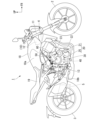
- FIG. 1 is a right side view of a motorcycle according to an embodiment.
- FIG. 2 is a cross-sectional view showing a portion of the power unit according to the embodiment.
- 1 is a cross-sectional view showing a clutch control device according to a first embodiment.
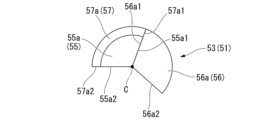
- FIG. 2 is a cross-sectional view of the release shaft of the first embodiment.
- FIG. 5 is a cross-sectional view of the release shaft shown in FIG. 4, illustrating the actuation of the upper release shaft and the lower release shaft by the clutch actuator.
- FIG. 5 is a cross-sectional view of the release shaft shown in FIG. 4, illustrating the manual actuation of the intermediate release shaft and the lower release shaft. 5 is a cross-sectional view of the release shaft shown in FIG.
- FIG. 2 is a perspective view showing an intermediate release shaft of the first embodiment.
- FIG. 2 is a right side view showing the clutch cover and the clutch actuator of the first embodiment.
- FIG. 2 is a block diagram of the transmission system according to the first embodiment.
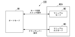
- 5 is an explanatory diagram showing a transition of a clutch control mode of the motorcycle according to the first embodiment.
- FIG. FIG. 4 is a cross-sectional view showing a clutch control device according to a second embodiment.
- FIG. 1 is a right side view of a motorcycle according to an embodiment.
- the motorcycle 1 of this embodiment is an example of a saddle-ride type vehicle.
- the motorcycle 1 includes a front wheel 2, a rear wheel 3, a body frame 10, a power unit 20, and a clutch control device 50.
- the body frame 10 includes a head pipe 11, a main frame 12, a pivot frame 13, etc., which are joined together by welding or the like.
- the head pipe 11 is provided at the front end of the body frame 10.
- the head pipe 11 supports the steering stem of the front wheel suspension 4.
- the front wheel 2 is supported by the front wheel suspension 4.
- the main frame 12 extends rearward and downward from the head pipe 11.
- the pivot frame 13 extends downward from the rear end of the main frame 12.
- the front end of the swing arm 5 is supported at the bottom of the pivot frame 13 so that it can swing.
- the rear wheel 3 is supported at the rear end of the swing arm 5. Note that the body frame 10 is not limited to the above configuration.
- a fuel tank 18 is disposed above the main frame 12.
- a seat 19 is disposed behind the fuel tank 18.
- a knee-grip portion 18a is formed at the rear of the fuel tank 18, recessed inward in the vehicle width direction.
- the knee-grip portions 18a are formed on both the left and right sides of the fuel tank 18.
- the knee-grip portions 18a are formed so as to be positioned on the inside of the left and right knees of the driver seated on the seat 19.
- a step 18b is disposed below the seat 19. The driver places his or her feet on the step 18b.
- the power unit 20 is supported on the body frame 10 so that it cannot be displaced relative to the vehicle.
- the power unit 20 integrally comprises an engine 21, a transmission 25, and a clutch device 40.
- the engine 21 is provided at the front of the power unit 20.
- the transmission 25 is provided at the rear of the power unit 20.
- the engine 21 comprises a crankshaft extending in the vehicle width direction, a crankcase 22 that houses the crankshaft, and a cylinder 23 that stands upward and forward from the crankcase 22.
- the crankcase 22 is disposed below the main frame 12 in a side view.
- the cylinder 23 is integrally connected to the crankcase 22.
- a piston is fitted within the cylinder 23. The reciprocating motion of the piston is converted into the rotational motion of the crankshaft via a connecting rod.
- the crankcase 22 is made of metal.
- FIG. 2 is a cross-sectional view showing a part of the power unit according to the embodiment.
- the transmission 25 is housed in the rear of the crankcase 22.
- the rear of the crankcase 22 also serves as a transmission case 22a that houses the transmission 25.
- the transmission 25 is a stepped transmission having a main shaft 26 and a countershaft 27 rotatably supported by the transmission case 22a, a group of speed change gears 28 that straddle the main shaft 26 and the countershaft 27, and a change mechanism 29 that switches the gear pairs used for power transmission between the main shaft 26 and the countershaft 27 in the group of speed change gears 28.
- the main shaft 26 and the countershaft 27 each extend in the vehicle width direction.
- the countershaft 27 constitutes the output shaft of the power unit 20.
- the countershaft 27 protrudes to the left of the transmission case 22a and is coupled to a drive sprocket.
- the rotation of the countershaft 27 is transmitted from the left side of the transmission case 22a to the rear wheel 3 via a chain drive type power transmission mechanism.
- the main shaft 26 and counter shaft 27 are arranged side by side behind the crankshaft.
- a clutch device 40 is connected to the right end of the main shaft 26. The rotational power of the crankshaft is transmitted to the main shaft 26 via the clutch device 40, and is transmitted from the main shaft 26 to the counter shaft 27 via any gear pair of the transmission gear set 28.
- the change mechanism 29 is housed in the transmission case 22a.
- the change mechanism 29 has a hollow cylindrical shift drum 29b that is parallel to the main shaft 26 and the counter shaft 27.
- the change mechanism 29 operates a plurality of shift forks 29c by the rotation of the shift drum 29b.
- the shift forks 29c operate according to the pattern of lead grooves formed on the outer periphery of the shift drum 29b.
- the change mechanism 29 switches the gear pairs used for power transmission between the main shaft 26 and the counter shaft 27 in the transmission gear group 28 by the operation of the shift forks 29c.
- a clutch cover 30 is connected to the transmission case 22a.
- the clutch cover 30 is located to the right of the transmission case 22a and connected to the crankcase 22.
- the clutch cover 30 is located on an extension of the main shaft 26.
- a clutch chamber is defined between the clutch cover 30 and the crankcase 22.
- a shaft insertion portion 36 through which the release shaft 53 passes is formed in the clutch cover 30 (see Figure 3).
- the clutch device 40 is a multi-plate friction clutch that connects and disconnects the power transmission between the crankshaft of the engine 21 and the main shaft 26 of the transmission 25.
- the clutch device 40 is disposed in a clutch chamber between the clutch cover 30 and the crankcase 22.
- the clutch device 40 is a wet multi-plate clutch in which multiple clutch plates 43 are stacked in the axial direction.
- the clutch device 40 includes a clutch outer 41, a clutch center 42, and multiple clutch plates 43.
- the clutch outer 41 is driven by constant transmission of rotational power from the crankshaft.
- the clutch center 42 is disposed within the clutch outer 41 and is supported by the main shaft 26 so as to be rotatable integrally therewith.
- a plurality of clutch plates 43 are stacked between the clutch outer 41 and the clutch center 42. The plurality of clutch plates 43 frictionally engage the clutch outer 41 and the clutch center 42.
- a pressure plate 44 of approximately the same diameter as the clutch plates 43 is disposed to the right (outside in the vehicle width direction) of the stacked clutch plates 43.
- the pressure plate 44 is urged leftward by the elastic load of a clutch spring 45, causing the stacked clutch plates 43 to press together (frictionally engage). This places the clutch device 40 in a connected state that allows power transmission.
- the clutch device 40 is a normally closed clutch that is normally in a connected state when there is no external input.
- the clutch plates 43 are released from the pressure contact (frictional engagement) by the operation of a release mechanism 51 inside the clutch cover 30.
- the release mechanism 51 is operated by at least one of the following: the operation of the clutch lever (clutch operator) by the occupant, and the application of torque by the clutch actuator 60.
- the clutch control device 50 of the first embodiment includes a release mechanism 51 and a clutch actuator 60 that outputs a driving force for actuating the clutch device 40.
- the release mechanism 51 includes a lifter shaft 52 and a release shaft 53.
- the lifter shaft 52 has a central axis along the vehicle width direction.
- the lifter shaft 52 is held in the right side of the main shaft 26 so that it can reciprocate in the vehicle width direction.
- the release shaft 53 has a central axis C along a direction perpendicular to the vehicle width direction.
- the release shaft 53 is held rotatably in the clutch cover 30.
- the release shaft 53 is tilted backwards in the axial direction so that the upper end is located rearward of the lower end when viewed in the axial direction of the main shaft 26 (when viewed from the side of the vehicle).
- the axial direction of the release shaft 53 is simply referred to as the axial direction.
- the clockwise direction when viewed from above along the axial direction is simply referred to as the clockwise direction
- the opposite direction to the clockwise direction is referred to as the counterclockwise direction.
- the upper part of the release shaft 53 protrudes outside the clutch cover 30.
- a driven clutch lever 58 is attached to the upper part of the release shaft 53 so as to be able to rotate integrally with it.
- the driven clutch lever 58 is connected to the clutch lever via an operating cable.
- the lower part of the release shaft 53 is located inside the clutch cover 30.
- the lower part of the release shaft 53 is provided with an eccentric cam portion 54.
- the eccentric cam portion 54 engages with the right end portion of the lifter shaft 52.
- the release shaft 53 rotates around the central axis C, and the eccentric cam portion 54 moves the lifter shaft 52 to the right.
- the lifter shaft 52 is capable of reciprocating integrally with the pressure plate 44 of the clutch device 40. Therefore, when the lifter shaft 52 moves to the right, the pressure plate 44 moves to the right against the biasing force of the clutch spring 45. This releases the frictional engagement between the stacked clutch plates 43. This causes the normally closed clutch device 40 to enter a disconnected state in which power cannot be transmitted.
- FIG. 3 is a cross-sectional view showing the clutch control device of the first embodiment. Note that FIG. 3 shows a cross section including the rotation axis of each rotor of the clutch actuator 60.
- the release shaft 53 is divided into a plurality of elements so that it can rotate upon receiving input from the clutch actuator 60 and input by the driver's operation separately.
- the release shaft 53 includes an upper release shaft 55 (first release shaft) constituting the upper part of the release shaft 53, a lower release shaft 56 (third release shaft) constituting the lower part of the release shaft 53, and an intermediate release shaft 57 (second release shaft).
- the intermediate release shaft 57 is disposed across the lower end of the upper release shaft 55 and the upper end of the lower release shaft 56.
- the upper release shaft 55 is cylindrical. The upper end of the upper release shaft 55 protrudes outward from the unit case 70 of the clutch actuator 60.
- the driven clutch lever 58 is supported at the upper end of the upper release shaft 55 so that it can rotate integrally with the upper release shaft 55.
- the upper release shaft 55 rotates when it receives an operating force from the driver via a clutch lever or the like.
- a return spring is attached to the driven clutch lever 58. The return spring applies a biasing force to the driven clutch lever 58 in the opposite direction to the rotation caused by the operation of the clutch lever (rotation in the clutch disengagement direction).
- the lower release shaft 56 is cylindrical.
- the lower part of the lower release shaft 56 is located inside the clutch cover 30.
- the lower part of the lower release shaft 56 is rotatably supported by the clutch cover 30.
- An eccentric cam portion 54 is formed on the lower release shaft 56 (see FIG. 2).
- a lower return spring is attached to the lower end of the lower release shaft 56.
- the lower return spring applies a biasing force to the lower release shaft 56 in the opposite direction to the rotation in the clutch disengagement direction.
- the upper part of the lower release shaft 56 protrudes to the outside of the clutch cover 30 through the shaft insertion portion 36 of the clutch cover 30.
- the upper part of the lower release shaft 56 faces inside the gear case 71 of the clutch actuator 60.
- FIG. 4 is a cross-sectional view of the release shaft of the first embodiment showing the cams on the upper release shaft, the lower release shaft, and the middle release shaft.
- the lower end of the upper release shaft 55 is provided with a manual side engaged portion 55a extending in the axial direction.
- the upper end of the lower release shaft 56 is provided with an engaging portion 56a extending in the axial direction.
- the manual side engaged portion 55a and the engaging portion 56a are each formed in a sector-shaped cross section.
- the manual side engaged portion 55a and the engaging portion 56a overlap each other in the axial direction and face each other in the circumferential direction. This allows the first engaged surface 55a1 facing the clockwise direction of the manual side engaged portion 55a to press the first engaging surface 56a1 facing the counterclockwise direction of the engaging portion 56a, thereby rotating the lower release shaft 56 in the clockwise direction (see Figure 5).
- the second engaged surface 55a2 facing the counterclockwise direction of the manual side engaged portion 55a and the second engaging surface 56a2 facing the clockwise direction of the engaging portion 56a are spaced apart from each other in the circumferential direction.
- FIG. 8 is a perspective view showing the intermediate release shaft of the first embodiment. 3 and 8, the intermediate release shaft 57 is cylindrical.
- the intermediate release shaft 57 can be inserted through the engaging portions of the lower end of the upper release shaft 55 and the upper end of the lower release shaft 56.
- the intermediate release shaft 57 includes a peripheral wall 81 having a first through hole 83 through which the lower release shaft 56 is inserted, a bearing holder 82 having a second through hole 84 connected to the first through hole 83, and a control side engaged portion 57a that faces the engaging portion 56a of the lower release shaft 56 in the circumferential direction.
- the surrounding wall 81 is formed in a cylindrical shape.
- the lower release shaft 56 is inserted into the inside of the surrounding wall 81 so as to protrude upward.
- the lower half of the engagement portion 56a of the lower release shaft 56 is located in the first through hole 83.
- the bearing holder 82 is formed in a cylindrical shape.
- the bearing holder 82 is connected to the upper end of the peripheral wall 81.
- the second through hole 84 is directly connected to the first through hole 83 and is formed with a larger diameter than the first through hole 83.
- the inner diameter of the bearing holder 82 is larger than the inner diameter of the peripheral wall 81.
- the inner circumferential surface of the bearing holder 82 is connected to the inner circumferential surface of the peripheral wall 81 via an annular stepped surface facing upward.
- the second through hole 84 is located at the portion of the lower release shaft 56 that protrudes upward from the first through hole 83.
- the lower end of the upper release shaft 55 is located at the second through hole 84.
- the driven gear 67 which will be described later, is integrally formed with the bearing holder 82.
- a bearing 90 is held inside the bearing holder 82.
- the bearing 90 is a rolling bearing 90 (ball bearing).
- the bearing 90 holds the engaging portion 56a of the lower release shaft 56 and the manual side engaged portion 55a of the upper release shaft 55 so that they can rotate relative to the intermediate release shaft 57.
- the bearing 90 is prevented from falling out from inside the bearing holder 82 by a C-ring 85 attached to the inner peripheral surface of the bearing holder 82.
- control side engaged portion 57a protrudes radially inward from the surrounding wall 81.
- the control side engaged portion 57a extends in the axial direction and is formed in a sector shape in cross section.
- the control side engaged portion 57a is located below the manual side engaged portion 55a of the upper release shaft 55.
- the control side engaged portion 57a overlaps with the engaging portion 56a of the lower release shaft 56 in the axial direction and faces each other in the circumferential direction.
- control side engaged portion 57a of the intermediate release shaft 57 and the engaging portion 56a of the lower release shaft 56 overlap each other in the axial direction and face each other in the circumferential direction. This allows the first engaged surface 57a1 facing the clockwise direction of the control side engaged portion 57a to press the first engaging surface 56a1 of the engaging portion 56a, thereby rotating the lower release shaft 56 in the clockwise direction (see Figure 6).
- the control side engaged portion 57a avoids the manual side engaged portion 55a of the upper release shaft 55 in the axial direction. This allows the intermediate release shaft 57 to rotate the lower release shaft 56 independently of the upper release shaft 55. In addition, the upper release shaft 55 can rotate the lower release shaft 56 independently of the intermediate release shaft 57 (see Figure 7).
- the second engaged surface 57a2 of the control side engaged portion 57a, which faces in the counterclockwise direction, and the second engaging surface 56a2 of the engaging portion 56a are spaced apart from each other in the circumferential direction. This allows the lower release shaft 56 to rotate in the clockwise direction independently of the intermediate release shaft 57 when an input is applied to the lower release shaft 56 without passing through the intermediate release shaft 57.
- the clutch actuator 60 controls the operating torque applied to the release shaft 53 to engage and disengage the clutch device 40.
- the clutch actuator 60 is attached to the top of the clutch cover 30.
- the clutch actuator 60 includes a motor 61 as a drive source, a reduction mechanism 62 that transmits the drive force of the motor 61 to the release shaft 53, and a unit case 70 that houses the motor 61 and the reduction mechanism 62.
- the motor 61 is, for example, a DC motor.
- the motor 61 is arranged so that the rotation axis of the rotor is aligned with the axial direction of the release shaft 53.
- the motor 61 is arranged so that its rotation shaft 61a protrudes upward and downward.
- a single clutch actuator 60 is equipped with a pair of motors 61.
- the pair of motors 61 are aligned in the front-to-rear direction. Control of the pair of motors 61 will be described later.
- the reduction mechanism 62 reduces the speed of the rotational power output from the motor 61 and transmits it to the release shaft 53.
- the reduction mechanism 62 includes a gear train 63. Each gear of the gear train 63 has a rotation axis along the axial direction.
- the gear train 63 includes a drive gear 61b, a first reduction gear 64b, a first small diameter gear 64c, a second reduction gear 65b, a second small diameter gear 65c, a third reduction gear 66b, a third small diameter gear 66c, and a driven gear 67.
- the drive gear 61b is integrally formed on the rotating shaft 61a of each motor 61.
- a first reduction gear 64b is arranged between the two drive gears 61b.
- the first reduction gear 64b meshes with each drive gear 61b.
- the first reduction gear 64b reduces the rotation of each drive gear 61b.
- the first small diameter gear 64c is arranged coaxially with the first reduction gear 64b.
- the second reduction gear 65b meshes with the first small diameter gear 64c.
- the second reduction gear 65b reduces the rotation of the first small diameter gear 64c.
- the second small diameter gear 65c is arranged coaxially with the second reduction gear 65b.
- the third reduction gear 66b meshes with the second small diameter gear 65c.
- the third reduction gear 66b reduces the rotation speed of the second small diameter gear 65c.
- the third small diameter gear 66c is arranged coaxially with the third reduction gear 66b.
- the driven gear 67 meshes with the second small diameter gear 65c.
- the driven gear 67 reduces the rotation speed of the second small diameter gear 65c.
- the first reduction gear 64b and the first small diameter gear 64c are each arranged to be rotatable integrally with the first support shaft 64a.
- the first reduction gear 64b, the first small diameter gear 64c, and the first support shaft 64a constitute the first reduction shaft 64.
- the first reduction shaft 64 has a central axis that runs along the axial direction.
- the second reduction gear 65b and the second small diameter gear 65c are each arranged so as to be rotatable integrally with the second support shaft 65a.
- the second reduction gear 65b, the second small diameter gear 65c, and the second support shaft 65a constitute the second reduction shaft 65.
- the second reduction shaft 65 has a central axis that runs along the axial direction.
- the third reduction gear 66b and the third small diameter gear 66c wrap around each other in the axial direction.
- the third reduction gear 66b and the third small diameter gear 66c are formed integrally with each other.
- the third reduction gear 66b and the third small diameter gear 66c are each provided so as to be able to rotate integrally with the third support shaft 66a.
- the third reduction gear 66b, the third small diameter gear 66c, and the third support shaft 66a form the third reduction shaft 66.
- the third reduction shaft 66 has a central axis line along the axial direction.
- the third reduction shaft 66 is provided with a rotation angle sensor 68 that detects the rotation angle of the third reduction shaft 66.
- the third reduction shaft 66 is located in front of the second reduction shaft 65.
- the second reduction shaft 65 is located in front of the first reduction shaft 64.
- In front of the third reduction shaft 66 is the release shaft 53.
- the central axis C of the release shaft 53 and the central axes of the reduction shafts 64, 65, and 66 are aligned on the same straight line extending in the front-to-rear direction when viewed in the axial direction.
- the first support shaft 64a, the second support shaft 65a, and the third support shaft 66a are each rotatably supported by the unit case 70.
- the third reduction gear 66b is a sector gear centered on the third support shaft 66a.
- the third reduction gear 66b is arranged to extend forward of the third support shaft 66a.
- the driven gear 67 is arranged to be rotatable integrally with the intermediate release shaft 57 of the release shaft 53.
- the driven gear 67 is a sector-shaped gear centered on the release shaft 53.
- the driven gear 67 is arranged to extend forward of the release shaft 53.
- the third reduction gear 66b and the driven gear 67 are sector-shaped gears, which allows the reduction mechanism 62 and the clutch actuator 60 to be made more compact. In other words, even when a large-diameter reduction gear is provided to increase the reduction ratio, by cutting out the area other than the meshing range of the reduction gear to make it sector-shaped, it is possible to suppress the outward protrusion of the reduction mechanism 62 in the vehicle width direction, and also to reduce the weight of the reduction mechanism 62.
- the reduction mechanism 62 connects the motor 61 and the release shaft 53 so that they can be constantly linked together. This creates a system in which the clutch actuator 60 directly connects and disconnects the clutch device 40.
- FIG. 9 is a right side view showing the clutch cover and the clutch actuator in the first embodiment. 3 and 9, the unit case 70 is fixed to the clutch cover 30.
- the unit case 70 includes a gear case 71 and a motor case 75.
- the gear case 71 rotatably supports the first support shaft 64a, the second support shaft 65a, and the third support shaft 66a.
- the gear case 71 houses the gear train 63.
- the gear case 71 is formed in two stages, upper and lower, in the axial direction.
- the upper part of the gear case 71 will be referred to as the upper stage 71U
- the lower part of the gear case 71 will be referred to as the lower stage 71L.
- the upper stage 71U is shifted rearward along a plane perpendicular to the axial direction relative to the lower stage 71L.
- a motor case 75 extending along the axial direction is connected below the lower stage 71L.
- the upper stage portion 71U has a rectangular shape that is long in the front-rear direction when viewed in the axial direction.
- the upper stage portion 71U forms an upper stage gear accommodating chamber 72U.
- the upper stage gear accommodating chamber 72U accommodates the first small diameter gear 64c, the second reduction gear 65b, the second small diameter gear 65c, the third reduction gear 66b, the third small diameter gear 66c, and the driven gear 67 of the gear train 63.
- the upper stage portion 71U of the gear case 71 is divided into upper and lower parts by a dividing plane perpendicular to the axial direction.
- the lower part of the upper stage portion 71U will be referred to as the upper stage portion main body 71Ua, and the upper part of the upper stage portion 71U will be referred to as the case upper cover 71Ub.
- the upper stage portion main body 71Ua is open upward.
- the case upper cover 71Ub closes the upper opening of the upper body 71Ua from above.
- the upper section body 71Ua rotatably supports the first reduction shaft 64 at a location between the first reduction gear 64b and the first small diameter gear 64c via a rolling bearing.
- the upper section body 71Ua rotatably supports the lower end of the second reduction shaft 65 via a rolling bearing.
- the upper section body 71Ua rotatably supports the lower end of the third reduction shaft 66 via a rolling bearing.
- the upper section body 71Ua rotatably supports the lower end (surrounding wall) of the intermediate release shaft 57 via a rolling bearing.
- the case upper cover 71Ub rotatably supports the upper end of the first reduction shaft 64 via a rolling bearing.
- the case upper cover 71Ub rotatably supports the upper end of the second reduction shaft 65 via a rolling bearing.
- the case upper cover 71Ub rotatably supports a portion of the third reduction shaft 66 located above the third reduction gear 66b and the third small diameter gear 66c via a rolling bearing.
- the case upper cover 71Ub rotatably supports the upper release shaft 55 via a rolling bearing.
- the case upper cover 71Ub rotatably supports the upper end (bearing holder) of the intermediate release shaft 57 via a bearing.
- the lower section 71L has an elliptical shape that is long in the front-rear direction when viewed in the axial direction.
- the lower section 71L forms a lower gear storage chamber 72L.
- the upper gear storage chamber 72U and the lower gear storage chamber 72L are separated by a partition wall.
- the lower gear storage chamber 72L stores the drive gear 61b and the first reduction gear 64b of the rotating shaft 61a of each motor 61 in the gear train 63.
- the lower section 71L of the gear case 71 is divided into upper and lower sections by a dividing plane perpendicular to the axial direction.
- the upper part of the lower section 71L will be referred to as the lower section main body 71La, and the lower part of the lower section 71L will be referred to as the case lower cover 71Lb.
- the lower section main body 71La is open downward.
- the case lower cover 71Lb closes the lower part of the lower section main body 71La from below.
- the motor case 75 forms a motor housing chamber 76 that houses two motors 61.
- the motor housing chamber 76 houses two cylindrical motors 61 arranged in parallel.
- the motor case 75 is tubular with a bottom and an elliptical cross section.
- a case bottom cover 71Lb is integrally formed on the upper part of the motor case 75 to enlarge the cross-sectional shape.
- the motor case 75 and case bottom cover 71Lb are integrally formed with each other to form a lower case body 77L.
- the upper body 71Ua and the lower body 71La are integrally formed with each other to form the upper case body 77U.
- the upper case cover 71Ub is attached from above to the upper case body 77U, and the upper gear storage chamber 72U is formed between the upper case body 77U and the upper case cover 71Ub.
- the lower case cover 71Lb of the lower case body 77L is attached from below to the upper case body 77U, and the lower gear storage chamber 72L is formed between the upper case body 77U and the lower case cover 71Lb.
- the lower case body 77L and the upper case body 77U are positioned relative to each other via a pair of front and rear knock pins 79.
- the lower part of each knock pin 79 is fitted into a retaining hole in the lower case body 77L.
- the upper part of each knock pin 79 is inserted into a fitting hole in the upper case body 77U.
- the gear case 71 is formed with a first opening 73a and a second opening 73b through which the release shaft 53 is inserted.
- the first opening 73a faces the shaft insertion portion 36 of the clutch cover 30.
- the first opening 73a penetrates the upper stage main body 71Ua in the axial direction.
- the gear case 71 receives the lower release shaft 56 protruding from the clutch cover 30 through the first opening 73a.
- the second opening 73b penetrates the case upper cover 71Ub in the axial direction coaxially with the first opening 73a.
- the inner surface of the second opening 73b rotatably supports the upper release shaft 55 of the release shaft 53 with the release shaft 53 protruding outside the gear case 71 through the second opening 73b.
- the gear case 71 rotatably holds the intermediate release shaft 57 between the first opening 73a and the second opening 73b.
- the gear case 71 is fastened to the clutch cover 30 by bolts B1 that run along the axial direction.
- the motor case 75 is fastened to the clutch cover 30 by bolts B2 that run perpendicular to the axial direction.
- a straight release shaft 53 is formed in which the upper release shaft 55, the intermediate release shaft 57 and the lower release shaft 56 are interconnected.
- the control unit 101 controls the operation of the ignition device 108 and the fuel injection device 109, and also controls the operation of the clutch actuator 60.
- the control unit 101 controls the operation of the clutch actuator 60, based on detection information from the acceleration sensor 102, the gear position sensor 103, and the shift load sensor 104 (e.g., a torque sensor), as well as various vehicle state detection information from the throttle opening sensor 105, the vehicle speed sensor 106, the engine speed sensor 107, etc.
- the acceleration sensor 102 detects the behavior of the vehicle body.
- the gear position sensor 103 detects the gear position from the rotation angle of the shift drum 29b.
- the shift load sensor 104 detects the operating torque input to the shift spindle 29a (see Figure 2) of the change mechanism 29.
- the throttle opening sensor 105 detects the throttle opening.
- the vehicle speed sensor 106 detects the vehicle speed.
- the engine speed sensor 107 detects the engine speed.
- FIG. 11 is an explanatory diagram showing the transition of the clutch control mode of the motorcycle according to the first embodiment.
- the transmission system 100 of this embodiment has three clutch control modes.
- the clutch control modes include an auto mode M1 for automatic control, a manual mode M2 for manual operation, and a manual intervention mode M3 for temporary manual operation.
- the clutch control mode transitions between the three modes as appropriate in response to the operation of a clutch control mode changeover switch 49 (see Fig. 11) and a clutch operator.
- the manual mode M2 and the manual intervention mode M3 are referred to as a manual system M2A.
- Auto mode M1 is a mode in which the clutch capacity appropriate for the driving conditions is calculated in accordance with automatic starting and shifting control, and the clutch device 40 is controlled.
- Manual mode M2 is a mode in which the clutch capacity is calculated in accordance with a clutch operation instruction from the occupant, and the clutch device 40 is controlled.
- Manual intervention mode M3 is a temporary manual operation mode in which a clutch operation instruction from the occupant is accepted during auto mode M1, the clutch capacity is calculated from the clutch operation instruction, and the clutch device 40 is controlled. Note that during manual intervention mode M3, for example, if the occupant stops operating the clutch operator (completely released state) for a specified time, the mode may be set to return to auto mode M1.
- the transmission system 100 when the transmission system 100 is started, it starts control in auto mode M1 with the clutch on (connected state). Also, when the engine 21 is stopped (system off), the transmission system 100 is set to return to clutch on in auto mode M1. In a normally closed clutch device 40, when the clutch is on, there is no need to supply power to the motor 61 of the clutch actuator 60. On the other hand, when the clutch device 40 is in the clutch off state (disconnected state), power supply to the motor 61 is maintained.
- Auto mode M1 is based on automatic clutch control. In auto mode M1, motorcycle 1 can be driven without lever operation. In auto mode M1, clutch capacity is controlled based on throttle opening, engine RPM, vehicle speed, shift sensor output, etc. This allows motorcycle 1 to start without engine stall by simply operating the throttle. Motorcycle 1 can also be changed gears by simply shifting the gears. In addition, auto mode M1 switches to manual intervention mode M3 when the rider grips the clutch lever.
- the clutch capacity can be controlled by the rider operating a lever. That is, in manual mode M2, the clutch device 40 can be engaged or disengaged by the rider operating a lever. Auto mode M1 and manual mode M2 can be switched back and forth. This switching is performed, for example, by operating the clutch control mode changeover switch 49 (see FIG. 10) while the motorcycle 1 is stopped and the transmission 25 is in neutral.
- the transmission system 100 may also be provided with an indicator that shows that the transmission is in the manual state when transitioning to the manual system M2A (manual mode M2 or manual intervention mode M3).
- Manual mode M2 is based on manual clutch control.
- the clutch capacity can be controlled according to the operating angle of the clutch lever (i.e., the operating angle of the driven clutch lever 58). This allows the driver to control the engagement and disengagement of the clutch device 40 at will.
- the operating angle of the driven clutch lever 58 is referred to as the driven clutch lever operating angle.
- auto mode M1 the clutch actuator 60 automatically engages and disengages the clutch device 40.
- auto mode M1 manual clutch operation can be performed on the clutch lever to temporarily intervene manually in the automatic control of the clutch device 40 (manual intervention mode M3).
- the clutch lever is connected via an operating cable to a driven clutch lever 58 attached to a release shaft 53 of the clutch device 40.
- the driven clutch lever 58 is attached to the upper end of the release shaft 53 so as to be integrally rotatable.
- a handle switch attached to the steering handle is provided with a clutch control mode changeover switch 49. This allows the occupant to easily switch the clutch control mode during normal driving.
- a pair of motors 61 in the clutch actuator 60 may cooperate to drive the release shaft 53 (to connect and disconnect the clutch device 40).
- the load shared by each of the two motors 61 is halved, and each motor 61 can be made smaller.
- This increases the degree of freedom in the layout of the motor 61 compared to a configuration in which the clutch actuator 60 includes a single motor 61. Therefore, even when the clutch actuator 60 is disposed on the outer side of the power unit 20, it is easy to prevent the clutch actuator 60 from protruding outward in the vehicle width direction. Therefore, it becomes possible to substantially reduce the size of the clutch actuator 60.
- one of the multiple (two) motors 61 is used as the drive source for the release shaft 53, and the remaining one may be used for another purpose.
- the remaining one motor 61 may refrain from operating as a fail-safe, or may be used as a current sensor.
- the clutch control device 50 of this embodiment has a lower release shaft 56 that has an engagement portion 56a that axially wraps around the upper release shaft 55 and the intermediate release shaft 57 and faces them in the circumferential direction, and the engagement portion 56a rotates to operate the clutch device 40 by receiving the rotation of the upper release shaft 55 and the rotation of the intermediate release shaft 57 individually, and a bearing 90 that holds the engagement portion 56a.
- the engagement portion 56a of the lower release shaft 56 is held by the bearing 90, and the bearing 90 is arranged to surround the engagement points of the upper release shaft 55 and the intermediate release shaft 57 with the lower release shaft 56.
- each release shaft 55 to 57 is restricted by the bearing 90, and the upper release shaft 55 and the intermediate release shaft 57 can be prevented from falling relative to the lower release shaft 56.
- This allows the rotation of the upper release shaft 55 to be efficiently transmitted to the lower release shaft 56.
- the rotation of the intermediate release shaft 57 can be efficiently transmitted to the lower release shaft 56. Therefore, the manual connection/disconnection operation of the clutch device 40 that rotates the lower release shaft 56 via the upper release shaft 55 and the automatic connection/disconnection operation of the clutch device 40 that rotates the lower release shaft 56 via the intermediate release shaft 57 can be smoothly performed in conjunction with each other.
- the upper release shaft 55 has a manual side engaged portion 55a that faces the engaging portion 56a in the circumferential direction.
- the bearing 90 holds the engaging portion 56a and the manual side engaged portion 55a. This configuration effectively prevents the upper release shaft 55 from falling relative to the lower release shaft 56. Therefore, the rotation of the upper release shaft 55 can be efficiently transmitted to the lower release shaft 56, making it possible to manually and smoothly engage and disengage the clutch device 40.
- the intermediate release shaft 57 has a driven gear 67 that transmits the driving force from the clutch actuator 60, a control side engaged portion 57a that faces the engaging portion 56a in the circumferential direction, a surrounding wall 81 in which a first through hole 83 through which the lower release shaft 56 is inserted is formed, and a bearing holding portion 82 in which a second through hole 84 that is connected to the first through hole 83 and has a larger diameter than the first through hole 83 is formed and holds a bearing 90 inside.
- the bearing 90 can be held between the upper release shaft 55 and the intermediate release shaft 57 through which the upper release shaft 55 is inserted, and a clutch control device 50 that achieves the above-mentioned effects can be obtained without providing a bearing holding structure on the casing of the clutch control device 50, etc.
- the power unit 20 of the embodiment can be configured by replacing the clutch cover 30 and release shaft 53 and retrofitting the clutch actuator 60 to a manual clutch power unit in which the clutch device 40 is engaged and disengaged by the driver rather than electrically controlled.
- This makes it possible to attach the clutch actuator 60 to power units of different models.
- This makes it possible to share the clutch actuator 60 between multiple models and easily configure a semi-automatic transmission system 100 (automatic clutch type transmission system).
- a clutch control device 150 of the second embodiment includes a front-stage release shaft 156A, a rear-stage release shaft 156B, and a transmission unit 159, instead of the lower release shaft 56 of the first embodiment. Note that the configuration other than that described below is the same as that of the first embodiment.
- FIG. 12 is a cross-sectional view showing a clutch control device according to the second embodiment.
- the front stage release shaft 156A and the rear stage release shaft 156B each have a central axis that is aligned in a direction perpendicular to the vehicle width direction.
- the front stage release shaft 156A and the rear stage release shaft 156B are arranged in parallel with their central axes shifted from each other.
- the front stage release shaft 156A and the rear stage release shaft 156B are each rotatably supported by the clutch cover 30.
- An upper portion of the front stage release shaft 156A protrudes outside the clutch cover 30.
- the entire rear stage release shaft 156B is located inside the clutch cover 30.
- the transmission unit 159 transmits the rotation of the front-stage release shaft 156A to the rear-stage release shaft 156B.
- the transmission unit 159 includes a front-stage gear 159a that rotates integrally with the front-stage release shaft 156A, and a rear-stage gear 159b that meshes with the front-stage gear 159a and rotates integrally with the rear-stage release shaft 156B.
- the gear ratio of the front-stage gear 159a and the rear-stage gear 159b is not particularly limited.
- the front-stage gear 159a and the rear-stage gear 159b are located inside the clutch cover 30.
- the upper release shaft 55, the intermediate release shaft 57 and the front-stage release shaft 156A are connected to each other in a straight line.
- the clutch control device 150 of this embodiment provides the same effects as the first embodiment.
- the release shaft rotatably supported on the clutch cover 30 is composed of a front-stage release shaft 156A and a rear-stage release shaft 156B that are arranged in parallel with their central axes offset from each other. This makes it possible to arbitrarily set the position of the clutch actuator 60, including the upper release shaft 55 and intermediate release shaft 57 that engage with the front-stage release shaft 156A, relative to the lifter shaft 52. This improves the freedom of positioning of the clutch actuator 60.
- the release mechanism 51 in the embodiment is an eccentric cam mechanism, but the release mechanism may be a mechanism equipped with a rack and pinion, a feed screw, etc.
- the mechanism connecting the clutch lever and the driven clutch lever 58 is not limited to an operating cable, and may be a mechanism equipped with a rod, link, etc.
- the clutch actuator 60 has a pair of motors 61, but the clutch actuator may have only one motor.
- the above-mentioned clutch control device allows smooth interoperation between the automatic and manual clutch device connection/disconnection operations.
Landscapes
- Engineering & Computer Science (AREA)
- General Engineering & Computer Science (AREA)
- Physics & Mathematics (AREA)
- Electromagnetism (AREA)
- Mechanical Engineering (AREA)
- Mechanical Operated Clutches (AREA)
Priority Applications (4)
| Application Number | Priority Date | Filing Date | Title |
|---|---|---|---|
| PCT/JP2023/010589 WO2024194925A1 (ja) | 2023-03-17 | 2023-03-17 | クラッチ制御装置 |
| EP23928510.9A EP4647627A4 (en) | 2023-03-17 | 2023-03-17 | CLUTCH CONTROL DEVICE |
| JP2025507906A JPWO2024194925A1 (https=) | 2023-03-17 | 2023-03-17 | |
| CN202380095588.0A CN120882984A (zh) | 2023-03-17 | 2023-03-17 | 离合器控制装置 |
Applications Claiming Priority (1)
| Application Number | Priority Date | Filing Date | Title |
|---|---|---|---|
| PCT/JP2023/010589 WO2024194925A1 (ja) | 2023-03-17 | 2023-03-17 | クラッチ制御装置 |
Publications (1)
| Publication Number | Publication Date |
|---|---|
| WO2024194925A1 true WO2024194925A1 (ja) | 2024-09-26 |
Family
ID=92841060
Family Applications (1)
| Application Number | Title | Priority Date | Filing Date |
|---|---|---|---|
| PCT/JP2023/010589 Ceased WO2024194925A1 (ja) | 2023-03-17 | 2023-03-17 | クラッチ制御装置 |
Country Status (4)
| Country | Link |
|---|---|
| EP (1) | EP4647627A4 (https=) |
| JP (1) | JPWO2024194925A1 (https=) |
| CN (1) | CN120882984A (https=) |
| WO (1) | WO2024194925A1 (https=) |
Cited By (2)
| Publication number | Priority date | Publication date | Assignee | Title |
|---|---|---|---|---|
| US20240317235A1 (en) * | 2023-03-21 | 2024-09-26 | GM Global Technology Operations LLC | Control of transitions between transmission states |
| EP4717941A1 (en) * | 2024-09-30 | 2026-04-01 | Honda Motor Co., Ltd. | Clutch control device and saddle riding vehicle |
Citations (3)
| Publication number | Priority date | Publication date | Assignee | Title |
|---|---|---|---|---|
| JP2005106246A (ja) | 2003-10-01 | 2005-04-21 | Suzuki Motor Corp | クラッチ操作装置 |
| JP2015148307A (ja) * | 2014-02-07 | 2015-08-20 | 本田技研工業株式会社 | クラッチレリーズ機構 |
| WO2022209708A1 (ja) * | 2021-03-31 | 2022-10-06 | 本田技研工業株式会社 | クラッチ制御装置 |
Family Cites Families (2)
| Publication number | Priority date | Publication date | Assignee | Title |
|---|---|---|---|---|
| JP4989296B2 (ja) * | 2007-04-27 | 2012-08-01 | 本田技研工業株式会社 | クラッチ操作機構 |
| FR3032757B1 (fr) * | 2015-02-13 | 2017-04-28 | Renault Sas | Dispositif de commande d'un embrayage a recepteur concentrique mecanique |
-
2023
- 2023-03-17 EP EP23928510.9A patent/EP4647627A4/en active Pending
- 2023-03-17 JP JP2025507906A patent/JPWO2024194925A1/ja active Pending
- 2023-03-17 CN CN202380095588.0A patent/CN120882984A/zh active Pending
- 2023-03-17 WO PCT/JP2023/010589 patent/WO2024194925A1/ja not_active Ceased
Patent Citations (3)
| Publication number | Priority date | Publication date | Assignee | Title |
|---|---|---|---|---|
| JP2005106246A (ja) | 2003-10-01 | 2005-04-21 | Suzuki Motor Corp | クラッチ操作装置 |
| JP2015148307A (ja) * | 2014-02-07 | 2015-08-20 | 本田技研工業株式会社 | クラッチレリーズ機構 |
| WO2022209708A1 (ja) * | 2021-03-31 | 2022-10-06 | 本田技研工業株式会社 | クラッチ制御装置 |
Non-Patent Citations (1)
| Title |
|---|
| See also references of EP4647627A1 |
Cited By (3)
| Publication number | Priority date | Publication date | Assignee | Title |
|---|---|---|---|---|
| US20240317235A1 (en) * | 2023-03-21 | 2024-09-26 | GM Global Technology Operations LLC | Control of transitions between transmission states |
| US12304493B2 (en) * | 2023-03-21 | 2025-05-20 | GM Global Technology Operations LLC | Control of transitions between transmission states |
| EP4717941A1 (en) * | 2024-09-30 | 2026-04-01 | Honda Motor Co., Ltd. | Clutch control device and saddle riding vehicle |
Also Published As
| Publication number | Publication date |
|---|---|
| EP4647627A1 (en) | 2025-11-12 |
| EP4647627A4 (en) | 2026-03-04 |
| JPWO2024194925A1 (https=) | 2024-09-26 |
| CN120882984A (zh) | 2025-10-31 |
Similar Documents
| Publication | Publication Date | Title |
|---|---|---|
| US8191443B2 (en) | Reverse inhibitor mechanism for regulating automatic transmission gear shifting, and method of assembling same | |
| WO2024194925A1 (ja) | クラッチ制御装置 | |
| CN101501358A (zh) | 双离合器装置 | |
| JP2008275084A (ja) | クラッチ操作機構 | |
| EP2567889A1 (en) | Gear shift control device of saddle ride type vehicle | |
| WO2024194918A1 (ja) | クラッチ制御装置 | |
| JP7829803B2 (ja) | クラッチアクチュエータの締結構造 | |
| EP2060431B1 (en) | Power unit for vehicle and vehicle therewith | |
| JP7462108B2 (ja) | クラッチ制御装置 | |
| JP3158452U (ja) | 車両用パワーユニットおよびそれを備えた車両 | |
| JP7462107B2 (ja) | クラッチ制御装置 | |
| JP2025137715A (ja) | クラッチ制御装置 | |
| JP2014070649A (ja) | 車両用動力伝達装置 | |
| JP2025096457A (ja) | 変速システム | |
| JP5396363B2 (ja) | アイドルストップ装置を備えた車両 | |
| WO2024201798A1 (ja) | クラッチ制御装置 | |
| JP7774740B2 (ja) | クラッチ制御装置 | |
| JP2001280489A (ja) | 自動二輪車用電動式変速装置 | |
| JP2004044520A (ja) | クラッチ機構 | |
| JP6487887B2 (ja) | 動力伝達装置 | |
| JP7566205B2 (ja) | クラッチ制御装置 | |
| JP2026062329A (ja) | クラッチ制御装置および鞍乗り型車両 | |
| WO2024143335A1 (ja) | クラッチ制御装置 | |
| JP2001208196A (ja) | 自動二輪車用電動式変速装置 | |
| JP2540808B2 (ja) | 手動変速機の変速操作機構 |
Legal Events
| Date | Code | Title | Description |
|---|---|---|---|
| 121 | Ep: the epo has been informed by wipo that ep was designated in this application |
Ref document number: 23928510 Country of ref document: EP Kind code of ref document: A1 |
|
| ENP | Entry into the national phase |
Ref document number: 2025507906 Country of ref document: JP Kind code of ref document: A |
|
| WWE | Wipo information: entry into national phase |
Ref document number: 2025507906 Country of ref document: JP |
|
| WWE | Wipo information: entry into national phase |
Ref document number: 202517080856 Country of ref document: IN |
|
| WWE | Wipo information: entry into national phase |
Ref document number: 202380095588.0 Country of ref document: CN |
|
| REG | Reference to national code |
Ref country code: BR Ref legal event code: B01A Ref document number: 112025018538 Country of ref document: BR |
|
| WWE | Wipo information: entry into national phase |
Ref document number: 2501006078 Country of ref document: TH |
|
| WWP | Wipo information: published in national office |
Ref document number: 202517080856 Country of ref document: IN |
|
| NENP | Non-entry into the national phase |
Ref country code: DE |
|
| WWP | Wipo information: published in national office |
Ref document number: 202380095588.0 Country of ref document: CN |
|
| WWP | Wipo information: published in national office |
Ref document number: 2023928510 Country of ref document: EP |