WO2024190814A1 - ダイナモメータシステム及びその暖機方法 - Google Patents
ダイナモメータシステム及びその暖機方法 Download PDFInfo
- Publication number
- WO2024190814A1 WO2024190814A1 PCT/JP2024/009713 JP2024009713W WO2024190814A1 WO 2024190814 A1 WO2024190814 A1 WO 2024190814A1 JP 2024009713 W JP2024009713 W JP 2024009713W WO 2024190814 A1 WO2024190814 A1 WO 2024190814A1
- Authority
- WO
- WIPO (PCT)
- Prior art keywords
- warm
- dynamometer
- period
- warming
- value
- Prior art date
- Legal status (The legal status is an assumption and is not a legal conclusion. Google has not performed a legal analysis and makes no representation as to the accuracy of the status listed.)
- Ceased
Links
Images


Classifications
-
- G—PHYSICS
- G01—MEASURING; TESTING
- G01M—TESTING STATIC OR DYNAMIC BALANCE OF MACHINES OR STRUCTURES; TESTING OF STRUCTURES OR APPARATUS, NOT OTHERWISE PROVIDED FOR
- G01M17/00—Testing of vehicles
- G01M17/007—Wheeled or endless-tracked vehicles
Definitions
- the present invention relates to a dynamometer system and a warm-up method thereof. More specifically, the present invention relates to a dynamometer system and a warm-up method thereof that can warm up a dynamometer for an appropriate period of time so as to obtain highly accurate results with little variation between tests.
- Chassis dynamometer systems are used in vehicle tests such as durability tests, exhaust purification performance evaluation tests, and fuel economy measurements. Chassis dynamometer systems are equipped with rollers on which the wheels of the vehicle under test are placed and a dynamometer connected to the rollers. The dynamometer and rollers are used to apply the running resistance that occurs during actual driving, such as rolling resistance and inertial resistance, to the vehicle running on the rollers, recreating conditions close to those of actual driving.
- chassis dynamometer system In order to perform highly accurate testing using such a chassis dynamometer system, mechanical components such as the dynamometer and rollers must be sufficiently warmed up before starting the test.
- a vehicle placed on the rollers is driven, and the driving force of the vehicle is used to rotate the dynamometer, thereby warming up the dynamometer along with the vehicle.
- the chassis dynamometer shown in Patent Document 1 uses a temperature sensor to measure the temperature of at least one of the roller surface or tire surface, thereby determining whether the space between the roller and tire has been sufficiently warmed up by the warm-up operation described above.
- the present invention aims to provide a dynamometer system and a method for warming up the dynamometer for an appropriate period of time.
- the present invention relates to a method for warming up a dynamometer system including rollers (e.g., rollers 1f, 1r described below) on which wheels (e.g., front wheels Wf and rear wheels Wr described below) of a vehicle (e.g., vehicle V described below) can be placed, a dynamometer (e.g., dynamometers 2f, 2r described below) connected to the rollers, and a force parameter acquisition device (e.g., speed sensors 3f, 3r, torque sensors 4f, 4r, and operation measurement system 7 described below) that acquires force parameter values that are correlated with forces acting on the rollers or the dynamometer.
- rollers e.g., rollers 1f, 1r described below
- wheels e.g., front wheels Wf and rear wheels Wr described below
- a vehicle e.g., vehicle V described below
- a dynamometer e.g., dynamometers 2f, 2r described below
- This warm-up method includes the steps of: performing a warm-up operation for a predetermined warm-up period, rotating the dynamometer so that the rotational speed of the roller or the dynamometer is maintained at a predetermined set speed (e.g., a warm-up set speed described below); acquiring the force parameter value for a judgment period set within the warm-up period; calculating an interval average value of the force parameter value for each of a plurality of average calculation intervals set within the judgment period; and judging the stable state of the warm-up object, including the dynamometer, based on the magnitude of variation of the plurality of interval average values within the judgment period.
- a predetermined set speed e.g., a warm-up set speed described below
- the warm-up operation be performed with the wheels of the test vehicle placed on the rollers.
- the warm-up target is stable if the peak-to-peak value of the difference value within the judgment period is equal to or less than a predetermined judgment setting value, and to determine that the warm-up target is unstable if the peak-to-peak value is greater than the judgment setting value.
- the dynamometer control device rotates the dynamometer by supplying power to the dynamometer.
- a dynamometer system (e.g., chassis dynamometer system S described below) includes rollers on which vehicle wheels can be placed (e.g., rollers 1f and 1r described below), a dynamometer connected to the rollers (e.g., dynamometers 2f and 2r described below), a force parameter acquisition device (e.g., speed sensors 3f and 3r, torque sensors 4f and 4r, and operation measurement system 7 described below) that acquires force parameter values that are correlated with the force acting on the rollers or the dynamometer, and a stable state determination device (e.g., operation measurement system 7 described below) that determines the stable state of a warm-up target including the dynamometer, and the stable state determination device acquires the force parameter values over a predetermined determination period while the rotational speed of the rollers or the dynamometer is maintained at a predetermined set speed, calculates an interval average value of the force parameter values for each of a plurality of average calculation intervals defined in
- the warm-up method includes a step of performing a warm-up operation for a warm-up period in which the dynamometer is rotated so that the rotation speed of the roller or dynamometer is maintained at a set speed.
- the warm-up operation is performed under such a constant rotation speed, the warm-up of the warm-up object including at least the dynamometer gradually progresses, and the variation in the force parameter value gradually decreases.
- the force parameter value is obtained during a judgment period set within the warm-up period, an interval average value of the force parameter value is calculated for each of a plurality of average calculation intervals set within this judgment period, and the stable state of the warm-up object is determined based on the magnitude of the variation of the plurality of interval average values within the judgment period.
- the stable state of the warm-up object can be accurately determined taking into account the internal state of the dynamometer.
- the instantaneous value of the force parameter value will remain to a certain extent due to various factors.
- the present invention uses the average value of the force parameter values for each of multiple average calculation intervals defined within the judgment period, making it possible to more accurately judge the stable state of the warm-up target. Therefore, according to the present invention, the warm-up target can be warmed up for an appropriate period of time.
- the warm-up operation is performed with the wheels of the test vehicle placed on the rollers.
- the dynamometer, rollers, and test vehicle are treated as warm-up objects, and these warm-up objects can be warmed up. Therefore, according to the present invention, after the warm-up operation has been performed, testing of the test vehicle can continue using the warmed-up dynamometer system.
- the stable state of the warm-up target is determined based on the magnitude of variation in the difference value of the section average values in two adjacent average calculation sections. This makes it possible to more accurately determine the stable state of the warm-up target while eliminating the influence of the variation in instantaneous values as described above, and ultimately to warm up the warm-up target for an appropriate period of time.
- the warm-up target is judged to be stable, and if the peak-to-peak value is greater than the judgment set value, the warm-up target is judged to be unstable. This makes it possible to more accurately judge the stable state of the warm-up target while eliminating the influence of the instantaneous value variations described above, and ultimately to warm up the warm-up target for an appropriate period of time.
- the warm-up period is extended and the warm-up operation is continued. Therefore, according to the present invention, if the target to be warmed up cannot be sufficiently warmed up by the warm-up operation over the originally planned warm-up period, the warm-up operation can be continued automatically without the operation of the operator, and the target to be warmed up can be further warmed up.
- the warm-up period when the warm-up period is extended as described above, the start and end of the judgment period are changed toward the later side by a predetermined unit time in increments until it is determined that the warm-up target is stable, and the stable state is repeatedly judged. Therefore, according to the present invention, the warm-up period can be automatically optimized without the operation of an operator.
- the dynamometer control device supplies power to the dynamometer to rotate it. This allows the operator to automatically warm up the vehicle using the control device without having to operate the test vehicle, which is highly convenient.
- the dynamometer may be rotated by transmitting driving force from the test vehicle to the roller. This requires a driver (human or robot) to operate the test vehicle to perform the warm-up, but is highly convenient because it can promote the warm-up of the test vehicle.
- the stable state determination device for a dynamometer system acquires force parameter values over a predetermined determination period while the rotational speed of the roller or dynamometer is maintained at a set speed, i.e., while the warm-up operation as described above is being performed, calculates an interval average value of the force parameter values for each of a number of average calculation intervals defined in this determination period, and further determines the stable state of the warm-up object including at least the dynamometer based on the magnitude of variation of the multiple interval average values within this determination period.
- the stable state of the warm-up object can be accurately determined taking into account the internal state of the dynamometer, and thus the warm-up object can be warmed up for an appropriate period of time.
- 1 is a diagram showing the configuration of a dynamometer system and its control device according to a first embodiment of the present invention
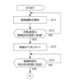
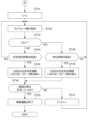
- 5 is a flowchart showing a specific procedure of the warm-up process according to the embodiment (part 1).
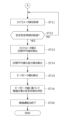
- 6 is a flowchart showing a specific procedure of the warm-up process according to the embodiment (part 2).
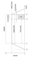
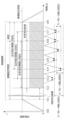
- 4 is a time chart for explaining a procedure of a warm-up process.
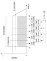
- 11 is a time chart for explaining a procedure of a stable state determination process.
- 10 is a flowchart showing a specific procedure of a warm-up process according to a second embodiment of the present invention (part 1).
- 6 is a flowchart showing a specific procedure of the warm-up process according to the embodiment (part 2).
- 4 is a time chart for explaining a procedure of a warm-up process.
- FIG. 1 is a diagram showing the configuration of a chassis dynamometer system S to which a warm-up method according to this embodiment is applied, and a test vehicle V (hereinafter simply referred to as "vehicle V").
- the vehicle V is described as a four-wheel drive (4WD) vehicle that transmits its power separately to the front wheels Wf and rear wheels Wr, but the present invention is not limited to this.
- the vehicle V may be a front-wheel drive (FWD) vehicle or a rear-wheel drive (RWD) vehicle.
- FWD front-wheel drive
- RWD rear-wheel drive
- the vehicle V is described as being warmed up while placed on rollers 1f, 1r (described below) as shown in FIG. 1, but the present invention is not limited to this.
- the present invention can also be applied to a case where the vehicle V is not placed on rollers 1f, 1r and the vehicle is warmed up using the chassis dynamometer system S alone.
- the chassis dynamometer system S is equipped with front wheel rollers 1f and rear wheel rollers 1r on which the front wheels Wf and rear wheels Wr of the vehicle V can be placed, which rotate according to the rotation of the wheels, a front wheel dynamometer 2f and a rear wheel dynamometer 2r coaxially connected to the rollers 1f and 1r, a front wheel speed sensor 3f and a rear wheel speed sensor 3r that detect the rotational speed of the dynamometers 2f and 2r or the rollers 1f and 1r, respectively, a front wheel torque sensor 4f and a rear wheel torque sensor 4r that detect the torque acting on the dynamometers 2f and 2r, respectively, a front wheel inverter 5f and a rear wheel inverter 5r that supply power to the dynamometers 2f and 2r, respectively, a control device 6 that controls the dynamometers 2f and 2r by operating the inverters 5f and 5r, and an operation measurement system 7 connected to the control device 6.
- the control device 6 performs speed control, running resistance control, automatic warm-up control, etc. of the dynamometers 2f, 2r based on detection signals transmitted from the speed sensors 3f, 3r and torque sensors 4f, 4r, etc., and command signals transmitted from the operation measurement system 7 described below.
- the control device 6 performs a warm-up operation by supplying power to the dynamometers 2f, 2r, which continues to rotate the dynamometers 2f, 2r for a predetermined time so that the rotation speed of the rollers 1f, 1r or the dynamometers 2f, 2r is maintained at a predetermined warm-up setting speed.
- control device 6 operates the inverters 5f, 5r so that the rotation speed detected by the speed sensors 3f, 3r is maintained at the warm-up setting speed, and supplies power to the dynamometers 2f, 2r.
- This warm-up operation can also be performed by having a driver (human or robot) operate the vehicle V placed on the rollers 1f, 1r and transmitting driving force from the wheels Wf, Wr to the rollers 1f, 1r.
- the driver operates the accelerator pedal of the vehicle V so that the vehicle speed of the vehicle V is maintained at a warm-up set speed corresponding to the warm-up set speed.
- the warm-up operation is performed with the wheels Wf, Wr of the vehicle V placed on the rollers 1f, 1r.
- the dynamometers 2f, 2r and rollers 1f, 1r are treated as warm-up targets, and these warm-up targets can be warmed up.
- the warm-up operation of the warm-up target can be performed by the control device 6 supplying power to the dynamometers 2f, 2r, or by the driver operating the vehicle V.
- the operation measurement system 7 is a computer equipped with an operation reception function that receives various operations by the operator of the chassis dynamometer system S, a communication function that transmits and receives various information to the control device 6, a calculation function that performs calculations based on information obtained by the operation reception function, communication function, etc., and a display function that displays the information obtained by the calculation function, communication function, etc. in a manner that can be recognized by the operator.
- FIGS. 2A and 2B are flowcharts showing the specific steps of the warm-up process performed by the operation measurement system 7.
- the warm-up process shown in FIGS. 2A and 2B is repeatedly executed at predetermined control intervals in response to the operation measurement system 7 accepting a warm-up start operation from the operator.
- FIG. 3 is a time chart for explaining the procedure for the warm-up process.
- the specific procedure for the warm-up process shown in FIG. 2A and FIG. 2B will be explained with reference to the time chart in FIG. 3.
- step ST1 the operation measurement system 7 starts the warm-up operation of the warm-up target, and then proceeds to step ST2. More specifically, when the warm-up operation is mainly performed by the control device 6 as described above, the operation measurement system 7 sends a signal to the control device 6 to command the execution of automatic warm-up control. Furthermore, when the warm-up operation is mainly performed by the driver of the vehicle V as described above, the operation measurement system 7 prompts the driver to start the warm-up operation by turning on a lamp indicating the start of the warm-up operation. This causes the rotation speeds of the dynamometers 2f, 2r to start increasing, as shown at time t0 in Figure 3.
- step ST2 the operation measurement system 7 determines whether the rotation speed detected by the speed sensors 3f, 3r has reached a predetermined warm-up setting speed (see FIG. 3). If the determination result in step ST2 is NO, the operation measurement system 7 returns to step ST1, and if the determination result is YES, the operation measurement system 7 proceeds to step ST3.
- step ST3 in response to the rotation speed reaching the warm-up set speed (see time t1 in FIG. 3), the operation measurement system 7 starts a warm-up timer that measures the warm-up time equivalent to the execution time of the warm-up operation, and proceeds to step ST4.
- the operation measurement system 7 continues the warm-up operation until the warm-up time reaches a predetermined warm-up set time (see FIG. 3).
- the warm-up set time can be arbitrarily set by the operator within a predetermined range, for example, based on the operation of the operation measurement system 7 by the operator. Note that hereinafter, the period during which the warm-up operation is being performed, as shown in FIG. 3, is also referred to as the "warm-up period".
- step ST4 the operation measurement system 7 judges whether the warm-up time measured by the warm-up timer has reached a predetermined judgment waiting time (see FIG. 3).
- FIG. 4 is a time chart for explaining the procedure of the stable state determination process.
- the operation measurement system 7 acquires force parameter values correlated with the forces acting on the rollers 1f, 1r or the dynamometers 2f, 2r, stores the acquired force parameter values in a storage medium (not shown), and proceeds to step ST12. More specifically, the operation measurement system 7 acquires detection values of the speed sensors 3f, 3r and detection values of the torque sensors 4f, 4r from the control device 6, and calculates, as force parameter values, driving force values transmitted from both wheels Wf, Wr of the vehicle V to the rollers 1f, 1r by using these detection values.
- Such driving force values can be calculated in the operation measurement system 7 by performing a calculation using a mechanical system model constituted by the rollers 1f, 1r on which the vehicle V is placed and the dynamometers 2f, 2r connected to these rollers 1f, 1r.
- the present invention is not limited to this.
- Any parameter that correlates with the force acting on the rollers 1f, 1r or the dynamometers 2f, 2r may be used as the force parameter.
- the torque detected by the torque sensors 4f, 4r may be used as the force parameter.
- step ST12 the operation measurement system 7 judges whether a predetermined stability judgment time (see FIG. 4) has elapsed from the time when the stable state judgment process was started (see time t2 in FIG. 4) by referring to the warm-up time measured by the warm-up timer.
- the stability judgment time can be arbitrarily set by the operator within a range of a time sufficiently longer than the control period and shorter than the warm-up set time. If the judgment result in step ST12 is NO, the operation measurement system 7 returns to step ST11, and if the judgment result is YES, the operation measurement system 7 proceeds to step ST13.
- the operation measurement system 7 repeatedly executes the process shown in step ST11 over the stability judgment time, thereby repeatedly acquiring the force parameter value for each control period while the warm-up operation is being performed, i.e., while the rotation speed is maintained at the warm-up set speed.
- step ST13 the operation measurement system 7 calculates the section average value of the force parameter value for each of the multiple average calculation sections defined within the stable state determination period (see FIG. 4) in response to the lapse of the stable state determination time from the start of the stable state determination process (see time t3 in FIG. 4), and proceeds to step ST14. More specifically, the operation measurement system 7 defines n (n is an integer of 3 or more) equally spaced average calculation sections within the stable state determination period, and calculates the section average value of the force parameter value for each of the n average calculation sections. Note that, for ease of understanding, FIG. 4 shows a case where five average calculation sections are defined within the stable state determination period.
- the section average value in the i-th (i is an integer from 1 to n) average calculation section is calculated by dividing the sum of the force parameter values included in the n-th average calculation section by the number of force parameter values included in the n-th average calculation section.
- step ST14 the operation measurement system 7 calculates the difference between the section average values in two adjacent average calculation sections (see FIG. 4), and proceeds to step ST15.
- the difference between the section average values in the i-th and i-1-th average calculation sections is calculated by subtracting the section average value in the i-1-th average calculation section from the section average value in the i-th average calculation section.
- step ST15 the operation measurement system 7 calculates the peak-peak value of the n-1 difference values during the stable judgment period (see FIG. 4), and proceeds to step ST16. More specifically, the operation measurement system 7 extracts the maximum and minimum values from the n-1 difference values calculated in step ST14, and calculates the peak-peak value by subtracting the minimum value from the maximum value.
- the peak-peak value calculated by the above procedure increases or decreases depending on the degree of variation in the multiple force parameter values during the stable judgment period, the section average values of the force parameter values for each average calculation section, and the difference values between the section average values in two adjacent average calculation sections. In other words, the greater the variation in these force parameter values, section average values, and difference values, the greater the peak-peak value, and the smaller the variation, the smaller the peak-peak value.
- step ST16 the operation measurement system 7 judges the stable state of the warm-up target including at least the dynamometers 2f and 2r based on the peak-to-peak value calculated in step ST15, and proceeds to step ST20. More specifically, if the peak-to-peak value is equal to or less than a predetermined judgment setting value, the operation measurement system 7 judges that the warm-up target is stable (i.e., sufficiently warmed up), and proceeds to step ST20. If the peak-to-peak value is greater than the judgment setting value, the operation measurement system 7 judges that the warm-up target is not stable, and proceeds to step ST20.
- the operation measurement system 7 preferably stores information on the judgment result in step ST16 in a storage medium (not shown) or displays it in a manner that is visible to the operator. This allows the operator to easily judge whether to start a test using the warm-up target that has already been warmed up, or to execute the warm-up process shown in Figures 2A and 2B again to further warm up the warm-up target, by referring to the judgment result in step ST16.
- the operation measurement system 7 determines the stable state of the warm-up target based on the peak-peak value, but the present invention is not limited to this.
- the operation measurement system 7 may, for example, statistically evaluate the magnitude of variation of the multiple section average values calculated in step ST13, and determine the stable state of the warm-up target based on the evaluation result.
- the operation measurement system 7 may also, for example, statistically evaluate the magnitude of variation of the multiple difference values calculated in step ST14, and determine the stable state of the warm-up target based on the evaluation result.
- step ST20 the operation measurement system 7 ends the warm-up operation started in step ST1 in response to the elapse of the warm-up set time from the start of the warm-up operation (see time t3 in Figures 3 and 4), and ends the warm-up process shown in Figures 2A and 2B. More specifically, if the warm-up operation is being performed mainly by the control device 6, the operation measurement system 7 sends a signal to the control device 6 instructing it to end the automatic warm-up control. Also, if the warm-up operation is being performed mainly by the driver of the vehicle V, the operation measurement system 7 prompts the driver to end the warm-up operation, for example by turning on a lamp indicating the end of the warm-up operation. This causes the rotation speeds of the dynamometers 2f, 2r to begin to decrease, as shown at time t3 in Figure 3.
- the force parameter acquisition device that acquires the force parameter value that is correlated with the torque or force acting on the rollers 1f, 1r or the dynamometers 2f, 2r is composed of the speed sensors 3f, 3r, the torque sensors 4f, 4r, and the operation measurement system 7.
- the stable state determination device that determines the stable state of the warm-up target is composed of the operation measurement system 7.
- the chassis dynamometer system S and the warm-up method according to this embodiment provide the following advantages.
- the warm-up method according to the present embodiment includes a step of performing a warm-up operation for a warm-up period in which the dynamometers 2f, 2r are rotated so that the rotation speed of the rollers 1f, 1r or the dynamometers 2f, 2r is maintained at a warm-up set speed.
- the warm-up operation is performed under such a constant rotation speed, the warm-up of the warm-up object including at least the dynamometers 2f, 2r gradually progresses, and the variation in the force parameter value also gradually decreases.
- the force parameter value in a stability determination period set within the warm-up period is obtained, an interval average value of the force parameter value is calculated for each of a plurality of average calculation intervals set within this stability determination period, and the stable state of the warm-up object is determined based on the magnitude of the variation of the plurality of interval average values within the stability determination period.
- the stable state of the warm-up object can be accurately determined taking into account the internal state of the dynamometers 2f, 2r.
- the instantaneous value of the force parameter value still has a certain degree of variation due to various factors.
- the stable state of the warm-up target can be determined with greater accuracy by using the section average value of the force parameter values for each of a plurality of average calculation sections defined within the stability determination period. Therefore, according to this embodiment, the warm-up target can be warmed up for an appropriate period of time.
- the warm-up operation is performed with the wheels Wf, Wr of the vehicle V placed on the rollers 1f, 1r.
- the dynamometers 2f, 2r and rollers 1f, 1r not only the dynamometers 2f, 2r and rollers 1f, 1r but also the wheels Wf, Wr of the vehicle V in contact with the rollers 1f, 1r rotate. Therefore, according to this embodiment, the dynamometers 2f, 2r, rollers 1f, 1r, and the vehicle V are treated as warm-up targets, and these warm-up targets can be warmed up. Therefore, according to this embodiment, after the warm-up operation is performed, testing of the vehicle V can be continued using the warmed-up dynamometer system S.
- the stable state of the warm-up target is determined based on the magnitude of variation in the difference value of the section average values in two adjacent average calculation sections. This makes it possible to more accurately determine the stable state of the warm-up target while eliminating the influence of the variation in instantaneous values as described above, and ultimately to warm up the warm-up target for an appropriate period of time.
- the warm-up target is determined to be stable, and if the peak-to-peak value is greater than the determination set value, the warm-up target is determined to be unstable. This makes it possible to more accurately determine the stable state of the warm-up target while eliminating the effects of the instantaneous value variations described above, and ultimately to warm up the warm-up target for an appropriate period of time.
- the control device 6 operates the inverters 5f, 5r and supplies power to the dynamometers 2f, 2r to rotate the dynamometers 2f, 2r. This allows the operator to automatically perform warm-up operation using the control device 6 without operating the vehicle V, which is highly convenient.
- the dynamometers 2f, 2r are rotated by transmitting driving force from the vehicle V to the rollers 1f, 1r.
- the operation measurement system 7 of the chassis dynamometer system S of this embodiment acquires the values of the force parameters over a predetermined judgment period while the rotational speed of the rollers 1f, 1r or the dynamometers 2f, 2r is maintained at the warm-up set speed, i.e., while the warm-up operation as described above is being performed, calculates the section average value of the force parameter values for each of a plurality of average calculation sections defined in this stability judgment period, and further judges the stable state of the warm-up object including at least the dynamometers 2f, 2r based on the magnitude of variation of the plurality of section average values within this stability judgment period.
- the stable state of the dynamometers 2f, 2r can be accurately determined taking into account the internal state of the dynamometers 2f, 2r, and thus the warm-up object can be warmed up for an appropriate period of time.
- the chassis dynamometer system according to this embodiment differs from the chassis dynamometer system S according to the first embodiment in the warm-up process procedure in the operation measurement system 7. More specifically, in the warm-up process according to the first embodiment, the length of the warm-up period during which the warm-up operation is performed is fixed to the warm-up set time set by the operator, regardless of the determination result of the stable state determination process. In contrast, in the warm-up process according to this embodiment, as described below, the length of the warm-up period is extended from the warm-up set time set by the operator depending on the determination result of the stable state determination process.
- FIGS. 5A and 5B are flowcharts showing the specific steps of the warm-up process performed by the operation measurement system 7 according to this embodiment.
- the warm-up process shown in FIG. 5A and FIG. 5B is repeatedly executed at predetermined control intervals in response to the operation measurement system 7 accepting a warm-up start operation by the operator.
- FIG. 6 is a time chart for explaining the procedure for the warm-up process.
- the specific procedure for the warm-up process shown in FIG. 5A and FIG. 5B will be explained with reference to the time chart in FIG. 6.
- step ST31 the operation measurement system 7 starts the warm-up operation of the dynamometer using the same procedure as in step ST1 (see FIG. 2A), and then proceeds to step ST32.
- the rotation speed of the dynamometer starts to increase, as shown at time t10 in FIG. 6.
- step ST32 the operation measurement system 7 determines whether or not the rotation speed detected by the speed sensor has reached a predetermined warm-up setting speed (see FIG. 6) using the same procedure as in step ST2 (see FIG. 2A). If the determination result in step ST32 is NO, the operation measurement system 7 returns to step ST31, and if the determination result is YES, the operation measurement system 7 proceeds to step ST33.
- step ST33 in response to the rotation speed reaching the warm-up set speed (see time t11 in FIG. 6), the operation measurement system 7 starts a warm-up timer that measures a warm-up time equivalent to the execution time of the warm-up operation in the same procedure as step ST3 (see FIG. 2A), and proceeds to step ST34.
- the operation measurement system 7 unlike the warm-up process according to the first embodiment, the operation measurement system 7 according to this embodiment continues the warm-up operation as necessary after the warm-up time reaches a predetermined warm-up set time (see FIG. 6).
- the warm-up set time can be arbitrarily set by the operator within a predetermined range, for example, based on the operation of the operation measurement system 7 by the operator, as in the warm-up process according to the first embodiment.
- the period during which the warm-up operation is being performed is also referred to as the "warm-up period", as in the first embodiment.
- step ST34 the operation measurement system 7 judges whether the warm-up time measured by the warm-up timer described above has reached a predetermined judgment waiting time (see FIG. 6) by the same procedure as in step ST4 (see FIG. 2A).
- step ST34 the period during which the operation measurement system 7 executes the stable state judgment process consisting of steps ST41 to ST46 is also referred to as the "stable judgment period" as in the first embodiment. If the judgment result in step ST34 is NO, the operation measurement system 7 returns to step ST34 to wait for the execution of the stable state judgment process while executing the warm-up operation.
- step ST41 the operation measurement system 7 sets the counter value C for counting the number of times the stable state determination process is executed to "1" in response to the warm-up time reaching the determination wait time (see time t12 in FIG. 6), and proceeds to step ST42.
- step ST42 the operation measurement system 7 acquires the force parameter values using the same procedure as in step ST11 (see FIG. 2B), stores the acquired force parameter values in a storage medium (not shown), and proceeds to step ST43.
- step ST43 the operation measurement system 7 determines whether the counter value C is equal to or greater than "2". If the determination result in step ST43 is NO, that is, if the first stable state determination process is being executed, the operation measurement system 7 proceeds to step ST44.
- step ST44 the operation measurement system 7 judges whether or not a predetermined stability judgment time (see FIG. 6) has elapsed since the time when the first stable state judgment process was started (see time t12 in FIG. 6), i.e., the time when the counter value C was set to "1" in step ST41, by referring to the warm-up time measured by the warm-up timer.
- the stability judgment time can be arbitrarily set by the operator within a range sufficiently longer than the control period and shorter than the warm-up set time, as in the first embodiment. If the judgment result in step ST44 is NO, the operation measurement system 7 returns to step ST42, and if the judgment result is YES, the operation measurement system 7 proceeds to step ST45.
- the operation measurement system 7 repeatedly executes the process shown in step ST42 over the stability judgment time, thereby repeatedly acquiring the force parameter value for each control period while the warm-up operation is being performed, i.e., while the rotation speed is maintained at the warm-up set speed.
- step ST45 the operation measurement system 7 calculates the peak-to-peak values in the first stability determination period (times t12 to t16 in FIG. 6) in the same manner as in steps ST13 to ST15 (see FIG. 2B) based on the multiple force parameter values included in the first stability determination period (times t12 to t16 in FIG. 6) (see FIG. 6), and proceeds to step ST46. More specifically, the operation measurement system 7 calculates the section average value of the force parameter values for each of the multiple average calculation sections defined in the first stability determination period (see step ST13 in FIG. 2B), calculates the difference value of the section average values in two adjacent average calculation sections in the first stability determination period (see step ST14 in FIG. 2B), and further calculates the peak-to-peak values of n-1 difference values in the first stability determination period (see step ST15 in FIG. 2B).
- step ST46 the operation measurement system 7 determines whether the warm-up target is stable based on the peak-to-peak value calculated in step ST45 or step ST49 described below. More specifically, the operation measurement system 7 determines whether the warm-up target is stable or not by comparing the peak-to-peak value calculated in step ST45 or step ST49 described below with a predetermined determination set value. Here, if the peak-to-peak value is equal to or less than the determination threshold, the operation measurement system 7 determines that the warm-up target is stable and proceeds to step ST50. On the other hand, if the peak-to-peak value is greater than the determination threshold, the operation measurement system 7 determines that the warm-up target is not yet sufficiently stable and proceeds to step ST47.
- step ST50 the operation measurement system 7 performs the warm-up operation over the warm-up period, and upon determining that the warm-up target is stable, ends the warm-up operation started in step ST31 by a procedure similar to that of step ST20 (see FIG. 2B), and ends the warm-up process shown in FIG. 5A and FIG. 5B.
- step ST43 If the result of the determination in step ST43 is YES, i.e., the second or subsequent stable state determination process is being executed, the process proceeds to step ST48.
- step ST48 the operation measurement system 7 refers to the warm-up time measured by the warm-up timer to determine whether or not a predetermined unit time has elapsed since the time when the Cth stable state determination process was started, i.e., the time when the counter value C was counted up in step ST47.
- the unit time is set to a time shorter than the stable state determination time, for example, the same time as the length of the average calculation interval. If the determination result in step ST48 is NO, the operation measurement system 7 returns to step ST42, and if the determination result is YES, it proceeds to step ST49.
- step ST46 determines in the processing of step ST46 that the warm-up target is stable (i.e., if the determination result of step ST46 is NO)
- it counts up the counter value C (see step ST47)
- step ST49 the operation measurement system 7 calculates the peak-to-peak value in the Cth stable judgment period using the same procedure as in step ST45 based on the multiple force parameter values included in the Cth stable judgment period, and proceeds to step ST46.
- the Cth stable judgment period is defined by shifting both the start (time t12 in the example of FIG. 6) and end (time t16 in the example of FIG. 6) of the first stable judgment period by unit time ⁇ C toward the later side, as shown in FIG. 6.
- the start and end of the second stable judgment period will be time t13 and time t17, and the start and end of the third stable judgment period will be time t14 and time t18 (see FIG. 6).
- the operation measurement system 7 when the operation measurement system 7 extends the warm-up period by executing the processing of step ST47, it repeatedly determines the stable state of the warm-up target by changing the start and end of the stability determination period by unit time toward the later side until it is determined that the warm-up target is stable in the processing of step ST46.
- the longer the warm-up operation is performed the more the warm-up of the warm-up target is promoted, so the variation in the force parameter values becomes smaller, and the peak-to-peak value also becomes smaller.
- the chassis dynamometer system and warm-up method according to this embodiment provide the following advantages in addition to the advantages (1) to (7) described above.
- the warm-up period is extended and the warm-up operation is continued.
- the warm-up operation is automatically continued without the operation of the operator, and the warm-up target can be further warmed up.
- the warm-up period when the warm-up period is extended as described above, the start and end of the stability determination period are changed toward the later side by a predetermined unit time in increments of time until it is determined that the warm-up target is stable, and the stable state of the warm-up target is repeatedly determined. Therefore, according to this embodiment, the warm-up period can be automatically optimized without the need for operator operation.
- the present invention is not limited to these.
- the detailed configuration may be modified as appropriate within the scope of the spirit of the present invention.
- the warm-up operation may be performed by the chassis dynamometer system S alone, without placing the vehicle V on the rollers 1f, 1r.
- V Vehicle (test vehicle, to be warmed up)
- Wf Front wheel (wheel) Wr...Rear wheel (wheel)
- S...Chassis dynamometer system dynamometer system 1f, 1r...Roller (warm-up target) 2f, 2r...Dynamometer (for warming up) 3f, 3r...Speed sensor 4f, 4r...Torque sensor 5f, 5r...Front wheel inverter 6...Control device 7...Operation measurement system
Landscapes
- Physics & Mathematics (AREA)
- General Physics & Mathematics (AREA)
- Testing Of Engines (AREA)
Abstract
シャシダイナモメータシステムの暖機方法は、ローラ又はダイナモメータの回転速度が所定の暖機設定速度に維持されるようにダイナモメータを回転させる暖機運転を所定の暖機期間にわたり実行する工程と、暖機期間内に定められた安定判定期間における、ローラ又はダイナモメータに作用する力と相関のある力パラメータ値を取得する工程と、安定判定期間内に定められた複数の平均算出区間ごとに力パラメータ値の区間平均値を算出する工程と、隣接する2つの平均算出区間における区間平均値の差分値を算出する工程と、安定判定期間内における差分値のピークピーク値を算出する工程と、ピークピーク値に基づいて少なくともダイナモメータを含む暖機対象の安定状態を判定する工程と、を備える。
Description
本発明は、ダイナモメータシステム及びその暖機方法に関する。より詳しくは、試験毎のばらつきの少ない高精度な結果が得られるように、適切な時間にわたりダイナモメータを暖機できるダイナモメータシステム及びその暖機方法に関する。
耐久試験、排気浄化性能評価試験、及び燃費計測試験等の車両試験では、シャシダイナモメータシステムが用いられる。シャシダイナモメータシステムは、試験対象となる車両の車輪が載置されるローラとこのローラに連結されたダイナモメータとを備え、ローラ上で走行する車両に対してころがり抵抗や慣性抵抗等の実走行時に発生する走行抵抗をダイナモメータ及びローラを用いて与えることにより、実走行条件に近い条件を再現する。
このようなシャシダイナモメータシステムを用いて高精度な試験を行うためには、ダイナモメータやローラ等の機械部品は、試験を開始する前に十分に暖機しておく必要がある。例えば特許文献1に示されたシャシダイナモメータシステムでは、ローラ上に載置された車両を駆動し、車両の駆動力を利用してダイナモメータを回転させることによって車両と共にダイナモメータを暖機している。ここで特許文献1に示されたシャシダイナモメータでは、ローラ表面又はタイヤ表面の少なくとも一方の温度を温度センサで測定することによって、上述のような暖機運転によってローラとタイヤの間が十分に暖機されたかどうかを判定している。
しかしながら温度センサでは、ローラや車輪の表面の温度しか測定することができない。このため、機械部品の内部まで十分に暖機されたかどうかを適切に判定することができない。またシャシダイナモメータシステムの暖機は、車両をローラの上に載置せず、ダイナモメータ単体で行う場合もあるが、このような場合、特許文献1の技術ではダイナモメータが十分に暖機されたかどうかを適切に判定することができない。このため、特許文献1の技術では適切な暖機時間が分からず、結果として十分に暖機できない場合や、必要以上に暖機してしまう場合がある。
本発明は、適切な時間にわたりダイナモメータを暖機できるダイナモメータシステム及びその暖機方法を提供することを目的とする。
(1)本発明は、車両(例えば、後述の車両V)の車輪(例えば、後述の前輪Wf及び後輪Wr)が載置可能なローラ(例えば、後述のローラ1f,1r)と、当該ローラと連結されたダイナモメータ(例えば、後述のダイナモメータ2f,2r)と、前記ローラ又は前記ダイナモメータに作用する力と相関のある力パラメータ値を取得する力パラメータ取得装置(例えば、後述の速度センサ3f,3r、トルクセンサ4f,4r、及び操作計測システム7)と、を備えるダイナモメータシステムの暖機方法に関する。この暖機方法は、前記ローラ又は前記ダイナモメータの回転速度が所定の設定速度(例えば、後述の暖機設定速度)に維持されるように前記ダイナモメータを回転させる暖機運転を所定の暖機期間にわたり実行する工程と、前記暖機期間内に定められた判定期間における前記力パラメータ値を取得する工程と、前記判定期間内に定められた複数の平均算出区間ごとに前記力パラメータ値の区間平均値を算出する工程と、前記判定期間内における複数の前記区間平均値のばらつきの大きさに基づいて前記ダイナモメータを含む暖機対象の安定状態を判定する工程と、を備えることを特徴とする。
(2)この場合、前記暖機運転は、試験車両の車輪を前記ローラに載置した状態で行うことが好ましい。
(3)この場合、隣接する2つの前記平均算出区間における前記区間平均値の差分値のばらつきの大きさに基づいて前記安定状態を判定することが好ましい。
(4)この場合、前記判定期間内における前記差分値のピークピーク値が所定の判定設定値以下である場合、前記暖機対象は安定していると判定し、前記ピークピーク値が前記判定設定値より大きい場合、前記暖機対象は安定していないと判定することが好ましい。
(5)この場合、前記暖機期間が経過するまでの間に前記暖機対象は安定していると判定されなかった場合、前記暖機期間を延長し前記暖機運転を継続することが好ましい。
(6)この場合、前記暖機期間を延長した場合、前記暖機対象は安定していると判定されるまで、前記判定期間の始期及び終期を所定の単位時間ずつ後期側へ変更しながら繰り返し前記安定状態を判定することが好ましい。
(7)この場合、前記暖機運転では、前記ダイナモメータの制御装置が前記ダイナモメータに電力を供給することによって前記ダイナモメータを回転させることが好ましい。
(8)この場合、前記暖機運転では、前記試験車両から前記ローラに駆動力を伝達することによって前記ダイナモメータを回転させることが好ましい。
(9)本発明に係るダイナモメータシステム(例えば、後述のシャシダイナモメータシステムS)は、車両の車輪が載置可能なローラ(例えば、後述のローラ1f,1r)と、当該ローラと連結されたダイナモメータ(例えば、後述のダイナモメータ2f,2r)と、前記ローラ又は前記ダイナモメータに作用する力と相関のある力パラメータ値を取得する力パラメータ取得装置(例えば、後述の速度センサ3f,3r、トルクセンサ4f,4r、及び操作計測システム7)、前記ダイナモメータを含む暖機対象の安定状態を判定する安定状態判定装置(例えば、後述の操作計測システム7)と、を備え、前記安定状態判定装置は、前記ローラ又は前記ダイナモメータの回転速度が所定の設定速度に維持されている間に、所定の判定期間にわたり前記力パラメータ値を取得し、前記判定期間に定められた複数の平均算出区間ごとに前記力パラメータ値の区間平均値を算出し、前記判定期間内における複数の前記区間平均値のばらつきの大きさに基づいて前記暖機対象の安定状態を判定することを特徴とする。
(1)本発明に係る暖機方法は、ローラ又はダイナモメータの回転速度が設定速度に維持されるようにダイナモメータを回転させる暖機運転を暖機期間にわたり実行する工程を備える。このような一定の回転速度の下での暖機運転を実行すると、少なくともダイナモメータを含む暖機対象の暖機が徐々に進行し、ひいては力パラメータ値のばらつきも徐々に小さくなる。そこで本発明では、暖機期間内に定められた判定期間における力パラメータ値を取得し、この判定期間内に定められた複数の平均算出区間ごとに力パラメータ値の区間平均値を算出し、判定期間内における複数の区間平均値のばらつきの大きさに基づいて暖機対象の安定状態を判定する。このように本発明では、ダイナモメータの内部の状態を反映した力パラメータ値を用いることにより、ダイナモメータの内部の状態を考慮して暖機対象の安定状態を精度良く判定することができる。また力パラメータ値の瞬時値は、暖機が十分に進行した状態であっても、様々な要因によってある程度のばらつきが残ってしまう。特にローラに載置された車両を駆動することによって回転速度を設定速度に維持している場合、車両特性やドライバによる操作等の影響によって瞬時値のばらつきが大きくなる傾向がある。これに対し本発明では、判定期間内に定められた複数の平均算出区間ごとの力パラメータ値の区間平均値を用いることにより、暖機対象の安定状態をさらに精度良く判定することができる。よって本発明によれば、適切な時間にわたり暖機対象を暖機することができる。
(2)本発明では、試験車両の車輪をローラに載置した状態で暖機運転を行う。これにより暖機運転を行っている間、ダイナモメータ及びローラだけでなく、ローラに接する試験車両の車輪も回転する。よって本発明によれば、ダイナモメータ、ローラ、及び試験車両を暖機対象とし、これら暖機対象を暖機することができる。よって本発明によれば、暖機運転を行った後は、引き続き暖機後のダイナモメータシステムを用いて試験車両に対する試験を行うことができる。
(3)本発明では、隣接する2つの平均算出区間における区間平均値の差分値のばらつきの大きさに基づいて暖機対象の安定状態を判定する。これにより、上述のような瞬時値のばらつきの影響を除きつつ、暖機対象の安定状態をさらに精度良く判定することができ、ひいては適切な時間にわたり暖機対象を暖機することができる。
(4)本発明では、判定期間内における差分値のピークピーク値が判定設定値以下である場合、暖機対象は安定していると判定し、ピークピーク値が判定設定値より大きい場合、暖機対象は安定していないと判定する。これにより、上述のような瞬時値のばらつきの影響を除きつつ、暖機対象の安定状態をさらに精度良く判定することができ、ひいては適切な時間にわたり暖機対象を暖機することができる。
(5)本発明では、暖機期間が経過するまでの間に暖機対象は安定していると判定されなかった場合、この暖機期間を延長し、暖機運転を継続する。よって本発明によれば、当初予定していた暖機期間にわたる暖機運転では暖機対象を十分に暖機できなかった場合、オペレータの操作によらず自動で暖機運転を継続し、暖機対象をさらに暖機することができる。
(6)本発明では、上述のように暖機期間を延長した場合、暖機対象は安定していると判定されるまで、判定期間の始期及び終期を所定の単位時間ずつ後期側へ変更しながら繰り返し安定状態を判定する。よって本発明によれば、オペレータの操作によらずに暖機期間を自動で最適化することができる。
(7)本発明において、暖機運転では、ダイナモメータの制御装置がダイナモメータに電力を供給することによってダイナモメータを回転させる。これによりオペレータは、試験車両を操作することなく、制御装置を用いて自動で暖機運転を行うことができるので、利便性が高い。
(8)また本発明において、暖機運転では、試験車両からローラに駆動力を伝達することによってダイナモメータを回転させてもよい。これにより、暖機運転を行うためにはドライバ(人又はロボット)が試験車両を操作する必要があるものの、試験車両の暖機を促進できるので、利便性が高い。
(9)本発明に係るダイナモメータシステムの安定状態判定装置は、ローラ又はダイナモメータの回転速度が設定速度に維持されている間、すなわち上述のような暖機運転が実行されている間に、所定の判定期間にわたり力パラメータの値を取得し、この判定期間に定められた複数の平均算出区間ごとに力パラメータ値の区間平均値を算出し、さらにこの判定期間内における複数の区間平均値のばらつきの大きさに基づいて少なくともダイナモメータを含む暖機対象の安定状態を判定する。よって本発明によれば、(1)の発明と同じ理由により、ダイナモメータの内部の状態を考慮して暖機対象の安定状態を精度良く判定することができ、ひいては適切な時間にわたり暖機対象を暖機することができる。
<第1実施形態>
以下、本発明の第1実施形態について、図面を参照しながら説明する。
図1は、本実施形態に係る暖機方法が適用されたシャシダイナモメータシステムS及びその試験車両V(以下、単に「車両V」という)の構成を示す図である。
以下、本発明の第1実施形態について、図面を参照しながら説明する。
図1は、本実施形態に係る暖機方法が適用されたシャシダイナモメータシステムS及びその試験車両V(以下、単に「車両V」という)の構成を示す図である。
以下では、車両Vは、その動力を前輪Wf及び後輪Wrへ分離して伝達する四輪駆動(4WD)車両とした場合について説明するが、本発明はこれに限らない。車両Vは、前輪駆動(FWD)車両や後輪駆動(RWD)車両としてもよい。また以下では、図1に示すように車両Vを後述のローラ1f,1rに載置した状態で暖機運転を行う場合について説明するが、本発明はこれに限らない。本発明は、車両Vをローラ1f,1rに載置せず、シャシダイナモメータシステムS単体で暖機運転を行う場合も適用できる。
シャシダイナモメータシステムSは、車両Vの前輪Wf及び後輪Wrがそれぞれ載置可能であり、各々の回転に従って回転する前輪ローラ1f及び後輪ローラ1rと、これらローラ1f,1rにそれぞれ同軸で連結された前輪ダイナモメータ2f及び後輪ダイナモメータ2rと、ダイナモメータ2f,2r又はローラ1f,1rの回転速度をそれぞれ検出する前輪速度センサ3f及び後輪速度センサ3rと、ダイナモメータ2f,2rに作用するトルクをそれぞれ検出する前輪トルクセンサ4f及び後輪トルクセンサ4rと、ダイナモメータ2f,2rのそれぞれに電力を供給する前輪インバータ5f及び後輪インバータ5rと、これらインバータ5f,5rを操作することによってダイナモメータ2f,2rを制御する制御装置6と、この制御装置6に接続された操作計測システム7と、を備える。
制御装置6は、速度センサ3f,3r及びトルクセンサ4f,4r等から送信される検出信号や後述の操作計測システム7から送信される指令信号等に基づいて、ダイナモメータ2f,2rの速度制御、走行抵抗制御、及び自動暖機制御等を行う。制御装置6は、特に自動暖機制御では、ローラ1f,1r又はダイナモメータ2f,2rの回転速度が所定の暖機設定速度に維持されるようにダイナモメータ2f,2rを所定時間にわたり回転させ続ける暖機運転を、ダイナモメータ2f,2rに電力を供給することによって実行する。より具体的には、制御装置6は、自動暖機制御では、速度センサ3f,3rによって検出される回転速度が暖機設定速度に維持されるようにインバータ5f,5rを操作し、ダイナモメータ2f,2rに電力を供給する。
なおこのような暖機運転は、ローラ1f,1rに載置された車両Vをドライバ(人又はロボット)が操作し、車輪Wf,Wrからローラ1f,1rに駆動力を伝達することによって実行することもできる。この場合、ドライバは、車両Vの車速が暖機設定速度に応じた暖機設定車速で維持されるように車両Vのアクセルペダルを操作する。
上述のように本実施形態では、車両Vの車輪Wf,Wrをローラ1f,1rに載置した状態で暖機運転を行う。これにより、暖機運転を行っている間、ダイナモメータ2f,2r及びローラ1f,1rだけでなく、ローラ1f,1rに接する車両Vの車輪Wf,Wrも回転する。よって本実施形態によれば、ダイナモメータ2f,2r、ローラ1f,1r及び車両Vを暖機対象とし、これら暖機対象を暖機することができる。
以上のように、本実施形態に係るシャシダイナモメータシステムSでは、暖機対象の暖機運転は、制御装置6がダイナモメータ2f,2rに電力を供給することによって実行することもできるし、ドライバが車両Vを操作することによって実行することもできる。
操作計測システム7は、シャシダイナモメータシステムSのオペレータによる各種操作を受け付ける操作受付機能と、制御装置6に対し各種情報を送受信する通信機能と、操作受付機能や通信機能等によって得られた情報に基づいて演算を行う演算機能と、この演算機能や通信機能等によって得られた情報をオペレータが認識可能な態様で表示する表示機能と、を備えるコンピュータである。
図2A及び図2Bは、操作計測システム7による暖機処理の具体的な手順を示すフローチャートである。図2A及び図2Bに示す暖機処理は、操作計測システム7において、オペレータによる暖機開始操作を受け付けたことに応じて、所定の制御周期ごとに繰り返し実行される。
図3は、暖機処理の手順を説明するためのタイムチャートである。以下では、図2A及び図2Bに示す暖機処理の具体的な手順について、図3のタイムチャートを参照しながら説明する。
始めにステップST1では、操作計測システム7は、暖機対象の暖機運転を開始し、ステップST2に移る。より具体的には、操作計測システム7は、上述のように制御装置6を主体として暖機運転を行う場合、制御装置6へ自動暖機制御の実行を指令する信号を送信する。また操作計測システム7は、上述のように車両Vのドライバを主体として暖機運転を行う場合、暖機運転の開始を示すランプを点灯することにより、ドライバに対し暖機運転の開始を促す。これにより、図3において時刻t0に示すように、ダイナモメータ2f、2rの回転速度が上昇し始める。
ステップST2では、操作計測システム7は、速度センサ3f,3rによって検出される回転速度が所定の暖機設定速度(図3参照)に到達したか否かを判定する。操作計測システム7は、ステップST2の判定結果がNOである場合、ステップST1に戻り、YESである場合、ステップST3に移る。
ステップST3では、操作計測システム7は、回転速度が暖機設定速度に到達したことに応じて(図3における時刻t1参照)、暖機運転の実行時間に相当する暖機時間を測定する暖機タイマをスタートし、ステップST4に移る。以下で説明するように、本実施形態に係る操作計測システム7は、暖機時間が所定の暖機設定時間(図3参照)に到達するまで暖機運転を継続する。ここで暖機設定時間は、例えばオペレータによる操作計測システム7の操作に基づいて、所定の範囲内でオペレータが任意に設定可能である。なお以下では、図3に示すように、暖機運転が実行されている期間を「暖機期間」とも言う。
ステップST4では、操作計測システム7は、上述の暖機タイマによって測定される暖機時間は、所定の判定待ち時間(図3参照)に到達したか否かを判定する。ここで判定待ち時間は、図3に示すように暖機設定時間から後述の安定判定時間を減じた時間に設定される(暖機設定時間=判定待ち時間+安定判定時間)。操作計測システム7は、ステップST4の判定結果がYESである場合、以下で説明するダイナモメータ2f,2rの安定状態判定処理を開始するべく、ステップST11に移る。なお以下では、図3に示すように操作計測システム7がステップST11~ST16によって構成される安定状態判定処理を実行する期間を、「安定判定期間」とも言う。また操作計測システム7は、ステップST4の判定結果がNOである場合、暖機運転を実行しながら安定状態判定処理の実行を待機するべく、ステップST4に戻る。
図4は、安定状態判定処理の手順を説明するためのタイムチャートである。
始めにステップST11では、操作計測システム7は、ローラ1f,1r又はダイナモメータ2f,2rに作用する力と相関のある力パラメータ値を取得し、取得した力パラメータ値を図示しない記憶媒体に記憶し、ステップST12に移る。より具体的には、操作計測システム7は、速度センサ3f,3rの検出値及びトルクセンサ4f,4rの検出値を制御装置6から取得し、これら検出値を用いることによって、車両Vの両輪Wf,Wrからローラ1f,1rに伝達する駆動力値を力パラメータ値として算出する。このような駆動力値は、操作計測システム7において、車両Vが載置されるローラ1f,1rと、これらローラ1f,1rと連結されるダイナモメータ2f,2rとによって構成される機械系モデルを用いた演算を行うことによって算出することができる。
始めにステップST11では、操作計測システム7は、ローラ1f,1r又はダイナモメータ2f,2rに作用する力と相関のある力パラメータ値を取得し、取得した力パラメータ値を図示しない記憶媒体に記憶し、ステップST12に移る。より具体的には、操作計測システム7は、速度センサ3f,3rの検出値及びトルクセンサ4f,4rの検出値を制御装置6から取得し、これら検出値を用いることによって、車両Vの両輪Wf,Wrからローラ1f,1rに伝達する駆動力値を力パラメータ値として算出する。このような駆動力値は、操作計測システム7において、車両Vが載置されるローラ1f,1rと、これらローラ1f,1rと連結されるダイナモメータ2f,2rとによって構成される機械系モデルを用いた演算を行うことによって算出することができる。
なお以下では、車両Vからローラ1f,1rに伝達する駆動力を力パラメータとした場合について説明するが、本発明はこれに限らない。力パラメータとしては、ローラ1f,1r又はダイナモメータ2f,2rに作用する力と相関のあるパラメータであればどのようなものでもよい。例えば、トルクセンサ4f,4rによって検出されるトルクを力パラメータとして採用してもよい。
ステップST12では、操作計測システム7は、上記暖機タイマによって測定される暖機時間を参照することにより、安定状態判定処理を開始した時刻(図4における時刻t2参照)から所定の安定判定時間(図4参照)が経過したか否かを判定する。ここで安定判定時間は、制御周期よりも十分に長くかつ暖機設定時間よりも短い時間の範囲内でオペレータが任意に設定可能である。操作計測システム7は、ステップST12の判定結果がNOである場合、ステップST11に戻り、YESである場合、ステップST13に移る。以上のように操作計測システム7は、安定状態判定処理では、安定判定時間にわたりステップST11に示す処理を繰り返し実行することにより、暖機運転が行われている間、すなわち回転速度が暖機設定速度に維持されている間における力パラメータ値を制御周期ごとに繰り返し取得する。
ステップST13では、操作計測システム7は、安定状態判定処理を開始してから安定判定時間が経過したことに応じて(図4の時刻t3参照)、安定判定期間内に定められた複数の平均算出区間ごとに力パラメータ値の区間平均値を算出し(図4参照)、ステップST14に移る。より具体的には、操作計測システム7は、安定判定期間内にn個(nは、3以上の整数)の等間隔の平均算出区間を定義し、n個の平均算出区間ごとに力パラメータ値の区間平均値を算出する。なお図4では、理解を容易にするため、安定判定期間内に5個の平均算出区間を定義した場合を示す。ここで例えばi番目(iは、1からnまでの整数)の平均算出区間における区間平均値は、n番目の平均算出区間に含まれる力パラメータ値の総和を、n番目の平均算出区間に含まれる力パラメータ値の数で除算することによって算出される。
ステップST14では、操作計測システム7は、隣接する2つの平均算出区間における区間平均値の差分値を算出し(図4参照)、ステップST15に移る。ここで例えばi番目とi-1番目の平均算出区間における区間平均値の差分値は、i番目の平均算出区間における区間平均値からi-1番目の平均算出区間における区間平均値を減算することによって算出される。
ステップST15では、操作計測システム7は、安定判定期間内におけるn-1個の差分値のピークピーク値を算出し(図4参照)、ステップST16に移る。より具体的には、操作計測システム7は、ステップST14において算出されたn-1個の差分値の中から最大値及び最小値を抽出し、最大値から最小値を減算することによってピークピーク値を算出する。以上のような手順によって算出されるピークピーク値は、安定判定期間における複数の力パラメータ値、平均算出区間ごとの力パラメータ値の区間平均値、及び隣接する2つの平均算出区間における区間平均値の差分値等のばらつきの大きさに応じて増減する。すなわち、これら力パラメータ値、区間平均値、及び差分値のばらつきが大きくなるほどピークピーク値は大きくなり、ばらつきが小さくなるほどピークピーク値は小さくなる
ステップST16では、操作計測システム7は、ステップST15で算出されたピークピーク値に基づいて、少なくともダイナモメータ2f,2rを含む暖機対象の安定状態を判定し、ステップST20に移る。より具体的には、操作計測システム7は、ピークピーク値が所定の判定設定値以下である場合、暖機対象は安定している(すなわち、十分に暖機されている)と判断し、ステップST20に移る。また操作計測システム7は、ピークピーク値が判定設定値より大きい場合、暖機対象は安定していないと判定し、ステップST20に移る。ここで操作計測システム7は、オペレータが適宜ステップST16における判定結果を参照できるようにするため、ステップST16の判定結果に関する情報を、図示しない記憶媒体に記憶させたり、オペレータが視認可能な態様で表示したりすることが好ましい。これによりオペレータは、ステップST16の判定結果を参照し、暖機済みの暖機対象を用いた試験を開始するか、或いは暖機対象をさらに暖機するために再び図2A及び図2Bに示す暖機処理を実行するかを、容易に判断することができる。
なお本実施形態では、操作計測システム7は、ピークピーク値に基づいて暖機対象の安定状態を判定する場合について説明するが、本発明はこれに限らない。操作計測システム7は、例えばステップST13において算出される複数の区間平均値のばらつきの大きさを統計的に評価し、その評価結果に基づいて暖機対象の安定状態を判定してもよい。また操作計測システム7は、例えばステップST14において算出される複数の差分値のばらつきの大きさを統計的に評価し、その評価結果に基づいて暖機対象の安定状態を判定してもよい。
ステップST20では、操作計測システム7は、暖機運転を開始してから暖機設定時間が経過したことに応じて(図3及び図4における時刻t3参照)、ステップST1で開始した暖機運転を終了し、図2A及び図2Bに示す暖機処理を終了する。より具体的には、操作計測システム7は、制御装置6を主体として暖機運転を行っている場合、制御装置6へ自動暖機制御の終了を指令する信号を送信する。また操作計測システム7は、車両Vのドライバを主体として暖機運転を行っている場合、例えば暖機運転の終了を示すランプを点灯することにより、ドライバに対し暖機運転の終了を促す。これにより図3において時刻t3に示すように、ダイナモメータ2f、2rの回転速度が低下し始める。
以上のように本実施形態では、ローラ1f,1r又はダイナモメータ2f,2rに作用するトルク又は力と相関のある力パラメータ値を取得する力パラメータ取得装置は、速度センサ3f,3rと、トルクセンサ4f,4rと、操作計測システム7と、によって構成される。また暖機対象の安定状態を判定する安定状態判定装置は、操作計測システム7によって構成される。
本実施形態に係るシャシダイナモメータシステムS及び暖機方法によれば、以下の効果を奏する。
(1)本実施形態に係る暖機方法は、ローラ1f,1r又はダイナモメータ2f,2rの回転速度が暖機設定速度に維持されるようにダイナモメータ2f,2rを回転させる暖機運転を暖機期間にわたり実行する工程を備える。このような一定の回転速度の下での暖機運転を実行すると、少なくともダイナモメータ2f,2rを含む暖機対象の暖機が徐々に進行し、ひいては力パラメータ値のばらつきも徐々に小さくなる。そこで本実施形態では、暖機期間内に定められた安定判定期間における力パラメータ値を取得し、この安定判定期間内に定められた複数の平均算出区間ごとに力パラメータ値の区間平均値を算出し、安定判定期間内における複数の区間平均値のばらつきの大きさに基づいて暖機対象の安定状態を判定する。このように本実施形態では、ダイナモメータ2f,2rの内部の状態を反映した力パラメータ値を用いることにより、ダイナモメータ2f,2rの内部の状態を考慮して暖機対象の安定状態を精度良く判定することができる。また力パラメータ値の瞬時値は、暖機が十分に進行した状態であっても、様々な要因によってある程度のばらつきが残ってしまう。特にローラ1f,1rに載置された車両Vを駆動することによって回転速度を設定速度に維持している場合、車両特性やドライバによる操作等の影響によって瞬時値のばらつきが大きくなる傾向がある。これに対し本実施形態では、安定判定期間内に定められた複数の平均算出区間ごとの力パラメータ値の区間平均値を用いることにより、暖機対象の安定状態をさらに精度良く判定することができる。よって本実施形態によれば、適切な時間にわたり暖機対象を暖機することができる。
(1)本実施形態に係る暖機方法は、ローラ1f,1r又はダイナモメータ2f,2rの回転速度が暖機設定速度に維持されるようにダイナモメータ2f,2rを回転させる暖機運転を暖機期間にわたり実行する工程を備える。このような一定の回転速度の下での暖機運転を実行すると、少なくともダイナモメータ2f,2rを含む暖機対象の暖機が徐々に進行し、ひいては力パラメータ値のばらつきも徐々に小さくなる。そこで本実施形態では、暖機期間内に定められた安定判定期間における力パラメータ値を取得し、この安定判定期間内に定められた複数の平均算出区間ごとに力パラメータ値の区間平均値を算出し、安定判定期間内における複数の区間平均値のばらつきの大きさに基づいて暖機対象の安定状態を判定する。このように本実施形態では、ダイナモメータ2f,2rの内部の状態を反映した力パラメータ値を用いることにより、ダイナモメータ2f,2rの内部の状態を考慮して暖機対象の安定状態を精度良く判定することができる。また力パラメータ値の瞬時値は、暖機が十分に進行した状態であっても、様々な要因によってある程度のばらつきが残ってしまう。特にローラ1f,1rに載置された車両Vを駆動することによって回転速度を設定速度に維持している場合、車両特性やドライバによる操作等の影響によって瞬時値のばらつきが大きくなる傾向がある。これに対し本実施形態では、安定判定期間内に定められた複数の平均算出区間ごとの力パラメータ値の区間平均値を用いることにより、暖機対象の安定状態をさらに精度良く判定することができる。よって本実施形態によれば、適切な時間にわたり暖機対象を暖機することができる。
(2)本実施形態では、車両Vの車輪Wf,Wrをローラ1f、1rに載置した状態で暖機運転を行う。これにより暖機運転を行っている間、ダイナモメータ2f,2r及びローラ1f,1rだけでなく、ローラ1f,1rに接する車両Vの車輪Wf,Wrも回転する。よって本実施形態によれば、ダイナモメータ2f,2r、ローラ1f,1r、及び車両Vを暖機対象とし、これら暖機対象を暖機することができる。よって本実施形態によれば、暖機運転を行った後は、引き続き暖機後のダイナモメータシステムSを用いて車両Vに対する試験を行うことができる。
(3)本実施形態では、隣接する2つの平均算出区間における区間平均値の差分値のばらつきの大きさに基づいて暖機対象の安定状態を判定する。これにより、上述のような瞬時値のばらつきの影響を除きつつ、暖機対象の安定状態をさらに精度良く判定することができ、ひいては適切な時間にわたり暖機対象を暖機することができる。
(4)本実施形態では、安定判定期間内における差分値のピークピーク値が判定設定値以下である場合、暖機対象は安定していると判定し、ピークピーク値が判定設定値より大きい場合、暖機対象は安定していないと判定する。これにより、上述のような瞬時値のばらつきの影響を除きつつ、暖機対象の安定状態をさらに精度良く判定することができ、ひいては適切な時間にわたり暖機対象を暖機することができる。
(5)本実施形態において、暖機運転では、制御装置6がインバータ5f,5rを操作し、ダイナモメータ2f,2rに電力を供給することによってダイナモメータ2f,2rを回転させる。これによりオペレータは、車両Vを操作することなく、制御装置6を用いて自動で暖機運転を行うことができるので、利便性が高い。
(6)本実施形態において、暖機運転では、車両Vからローラ1f,1rに駆動力を伝達することによってダイナモメータ2f,2rを回転させる。これにより、暖機運転を行うためにはドライバ(人又はロボット)が車両Vを操作する必要があるものの、車両Vの暖機を促進できるので、利便性が高い。
(7)本実施形態に係るシャシダイナモメータシステムSの操作計測システム7は、ローラ1f,1r又はダイナモメータ2f,2rの回転速度が暖機設定速度に維持されている間、すなわち上述のような暖機運転が実行されている間に、所定の判定期間にわたり力パラメータの値を取得し、この安定判定期間に定められた複数の平均算出区間ごとに力パラメータ値の区間平均値を算出し、さらにこの安定判定期間内における複数の区間平均値のばらつきの大きさに基づいて少なくともダイナモメータ2f,2rを含む暖機対象の安定状態を判定する。よって本実施形態に係るシャシダイナモメータシステムSによれば、ダイナモメータ2f,2rの内部の状態を考慮してその安定状態を精度良く判定することができ、ひいては適切な時間にわたり暖機対象を暖機することができる。
<第2実施形態>
次に、本発明の第2実施形態について、図面を参照しながら説明する。本実施形態に係るシャシダイナモメータシステムの機械的な構成は、第1実施形態に係るシャシダイナモメータシステムSと同じであるので、図示及び詳細な説明を省略する。
次に、本発明の第2実施形態について、図面を参照しながら説明する。本実施形態に係るシャシダイナモメータシステムの機械的な構成は、第1実施形態に係るシャシダイナモメータシステムSと同じであるので、図示及び詳細な説明を省略する。
本実施形態に係るシャシダイナモメータシステムは、第1実施形態に係るシャシダイナモメータシステムSと操作計測システム7における暖機処理の手順が異なる。より具体的には、第1実施形態に係る暖機処理では、暖機運転を行う暖機期間の長さは、安定状態判定処理の判定結果によらずオペレータが設定した暖機設定時間で固定していた。これに対し本実施形態に係る暖機処理では、以下で説明するように、暖機期間の長さは、安定状態判定処理の判定結果に応じてオペレータが設定した暖機設定時間から延長される。
図5A及び図5Bは、本実施形態に係る操作計測システム7による暖機処理の具体的な手順を示すフローチャートである。図5A及び図5Bに示す暖機処理は、操作計測システム7において、オペレータによる暖機開始操作を受け付けたことに応じて、所定の制御周期ごとに繰り返し実行される。
図6は、暖機処理の手順を説明するためのタイムチャートである。以下では、図5A及び図5Bに示す暖機処理の具体的な手順について、図6のタイムチャートを参照しながら説明する。
始めにステップST31では、操作計測システム7は、ステップST1(図2A参照)と同じ手順によってダイナモメータの暖機運転を開始し、ステップST32に移る。これにより、図6において時刻t10に示すように、ダイナモメータの回転速度が上昇し始める。
ステップST32では、操作計測システム7は、ステップST2(図2A参照)と同じ手順によって、速度センサによって検出される回転速度が所定の暖機設定速度(図6参照)に到達したか否かを判定する。操作計測システム7は、ステップST32の判定結果がNOである場合、ステップST31に戻り、YESである場合、ステップST33に移る。
ステップST33では、操作計測システム7は、回転速度が暖機設定速度に到達したことに応じて(図6における時刻t11参照)、ステップST3(図2A参照)と同じ手順によって、暖機運転の実行時間に相当する暖機時間を測定する暖機タイマをスタートし、ステップST34に移る。以下で説明するように、本実施形態に係る操作計測システム7は、第1実施形態に係る暖機処理と異なり、暖機時間が所定の暖機設定時間(図6参照)に到達した後、必要に応じて暖機運転を継続する。ここで暖機設定時間は、第1実施形態に係る暖機処理と同様、例えばオペレータによる操作計測システム7の操作に基づいて、所定の範囲内でオペレータが任意に設定可能である。なお以下では、暖機運転が実行されている期間を、第1実施形態と同様「暖機期間」とも言う。
ステップST34では、操作計測システム7は、ステップST4(図2A参照)と同じ手順によって、上述の暖機タイマによって測定される暖機時間は、所定の判定待ち時間(図6参照)に到達したか否かを判定する。ここで判定待ち時間は、図6に示すように暖機設定時間から後述の安定判定時間を減じた時間に設定される(暖機設定時間=判定待ち時間+安定判定時間)。操作計測システム7は、ステップST34の判定結果がYESである場合、以下で説明する安定状態判定処理を開始するべく、ステップST41に移る。なお以下では、操作計測システム7がステップST41~ST46によって構成される安定状態判定処理を実行する期間を、第1実施形態と同様「安定判定期間」とも言う。また操作計測システム7は、ステップST34の判定結果がNOである場合、暖機運転を実行しながら安定状態判定処理の実行を待機するべく、ステップST34に戻る。
ステップST41では、操作計測システム7は、暖機時間が判定待ち時間に到達したことに応じて(図6における時刻t12参照)、安定状態判定処理の実行回数を計数するためのカウンタの値Cを“1”に設定し、ステップST42に移る。
ステップST42では、操作計測システム7は、ステップST11(図2B参照)と同じ手順によって、力パラメータ値を取得し、取得した力パラメータ値を図示しない記憶媒体に記憶し、ステップST43に移る。
ステップST43では、操作計測システム7は、カウンタの値Cは“2”以上であるか否かを判定する。操作計測システム7は、ステップST43の判定結果がNOである場合、すなわち1回目の安定状態判定処理の実行中である場合、ステップST44に移る。
ステップST44では、操作計測システム7は、上記暖機タイマによって測定される暖機時間を参照することにより、1回目の安定状態判定処理を開始した時刻(図6における時刻t12参照)、すなわちステップST41においてカウンタの値Cを“1”にセットした時刻から所定の安定判定時間(図6参照)が経過したか否かを判定する。ここで安定判定時間は、第1実施形態と同様、制御周期よりも十分に長くかつ暖機設定時間よりも短い範囲内でオペレータが任意に設定可能である。操作計測システム7は、ステップST44の判定結果がNOである場合、ステップST42に戻り、YESである場合、ステップST45に移る。以上のように操作計測システム7は、1回目の安定状態判定処理では、安定判定時間にわたりステップST42に示す処理を繰り返し実行することにより、暖機運転が行われている間、すなわち回転速度が暖機設定速度に維持されている間における力パラメータ値を制御周期ごとに繰り返し取得する。
ステップST45では、操作計測システム7は、1回目の安定判定期間(図6における時刻t12~t16)内に含まれる複数の力パラメータ値に基づいて、ステップST13~ST15(図2B参照)と同様の手順により、1回目の安定判定期間におけるピークピーク値を算出し(図6参照)、ステップST46に移る。より具体的には、操作計測システム7は、1回目の安定判定期間内に定められた複数の平均算出区間ごとに力パラメータ値の区間平均値を算出し(図2BのステップST13参照)、1回目の安定判定区間内において隣接する2つの平均算出区間における区間平均値の差分値を算出し(図2BのステップST14参照)、さらに1回目の安定判定期間内におけるn-1個の差分値のピークピーク値を算出する(図2BのステップST15参照)。
ステップST46では、操作計測システム7は、ステップST45又は後述のステップST49で算出されたピークピーク値に基づいて、暖機対象の安定状態を判定する。より具体的には、操作計測システム7は、ステップST45又は後述のステップST49で算出されたピークピーク値と所定の判定設定値とを比較することにより、暖機対象は安定しているか否かを判定する。ここで操作計測システム7は、ピークピーク値が判定閾値以下である場合、暖機対象は安定していると判定し、ステップST50に移る。また操作計測システム7は、ピークピーク値が判定閾値より大きい場合、暖機対象は未だ十分に安定していないと判定し、ステップST47に移る。
ステップST50では、操作計測システム7は、暖機運転を暖機期間にわたって実行することにより、暖機対象は安定していると判定されたことに応じて、ステップST20(図2B参照)と同様の手順によって、ステップST31で開始した暖機運転を終了し、図5A及び図5Bに示す暖機処理を終了する。
ステップST47では、操作計測システム7は、ステップST46の処理において暖機対象は安定していると判定されなかったことに応じて、暖機期間を延長し暖機運転を継続するべく、カウンタの値Cをカウントアップ(すなわち、C=C+1)し、ステップST42に戻る。またステップST42では、操作計測システム7は、上述のように力パラメータ値を取得し、取得した力パラメータ値を図示しない記憶媒体に記憶する。
またステップST43の判定結果がYESである場合、すなわち2回目以降の安定状態判定処理の実行中である場合、ステップST48に移る。
ステップST48では、操作計測システム7は、上記暖機タイマによって測定される暖機時間を参照することにより、C回目の安定状態判定処理を開始した時刻、すなわちステップST47においてカウンタの値Cをカウントアップした時刻から、所定の単位時間が経過したか否かを判定する。ここで単位時間は、安定判定時間よりも短い時間、例えば平均算出区間の長さと同じ時間に設定される。操作計測システム7は、ステップST48の判定結果がNOである場合、ステップST42に戻り、YESである場合、ステップST49に移る。
以上のように操作計測システム7は、ステップST46の処理において暖機対象は安定していると判定されなかった場合(すなわち、ステップST46の判定結果がNOである場合)、カウンタの値Cをカウントアップし(ステップST47参照)、この時点から単位時間だけ暖機期間を延長し、暖機運転を継続し、またこの延長した期間における力パラメータ値を制御周期ごとに繰り返し取得する。
ステップST49では、操作計測システム7は、C回目の安定判定期間内に含まれる複数の力パラメータ値に基づいて、ステップST45と同じ手順によって、C回目の安定判定期間におけるピークピーク値を算出し、ステップST46に移る。ここでC回目の安定判定期間は、図6に示すように、1回目の安定判定期間の始期(図6の例では、時刻t12)及び終期(図6の例では、時刻t16)を共に単位時間×Cだけ後期側へ変更することによって定義される。従って上述のように単位時間を平均算出区間の長さと同じ時間に設定した場合、2回目の安定判定期間の始期及び終期は時刻t13及び時刻t17となり、3回目の安定判定期間の始期及び終期は時刻t14及び時刻t18となる(図6参照)。
以上のように操作計測システム7は、ステップST47の処理を実行することによって暖機期間を延長した場合、ステップST46の処理において暖機対象は安定していると判定されるまで、安定判定期間の始期及び終期を単位時間ずつ後期側へ変更しながら繰り返し暖機対象の安定状態を判定する。図6に示すように、暖機運転の実行時間が長くなるほど暖機対象の暖機が促進されるので、力パラメータ値のばらつきは小さくなり、ひいてはピークピーク値も小さくなる。
本実施形態に係るシャシダイナモメータシステム及び暖機方法によれば、上述の(1)~(7)の効果に加え、以下の効果を奏する。
(8)本実施形態では、当初予定していた暖機期間が経過するまでの間に暖機対象は安定していると判定されなかった場合、この暖機期間を延長し、暖機運転を継続する。よって本実施形態によれば、当初予定していた暖機期間にわたる暖機運転では暖機対象を十分に暖機できなかった場合、オペレータの操作によらず自動で暖機運転を継続し、暖機対象をさらに暖機することができる。
(9)本実施形態では、上述のように暖機期間を延長した場合、暖機対象は安定していると判定されるまで、安定判定期間の始期及び終期を所定の単位時間ずつ後期側へ変更しながら繰り返し暖機対象の安定状態を判定する。よって本実施形態によれば、オペレータの操作によらずに暖機期間を自動で最適化することができる。
以上、本発明の2つの実施形態について説明したが、本発明はこれに限らない。本発明の趣旨の範囲内で、細部の構成を適宜変更してもよい。例えば、上記実施形態では、車両Vの車輪Wf,Wrをローラ1f,1rに載置した状態で暖機運転を行う場合について説明したが、本発明はこれに限らない。本発明は、車両Vをローラ1f,1rに載置せず、シャシダイナモメータシステムS単体で暖機運転を行ってもよい。
V…車両(試験車両、暖機対象)
Wf…前輪(車輪)
Wr…後輪(車輪)
S…シャシダイナモメータシステム(ダイナモメータシステム)
1f,1r…ローラ(暖機対象)
2f,2r…ダイナモメータ(暖機対象)
3f,3r…速度センサ
4f,4r…トルクセンサ
5f,5r…前輪インバータ
6…制御装置
7…操作計測システム
Wf…前輪(車輪)
Wr…後輪(車輪)
S…シャシダイナモメータシステム(ダイナモメータシステム)
1f,1r…ローラ(暖機対象)
2f,2r…ダイナモメータ(暖機対象)
3f,3r…速度センサ
4f,4r…トルクセンサ
5f,5r…前輪インバータ
6…制御装置
7…操作計測システム
Claims (9)
- 車両の車輪が載置可能なローラと、当該ローラと連結されたダイナモメータと、前記ローラ又は前記ダイナモメータに作用する力と相関のある力パラメータ値を取得する力パラメータ取得装置と、を備えるダイナモメータシステムの暖機方法であって、
前記ローラ又は前記ダイナモメータの回転速度が所定の設定速度に維持されるように前記ダイナモメータを回転させる暖機運転を所定の暖機期間にわたり実行する工程と、
前記暖機期間内に定められた判定期間における前記力パラメータ値を取得する工程と、
前記判定期間内に定められた複数の平均算出区間ごとに前記力パラメータ値の区間平均値を算出する工程と、
前記判定期間内における複数の前記区間平均値のばらつきの大きさに基づいて前記ダイナモメータを含む暖機対象の安定状態を判定する工程と、を備えることを特徴とするダイナモメータシステムの暖機方法。 - 前記暖機運転は、試験車両の車輪を前記ローラに載置した状態で行うことを特徴とする請求項1に記載のダイナモメータシステムの暖機方法。
- 隣接する2つの前記平均算出区間における前記区間平均値の差分値のばらつきの大きさに基づいて前記安定状態を判定することを特徴とする請求項2に記載のダイナモメータシステムの暖機方法。
- 前記判定期間内における前記差分値のピークピーク値が所定の判定設定値以下である場合、前記暖機対象は安定していると判定し、前記ピークピーク値が前記判定設定値より大きい場合、前記暖機対象は安定していないと判定することを特徴とする請求項3に記載のダイナモメータシステムの暖機方法。
- 前記暖機期間が経過するまでの間に前記暖機対象は安定していると判定されなかった場合、前記暖機期間を延長し前記暖機運転を継続することを特徴とする請求項1から4の何れかに記載のダイナモメータシステムの暖機方法。
- 前記暖機期間を延長した場合、前記暖機対象は安定していると判定されるまで、前記判定期間の始期及び終期を所定の単位時間ずつ後期側へ変更しながら繰り返し前記安定状態を判定することを特徴とする請求項5に記載のダイナモメータシステムの暖機方法。
- 前記暖機運転では、前記ダイナモメータの制御装置が前記ダイナモメータに電力を供給することによって前記ダイナモメータを回転させることを特徴とする請求項2に記載のダイナモメータシステムの暖機方法。
- 前記暖機運転では、前記試験車両から前記ローラに駆動力を伝達することによって前記ダイナモメータを回転させることを特徴とする請求項2に記載のダイナモメータシステムの暖機方法。
- 車両の車輪が載置可能なローラと、
当該ローラと連結されたダイナモメータと、
前記ローラ又は前記ダイナモメータに作用する力と相関のある力パラメータ値を取得する力パラメータ取得装置と、
前記ダイナモメータを含む暖機対象の安定状態を判定する安定状態判定装置と、を備えるダイナモメータシステムであって、
前記安定状態判定装置は、前記ローラ又は前記ダイナモメータの回転速度が所定の設定速度に維持されている間に、所定の判定期間にわたり前記力パラメータ値を取得し、前記判定期間に定められた複数の平均算出区間ごとに前記力パラメータ値の区間平均値を算出し、前記判定期間内における複数の前記区間平均値のばらつきの大きさに基づいて前記暖機対象の安定状態を判定することを特徴とするダイナモメータシステム。
Applications Claiming Priority (2)
| Application Number | Priority Date | Filing Date | Title |
|---|---|---|---|
| JP2023-042081 | 2023-03-16 | ||
| JP2023042081A JP7509256B1 (ja) | 2023-03-16 | 2023-03-16 | ダイナモメータシステム及びその暖機方法 |
Publications (1)
| Publication Number | Publication Date |
|---|---|
| WO2024190814A1 true WO2024190814A1 (ja) | 2024-09-19 |
Family
ID=91671290
Family Applications (1)
| Application Number | Title | Priority Date | Filing Date |
|---|---|---|---|
| PCT/JP2024/009713 Ceased WO2024190814A1 (ja) | 2023-03-16 | 2024-03-13 | ダイナモメータシステム及びその暖機方法 |
Country Status (2)
| Country | Link |
|---|---|
| JP (1) | JP7509256B1 (ja) |
| WO (1) | WO2024190814A1 (ja) |
Citations (4)
| Publication number | Priority date | Publication date | Assignee | Title |
|---|---|---|---|---|
| JPS6047939A (ja) * | 1983-08-26 | 1985-03-15 | Toyota Motor Corp | シヤシダイナモメ−タ |
| JP2002014010A (ja) * | 2000-06-29 | 2002-01-18 | Nissan Motor Co Ltd | 車両用自動運転装置 |
| JP2012184979A (ja) * | 2011-03-04 | 2012-09-27 | Meidensha Corp | シャシーダイナモメータシステムの暖機運転表示装置 |
| WO2018105168A1 (ja) * | 2016-12-05 | 2018-06-14 | 株式会社堀場製作所 | 車両試験システム、車両試験システム用管理装置、車両試験システム用プログラム、及び車両試験方法 |
-
2023
- 2023-03-16 JP JP2023042081A patent/JP7509256B1/ja active Active
-
2024
- 2024-03-13 WO PCT/JP2024/009713 patent/WO2024190814A1/ja not_active Ceased
Patent Citations (4)
| Publication number | Priority date | Publication date | Assignee | Title |
|---|---|---|---|---|
| JPS6047939A (ja) * | 1983-08-26 | 1985-03-15 | Toyota Motor Corp | シヤシダイナモメ−タ |
| JP2002014010A (ja) * | 2000-06-29 | 2002-01-18 | Nissan Motor Co Ltd | 車両用自動運転装置 |
| JP2012184979A (ja) * | 2011-03-04 | 2012-09-27 | Meidensha Corp | シャシーダイナモメータシステムの暖機運転表示装置 |
| WO2018105168A1 (ja) * | 2016-12-05 | 2018-06-14 | 株式会社堀場製作所 | 車両試験システム、車両試験システム用管理装置、車両試験システム用プログラム、及び車両試験方法 |
Also Published As
| Publication number | Publication date |
|---|---|
| JP7509256B1 (ja) | 2024-07-02 |
| JP2024131667A (ja) | 2024-09-30 |
Similar Documents
| Publication | Publication Date | Title |
|---|---|---|
| KR101179025B1 (ko) | 타이어 시험기의 구동 제어 방법 및 타이어 시험기 | |
| CN101482438B (zh) | 汽车当量扭矩动力性检测方法 | |
| CN113696882B (zh) | 一种离合器滑摩点的位置的确定方法、装置及汽车 | |
| KR101114160B1 (ko) | 타이어 구동 전달 효율 측정 장치, 타이어 구동 전달 효율 측정 방법 및 예측 연비의 산출 방법 | |
| JP5114997B2 (ja) | タイヤ試験装置およびタイヤ試験方法 | |
| JP7509256B1 (ja) | ダイナモメータシステム及びその暖機方法 | |
| CN110621972A (zh) | 轮胎测试机、用于测试轮胎的方法以及计算机程序 | |
| CN115570916A (zh) | 轮胎欠压识别方法、装置以及存储介质、整车控制器 | |
| US6938606B2 (en) | System and method for improved engine position sensing | |
| CN106525452B (zh) | 热衰退性能的测试方法及测试系统 | |
| WO2023193393A1 (zh) | 车辆启动控制系统及方法 | |
| CN116533955B (zh) | 车辆制动控制方法、装置及车辆 | |
| KR20060038281A (ko) | 대형 타이어의 비드부 성능 시험장치 | |
| JP3249311B2 (ja) | タイヤのユニフォーミテイ試験装置 | |
| JP6468651B2 (ja) | タイヤ性能値の推定方法 | |
| KR100898707B1 (ko) | 섀시 다이나모 시스템에 의한 전지의 성능 테스트 방법 | |
| JP2003098048A (ja) | 自動車自動運転装置におけるペダル遊び量の学習方法 | |
| JP2001208618A (ja) | タイヤの内部温度測定方法及びタイヤの内部温度測定装置 | |
| JPH0717803Y2 (ja) | 自動車用内燃機関の車載型トルク計測装置 | |
| JP4876759B2 (ja) | タイヤの制駆動時動特性評価方法および装置 | |
| RU2024412C1 (ru) | Способ определения оптимальной скорости начала торможения при диагностировании тормозных систем транспортных средств | |
| CN212722056U (zh) | 一种摩托车加速试验台 | |
| CN114312729B (zh) | 一种基于不分离合换挡的内摩擦扭矩补偿方法及装置 | |
| CN218470191U (zh) | 一种电动两轮车新型结构测试台架 | |
| CN116678639B (zh) | 基于实时驱动功率的车辆测试方法、装置、存储介质 |
Legal Events
| Date | Code | Title | Description |
|---|---|---|---|
| 121 | Ep: the epo has been informed by wipo that ep was designated in this application |
Ref document number: 24770919 Country of ref document: EP Kind code of ref document: A1 |
|
| NENP | Non-entry into the national phase |
Ref country code: DE |
|
| 122 | Ep: pct application non-entry in european phase |
Ref document number: 24770919 Country of ref document: EP Kind code of ref document: A1 |