WO2024190583A1 - 冷熱生成システム - Google Patents
冷熱生成システム Download PDFInfo
- Publication number
- WO2024190583A1 WO2024190583A1 PCT/JP2024/008670 JP2024008670W WO2024190583A1 WO 2024190583 A1 WO2024190583 A1 WO 2024190583A1 JP 2024008670 W JP2024008670 W JP 2024008670W WO 2024190583 A1 WO2024190583 A1 WO 2024190583A1
- Authority
- WO
- WIPO (PCT)
- Prior art keywords
- heat
- heat medium
- adsorption
- temperature
- cold
- Prior art date
- Legal status (The legal status is an assumption and is not a legal conclusion. Google has not performed a legal analysis and makes no representation as to the accuracy of the status listed.)
- Ceased
Links
Images




Classifications
-
- F—MECHANICAL ENGINEERING; LIGHTING; HEATING; WEAPONS; BLASTING
- F25—REFRIGERATION OR COOLING; COMBINED HEATING AND REFRIGERATION SYSTEMS; HEAT PUMP SYSTEMS; MANUFACTURE OR STORAGE OF ICE; LIQUEFACTION SOLIDIFICATION OF GASES
- F25B—REFRIGERATION MACHINES, PLANTS OR SYSTEMS; COMBINED HEATING AND REFRIGERATION SYSTEMS; HEAT PUMP SYSTEMS
- F25B17/00—Sorption machines, plants or systems, operating intermittently, e.g. absorption or adsorption type
- F25B17/08—Sorption machines, plants or systems, operating intermittently, e.g. absorption or adsorption type the absorbent or adsorbent being a solid, e.g. salt
Definitions
- Heat is an energy that, if not used, cools down and is lost, and cannot be transported far. Therefore, if the time when heat is generated differs from the time when heat is needed, or if the heat source is far from the demand destination, the heat is ultimately not effective enough to meet demand and is inevitably wasted.
- This disclosure has been made to solve the problems described above, and aims to provide a cold energy generation system that can effectively utilize the waste heat generated by a steam turbine.
- a cold energy generation system includes a steam turbine device that generates power using a Rankine cycle that receives heat from a heat source, an adsorption refrigeration device that outputs cold energy to a cold energy load and releases refrigeration exhaust heat using an adsorption refrigeration cycle in which the exhaust heat released by a first condenser constituting the Rankine cycle is used as a working heat source, and a heat balance control mechanism that controls the heat balance of the steam turbine device and the adsorption refrigeration device so that the condensation temperature of the first heat medium in the Rankine cycle is maintained within a first predetermined temperature range.
- a cold energy generation system includes a steam turbine device that generates power using a Rankine cycle that receives heat from a heat source, and an adsorption refrigeration device that outputs cold energy to a cold energy load and emits refrigeration exhaust heat using an adsorption refrigeration cycle in which the exhaust heat emitted by a first condenser constituting the Rankine cycle is used as a working heat source, and the adsorption refrigeration device includes three or more adsorbers, each of which contains an adsorbent, and a refrigerant circulation path that constitutes the adsorption refrigeration cycle and circulates the refrigerant through the second evaporator and the second condenser, a second heat medium circulation path that circulates the second heat medium through the first condenser, and a third heat medium that circulates the second condenser through the second evaporator and the second condenser.
- the cold heat generation system is equipped with an adsorption regeneration control mechanism that controls the operation of the adsorption refrigeration device to sequentially perform an adsorption regeneration operation for the three or more adsorbers, in which each of the adsorbers is connected to the second evaporator and inserted between the radiator and the second condenser in the third heat medium circulation path so that the adsorbent adsorbs the refrigerant in an adsorption operation, and each of the adsorbers is connected to the second condenser and inserted in the second heat medium circulation path so that the adsorbent releases the refrigerant and is regenerated.
- the present disclosure has the effect of providing a cold energy generation system that can effectively utilize the exhaust heat generated by a steam turbine.
- FIG. 1 is a diagram illustrating an example of an outline of hardware of a cold heat generating system according to a first embodiment of the present disclosure.
- FIG. 2 is a functional block diagram showing an example of the configuration of a control system of the cold energy generating system of FIG.
- FIG. 3 is a diagram showing a first process in an example of the adsorption regeneration operation of the cold generating system of FIG.
- FIG. 4 is a diagram showing a second process in an example of the adsorption regeneration operation of the cold generating system of FIG.
- FIG. 5 is a diagram illustrating an example of an outline of hardware of a cold heat generating system according to a modification of the first embodiment of the present disclosure.
- FIG. 1 is a diagram illustrating an example of an outline of hardware of a cold heat generating system according to a first embodiment of the present disclosure.
- FIG. 2 is a functional block diagram showing an example of the configuration of a control system of the cold energy generating system of FIG.
- FIG. 3 is a diagram showing
- FIG. 6 is a functional block diagram showing an example of the configuration of a control system of a cold energy generating system according to a second embodiment of the present disclosure.
- FIG. 7 is a functional block diagram showing an example of the configuration of a control system of a cold energy generating system according to a third embodiment of the present disclosure.
- FIG. 8 is a functional block diagram showing an example of the configuration of a control system of a cold energy generating system according to a fourth embodiment of the present disclosure.
- FIG. 9 is a flowchart showing an example of heat balance control of the cold generating system of FIG.
- FIG. 10 is a functional block diagram showing an example of the configuration of a control system of a cold heat generating system according to a fifth embodiment of the present disclosure.
- FIG. 10 is a functional block diagram showing an example of the configuration of a control system of a cold heat generating system according to a fifth embodiment of the present disclosure.
- FIG. 11 is a diagram illustrating an example of an outline of hardware of a cold heat generating system according to a sixth embodiment of the present disclosure.
- FIG. 12 is a graph showing an example of the temperature change of each adsorbent and the discharge temperature change of the second heat medium when the number of adsorbers is two.
- FIG. 13 is a graph showing an example of a change in temperature of each adsorbent and a change in the discharge temperature of the second heat medium in the cold generating system of FIG.
- FIG. 14 is a diagram illustrating an example of an outline of hardware of a cold heat generating system according to a seventh embodiment of the present disclosure.
- FIG. 12 is a graph showing an example of the temperature change of each adsorbent and the discharge temperature change of the second heat medium when the number of adsorbers is two.
- FIG. 13 is a graph showing an example of a change in temperature of each adsorbent and a change in the discharge temperature of the second heat medium in the cold generating system of FIG.
- FIG. 15 is a graph showing an example of the temperature change of each adsorbent and the discharge temperature change of the second heat medium in the cold generating system of FIG.
- FIG. 16 is a diagram illustrating an example of an outline of hardware of a cold heat generating system according to an eighth embodiment of the present disclosure.
- FIG. 17 is a graph showing an example of changes in discharge temperature of the second heat medium and changes in return temperature of the second heat medium of each refrigerator in the cold generating system of FIG.
- FIG. 18 is a diagram illustrating an example of an outline of hardware of a cold heat generating system according to a ninth embodiment of the present disclosure.
- thermal chillers that generate cold heat using heat as a power source to effectively utilize the exhaust heat from steam turbine power generation.
- a typical electric chiller is a mechanical compression type that operates by compressing and transporting a refrigerant using an electric compressor
- a thermal chiller is a thermal compression type that operates by compressing and transporting a refrigerant using heat.
- an adsorption chiller is known to be able to operate by supplying hot water of 55°C or 85°C as a heat source.
- Japanese Patent No. 4,565,539 discloses that the supply hot water temperature and thermal COP of a single-effect adsorption refrigerator using silica gel as the adsorbent are approximately 85°C and 0.6, respectively.
- Japanese Patent Publication 2002-372332 discloses the composition and chemical structure of synthetic zeolite, whose adsorption equilibrium state changes significantly over a narrow range of relative vapor pressure compared to silica gel, and states that this characteristic is suitable for use as an adsorbent in adsorption refrigerators.
- 4,669,914 discloses design information for an adsorbent that uses the above synthetic zeolite and can be regenerated with hot water at 55°C, as well as an adsorption refrigerator that uses this adsorption refrigerator.
- Japanese Patent No. 5,850,051 further discloses, with accompanying data, that the thermal COP of this refrigerator is approximately 0.6.
- Japanese Patent Publication No. 2018-128242 discloses that adsorption chillers can also be made double-effect like absorption chillers, and that the theoretical thermal COP is about 1.0 when the driving hot water temperature is about 85°C, along with the specific configuration of the chiller.
- thermal COP thermal coefficient of performance
- the inventors therefore focused on one such example: a thermal chiller converting unused heat into cold heat to cool a data center (hereafter referred to as DC), which is an information and communications facility.
- DC data center
- PUE DC power consumption (kW) / Computer power consumption (kW)
- PUE DC power consumption (kW) / Computer power consumption (kW)
- the average PUE of a DC in Japan is about 1.5 as of 2020, and it requires auxiliary power of about half the power consumed by the computer. The largest part of this auxiliary power is the power required to cool the computer.
- the inventors therefore came up with the idea of a cold energy generation system that converts the exhaust heat from steam turbine power generation into cold energy using an adsorption refrigerator to cool DC.
- Turbine expansion ratio turbine inlet pressure / turbine outlet pressure
- a gas turbine is a device that connects a compression turbine and an expansion turbine coaxially, uses the rotational force obtained by the expansion turbine to perform the air compression work of the compression turbine, injects fuel into this high-temperature, high-pressure compressed air to cause it to explode, and expands this combustion gas in the expansion turbine to obtain rotational force.
- a preheating heat exchanger that exchanges heat between the waste combustion gas discharged from the expansion turbine and the intake air of the compression turbine, and regenerate energy by preheating (heating and compressing) the intake air with the waste combustion gas.
- the expansion ratio defined by (Equation 4) is the ratio between the combustion gas pressure at the turbine inlet and the exhaust combustion gas pressure before entering the preheating heat exchanger, and the exhaust combustion gas after leaving the preheating combustor is usually at atmospheric pressure. Therefore, no matter what kind of heat recovery configuration the driven device has, the effect of the driven device on the expansion ratio is minor as long as the pressure loss is not significantly high.
- condensing turbines which account for the vast majority of steam turbines, are devices based on the operating principle of cooling and condensing (condensing) the turbine outlet steam in order to reduce the turbine outlet pressure (turbine back pressure) and increase the expansion ratio.
- condensation temperature condensation temperature
- turbine back pressure the higher the expansion ratio and the greater the efficiency.
- the condensation temperature when using a water-cooled condenser is 32°C (turbine back pressure 0.05 atm), and 65°C when using an air-cooled condenser (0.3 atm). Therefore, for example, if the steam at the turbine inlet is 300°C saturated steam (steam pressure 65 atm), the expansion ratio is 1300 (65/0.05) when using a water-cooled condenser, and 216 (65/0.3) when using an air-cooled condenser. In this way, with a steam turbine, the expansion ratio changes significantly depending on the condensation temperature, and so does the efficiency.
- the steam turbine device and the adsorption chiller can be thermally balanced so that the condensing temperature of the steam turbine is maintained within a predetermined temperature range.
- the heat balance between the steam turbine device and the adsorption chiller under this constraint can be achieved by doing so. If this is not possible, it can be achieved by controlling the thermal COP of the adsorption chiller.
- a cold energy generation system can be provided that can effectively utilize the waste heat from driving the steam turbine.
- the amount of heat received from the heat source of the steam turbine device or the thermal COP of the adsorption chiller can be adjusted over a wide range.
- the thermal COP of the adsorption chiller can be adjusted over a wide range in response to the wide range of cold heat demand of the heat load, thereby achieving thermal balance between the steam turbine device and the adsorption chiller so that the condensing temperature of the steam turbine is maintained within a predetermined temperature range.
- the cold heat load can be a general cold heat load with a wide range of cold heat demand, in addition to a DC with a constant cold heat demand.
- the cold heat load is not particularly limited.
- an adsorption refrigeration system when used to utilize the waste heat of a steam turbine, the waste heat from the steam turbine's condenser is input to the adsorption refrigeration system as hot water (heat medium for heating).
- an adsorption refrigeration system generally comprises a pair of adsorbers, and an adsorption regeneration control mechanism controls the adsorption regeneration operation of the pair of adsorbers so that while one adsorber performs an adsorption operation, the other adsorber performs a regeneration operation.
- the adsorber when one of the adsorber is in regeneration operation, at the beginning of the regeneration operation, the adsorber has been cooled by cooling water (cooling heat medium) in the immediately preceding adsorption operation, so the hot water input into the adsorption refrigeration system is discharged after consuming heat to a temperature close to that of the cooling water (30°C, for example). Thereafter, as the one of the adsorber is heated by the hot water, the discharge temperature of the hot water rises, and at the point when the adsorber is completely regenerated, there is almost no heat consumption, so the hot water is discharged at a temperature close to the input temperature (55°C, for example).
- cooling water cooling heat medium
- the inventor has discovered that in order to solve the second problem, the adsorption refrigeration device must be equipped with three or more adsorption devices, and the adsorption regeneration control mechanism must control the operation of the adsorption refrigeration device so that adsorption regeneration operation is performed sequentially for the three or more adsorption devices.
- the adsorption regeneration operations of at least two adsorber units are shifted and partially overlap, which equalizes the hot water discharge temperature and suppresses the pressure shock of the steam turbine back pressure. As a result, the possibility of the turbine blades being damaged is reduced.
- JP 2002-372332 A discloses that the equilibrium state of this particular synthetic zeolite changes significantly within a narrow range of relative vapor pressures (in an adsorption refrigerator, this is the relative ratio of the evaporator vapor pressure to the adsorber vapor pressure in the adsorption operation, and the relative ratio of the adsorber vapor pressure to the condenser vapor pressure in the regeneration operation). Furthermore, the above-mentioned Japanese Patent No. 4,669,914 discloses that this particular zeolite-based adsorbent can be regenerated at 55° C. under optimal operating conditions.
- the inventors experimentally confirmed that the adsorption capacity of the zeolite adsorbent changes from 0% to 100% while changing the regeneration temperature from 40°C to 65°C under the condition that the cooling water temperature and the cold water temperature are both normal temperatures taking into account seasonal variations.
- the first to fourth findings of this disclosure can also be applied to configurations in which a steam turbine generates power to drive other devices.
- a cold energy generation system includes a steam turbine device that generates power using a Rankine cycle that receives heat from a heat source, an adsorption refrigeration device that outputs cold energy to a cold energy load and releases refrigeration exhaust heat using an adsorption refrigeration cycle in which the exhaust heat released by a first condenser constituting the Rankine cycle is used as a working heat source, and a heat balance control mechanism that controls the heat balance of the steam turbine device and the adsorption refrigeration device so that the condensation temperature of the first heat medium in the Rankine cycle is maintained within a first predetermined temperature range.
- the heat balance control mechanism controls the heat balance of the steam turbine device and the adsorption refrigeration device so that the condensation temperature of the first heat medium in the Rankine cycle is maintained within a first predetermined temperature range, so that the outlet pressure of the steam turbine (turbine back pressure) can be maintained within a range corresponding to the first predetermined temperature range of the condensation temperature of the first heat medium, and thus the compression ratio of the steam turbine can be maintained within a constant range.
- the exhaust heat from driving the steam turbine can be used to generate cold energy for a cold energy load while preventing a decrease in the efficiency of the steam turbine, and thus a cold energy generation system can be provided that can effectively utilize the exhaust heat from driving the steam turbine.
- the heat balance control mechanism may include a heat receiving amount acquisition device that receives heat from the heat source, a cold heat amount acquisition device that receives the amount of cold heat to be output to the cold heat load, a condensation temperature correlation physical quantity sensor that detects a condensation temperature correlation physical quantity that correlates with the condensation temperature of the first heat medium, and a heat receiving amount control circuit that controls the amount of heat received from the heat source in response to the output of cold heat to the cold heat load based on the amount of heat received, the amount of cold heat, and the condensation temperature correlation physical quantity as a control of the heat balance, so that the condensation temperature of the first heat medium is maintained within the first predetermined temperature range.
- the heat reception control circuit controls the amount of heat received from the heat source according to the cold heat output to the cold heat load so that the condensation temperature of the first heat medium is maintained within the first predetermined temperature range. Therefore, even if the cold heat load amount of the cold heat load fluctuates, the heat reception from the heat source can be controlled to achieve thermal balance between the steam turbine device and the adsorption refrigeration device so that the condensation temperature of the first heat medium is maintained within the first predetermined temperature range.
- the heat balance control mechanism may include a cold energy quantity acquisition device that acquires the amount of cold energy to be output to the cold energy load, a condensation temperature correlation physical quantity sensor that detects a condensation temperature correlation physical quantity that correlates with the condensation temperature of the first heat medium, and a heat COP control circuit that controls the heat balance based on the amount of cold energy and the condensation temperature correlation physical quantity to maintain the condensation temperature of the first heat medium within the first predetermined temperature range and output the cold energy according to the amount of cold energy of the cold energy load.
- the thermal COP control circuit controls the thermal COP of the adsorption refrigeration device so that the condensation temperature of the first heat medium is maintained within a first predetermined temperature range and cold energy is output according to the cold energy load amount of the cold energy load. Therefore, even if the cold energy load amount of the cold energy load fluctuates, the thermal COP of the adsorption refrigeration device can be controlled to achieve thermal balance between the steam turbine device and the adsorption refrigeration device so that the condensation temperature of the first heat medium is maintained within the first predetermined temperature range.
- the first condenser is a working heat source that releases heat by heating the second heat medium through heat exchange with the first heat medium
- the adsorption refrigeration device includes a second heat medium circulation path that circulates the heated second heat medium through the first condenser and the adsorber so that the heated second heat medium heats an adsorbent that is contained in the adsorber constituting the adsorption refrigeration cycle and that has adsorbed a refrigerant
- the heat COP control circuit may include a second heat medium flow control circuit that controls the flow rate of the second heat medium so that the temperature of the second heat medium flowing from the first condenser to the adsorber is maintained within a second predetermined temperature range as the control of the heat COP.
- the thermal COP of the adsorption refrigerator can be reduced to a desired value by lowering the supply temperature of the second heat medium to the adsorption refrigerator. If the supply temperature of the second heat medium is lowered, the regeneration operation will be incomplete and the heat supplied to the adsorption refrigerator will not be sufficiently converted into refrigeration output. As can be seen from (Equation 5), the supply temperature of the second heat medium can be lowered by increasing the fluid flow rate relative to the amount of heat transport and reducing the temperature difference.
- the "temperature difference” is the temperature difference of the heat medium before and after it receives the heat it is transporting.
- the "fluid flow rate” is the flow rate of the fluid per unit time. In the following, the flow rate per unit time will be referred to simply as "flow rate”, and where special attention is required, it will be referred to as "flow rate (flow rate per unit time)".
- Heat transport amount (kJ/min) Fluid specific heat (kJ/kg ⁇ K) x Fluid flow rate (kJ/min) x Temperature difference (K)
- the temperature rise (temperature difference (K)) of the second heat medium due to the heat received from the first heat medium becomes smaller. This makes it possible to reduce the temperature of the second heat medium supplied to the adsorption refrigerator while sufficiently removing the condensation waste heat, which is the amount of heat transport, from the first condenser.
- the second predetermined temperature range is set to a temperature range in which the condensation temperature of the first heat medium is maintained within the first predetermined temperature range.
- a second predetermined temperature range can be obtained by simulation, experiment, calculation, etc.
- the second heat medium flow control circuit controls the flow rate of the second heat medium so that the temperature of the second heat medium flowing from the first condenser to the adsorber is maintained within a second predetermined temperature range, and the thermal COP of the adsorption refrigerator is appropriately adjusted so that the condensation temperature of the first heat medium is maintained within the first predetermined temperature range.
- the steam turbine device includes, as the Rankine cycle, a first evaporator that evaporates the liquid first heat medium using heat from the heat source to generate a vapor first heat medium, a steam turbine that generates rotational power using the vapor first heat medium, a first condenser that condenses the vapor first heat medium after rotating the steam turbine through heat exchange with a second heat medium to generate the liquid first heat medium, and a first heat medium circulator that circulates the first heat medium through the evaporator, the steam turbine, and the first condenser in that order.
- the adsorption refrigeration device includes, as the adsorption refrigeration cycle, an adsorber containing an adsorber that adsorbs a vapor-state refrigerant in a state cooled by a third heat medium having a lowered temperature and that releases the adsorbed refrigerant as vapor in a state heated by the second heat medium that has been heat-exchanged with the vapor-state first heat medium and has a higher temperature, a second condenser that condenses the vapor-state refrigerant released from the adsorber contained in the adsorber through heat exchange with the third heat medium to generate a liquid refrigerant, and a fourth heat medium that condenses the liquid refrigerant and a fourth heat medium.
- a second evaporator that evaporates the third heat medium by heat exchange to generate the vapor-state refrigerant; a radiator that radiates heat to lower the temperature of the third heat medium that has been heated by heat exchange with the vapor-state refrigerant; a cold heat output device that outputs cold heat of the fourth heat medium that has been lowered by heat exchange with the liquid refrigerant to the cold heat load; a second heat medium circulation path that circulates the second heat medium through the first condenser and the adsorber; a third heat medium circulation path that circulates the third heat medium through the adsorber, the second condenser, and the radiator in this order; It may also include a fourth heat medium circulation path that circulates the refrigerant through the second evaporator and the cold heat output device, a refrigerant circulation path that circulates the refrigerant through the second evaporator, the adsorber, and the second condenser in order, and an adsorption regeneration mechanism that connects the adsorber to the second e
- This configuration makes it possible to specifically realize a cold energy generation system that can utilize the exhaust heat from the steam turbine to generate cold energy to supply to a cold energy load while preventing a decrease in the efficiency of the steam turbine drive.
- the heat balance control mechanism may include a third heat medium flow control circuit that controls the flow rate of the third heat medium so that the temperature of the third heat medium flowing from the radiator to the adsorber is maintained within a third predetermined temperature range.
- the heat balance control mechanism may also include a fourth heat medium flow control circuit that controls the flow rate of the fourth heat medium so that the temperature of the fourth heat medium flowing from the cold heat output device to the second evaporator is maintained within a fourth predetermined temperature range.
- the fourth heat medium that absorbs the heat generated by the cold load and is returned to the adsorption refrigeration device must have a certain temperature difference with the evaporation temperature of the refrigerant in the second evaporator, otherwise the limited heat exchange area of the evaporator cannot absorb all the heat generated by the cold load.
- the adsorbent does not drop in temperature, resulting in incomplete adsorption operation, and the pressure in the second condenser does not drop sufficiently, preventing the transfer of refrigerant vapor from the adsorbent to the second condenser, resulting in incomplete regeneration operation, and the adsorption refrigeration device does not fully demonstrate its refrigeration capacity.
- the temperature of the return fourth heat medium and the return third heat medium must be stable within a specified range, which is an implicit prerequisite for the heat pump operation of the adsorption refrigeration device. And it is clear from (Equation 5) that these temperatures can basically be maintained within a specified range by controlling the flow rate of the heat medium.
- the third predetermined temperature range is set to a temperature range in which the adsorption and regeneration operations of the adsorber are performed sufficiently.
- the fourth predetermined temperature range is set to a temperature range in which the second evaporator is able to sufficiently absorb the heat generated by the cold load. Such third and fourth predetermined temperature ranges can be determined by simulation, experiment, calculation, etc.
- the third heat medium flow control circuit controls the flow rate of the third heat medium so that the temperature of the third heat medium flowing from the radiator to the adsorber is maintained within a third predetermined temperature range, so that the adsorber performs adsorption and regeneration operations satisfactorily.
- the fourth heat medium flow control circuit controls the flow rate of the fourth heat medium so that the temperature of the fourth heat medium flowing from the cold heat output device to the second evaporator is maintained within a fourth predetermined temperature range, so that the second evaporator adequately absorbs heat from the cold heat load.
- the cold generation system may be equipped with any one of the temperature sensors or flow rate sensors i) to ix) below, and the heat balance control mechanism may include a heat balance control circuit that controls the heat balance based on the temperature or flow rate detected by any one of the temperature sensors or flow rate sensors i) to ix) below.
- a temperature sensor that detects the temperature of the first heat medium flowing from the first condenser to the first evaporator, ii) a temperature sensor that detects the temperature of the first heat medium flowing from the first evaporator to the steam turbine, iii) a flow rate sensor that detects the flow rate of the first heat medium flowing from the first condenser to the first evaporator, iv) a temperature sensor that detects the temperature of the second heat medium flowing from the adsorber to the second condenser, v) a flow rate sensor that detects the flow rate of the second heat medium, vi) a temperature sensor that detects the temperature of the third heat medium flowing from the second condenser to the radiator, vii) a flow rate sensor that detects the flow rate of the third heat medium, viii) a temperature sensor that detects the temperature of the fourth heat medium flowing from the second evaporator to the cold heat output device, and ix) a flow rate sensor that detects the flow rate of the fourth heat medium.
- Equation 5 the amount of heat transport can be easily calculated from the temperature difference between when a fluid flows into and out of a device and the circulating flow rate of the fluid.
- the relationship between steam temperature and specific enthalpy is a physical property value summarized in a steam table, and can be stored in the heat balance control circuit.
- the heat balance control circuit can directly calculate and determine the heat received from the heat source, the heat supplied to the steam turbine, the heat supplied to the adsorption refrigeration device, the refrigeration waste heat, and the heat generated by the cold heat load from the stored information and the measurement information. Furthermore, the heat balance control circuit can store experimental or theoretical values, such as the relationship between the supply temperature of the second heat medium, the supply temperature of the third heat medium, and the supply temperature of the fourth heat medium of the adsorption refrigeration device and the efficiency of the adsorption refrigeration device, and can also store experimental or theoretical values, such as the relationship between the outside air temperature and the radiator performance, and the relationship between the steam temperature and the power generation efficiency.
- the target temperature and flow rate of each heat medium can be instantly calculated for the target heat amount of the above-mentioned received heat, each supply heat, refrigeration waste heat, and heat generated by the cold heat load, and the operation amount of each actuator can be precisely and quickly controlled, and high-level control such as reducing the auxiliary power of the cold heat generation system while maintaining the heat balance of the cold heat generation system at all times is also possible.
- the adsorption refrigeration device includes three or more adsorbers, each of which contains an adsorbent, a refrigerant circulation path that constitutes the adsorption refrigeration cycle and circulates the refrigerant through the second evaporator and the second condenser, a second heat medium circulation path that circulates the second heat medium through the first condenser, and a third heat medium circulation path that circulates the third heat medium through the second condenser and the radiator so that the hot heat obtained in the second condenser is radiated in the radiator.
- the cold heat generation system may include an adsorption regeneration control mechanism that controls the operation of the adsorption refrigeration device to sequentially perform an adsorption regeneration operation for the three or more adsorbers, in which each of the adsorbers is connected to the second evaporator and inserted between the radiator and the second condenser in the third heat medium circulation path in an adsorption operation, in which the adsorbent adsorbs the refrigerant, and in which each of the adsorbers is connected to the second condenser and inserted in the second heat medium circulation path in a regeneration operation, in which the adsorbent releases the refrigerant and is regenerated.
- an adsorption regeneration control mechanism that controls the operation of the adsorption refrigeration device to sequentially perform an adsorption regeneration operation for the three or more adsorbers, in which each of the adsorbers is connected to the second evaporator and inserted between the radiator and the second condenser in the third heat medium circulation path in an ad
- the adsorption refrigeration system generally comprises a pair of adsorbers, and an adsorption regeneration control mechanism controls the adsorption regeneration operation of the pair of adsorbers so that while one adsorber performs an adsorption operation, the other adsorber performs a regeneration operation.
- the discharge temperature of the second heat medium will not be constant, and a sudden and large temperature change will occur, particularly at the timing when each adsorber switches between adsorption and regeneration operations. This sudden and large temperature change of the second heat medium will cause a pressure shock in the back pressure of the steam turbine, and this pressure shock may damage the turbine blades.
- the adsorption refrigeration device includes three or more adsorbers, each of which contains an adsorbent, and the adsorption regeneration control mechanism controls the operation of the adsorption refrigeration device to sequentially perform the adsorption regeneration operation for the three or more adsorbers, in which in the adsorption operation, each adsorber is connected to the second evaporator and inserted between the radiator and the second condenser in the third heat medium circulation path, so that the adsorbent adsorbs the refrigerant, and in the regeneration operation, each adsorber is connected to the second condenser and inserted in the second heat medium circulation path, so that the adsorbent releases the refrigerant and is regenerated.
- the adsorption regeneration operation for the nth adsorber is performed with a shift of 1/n of the time Tc required for the adsorption regeneration operation (Tc/n), so the discharge temperature of the second heat medium fluctuates within the shifted time (Tc/n), but is evenly averaged over the time axis.
- the discharge temperature of the second heat medium fluctuates even within the shifted time (Tc/n), but is evenly averaged over the time axis. As a result, pressure shocks in the back pressure of the steam turbine are effectively suppressed.
- This configuration makes it possible to handle large-scale heat sources and cold loads, and the discharge temperature of the second heat medium is more evenly leveled over time, which more effectively suppresses pressure shocks in the steam turbine back pressure and more effectively reduces the possibility of damage to the turbine blades.
- the adsorption refrigeration cycle may include a plurality of the adsorption refrigeration devices, and the operating heat source of the adsorption refrigeration cycle used by all of the adsorption refrigeration devices may be one of the first condensers of one of the steam turbine devices, or may be a plurality of the first condensers provided in a plurality of branch paths of the circulation path of the first heat medium in the Rankine cycle of one of the steam turbine devices, each corresponding to one of the adsorption refrigeration devices.
- This configuration provides a cold generation system that can handle larger heat sources and cold loads and that better reduces the risk of damage to the turbine blades.
- a backup heat source for backing up the exhaust heat may be provided in the heat medium path that carries the exhaust heat from the first condenser to the adsorption refrigeration cycle of the adsorption refrigeration device.
- the adsorption refrigeration device may include a radiator for discharging the refrigeration waste heat, and the radiator may include a cooling tower and an electric heat pump.
- the cooling tower can basically provide sufficient heat dissipation capacity, and the cooling tower's heat dissipation capacity, which varies with temperature and humidity, can be assisted by the electric heat pump, allowing for stable release of refrigeration waste heat.
- the cold energy generation system may include information and communication equipment, which is the cold energy load.
- This configuration ensures that an ideal heat load is always maintained within the cold generation system, so that cold demand is always met.
- the steam turbine device may include a generator that generates electricity using power generated by the Rankine cycle, and the generator and the information and communication equipment may be connected so that at least a portion of the electricity generated by the generator can be supplied to the information and communication equipment.
- This configuration makes it possible to reduce reverse power flow when selling the electricity generated by a steam turbine device, which is a waste heat utilization facility for a heat source.
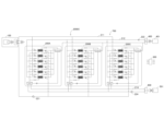
- Fig. 1 is a diagram showing an example of an outline of hardware of a cold energy generating system according to a first embodiment of the present disclosure.
- Fig. 2 is a functional block diagram showing an example of a configuration of a control system of the cold energy generating system of Fig. 1. Note that Fig. 2 shows a simplified view of the entire steam turbine device of Fig. 1, and also shows a simplified view of the adsorption chiller 200 of Fig. 1.
- a cold heat generating system 1000A includes a steam turbine device 100, an adsorption refrigeration device 700, and a control device 300.
- the adsorption refrigeration device 700 includes an adsorption refrigerator 200, a radiator 400, and a cold heat output device 500.
- the steam turbine device 100 is connected to the heat source 10 through a heat transfer structure in the first evaporator 101, and is connected to the adsorption chiller 200 through a second heat medium circulation path 211 in the first condenser 102.
- the adsorption chiller 200 is connected to the first condenser 102 of the steam turbine device 100 through the second heat medium circulation path 211 in the adsorber 202 described below, is connected to the radiator 400 through a third heat medium circulation path 212 in the adsorber 202 and the second condenser 204, and is connected to the cold heat output device 500 through a fourth heat medium circulation path 214 in the second evaporator 201.
- the radiator 400 radiates heat to the cooling body 401.
- the cold heat output device 500 outputs cold heat to the cold heat load 501.
- the control device 300 controls the operation of the cold heat generation system 1000A through a control system described below.
- the cold energy generating system 1000A is generally operated as follows under the control of the control device 300.
- the heat input to the cold energy generating system 1000A or output from the cold energy generating system 1000A is identified using symbols Q1 to Q5.
- the "heat quantities" of Q1 to Q5 are identified using symbols (Q1) to (Q5).
- the steam turbine device 100 receives evaporator input heat Q1 from the heat source 10 in the first evaporator 101, and inputs turbine input heat Q2 from this evaporator input heat Q1 to the steam turbine 103A to generate power.
- the steam turbine device 100 then discharges condensation exhaust heat Q3 that was not used to generate power in the steam turbine 103A to the second heat medium circulation path 211 in the first condenser 102.
- the adsorption refrigerator 200 uses the condensation waste heat Q3 discharged to the second heat medium circulation path 211 as a working heat source to make the adsorber 202 perform the adsorption and regeneration operation of the refrigerant.
- the heat generated by the heat generating element Q5 of the cold load 501 is pumped up as cold output from the cold load 501 via the fourth heat medium circulation path 214 and the cold heat output device 500, and in the adsorber 202 and the second condenser 204, the refrigeration waste heat Q4 is released to the cooling element 401 via the third heat medium circulation path 212 and the radiator 400.
- the steam turbine device 100 includes a Rankine cycle 110.
- the Rankine cycle 110 includes a first evaporator 101, a steam turbine 103A, a first condenser 102, a first heat medium tank 105, and a first heat medium circulation path 106.
- the first evaporator 101 evaporates the liquid first heat medium by the evaporator input heat Q1 received from the heat source 10 to generate the vapor first heat medium.
- the amount of heat of the evaporator input heat Q1 may be referred to as the "amount of received heat (Q1)".
- the first evaporator 101 is not particularly limited as long as it can evaporate the heat medium, and a known heat medium evaporator can be used as the first evaporator 101. For example, a boiler can be used as the first evaporator 101.
- the heat source 10 is not particularly limited. Examples of the heat source 10 include a geothermal energy utilization facility, a solar energy utilization facility, a factory, and a waste incineration facility (waste disposal plant). Examples of the factory include a chemical plant, a steel mill, a paper mill, and a general factory.
- the heat source 10 transmits the amount of heat generated or the amount of exhaust heat to the heat reception amount acquisition unit 340 as heat reception amount data described later.
- the heat source 10 also has a heat generation amount control unit 11, and receives a heat generation amount control command from the heat reception amount control circuit 320 of the control device 300 of the cold heat generation system 1000A, and controls the amount of heat generated or the amount of exhaust heat based on the received heat.
- a mechanism for adjusting the flow rate of the heat medium may be provided in the flow path of the heat medium that transports the exhaust heat from the heat source 10 to the first evaporator 101.
- the first heat medium is pure water in a normal Rankine cycle 110, and in rare cases, an organic solvent such as pentane or hexane is used for the purpose of operating with a low-temperature heat source (organic Rankine cycle).
- organic Rankine cycle an organic solvent such as pentane or hexane is used for the purpose of operating with a low-temperature heat source.
- the present disclosure is applicable to both the normal Rankine cycle 110 and the organic Rankine cycle.
- the steam turbine 103A generates rotational power by a first heat medium in a vapor state.
- the steam turbine 103A is not particularly limited, and a known steam turbine can be used as the steam turbine 103A.
- the rotating shaft of the steam turbine 103A is connected to a power unit 103B, and the power unit 103B is driven by the rotational power.
- the steam turbine 103 and the power unit 103B constitute a steam turbine unit 103.
- the power unit 103B is a device that performs work by power, and examples of the power unit include a generator and a machine tool.
- the power unit 103B is constituted by a generator.
- the generator as the power unit will be referred to as "generator 103B".
- the first condenser 102 condenses the first heat medium in a vapor state after rotating the steam turbine 103A by heat exchange with the second heat medium to generate the first heat medium in a liquid state.
- the first condenser 102 is composed of a heat exchanger, and the first heat medium flows through a primary flow path and the second heat medium flows through a secondary flow path.
- a known condenser can be used as the first condenser 102.
- the first heat medium tank 105 temporarily stores the liquid first heat medium produced in the first condenser 102.
- the first heat medium tank 105 is not particularly limited, and a known heat medium tank can be used as the first heat medium tank 105.
- the first heat medium circulation path 106 includes a first heat medium circulation flow path and a first heat medium pump 104.
- the first heat medium circulation flow path is a closed flow path that extends from the outlet of the first evaporator 101, passes through the steam turbine 103A, the primary side flow path of the first condenser 102, and the first heat medium tank 105, and returns to the inlet of the first evaporator 101.
- the first heat medium pump 104 is provided between the first heat medium tank 105 and the first evaporator 101 in the first heat medium circulation flow path.
- the first heat medium pump 104 pumps the liquid first heat medium toward the first evaporator 101, thereby circulating the first heat medium through the first heat medium circulation flow path.
- the first heat medium pump 104 is not particularly limited as long as it can pump the fluid while controlling the flow rate, and a known fluid pump can be used as the first heat medium pump 104.
- the second heat medium circulation path 211 includes a second heat medium circulation flow path and a second heat medium pump 221.
- the second heat medium circulation flow path is a closed flow path that extends from the outlet of the secondary side flow path of the first condenser 102, passes through the first and second adsorbers 202A and 202B arranged in parallel to each other of the adsorption chiller 200, and returns to the inlet of the secondary side flow path of the first condenser 102.
- the second heat medium pump 221 is provided between the first and second adsorbers 202A and 202B arranged in parallel to each other and the inlet of the first condenser 102 in the second heat medium circulation flow path.
- the second heat medium pump 221 circulates the second heat medium through the second heat medium circulation flow path by pumping the second heat medium toward the inlet of the secondary side flow path of the first condenser 102.
- the second heat medium pump 221 is not particularly limited as long as it can pump the fluid while controlling the flow rate, and a known fluid pump can be used as the second heat medium pump 221.
- the second heat medium and the third heat medium inevitably mix in small amounts at the timing of the adsorption operation and the regeneration operation. Therefore, the second heat medium needs to be the same substance as the third heat medium, and for reasons described below, the third heat medium is water, and therefore the second heat medium is also water.
- the adsorption chiller 200 includes an adsorption refrigeration cycle 210.
- the adsorption refrigeration cycle 210 includes a second evaporator 201, first and second adsorbers 202A and 202B, a second condenser 204, a refrigerant circulation path 213, and an adsorption regeneration valve system 209.
- the second evaporator 201 evaporates the liquid refrigerant by heat exchange with the fourth heat medium to generate a vapor refrigerant.
- the refrigerant is not particularly limited as long as it is a low-temperature heat medium. Pure water is used as the refrigerant.
- the second evaporator 201 is not particularly limited as long as it can evaporate the refrigerant, and a known refrigerant evaporator can be used as the second evaporator 201.
- the first and second adsorption devices 202A and 202B are both sealed containers having a refrigerant inlet, a refrigerant outlet, a heating/cooling medium inlet, and a heating/cooling medium outlet, and each accommodates an adsorption body 203A or 203B.
- adsorption devices 202 when a plurality of (here, two) adsorption devices 202A and 202B are collectively referred to, they are referred to as adsorption devices 202.
- a plurality of (here, two) adsorption devices 203A and 203B are collectively referred to, they are referred to as adsorption bodies 203.
- the adsorption body of the i-th adsorption device may be referred to as the i-th adsorption device.
- i is an integer of 1 or more.
- the number of adsorption devices 202 is not particularly limited, and may be 1. However, usually, the number of adsorption devices 202 is 2. This is because while one of the first and second adsorption devices 202A and 202B performs an adsorption operation and a regeneration operation, the other can perform a regeneration operation and an adsorption operation, and continuous refrigeration output can be obtained by continuously compressing the refrigerant.
- the adsorbent 203 is made of a material such as silica gel or zeolite.
- zeolite is preferred as a material for making up the adsorbent 203 for the following reasons.
- Japanese Patent No. 4,669,914 states that a specific zeolite-based adsorbent can be regenerated at 55°C under optimal operating conditions.
- the inventors experimentally confirmed that the adsorption capacity of the zeolite-based adsorbent changes from 0% to 100% while the regeneration temperature changes from 40°C to 65°C under the condition that the temperature of the cooling water (third heat medium) and the temperature of the cold water (fourth heat medium) are normal temperatures taking into account seasonal variations.
- the inventors have found that the control of the temperature of the hot water (second heat medium) input to the adsorption refrigerator is the main adjustment mechanism for the heat balance of the cold generation system, and that when the temperature of the hot water (second heat medium) is in this range, it is possible to suppress the condensation temperature (condensation temperature of the first heat medium) to 70°C or less by rationally designing the condenser (first condenser). Therefore, it is preferable to construct the adsorbent 203 from a material such as zeolite.
- Adsorbent 203 When cooled by the third heat medium whose temperature has been reduced, the adsorbent 203 adsorbs the vapor-phase refrigerant, and when heated by the second heat medium whose temperature has been increased by heat exchange with the first heat medium in the vapor phase, the adsorbent 203 releases (desorbs) the adsorbed refrigerant as vapor (gas).
- the second condenser 204 condenses the vapor refrigerant released from the adsorbent 203 through heat exchange with the third heat medium to generate a liquid refrigerant.
- the second condenser 204 is configured as a heat exchanger, in which the refrigerant flows through a primary flow path and the third heat medium flows through a secondary flow path.
- a known refrigerant condenser can be used as the second condenser 204.
- the refrigerant circulation path 213 includes a refrigerant circulation flow path and a refrigerant pump 223.
- the refrigerant circulation flow path is a closed flow path formed so as to extend from the outlet of the second evaporator 201, pass through the adsorber 202 and the primary side flow path of the second condenser 204, and return to the inlet of the second evaporator 201.
- the refrigerant pump 223 is provided between the second condenser 204 and the second evaporator 201 in the refrigerant circulation flow path.
- the refrigerant pump 223 pumps the liquid refrigerant toward the inlet of the second evaporator 201, thereby circulating the refrigerant through the refrigerant circulation flow path.
- the refrigerant pump 223 is not particularly limited as long as it can pump the fluid while controlling the flow rate, and a known fluid pump can be used as the refrigerant pump 223.
- the adsorption regeneration valve system 209 together with the operation control circuit 330, constitutes an adsorption regeneration control mechanism, and under the control of the operation control circuit 330, in an adsorption operation, each of the adsorbers 202A, 202B is connected to the second evaporator 201 and interposed between the radiator 400 and the second condenser 204 in the third heat medium circulation path 212 so that the adsorbents 203A, 203B adsorb the refrigerant, and in a regeneration operation, each of the adsorbers 202A, 202B is connected to the second condenser 204 and interposed in the second heat medium circulation path 211 so that the adsorbents 203A, 203B release the refrigerant to regenerate.
- the adsorption regeneration valve system 209 includes first and second inlet side refrigerant on-off valves 205A, 205B, first and second outlet side refrigerant on-off valves 206A, 206B, first and second inlet side heat medium switching valves 207A, 207B, and first and second outlet side heat medium switching valves 208A, 208B.
- the first and second inlet side refrigerant on-off valves 205A and 205B are both configured as on-off valves, and are respectively interposed between the refrigerant inlets of the first and second adsorbers 202A and 202B and the second evaporator 201 in the refrigerant circulation flow path.
- the first and second outlet side refrigerant on-off valves 206A, 206B are both configured as on-off valves, and are respectively interposed between the refrigerant outlets of the first and second adsorbers 202A, 202B and the second condenser 204 in the refrigerant circulation flow path.
- the first and second inlet side heat medium switching valves 207A, 207B are both configured as three-way valves, with their first ports connected to the heating/cooling heat medium inlets of the first and second adsorbers 202A, 202B, respectively, their second ports connected to the outlet of the secondary side flow path of the first condenser 102 via a second heat medium circulation flow path described below, and their third ports connected to the outlet of the radiator via a third heat medium circulation flow path described below.
- the first and second outlet side heat medium switching valves 208A, 208B are both configured as three-way valves, with their first ports connected to the heating/cooling heat medium outlets of the first and second adsorption devices 202A, 202B, respectively, their second ports connected to the inlet of the secondary side flow path of the first condenser 102 via a second heat medium circulation flow path described below, and their third ports connected to the inlet of the second condenser 204 via a third heat medium circulation flow path described below.
- the radiator 400 radiates heat from the third heat medium, which has been heated by heat exchange with the vapor-state refrigerant in the second condenser 204 , through heat exchange with the cooling body 401 , thereby lowering the temperature.
- the radiator 400 is not particularly limited as long as it can exchange heat between the heat medium and the cooling body 401.
- Examples of the radiator 400 include a cooling tower (open type heat exchanger), an electric heat pump, and a closed type heat exchanger.
- the cooling body 401 is not particularly limited as long as it can cool the heat medium. Examples of the cooling body 401 include air (atmosphere), water, etc.
- the third heat medium circulation path 212 includes a third heat medium circulation flow path and a third heat medium pump 222.
- the third heat medium circulation flow path is a closed flow path that extends from the outlet of the radiator 400, passes through the first and second adsorbers 202A and 202B arranged in parallel with each other of the adsorption chiller 200, and a secondary side flow path of the second condenser 204, and returns to the inlet of the radiator 400.
- the third heat medium pump 222 is provided in the third heat medium circulation flow path between the outlet of the radiator 400 and the first and second adsorbers 202A and 202B arranged in parallel with each other.
- the third heat medium pump 222 pumps the third heat medium toward the first and second adsorbers 202A and 202B, thereby circulating the third heat medium through the third heat medium circulation flow path.
- the third heat medium pump 222 is not particularly limited as long as it can pump the fluid while controlling the flow rate, and a known fluid pump can be used as the third heat medium pump 222.
- the third heat medium is water. This is because a system in which the third heat medium is water, the radiator 400 is a cooling tower (open heat exchanger), and the cooling body 401 is air (atmosphere), and in which the latent heat of vaporization of the third heat medium is used to radiate heat and cool the air, is common and preferable.
- the cold energy output device 500 outputs the cold energy of the fourth heat medium, the temperature of which has been lowered by heat exchange with the liquid refrigerant, to the cold energy load 501.
- the cold energy output device 500 transmits cold energy amount data, which will be described later, to the cold energy amount acquisition unit 350. This is also fine.
- the cold heat output device 500 is not particularly limited as long as it can exchange heat with the heat generating element of the cold heat load 501.
- a general example of the cold heat output device 500 is a heat exchanger, and a specific example is an indoor unit of an air conditioning facility (regardless of size).
- Examples of the cold heat load 501 include a DC, a food factory, a general factory, etc.
- the cooling load 501 may transmit cooling amount data, which will be described later, to the cooling amount acquisition unit 350 .
- the fourth heat medium circulation path 214 includes a fourth heat medium circulation flow path and a fourth heat medium pump 224.
- the fourth heat medium circulation flow path is a closed flow path that extends from the outlet of the secondary side flow path of the second evaporator 201, passes through the cold heat output device 500, and returns to the inlet of the secondary side flow path of the second evaporator 201.
- the fourth heat medium pump 224 is provided between the cold heat output device 500 and the inlet of the second evaporator 201 in the fourth heat medium circulation flow path.
- the fourth heat medium pump 224 pumps the fourth heat medium toward the inlet of the secondary side flow path of the second evaporator 201, thereby circulating the fourth heat medium through the fourth heat medium circulation flow path.
- the fourth heat medium pump 224 is not particularly limited as long as it can pump the fluid while controlling the flow rate, and a known fluid pump can be used as the fourth heat medium pump 224.
- Examples of the fourth heat medium include water and antifreeze. If the fourth heat medium is water, there is a possibility that it will be cooled and frozen in the second evaporator 201, but this is not the case with antifreeze, so it is preferable that the fourth heat medium is antifreeze.
- the control device 300 is disposed at an appropriate location in the cold energy generation system 1000A.
- the control device 300 includes a computer and a communication device for communicating with each control element.
- the computer includes a processor Pr and a memory Me.
- the control device 300 controls the operation of the cold energy generation system 1000A.
- the control device 300 may be configured as a single control device performing centralized control, or may be configured as multiple control devices performing distributed control. The detailed configuration and operation of the control device 300 will be described below.
- control system of the cold generating system 1000 ⁇ /b>A includes a control device 300 and a first heat medium temperature sensor 601 .
- the control device 300 includes a system control circuit 310, a received heat amount acquisition unit 340, and a cold heat amount acquisition unit 350.
- the control device 300 includes a system control circuit 310, a received heat amount control circuit 320, and an operation control circuit 330.
- the system control circuit 310, the received heat amount acquisition unit 340, and the cold heat amount acquisition unit 350 each include a communication unit and a processing unit, and receive or transmit data that is to be processed or has been processed by the processing unit via the communication unit.
- the processing units of the system control circuit 310, the heat reception acquisition unit 340, and the cold heat acquisition unit 350 are functional blocks (functional modules) that are realized by the processor Pr reading and executing a dedicated control program stored in the memory Me.
- the functions of the control elements disclosed herein can be performed using circuits or processing circuits including general purpose processors, special purpose processors, integrated circuits, ASICs (Application Specific Integrated Circuits), conventional circuits, and/or combinations thereof, configured or programmed to perform the disclosed functions.
- the processor Pr is considered a processing circuit or circuit because it includes transistors and other circuits.
- a "circuit”, “unit”, or “portion” is hardware that performs the recited functions or hardware that is programmed to perform the recited functions.
- the hardware may be hardware disclosed herein or other known hardware that is programmed or configured to perform the recited functions.
- the "circuit", "unit”, or “portion” is a combination of hardware and software, where the software is used to configure the hardware and/or the processor Pr.
- the heat reception amount control circuit 320 controls the amount of heat received (Q1) from the heat source 10 in accordance with the output of cold heat to the cold heat load 501 so that the condensation temperature of the first heat medium is maintained within a first predetermined temperature range, based on the condensation temperature of the first heat medium detected by the first heat medium temperature sensor 601, the amount of heat received data acquired by the heat reception amount acquisition unit 340, and the amount of cold heat data acquired by the cold heat amount acquisition unit 350.
- the heat reception amount control circuit 320 transmits a heat generation amount control command to the heat generation amount control unit 11 of the heat source 10, and controls the heat generation amount (Q1) or the amount of exhaust heat (Q1) of the heat source 10, based on the heat generation amount control command received by the heat generation amount control unit 11.
- the first predetermined temperature range is determined taking into consideration the allowable range of efficiency of the steam turbine 103A of the steam turbine device 100.
- the first predetermined temperature range is, for example, 20°C or higher and 70°C or lower. If the condensation temperature of the first heat medium is 70°C or lower, the decrease in efficiency of the steam turbine 103A can be suppressed within the allowable limit. Also, if the condensation temperature of the first heat medium is 70°C or lower, the required temperature difference can be set taking into consideration the preferred temperature range of the second heat medium (40°C to 65°C), and the first condenser 102 can be designed within a reasonable heat transfer area range. On the other hand, the lower limit temperature of the first predetermined temperature range is regulated by the temperature of the cooling body 401.
- the reason is as follows.
- the adsorbent 203 is heated by the second heat medium and cooled by the third heat medium, so that the temperature of the second heat medium is higher than the temperature of the third heat medium.
- the third heat medium is cooled by the cooling body 401, so the temperature of the third heat medium is higher than the temperature of the cooling body 401. Therefore, in order to design the temperature of the second heat medium to be low, it is necessary to design the temperature of the cooling body 401 to be low.
- the practical lower limit temperature of the cooling body 401 is about 10°C for groundwater. Therefore, if the first predetermined temperature range is 20°C or higher, it is possible to maintain good efficiency of the steam turbine 103A without any practical difficulties.
- the heat receiving control circuit 320 stores this first predetermined temperature range in the memory unit in advance.
- the heat receiving amount control circuit 320 is an example of an aspect of the heat balance control circuit in embodiment 1.
- the heat balance control circuit constitutes a heat balance control mechanism together with the first heat medium temperature sensor 601, the heat receiving amount acquisition unit 340, and the cold heat amount acquisition unit 350, and controls the heat balance of the steam turbine device 100 and the adsorption refrigeration device 700 so that the condensation temperature of the first heat medium is maintained within a first predetermined temperature range.
- the operation control circuit 330 controls operations other than the heat balance of the cold generation system 1000A.
- the operation control circuit 330 controls the operation of the adsorption regeneration valve system 209. Therefore, the operation control circuit 330 and the adsorption regeneration valve system 209 constitute an adsorption regeneration control mechanism.
- the heat receiving communication unit receives the received heat amount data from the heat source 10, and the received heat amount processing unit appropriately processes the received received heat amount data, such as temporarily storing it.
- the received heat amount data is data indicating the amount of evaporator input heat Q1 discharged from the heat source 10 and received by the first evaporator 101 of the steam turbine device 100.
- the received heat amount data may include the amount of waste input.
- the received heat amount data may include the flow rate of the heat medium (e.g., hot water) that carries the exhaust heat from the factory.
- the received heat amount acquisition unit 340 may use these received heat amount data as they are as the "received heat amount (Q1)", or may convert these received heat amount data into heat amount to use as the "received heat amount (Q1)".
- Cold energy amount acquisition unit 350 In the cold energy amount acquisition unit 350, the cold energy communication unit receives cold energy amount data from the cold energy load 501 or the cold energy output device 500, and the cold energy amount processing unit appropriately processes the received cold energy amount data, such as temporarily storing it.
- the cold heat quantity data is data indicating the amount of heat of the heat source heat Q5 that the heat source of the cold heat load 501 releases in exchange for the cold heat supplied from the cold heat output device 500.
- the cold heat quantity data is data indicating the amount of heat of the heat source heat Q5 that the cold heat output device 500 pumps up from the cold heat load 501. Therefore, hereinafter, the "amount of heat of the heat source heat Q5" may be referred to as the "amount of cold heat (Q5)".
- the cold heat quantity data may include the power consumption of the DC.
- the cold heat quantity data may include the power consumption of the air conditioning equipment as the cold heat output device 500 of the factory.
- the cold heat quantity data may include the flow rate of the refrigerant of the refrigeration equipment.
- the cold energy amount acquisition unit 350 may use these cold energy amount data as "cold energy amount (Q5)" as is, or may convert these cold energy amount data into heat amount (negative heat amount) and use it as "cold energy amount (Q5)”.
- the first heat medium temperature sensor 601 is an example of an aspect of the condensation temperature correlated physical quantity sensor in the first embodiment.
- the first heat medium temperature sensor 601 detects the condensation temperature of the first heat medium in the steam turbine device 100.
- the first heat medium temperature sensor 601 is provided between the steam turbine 103A and the first condenser 102 in the first heat medium flow path.
- the first heat medium temperature sensor 601 is not particularly limited as long as it is a temperature sensor. Examples of the first heat medium temperature sensor 601 include a resistance temperature detector, a thermocouple, a radiation thermometer such as an infrared sensor, and the like.
- the first evaporator 101 evaporates the first heat medium by the evaporator input heat Q1 received from the heat source 10.
- the first heat medium circulation path 106 transports the turbine input heat Q2 to the steam turbine 103A by the vaporized first heat medium.
- the steam turbine 103A rotates the generator 103B, causing the generator 103B to generate electric power E1.
- the first heat medium circulation path 106 transports the vaporized first heat medium discharged from the steam turbine 103A to the first condenser 102.
- the first condenser 102 condenses the vaporized first heat medium.
- the first heat medium circulation path 106 returns the condensed liquid first heat medium to the first evaporator 101 through the first heat medium tank 105 and the first heat medium pump 104.
- the cold output device 500 outputs cold to the cold load 501, and in doing so receives heat Q5 from the heating element from the cold load 501 in exchange for the cold output.
- the fourth heat medium circulation path 214 transports this heat Q5 from the heating element to the second evaporator 201 by the fourth heat medium.
- the second evaporator 201 evaporates the refrigerant by the heat Q5 from the heating element.
- the radiator 400 also exchanges heat between the third heat medium and the cooling body 401 to radiate the refrigeration waste heat Q4, thereby lowering the temperature of the third heat medium.
- the third heat medium circulation path 212 transports the cooled third heat medium to the first and second adsorption devices 202A and 202B.
- the first condenser 102 exchanges heat between the first heat medium and the second heat medium to condense the first heat medium, thereby discharging condensation waste heat Q3 that was not used to drive the steam turbine 103A.
- the second heat medium circulation path 211 transports this condensation waste heat Q3 to the first and second adsorption devices 202A, 202B by the second heat medium.
- the adsorption regeneration valve system 209 causes the first and second adsorption devices 202A, 202B to perform an "adsorption operation” and a “regeneration operation.”
- the "adsorption operation” is an operation in which the adsorption body 203 in the adsorption device 202 adsorbs the refrigerant as vapor from the second evaporator 201, thereby removing the latent heat of vaporization of the vapor from the second evaporator 201 to generate refrigeration output.
- the "regeneration operation” is an operation in which the adsorption body 203 in the adsorption device 202 releases the refrigerant adsorbed in the adsorption operation as vapor, thereby regenerating the adsorption function of the adsorption body 203.
- the adsorption regeneration valve system 209 opens the first inlet side refrigerant on-off valve 205A and closes the first outlet side refrigerant on-off valve 206A during the first half of the cycle of the adsorption regeneration operation of the first and second adsorption devices 202A, 202B (hereinafter simply referred to as the "adsorption regeneration operation cycle time") to connect the first adsorption device 202A to the second evaporator 201, and switches the connection of the inlet of the first adsorption device 202A to the third heat medium circulation path 212 by the first inlet side heat medium switching valve 207A, and switches the connection of the outlet of the first adsorption device 202A to the third heat medium circulation path 212 by the first outlet side heat medium switching valve 208A, thereby interposing the first adsorption device 202A between the radiator 400 and the second condenser 204 in the third heat medium circulation path 212.
- the adsorbent 203 opens the first inlet side
- the adsorption regeneration valve system 209 closes the second inlet side refrigerant on-off valve 205B and opens the second outlet side refrigerant on-off valve 206B to connect the second adsorber 202B to the second condenser 204, and switches the connection destination of the inlet of the second adsorber 202B to the second heat medium circulation path 211 by the second inlet side heat medium switching valve 207B and switches the connection destination of the outlet of the second adsorber 202B to the second heat medium circulation path 211 by the second outlet side heat medium switching valve 208B, thereby inserting the second adsorber 202B into the second heat medium circulation path 211.
- the adsorbent 203B of the second adsorber 202B is heated by the second heat medium and releases the adsorbed refrigerant.
- the adsorption regeneration valve system 209 closes the first inlet side refrigerant on-off valve 205A and opens the first outlet side refrigerant on-off valve 206A to connect the first adsorber 202A to the second condenser 204, and switches the connection destination of the inlet of the first adsorber 202A to the third heat medium circulation path 212 by the first inlet side heat medium switching valve 207A and switches the connection destination of the outlet of the first adsorber 202A to the second heat medium circulation path 211 by the first outlet side heat medium switching valve 208A, thereby inserting the first adsorber 202A into the second heat medium circulation path 211.
- the adsorbent 203A of the first adsorber 202A is heated by the second heat medium and releases the adsorbed refrigerant.
- the adsorption regeneration valve system 209 opens the second inlet side refrigerant on-off valve 205B and closes the second outlet side refrigerant on-off valve 206B to connect the second adsorber 202B to the second evaporator 201, and switches the connection destination of the inlet of the second adsorber 202B to the third heat medium circulation path 212 by the second inlet side heat medium switching valve 207B and switches the connection destination of the outlet of the second adsorber 202B to the third heat medium circulation path 212 by the second outlet side heat medium switching valve 208B, thereby interposing the second adsorber 202B between the radiator 400 and the second condenser 204 in the third heat medium circulation path 212.
- the adsorbent 203B of the second adsorber 202B is cooled by the third heat medium and adsorbs the vapor-state refrigerant from the second evaporator 201.
- the second condenser 204 exchanges heat with the third heat medium to condense the vapor refrigerant released from the adsorbent 203A of the first adsorber 202A or the adsorbent 203B of the second adsorber 202B.
- the refrigerant circulation path 213 sends the condensed liquid refrigerant to the second evaporator 201 by the refrigerant pump 223.
- the third heat medium circulation path 212 also carries the heat obtained by the third heat medium cooling the adsorbent 203A of the first adsorbent 202A or the adsorbent 203B of the second adsorbent 202B and exchanging heat with the refrigerant in the second condenser 204 to the radiator 400 by the third heat medium.
- the radiator 400 radiates the carried heat to the cooling body 401 as refrigeration waste heat Q4.
- the adsorption chiller 200 uses the condensation waste heat Q3 discharged to the second heat medium circulation path 211 as a working heat source to have the adsorber 202 perform the adsorption and regeneration operation of the refrigerant, so that in the second evaporator 201, heat generation Q5 of the heat load 501 is pumped up as cold heat output from the cold load 501 via the fourth heat medium circulation path 214 and the cold heat output device 500, and in the adsorber 202 and second condenser 204, refrigeration waste heat Q4 is released to the cooling body 401 via the third heat medium circulation path 212 and the radiator 400.
- the heat balance control is performed by a heat reception control circuit 320 which is an example of the heat balance control circuit according to the first embodiment.
- the first heat medium circulation path 106 is a Rankine cycle circuit that receives evaporator input heat Q1 from the heat source 10, inputs turbine input heat Q2 out of the evaporator input heat Q1 to the steam turbine 103A, and discharges condensation exhaust heat Q3 that is not used for generating power in the steam turbine 103A from the first condenser 102.
- the second heat medium circulation path 211 is a circuit that circulates the second heat medium for heating used in the regeneration operation of the adsorption refrigeration device 700.
- the second heat medium is heated by the condensation waste heat Q3 in the first condenser 102 and supplied to the adsorption refrigeration device 700, where it is consumed as heat, and then returns to the first condenser 102.
- the third heat medium circulation path 212 is a circuit that circulates the third heat medium for cooling used in the adsorption operation of the adsorption refrigeration device 700. After the third heat medium is heated by the adsorption refrigeration device 700, the heat generated by the third heat medium is dissipated by the radiator 400 as refrigeration waste heat Q4.
- the fourth heat medium circulation path 214 is a circuit that circulates the fourth heat medium that carries the cold energy of the adsorption refrigeration device 700.
- the fourth heat medium outputs the cold energy generated in the second evaporator 201 to the cold energy load 501 in the cold energy output device 500, and at the same time, receives the heat energy Q5 of the heating element of the cold energy load 501 in exchange for the cold energy, and carries this back to the second evaporator 201.
- the cold energy generation system 1000A performs a series of Rankine cycle operations, in which the steam turbine 103A of the primary cycle uses the turbine input heat Q2 from the first evaporator 101 to drive the power unit (here, the generator) 103B and the first condenser 102 discharges the condensation waste heat Q3, by heat transfer through the four types of heat medium circulation paths 106, 211, 212, and 214, and the adsorption refrigeration device 700 of the secondary cycle generates refrigeration output using the condensation waste heat Q3 from the first condenser 102 as a working heat source, and this refrigeration output is used to pump up the heat generated by the heating element Q5 of the cold energy load 501 and to discard the refrigeration waste heat Q4 outside the system.
- the condensation temperature (turbine back pressure) is a barometer of the heat balance state. That is, assuming that the adsorption refrigeration system 700 is operating optimally and ⁇ 3 is in the normal range, if the heat generated by the heating element Q5 is too small compared to the evaporator input heat Q1, the adsorption refrigeration system 700 will only perform refrigeration work that balances with the heat generated by the heating element Q5, so the heat consumption of the adsorption refrigeration system 700 will decrease accordingly, and the condensation waste heat Q3 that should be removed will not be removed, and the condensation temperature (turbine back pressure) will rise.
- the heat quantity of the evaporator input heat Q1 is controlled relative to the heat quantity of the heat generated by the heating element Q5 so that the condensation temperature of the first heat medium in the first condenser 102 falls within a predetermined appropriate range (here, the first predetermined temperature range).
- a predetermined appropriate range here, the first predetermined temperature range.
- Heat balance control is performed by the heat reception control circuit 320 as follows:
- the heat receiving amount acquisition unit 340 acquires heat receiving amount data from the heat source 10, and obtains the heat receiving amount (Q1) from the heat receiving amount data.
- the cold heat amount acquisition unit 350 acquires cold heat amount data from the cold heat output device 500 or the cold heat load 501, and obtains the cold heat amount (Q5) from the cold heat amount data.
- the heat reception amount control circuit 320 acquires the amount of heat received from the heat reception amount acquisition unit 340 and acquires the amount of cold heat (Q5) from the cold heat amount acquisition unit 350.
- the heat reception amount control circuit 320 also acquires the condensation temperature of the first heat medium from the first heat medium temperature sensor 601. Then, based on the acquired amount of heat received (Q1) and amount of cold heat (Q5), the heat reception amount control circuit 320 generates a heat generation control command such that the condensation temperature of the first heat medium is maintained within a first predetermined temperature range, and transmits this to the heat generation amount control unit 11 of the heat source 10.
- the heat generation amount or exhaust heat amount of the heat source 10 is controlled based on the heat generation amount control command received by the heat generation amount control unit 11 of the heat source 10.
- the heat balance of the cold generation system 1000A is controlled so that the condensation temperature of the first heat medium is maintained within a first predetermined temperature range.
- FIG. 5 is a diagram illustrating an example of an outline of hardware of a cold heat generating system 1000B according to a modification of the first embodiment of the present disclosure.
- a turbine back pressure sensor 610 that detects the back pressure of the steam turbine 103A is used as the condensation temperature correlation physical quantity sensor.
- the rest is the same as the basic configuration of the above-mentioned embodiment 1.
- the turbine back pressure sensor 610 is provided between the steam turbine 103A and the first condenser 102 in the first heat medium flow path.
- Examples of the turbine back pressure sensor 610 include a diffusion type semiconductor sensor and a metal thin film type sensor.
- the back pressure of the steam turbine 103A corresponds one-to-one with the condensation temperature of the first heat medium.
- the heat receiving amount control circuit 320 controls the heat receiving amount (Q1) according to the cold heat amount (Q5) so that the turbine back pressure detected by the turbine back pressure sensor 610 is maintained within a predetermined pressure range of the turbine back pressure corresponding to a first predetermined temperature range of the condensation temperature of the first heat medium.
- the amount of heat received (Q1) is controlled according to the amount of cold heat (Q5) so that the condensation temperature of the first heat medium is maintained within the first predetermined temperature range, and thus the heat balance of the cold heat generation system 1000A is controlled so that the condensation temperature of the first heat medium is maintained within the first predetermined temperature range.
- the heat balance control mechanism controls the heat balance of the steam turbine device 100 and the adsorption refrigeration device 700 so that the condensation temperature of the first heat medium in the Rankine cycle is maintained within a first predetermined temperature range. Therefore, the outlet pressure (turbine back pressure) of the steam turbine 103A can be maintained within a range corresponding to the first predetermined temperature range of the condensation temperature of the first heat medium, and thus the compression ratio of the steam turbine 103A can be maintained within a certain range.
- the exhaust heat of the steam turbine drive can be used to generate cold heat for the cold load 501 while preventing a decrease in the efficiency of the steam turbine 103A, and thus cold heat generation systems 1000A and 1000B that can effectively utilize the exhaust heat of the steam turbine drive can be provided.
- the heat reception control circuit 320 controls the amount of heat received (Q1) from the heat source 10 in accordance with the output of cold to the cold load 501 so that the condensation temperature of the first heat medium is maintained within the first predetermined temperature range. Therefore, even if the amount of cold load of the cold load 501 fluctuates, the amount of heat received (Q1) from the heat source 10 can be controlled to achieve heat balance between the steam turbine device 100 and the adsorption refrigeration device 700 so that the condensation temperature of the first heat medium is maintained within the first predetermined temperature range.
- (Embodiment 2) 6 is a functional block diagram showing an example of the configuration of a control system of a cold energy generation system 1000C according to the second embodiment of the present disclosure.
- the heat balance control mechanism controls the heat COP of the adsorption refrigeration device 700 as heat balance control so that the condensation temperature of the first heat medium is maintained within a first predetermined temperature range and cold energy corresponding to the cold energy load amount of the cold energy load 501 is output.
- the second embodiment differs from the first embodiment (including the modified example) in this respect, and is similar to the first embodiment (including the modified example) in other respects. The difference will be described in detail below.
- the heat balance control mechanism includes a heat COP control circuit 321 instead of the heat reception amount control circuit 320 of the first embodiment, and further includes a second heat medium temperature sensor 602.
- the control device 300 does not include the heat reception amount acquisition unit 340.
- the heat COP control circuit 321 includes a second heat medium flow rate control circuit 325.
- the second heat medium temperature sensor 602 is provided between the outlet of the first condenser 102 in the second heat medium circulation path 211 and the first and second adsorbers 202A, 202B of the adsorption chiller 200.
- the second heat medium temperature sensor 602 detects the supply temperature of the second heat medium supplied from the first condenser 102 to the adsorption chiller 200.
- a known temperature sensor can be used as the second heat medium temperature sensor 602.
- the evaporator input heat Q1, the turbine input heat Q2, the condensation waste heat Q3, the refrigeration waste heat Q4, and the heat generation element heat Q5 are in heat balance. Therefore, the temperatures of the second to fourth heat media are determined according to the operating conditions of the adsorption refrigeration device 700 so that the cold energy generation system 1000C is in heat balance.
- control of the temperature T2 of the second heat medium (hereinafter referred to as the supply temperature of the second heat medium) fed into the adsorption chiller 200 is the main adjustment mechanism for the heat balance of the cold generation system 1000C, and when the supply temperature T2 of the second heat medium is within this range (hereinafter referred to as the second predetermined temperature range), it is possible to suppress the condensation temperature of the first heat medium to 70°C or less by rationally designing the first condenser 102.
- the thermal COP of the adsorption refrigeration device 700 (adsorption chiller 200) can be reduced to a desired value by lowering the supply temperature of the second heat medium to the adsorption chiller 200, and this reduction in the supply temperature of the second heat medium can be achieved by reducing the flow rate (flow rate per unit time) of the second heat medium flowing through the second heat medium circulation path 211.
- the heat COP control circuit 321 controls the heat COP of the adsorption refrigeration device 700 so that the condensation temperature of the first heat medium is maintained within a first predetermined temperature range and cold energy corresponding to the cold load amount of the cold load 501 is output.
- the second heat medium flow control circuit 325 controls the flow rate of the second heat medium flowing through the second heat medium circulation path 211 so that the supply temperature of the second heat medium is maintained within a second predetermined temperature range.
- the second predetermined temperature range is set to a temperature range in which the condensation temperature of the first heat medium is maintained within the first predetermined temperature range. Such a second predetermined temperature range can be obtained by simulation, experiment, calculation, etc.
- the heat COP control circuit 321 stores the first and second predetermined temperature ranges in advance in a memory unit.
- the heat COP control circuit 321 acquires the cold energy amount (Q5) from the cold energy amount acquisition unit 350 and acquires the supply temperature of the second heat medium from the second heat medium temperature sensor 602. Then, the heat COP control circuit 321 including the second heat medium flow control circuit 325 controls the operation amount P2 of the second heat medium pump 221 so that the supply temperature of the second heat medium is maintained within a second predetermined temperature range according to the cold energy amount (Q5). As a result, the heat COP of the adsorption refrigeration device 700 is controlled so that the condensation temperature of the first heat medium is maintained within the first predetermined temperature range and cold energy corresponding to the cold energy load amount of the cold energy load 501 is output.
- the thermal COP control circuit 321 controls the operating amount P2 of the second heat medium pump 221 based on the condensation temperature of the first heat medium detected by the first heat medium temperature sensor 601 so that the condensation temperature of the first heat medium is within a first predetermined temperature range.
- the thermal COP control circuit 321 controls the thermal COP of the adsorption refrigeration device 700 so that the condensation temperature of the first heat medium is maintained within the first predetermined temperature range and cold energy is output according to the cold energy load amount of the cold energy load 501. Therefore, even if the cold energy load amount fluctuates, the thermal COP of the adsorption refrigeration device 700 can be controlled to achieve thermal balance between the steam turbine device 100 and the adsorption refrigeration device 700 so that the condensation temperature of the first heat medium is maintained within the first predetermined temperature range.
- the second heat medium flow control circuit 325 controls the flow rate of the second heat medium flowing from the first condenser 102 to the adsorber 202 so that the supply temperature of the second heat medium is maintained within a second predetermined temperature range, and therefore the thermal COP of the adsorption refrigerator 200 is suitably adjusted so that the condensation temperature of the first heat medium is maintained within the first predetermined temperature range.
- FIG. 7 is a functional block diagram showing an example of the configuration of a control system of a cold heat generating system 1000D according to the third embodiment of the present disclosure.
- the cold generation system 1000D of embodiment 3 is different from the cold generation system 1000C of embodiment 2 in that the heat balance control mechanism includes an additional control circuit group and temperature sensor group.
- the thermal COP control circuit 321 includes third and fourth heat medium flow control circuits 326, 327
- the temperature sensor group includes third and fourth heat medium temperature sensors 603, 604 in addition to the first and second heat medium temperature sensors 601, 602.
- Embodiment 3 differs from embodiment 2 in these respects, but is similar to embodiment 2 in other respects. These differences will be explained in detail below.
- the third heat medium temperature sensor 603 is provided between the radiator 400 and the first and second adsorption devices 202A, 202B in the third heat medium circulation path 212.
- the third heat medium temperature sensor 603 detects the temperature of the third heat medium flowing from the radiator 400 to the first and second adsorption devices 202A, 202B.
- the fourth heat medium temperature sensor 604 is provided between the cold heat output device 500 and the inlet of the second evaporator 201 in the fourth heat medium circulation path 214.
- the fourth heat medium temperature sensor 604 detects the temperature of the fourth heat medium flowing from the cold heat output device 500 to the second evaporator 201.
- the third heat medium flow control circuit 326 controls the flow rate of the third heat medium so that the temperature of the third heat medium flowing from the radiator 400 to the adsorber 202 is maintained within a third predetermined temperature range.
- the third predetermined temperature range is set to a temperature range in which the adsorption and regeneration operations of the adsorber 202 are performed sufficiently. This third predetermined temperature range is determined by simulation, experiment, calculation, etc.
- the fourth heat medium flow control circuit 327 controls the flow rate of the fourth heat medium so that the temperature of the fourth heat medium flowing from the cold heat output device 500 to the second evaporator 201 is maintained within a fourth predetermined temperature range.
- the fourth predetermined temperature range is set to a temperature range in which the second evaporator 201 can sufficiently absorb the heat generation Q5 of the cold heat load 501.
- the fourth predetermined temperature range is determined by simulation, experiment, calculation, etc.
- the COP control circuit 321 including the second heat medium flow control circuit 325 performs the heat COP control of the second embodiment.
- the third heat medium flow control circuit 326 controls the operation amount of the third heat medium pump 222 based on the temperature of the third heat medium detected by the third heat medium temperature sensor 603 so that the temperature of the third heat medium is maintained within a third predetermined temperature range.
- the fourth heat medium flow control circuit 327 controls the operation amount of the fourth heat medium pump 224 based on the temperature of the fourth heat medium detected by the fourth heat medium temperature sensor 604 so that the temperature of the fourth heat medium is maintained within a fourth predetermined temperature range. This allows the second evaporator 201 to sufficiently absorb the heat Q5 of the cooling load 501.
- the heat pump operation of the adsorption refrigeration device 700 is stable, and the adsorption refrigeration device 700 exerts sufficient refrigeration capacity while appropriately maintaining the heat balance of the cold generation system 1000D.
- FIG. 8 is a functional block diagram showing an example of the configuration of a control system of a cold heat generating system 1000E according to a fourth embodiment of the present disclosure.
- the cold generation system 1000E of embodiment 4 has a heat balance control mechanism that includes an additional control circuit, a group of temperature sensors, and a group of flow rate sensors, and the heat balance control circuit 323 performs more advanced heat balance control.
- Embodiment 4 differs from embodiment 3 in these respects, but is otherwise similar to embodiment 3. The differences will be explained in detail below.
- the temperature sensor group includes three first heat medium temperature sensors 601a-601c, two second heat medium temperature sensors 602a, 602b, two third heat medium temperature sensors 603a, 603b, and two fourth heat medium temperature sensors 604a, 604b.
- the flow rate sensor group includes first to fourth heat medium flow rate sensors 611-614.
- the first heat medium temperature sensor 601a is provided between the outlet of the first evaporator 101 and the steam turbine 103A in the first heat medium circulation path 106, and detects the temperature of the first heat medium flowing from the first evaporator 101 to the steam turbine 103A.
- the first heat medium temperature sensor 601b is configured as the first heat medium temperature sensor 601 of embodiment 3, and detects the condensation temperature T1 of the first heat medium flowing from the first evaporator 101 to the steam turbine 103A.
- the first heat medium temperature sensor 601c is provided between the first heat medium tank 105 and the inlet of the first evaporator 101 in the first heat medium circulation path 106, and detects the temperature of the first heat medium flowing from the first condenser 102 to the first evaporator 101.
- the second heat medium temperature sensor 602a is configured as the second heat medium temperature sensor 602 of embodiment 3, and detects the supply temperature T2 of the second heat medium flowing from the first condenser 102 to the first and second adsorption devices 202A, 202B of the adsorption chiller 200.
- the second heat medium temperature sensor 602b is provided between the first and second adsorption devices 202A, 202B of the adsorption chiller 200 and the first condenser 102 in the second heat medium circulation path 211, and detects the temperature of the second heat medium flowing from the first and second adsorption devices 202A, 202B to the first condenser 102.
- the third heat medium temperature sensor 603a is provided between the second condenser 204 and the radiator 400 of the adsorption refrigerator 200 in the third heat medium circulation path 212, and detects the temperature of the third heat medium flowing from the second condenser 204 to the radiator 400.
- the third heat medium temperature sensor 603b is configured as the third heat medium temperature sensor 603 of embodiment 3, and detects the supply temperature T3 of the third heat medium flowing from the radiator 400 to the first and second adsorption devices 202A and 202B of the adsorption chiller 200.
- the fourth heat medium temperature sensor 604a is provided between the second evaporator 201 of the adsorption refrigerator 200 and the cold heat output device 500 in the fourth heat medium circulation path 214, and detects the temperature of the fourth heat medium flowing from the second evaporator 201 to the cold heat output device 500.
- the fourth heat medium temperature sensor 604b is configured as the fourth heat medium temperature sensor 604 of embodiment 3, and detects the supply temperature T4 of the fourth heat medium flowing from the cold heat output device 500 to the second evaporator 201 of the adsorption chiller 200.
- the first heat medium flow sensor 611 is provided between the first heat medium tank 105 and the first evaporator 101 in the first heat medium circulation path 106, and detects the flow rate of the first heat medium flowing from the first condenser 102 to the first evaporator 101.
- the second heat medium flow sensor 612 is provided at an appropriate location in the second heat medium circulation path 211 and detects the flow rate of the second heat medium.
- the third heat medium flow sensor 613 is provided at an appropriate location in the third heat medium circulation path 212 and detects the flow rate of the third heat medium.
- the fourth heat medium flow sensor 614 is provided at an appropriate location in the fourth heat medium circulation path 214 and detects the flow rate of the fourth heat medium.
- the first to fourth heat medium temperature sensors 601a to 601c, 602a, 602b, 603a, 603b, 604a, and 604b can be configured with known temperature sensors.
- the first to fourth heat medium flow rate sensors 611 to 614 can be, for example, known flow meters.
- the control device 300 also includes the heat reception amount acquisition unit 340 of embodiment 1, and the heat balance control circuit 323 has the functions of the heat reception amount control circuit 320 of embodiment 1 and the heat COP control circuit 321 of embodiment 3.
- the amount of heat transport can be easily calculated from the temperature difference between when a fluid flows into and out of a device and the circulating flow rate of the fluid.
- the relationship between steam temperature and specific enthalpy is a physical property value summarized in a steam table, and can be stored by the heat balance control circuit 323.
- the heat balance control circuit 323 directly calculates the heat received from the heat source 10 (Q1), the heat supplied to the steam turbine 103A (Q2), the heat supplied to the adsorption refrigeration device 700 (Q3), the refrigeration waste heat (Q4), and the heat generated by the cold load 501 (Q5) from the above (Equation 5) and stored information such as the steam table, the detection data from the first to fourth heat medium temperature sensors 601a to 601c, 602a, 602b, 603a, 603b, 604a, 604b, and the detection data from the first to fourth heat medium flow sensors 611 to 614.
- the heat balance control circuit 323 pre-stores experimental or theoretical values such as the relationship between the supply temperature T2 of the second heat medium, the supply temperature T3 of the third heat medium, and the supply temperature T4 of the fourth heat medium of the adsorption refrigeration device 700 and the efficiency of the adsorption refrigeration device 700, and also pre-stores experimental or theoretical values such as the relationship between the outside air temperature and the performance of the radiator 400, and the relationship between the steam temperature and the power generation efficiency.
- the target temperatures T1 to T4 and flow rates of the first to fourth heat media are instantly calculated for the target heat amounts of the received heat (Q1), the supplied heat (Q2, Q3), the refrigeration waste heat (Q4), and the generated heat (Q5), and the operation amounts P1 to P4 of the first to fourth heat medium pumps 104, 221, 222, and 224 corresponding to the first to fourth heat media, respectively, are precisely and quickly controlled.
- FIG. 9 is a flow chart showing an example of heat balance control of the cold heat generation system 1000E of FIG. 8. This heat balance control is performed by the heat balance control circuit 323.
- the heat balance control circuit 323 first determines whether there is room to vary the amount of heat received (Q1) (step S1). Specifically, if the amount of heat received (Q1) exceeds the amount of cold heat (Q5), the heat balance control circuit 323 determines that there is room to vary the amount of heat received (Q1) (YES in step S) and proceeds to step S2; otherwise, it determines that there is no room to vary the amount of heat received (Q1) (NO in step S1) and proceeds to step S10.
- step 2 the heat balance control circuit 323 determines whether the supply temperature T3 of the third heat medium is appropriate. Specifically, if the supply temperature T3 of the third heat medium is within the third predetermined temperature range (YES in step S2), the heat balance control circuit 323 proceeds to step S4, and if the supply temperature T3 of the third heat medium is not within the third predetermined temperature range (NO in step S2), the heat balance control circuit 323 controls the operating amount P3 of the third heat medium pump 222 until the supply temperature T3 of the third heat medium is within the third predetermined temperature range (YES in steps S3 and S2).
- step S4 the heat balance control circuit 323 determines whether the supply temperature T4 of the fourth heat medium is appropriate. Specifically, if the supply temperature T4 of the fourth heat medium is within the fourth predetermined temperature range (YES in step S4), the heat balance control circuit 323 proceeds to step S6, and if the supply temperature T4 of the fourth heat medium is not within the fourth predetermined temperature range (NO in step S4), the heat balance control circuit 323 controls the operating amount P4 of the fourth heat medium pump 224 until the supply temperature T4 of the fourth heat medium is within the fourth predetermined temperature range (YES in steps S5 and S4).
- step S6 the heat balance control circuit 323 determines whether the supply temperature T2 of the second heat medium is appropriate. Specifically, if the supply temperature T2 of the second heat medium is within the second predetermined temperature range (YES in step S2), the heat balance control circuit 323 proceeds to step S8, and if the supply temperature T2 of the second heat medium is not within the second predetermined temperature range (NO in step S6), the heat balance control circuit 323 controls the operating amount P2 of the second heat medium pump 221 until the supply temperature T2 of the second heat medium is within the second predetermined temperature range (YES in steps S7 and S6).
- step S8 the heat balance control circuit 323 determines whether the condensation temperature T1 of the first heat medium is appropriate. Specifically, if the condensation temperature T1 of the first heat medium is within the first predetermined temperature range (YES in step S8), the heat balance control circuit 323 returns to step S1. If the condensation temperature T1 of the first heat medium is not within the first predetermined temperature range (NO in step S8), the heat balance control circuit 323 controls the amount of heat received (Q1), i.e., the amount of heat generated or the amount of heat exhausted from the heat source 10, until the condensation temperature T1 of the first heat medium is within the first predetermined temperature range (YES in steps S9 and S8).
- Q1 the amount of heat received
- step S10 the heat balance control circuit 323 determines whether the supply temperature T3 of the third heat medium is appropriate. Specifically, if the supply temperature T3 of the third heat medium is within the third predetermined temperature range (YES in step S10), the heat balance control circuit 323 proceeds to step S12, and if the supply temperature T3 of the third heat medium is not within the third predetermined temperature range (NO in step S10), the heat balance control circuit 323 controls the operating amount P3 of the third heat medium pump 222 until the supply temperature T3 of the third heat medium is within the third predetermined temperature range (YES in steps S11 and S10).
- step S12 the heat balance control circuit 323 determines whether the supply temperature T4 of the fourth heat medium is appropriate. Specifically, if the supply temperature T4 of the fourth heat medium is within the fourth predetermined temperature range (YES in step S12), the heat balance control circuit 323 proceeds to step S14, and if the supply temperature T4 of the fourth heat medium is not within the fourth predetermined temperature range (NO in step S12), the heat balance control circuit 323 controls the operating amount P4 of the fourth heat medium pump 224 until the supply temperature T4 of the fourth heat medium is within the fourth predetermined temperature range (YES in steps S13 and S12).
- step S14 the heat balance control circuit 323 determines whether the condensation temperature T1 of the first heat medium is appropriate. Specifically, if the condensation temperature T1 of the first heat medium is within the first predetermined temperature range (YES in step S14), the heat balance control circuit 323 returns to step S1, and if the condensation temperature T1 of the first heat medium is not within the first predetermined temperature range (NO in step S14), the heat balance control circuit 323 controls the operating amount P2 of the second heat medium pump 221 until the condensation temperature T1 of the first heat medium is within the first predetermined temperature range (YES in steps S15 and S14).
- the heat balance control circuit 323 may precisely and quickly control the operating amounts P1 to P4 of the first to fourth heat medium pumps 104, 221, 222, and 224 corresponding to the first to fourth heat media, respectively, as described above.
- the fourth embodiment it is possible to perform advanced control such as reducing the auxiliary power of the cold energy generation system 1000E while maintaining the thermal balance of the cold energy generation system 1000E at all times.
- FIG. 10 is a functional block diagram showing an example of the configuration of a control system of a cold heat generating system 1000F according to a fifth embodiment of the present disclosure.
- the cold energy generation system 1000F of the fifth embodiment differs from the cold energy generation system 1000E of the fourth embodiment in the following respects. That is, the radiator 400 is composed of a cooling tower 401a and an electric heat pump 401b. In addition, a backup heat source 216 is provided between the outlet of the first condenser 102 in the second heat medium circulation path 211 and the temperature measurement position of the second heat medium temperature sensor 602a. As the backup heat source 216, for example, a heavy oil-fired or gas-fired hot water boiler can be mentioned.
- the cold energy load is DC501A, and power equipment for information and communication equipment including an uninterruptible power supply 503 and a backup generator 504 is added to this DC501A.
- the cold energy generation system 1000F of the fifth embodiment is similar to the cold energy generation system 1000E of the fourth embodiment in other respects.
- the cooling tower 401a and the electric heat pump 401b are arranged in series with each other in the third heat medium circulation path 212.
- DC501A is connected to communication line 502.
- DC501A, uninterruptible power supply 503, backup generator 504, and electric heat pump 401b are connected in parallel to generator 103B linked to steam turbine 103A, forming a microgrid powered by generator 103B. This microgrid is then connected to commercial power grid 505.
- Cold energy generation system 1000F includes this microgrid.
- the ideal heat load, DC501A which always has a demand for cold energy, can be secured within the cold energy generation system.
- the electric power E1 obtained from the steam turbine unit 103 can be used to power the computer server or control accessories of DC501A. Diversifying the power supply source is recommended, particularly for information and communication equipment, from the perspective of ensuring redundancy.
- waste-to-energy generation often has a low selling price because the amount of electricity generated is small or unstable, but the cold energy generation system 1000F always consumes more power than it can generate internally and receives a supply of commercial electricity, eliminating the problem of selling prices.
- the radiator 400 is composed of a cooling tower 401a and an electric heat pump 401b, the following advantages are obtained. That is, a cooling tower is normally used for the radiator 400. However, the heat dissipation capacity of a cooling tower varies depending on the temperature and humidity, and there is a risk that the heat dissipation capacity will be insufficient during the hottest hours of the summer. In this case, the adsorption operation of the adsorption refrigeration device 700 will become insufficient, and cooling capacity may be lost. However, in this embodiment 5, the electric heat pump 401b is used in combination as an auxiliary to cool the third heat medium so that the temperature of the return third heat medium does not exceed a certain value, so that the DC501A can be operated stably.
- a backup heat source 216 is provided in the section of the second heat medium circulation path 211 from when the second heat medium flows out of the first condenser 102 until the temperature is measured by the second heat medium temperature sensor 602a, even if the Rankine cycle 110 of the steam turbine device 100 stops due to a malfunction, accident, or other reason, the second heat medium can be heated to an appropriate temperature to maintain cooling capacity and ensure stable operation of the DC501A.
- FIG. 11 is a diagram showing an example of an outline of hardware of a cold heat generating system 2000A according to the sixth embodiment.
- the cold energy generation system 2000A of embodiment 6 is different from the cold energy generation system 1000A of embodiment 1 in the number of adsorbers 202 and the number of components of the adsorption regeneration valve system 209, and in the configuration of the control device 300, but is otherwise similar to the cold energy generation system 1000A of embodiment 1. These differences are described in detail below.
- the adsorption chiller 200 includes first to fourth adsorption devices 202A to 202D.
- the adsorption regeneration valve system 209 includes first to fourth inlet side refrigerant on-off valves 205A to 205D, first to fourth outlet side refrigerant on-off valves 206A to 206D, first to fourth inlet side heat medium switching valves 207A to 207D, and first to fourth outlet side heat medium switching valves 208A to 208D.
- the number of adsorption devices 202 and the number of corresponding elements of the adsorption regeneration valve system 209 are four here, but may be three or more.
- the first to fourth adsorption devices 202A to 202D are connected to the second heat medium circulation flow path, the third heat medium circulation flow path, and the refrigerant circulation flow path in parallel with each other via the adsorption regeneration valve system 209. These connection modes are the same as those in embodiment 1, so detailed explanations are omitted.
- the control device 300 includes a heat balance control circuit 323, an adsorption regeneration control circuit 324, and an operation control circuit 330.
- the adsorption regeneration control circuit 324 controls the operation of the adsorption regeneration valve system 209.
- the adsorption regeneration valve system 209 and the adsorption regeneration control circuit 324 constitute an adsorption regeneration control mechanism.
- the control device 300 and the heat balance control circuit 323 work together to perform the functions of the heat receiving amount acquisition unit 340, the cold heat amount acquisition unit 350, and the heat receiving amount control circuit 320 of embodiment 1, or the functions of the cold heat amount acquisition unit 350 and the heat COP control circuit 321 of embodiment 3. Note that, for example, in applications where the evaporator input heat Q1 from the heat source 10 and the heating element heat generation Q5 of the cold heat load 501 are stable, the heat balance control circuit 323 may be omitted.
- the adsorption regeneration control mechanism controls the operation of the adsorption refrigeration device 700 so as to sequentially perform an adsorption regeneration operation on the first to fourth adsorption devices 202A to 202D, in which, in an adsorption operation, the first to fourth adsorption devices 202A to 202D are respectively connected to the second evaporator 201 and are interposed between the radiator 400 and the second condenser 204 in the third heat medium circulation path 212 so that each of the adsorbents 203A to 203D adsorbs a refrigerant, and in a regeneration operation, the first to fourth adsorption devices 202A to 202D are connected to the second condenser 204 and are interposed in the second heat medium circulation path 211 so that each of the adsorbents 203A to 203D releases the refrigerant to be regenerated.
- the adsorption and regeneration operations of the first to fourth adsorption devices 202A to 202D are similar to the adsorption and regeneration operations of the first and second adsorption devices 202A, 202B described in detail in embodiment 1, so a detailed explanation will be omitted and only operations that require supplementary explanation will be described below.
- the "time shift" between the cycle times of the adsorption regeneration operation for the n adsorbers is hereinafter referred to as the "phase shift.”
- the adsorption regeneration control mechanism controls the operation of the adsorption refrigeration device 700 so that the adsorption regeneration operations for the first through fourth adsorption devices 202A-202D, with a cycle time of 360 seconds, are performed with a phase shift of 90 seconds each.
- Fig. 12 is a graph showing an example of the temperature change of each adsorbent and the discharge temperature change of the second heat medium when the number of adsorbers is two.
- Fig. 13 is a graph showing an example of the temperature change of each adsorbent and the discharge temperature change of the second heat medium in the cold generation system 2000A of Fig. 11.
- the vertical axis indicates the temperature (°C) of the adsorbent, and the horizontal axis indicates the elapsed time (seconds) of the adsorption regeneration operation.
- Fig. 12 the vertical axis indicates the temperature (°C) of the adsorbent
- the horizontal axis indicates the elapsed time (seconds) of the adsorption regeneration operation.
- the thick solid line indicates the temperature of the first adsorbent 203A
- the dashed line indicates the temperature of the second adsorbent 203B
- the thin solid line indicates the temperature of the second heat medium discharged from the adsorption refrigerator 200 (hereinafter referred to as the discharge temperature of the second heat medium).
- the thick solid line indicates the temperature of the first adsorbent 203A
- the dashed line indicates the temperature of the second adsorbent 203B
- the dotted line indicates the temperature of the third adsorbent 203C
- the dotted line indicates the temperature of the fourth adsorbent 203D
- the thin solid line indicates the discharge temperature of the second heat medium.
- the cycle time of the adsorption regeneration operation is 360 seconds, and the phase shift between the cycle times is 180 seconds.
- the adsorbent 203A has been cooled by the third heat medium in the immediately preceding adsorption operation, so that the second heat medium input into the adsorption refrigerator 200 consumes heat until it is discharged at a temperature close to the temperature of the third heat medium that has dissipated heat and cooled down (30°C, for example).
- the discharge temperature of the second heat medium rises, and since there is almost no heat consumption when the adsorbent 203A is completely regenerated, the second heat medium is discharged at a temperature close to the temperature at which it was input (55°C, for example).
- the other adsorber e.g., the second adsorber 202B
- the adsorber 203B is in regeneration operation, the same thing happens as with the adsorber 203A of the one of the adsorber 202A.
- the discharge temperature of the second heat medium is not constant, and a sudden and large temperature change occurs, particularly at the timing of switching between the adsorption operation and the regeneration operation in each of the adsorber 202A and 202B.
- This sudden and large temperature change of the second heat medium causes a pressure shock in the back pressure of the steam turbine 103A, and the turbine blades may be damaged by the pressure shock.
- FIG. 14 is a diagram showing an example of an outline of hardware of a cold heat generating system 2000B according to a seventh embodiment of the present disclosure.
- the cold energy generation system 2000B of embodiment 7 is different from the cold energy generation system 2000A of embodiment 6 in the number of adsorbers 202 and the number of components of the adsorption regeneration valve system 209, but is otherwise similar to the cold energy generation system 2000A of embodiment 6.
- the number of adsorbers 202 and the number of components of the adsorption regeneration valve system 209 in the cold energy generation system 2000A of embodiment 6 are four, whereas the number of adsorbers 202 and the number of components of the adsorption regeneration valve system 209 in the cold energy generation system 2000B of embodiment 7 are six.
- FIG. 15 is a graph showing an example of the temperature change of each adsorbent and the discharge temperature change of the second heat medium in the cold generation system 2000B of FIG. 14.
- the vertical axis indicates the temperature of the adsorbent (°C)
- the horizontal axis indicates the elapsed time (seconds) of the adsorption regeneration operation.
- the thick solid line indicates the temperature of the first adsorbent 203A
- the longer dashed line indicates the temperature of the second adsorbent 203B
- the shorter dashed line indicates the temperature of the third adsorbent 203C
- the one-dot chain line indicates the temperature of the fourth adsorbent 203D
- the two-dot chain line indicates the temperature of the fifth adsorbent 203E
- the dotted line indicates the temperature of the sixth adsorbent 203F
- the thin solid line indicates the discharge temperature of the second heat medium.
- the number of adsorber 202 and the number of components of the adsorption regeneration valve system 209 are six, which is more than in the sixth embodiment.
- the discharge temperature of the second heat medium is more uniform, and the possibility of damage to the turbine blades of the steam turbine 103A is further reduced.
- FIG. 16 is a diagram showing an example of an outline of hardware of a cold heat generating system 2000C according to an eighth embodiment of the present disclosure.
- the cold energy generation system 2000C of the embodiment mainly differs from the cold energy generation system 2000B of the seventh embodiment in that the adsorption refrigeration device 700 has a plurality of adsorption refrigerators 200, with the exception that the cold energy generation system 2000C is the same as the cold energy generation system 2000B of the seventh embodiment. The differences are explained below.
- the cold generation system 2000C includes an adsorption refrigeration device 700 that includes multiple (here, three) adsorption refrigerators 200A-200C, one radiator 400, and one cold output device 500.
- Each of the multiple adsorption refrigerators 200A to 200C is configured with the adsorption refrigerator 200 of embodiment 7.
- each of the multiple adsorption refrigerators may be referred to as the "jth refrigerator.” j is an integer equal to or greater than 1.
- the third heat medium circulation paths 212 of each of the multiple adsorption chillers 200A-200C pass through one radiator 400.
- the third heat medium circulation paths 212 of each of the multiple adsorption chillers 200A-200C may join together and pass through the radiator 400, or may pass through the radiator 400 separately.
- the second heat medium circulation paths 211 of each of the multiple adsorption chillers 200A-200C pass through the first condenser 102.
- the second heat medium circulation paths 211 of each of the multiple adsorption chillers 200A-200C may join together and pass through the first condenser 102, or may pass through the first condenser 102 separately.
- the fourth heat medium circulation path 214 of each of the multiple adsorption chillers 200A-200C passes through one cold load 501.
- the fourth heat medium circulation paths 214 of each of the multiple adsorption chillers 200A-200C may join together and pass through the cold load 501, or may pass through the cold load 501 separately.
- the adsorption regeneration control circuit 324 (see FIG. 11) of the control device 300 controls the operation of the adsorption regeneration valve systems 209 (see FIG. 14) of all the adsorption refrigerators 200A-200C so that the adsorption regeneration operation is sequentially performed for the six adsorption devices 202A-202F (see FIG. 14) of all the adsorption refrigerators 200A-200C.
- the time Ta required for the adsorption operation and the time Tr required for the regeneration operation for each of the adsorption devices 202A-202F of each of the adsorption chillers 200A-200C are the same for the n (n is an integer of 3 or more: here 6) adsorption devices 202A-202F of the m (m is an integer of 1 or more: here 3) adsorption chillers 200A-200C.
- FIG. 17 is a graph showing an example of the change in discharge temperature of the second heat medium and the change in return temperature of the second heat medium of each refrigerator in the cold generation system 2000C of FIG. 16.
- the vertical axis indicates the temperature of the adsorbent (°C), and the horizontal axis indicates the elapsed time (seconds) of the adsorption regeneration operation.
- the longer dashed line indicates the discharge temperature of the second heat medium of the first refrigerator (adsorption refrigerator 200A)
- the shorter dashed line indicates the discharge temperature of the second heat medium of the second refrigerator (adsorption refrigerator 200B)
- the dashed dotted line indicates the discharge temperature of the second heat medium of the third refrigerator (adsorption refrigerator 200C)
- the thin solid line indicates the return temperature of the second heat medium.
- the return temperature of the second heat medium is the temperature of the second heat medium flowing from each of the adsorption refrigerators 200A to 200C to the inlet of the first condenser 102.
- the pressure shock of the back pressure of the steam turbine 103A (see FIG. 10) is more effectively suppressed, and the possibility of the turbine blades being damaged is further reduced.
- FIG. 18 is a diagram showing an example of an outline of hardware of a cold heat generating system 2000D according to a ninth embodiment of the present disclosure.
- a plurality (three in this case) of first condensers 102A-102C are provided in a plurality (three in this case) of branch paths 106A-106C of the first heat medium circulation path 106 in the Rankine cycle 110 (see FIG. 2) of the steam turbine device 100, and a plurality (three in this case) of second heat medium circulation paths 211 (see FIG. 14) of the plurality (three in this case) of adsorption chillers 200A-200C each pass through the plurality of branch paths 106A-106C of the first heat medium circulation path 106.
- the embodiment is similar to the eighth embodiment.
- the pressure shock of the back pressure of the steam turbine 103A (see FIG. 10) is more effectively suppressed, and the possibility of the turbine blades being damaged is further reduced.
- the cold heat generating system according to the tenth embodiment of the present disclosure is a cold heat generating system 2000A (FIG. 11) of the sixth embodiment or a cold heat generating system 2000B (FIG. 14) of the seventh embodiment modified as follows.
- the cold energy generation system of embodiment 10 includes multiple adsorption refrigeration devices 700, and the operating heat source of the adsorption refrigeration cycle used by all of the adsorption refrigeration devices 700 is one first condenser 102 of one steam turbine device 100, or multiple first condensers 102 provided in multiple branch paths of the circulation path 106 of the first heat medium in the Rankine cycle of one steam turbine device 100 corresponding to the multiple adsorption refrigeration devices 700, respectively.
- the backup heat source 216 of the fifth embodiment may be provided.
- This disclosure is useful as a cold energy generation system that can effectively utilize the waste heat generated by a steam turbine.
- Heat source 11 Heat generation amount control unit 100
- Steam turbine device 101 First evaporator 102 Condenser 103
- Steam turbine unit 103A Steam turbine 104
- First heat medium pump 105 First heat medium tank 106
- First heat medium circulation path 110 Rankine cycle 200
- Adsorption refrigerator 201 Second evaporator 202
- Adsorber 203 Adsorbent 204
- Second condenser 205A to 205F First to sixth inlet side refrigerant on-off valves 206A to 206F
- First to sixth inlet side heat medium switching valves 208A to 208F First to sixth outlet side heat medium switching valves 209
- Adsorption regeneration valve system 210 Adsorption refrigeration cycle 211 Second heat medium circulation path 212 Third heat medium circulation path 213 Refrigerant circulation path 214 Fourth heat medium circulation path 216 Backup heat source 221 Second heat medium pump 222 Third heat medium pump 223 Coolant pump 224 Fourth heat medium pump
Landscapes
- Engineering & Computer Science (AREA)
- Physics & Mathematics (AREA)
- Mechanical Engineering (AREA)
- Thermal Sciences (AREA)
- General Engineering & Computer Science (AREA)
- Sorption Type Refrigeration Machines (AREA)
Applications Claiming Priority (2)
| Application Number | Priority Date | Filing Date | Title |
|---|---|---|---|
| JP2023037012A JP2024128167A (ja) | 2023-03-10 | 2023-03-10 | 冷熱生成システム |
| JP2023-037012 | 2023-03-10 |
Publications (1)
| Publication Number | Publication Date |
|---|---|
| WO2024190583A1 true WO2024190583A1 (ja) | 2024-09-19 |
Family
ID=92755022
Family Applications (1)
| Application Number | Title | Priority Date | Filing Date |
|---|---|---|---|
| PCT/JP2024/008670 Ceased WO2024190583A1 (ja) | 2023-03-10 | 2024-03-07 | 冷熱生成システム |
Country Status (2)
| Country | Link |
|---|---|
| JP (1) | JP2024128167A (https=) |
| WO (1) | WO2024190583A1 (https=) |
Cited By (1)
| Publication number | Priority date | Publication date | Assignee | Title |
|---|---|---|---|---|
| CN119337747A (zh) * | 2024-12-20 | 2025-01-21 | 南京深度智控科技有限公司 | 基于混合模型的制冷机房系统节能优化方法 |
Citations (5)
| Publication number | Priority date | Publication date | Assignee | Title |
|---|---|---|---|---|
| JP2006177266A (ja) * | 2004-12-22 | 2006-07-06 | Denso Corp | 熱機関の廃熱利用装置 |
| JP2010106764A (ja) * | 2008-10-30 | 2010-05-13 | Jfe Steel Corp | 排熱利用電力の発電方法 |
| JP2013044486A (ja) * | 2011-08-25 | 2013-03-04 | Fujitsu Ltd | 吸着式ヒートポンプの制御方法、情報処理システム及び制御装置 |
| CN104989474A (zh) * | 2015-06-04 | 2015-10-21 | 广东美的制冷设备有限公司 | 基于低品位热能利用的有机朗肯循环发电与吸附制冷联供系统 |
| CN213811209U (zh) * | 2020-11-18 | 2021-07-27 | 苏州浪潮智能科技有限公司 | 一种数据中心冷电联供系统 |
-
2023
- 2023-03-10 JP JP2023037012A patent/JP2024128167A/ja active Pending
-
2024
- 2024-03-07 WO PCT/JP2024/008670 patent/WO2024190583A1/ja not_active Ceased
Patent Citations (5)
| Publication number | Priority date | Publication date | Assignee | Title |
|---|---|---|---|---|
| JP2006177266A (ja) * | 2004-12-22 | 2006-07-06 | Denso Corp | 熱機関の廃熱利用装置 |
| JP2010106764A (ja) * | 2008-10-30 | 2010-05-13 | Jfe Steel Corp | 排熱利用電力の発電方法 |
| JP2013044486A (ja) * | 2011-08-25 | 2013-03-04 | Fujitsu Ltd | 吸着式ヒートポンプの制御方法、情報処理システム及び制御装置 |
| CN104989474A (zh) * | 2015-06-04 | 2015-10-21 | 广东美的制冷设备有限公司 | 基于低品位热能利用的有机朗肯循环发电与吸附制冷联供系统 |
| CN213811209U (zh) * | 2020-11-18 | 2021-07-27 | 苏州浪潮智能科技有限公司 | 一种数据中心冷电联供系统 |
Cited By (1)
| Publication number | Priority date | Publication date | Assignee | Title |
|---|---|---|---|---|
| CN119337747A (zh) * | 2024-12-20 | 2025-01-21 | 南京深度智控科技有限公司 | 基于混合模型的制冷机房系统节能优化方法 |
Also Published As
| Publication number | Publication date |
|---|---|
| JP2024128167A (ja) | 2024-09-24 |
Similar Documents
| Publication | Publication Date | Title |
|---|---|---|
| US20190383563A1 (en) | Integration of Thermochemical Heat Storage System with Waste heat Recovery Systems | |
| CN104364582A (zh) | 太阳能系统 | |
| Balghouthi et al. | Solar powered air conditioning as a solution to reduce environmental pollution in Tunisia | |
| JP2008202853A (ja) | 吸収式ヒートポンプシステム | |
| AU2020363832A1 (en) | Thermal energy storage system comprising a packed-bed heat storage unit and a packed-bed cold storage unit, and method for operating a thermal energy storage system | |
| WO2024190583A1 (ja) | 冷熱生成システム | |
| JP2011089722A (ja) | 冷凍・空調方法及び装置 | |
| JP2010144995A (ja) | 排熱利用冷凍システム | |
| JP2012145309A (ja) | 熱源システム | |
| US20090139255A1 (en) | Device for increasing the heat output and energy storage in a heat pump | |
| JP4883935B2 (ja) | 排熱利用システム及びその運転方法 | |
| JPH10300265A (ja) | 冷凍装置 | |
| JP2004205193A (ja) | ヒートポンプ | |
| JP3821286B2 (ja) | 吸収式と圧縮式とを組合せた冷凍装置とその運転方法 | |
| JP2004286024A (ja) | 発電装置 | |
| JP2012141097A (ja) | 熱源システムおよびその制御方法 | |
| JP3918980B2 (ja) | 冷凍装置 | |
| JP5644163B2 (ja) | 産業用加熱システム及びその制御方法 | |
| JP4546188B2 (ja) | 排熱利用空調システム | |
| CN111288683A (zh) | 工业除湿装置 | |
| CN119123671B (zh) | 一种热管理方法及吸收式冷热联供系统 | |
| JP4315697B2 (ja) | 吸収冷温水機 | |
| JP2002349996A (ja) | 排熱回収式空気調和装置 | |
| JP2007278655A (ja) | 蓄熱式給湯機 | |
| JP2025514357A (ja) | ランキン循環システム、ランキン-冷凍サイクル及び冷蔵車 |
Legal Events
| Date | Code | Title | Description |
|---|---|---|---|
| 121 | Ep: the epo has been informed by wipo that ep was designated in this application |
Ref document number: 24770689 Country of ref document: EP Kind code of ref document: A1 |
|
| NENP | Non-entry into the national phase |
Ref country code: DE |
|
| 122 | Ep: pct application non-entry in european phase |
Ref document number: 24770689 Country of ref document: EP Kind code of ref document: A1 |