WO2024189706A1 - 半導体素子の駆動回路及び駆動装置 - Google Patents
半導体素子の駆動回路及び駆動装置 Download PDFInfo
- Publication number
- WO2024189706A1 WO2024189706A1 PCT/JP2023/009437 JP2023009437W WO2024189706A1 WO 2024189706 A1 WO2024189706 A1 WO 2024189706A1 JP 2023009437 W JP2023009437 W JP 2023009437W WO 2024189706 A1 WO2024189706 A1 WO 2024189706A1
- Authority
- WO
- WIPO (PCT)
- Prior art keywords
- potential side
- voltage
- semiconductor
- side inner
- turned
- Prior art date
- Legal status (The legal status is an assumption and is not a legal conclusion. Google has not performed a legal analysis and makes no representation as to the accuracy of the status listed.)
- Ceased
Links
Images



Classifications
-
- H—ELECTRICITY
- H02—GENERATION; CONVERSION OR DISTRIBUTION OF ELECTRIC POWER
- H02M—APPARATUS FOR CONVERSION BETWEEN AC AND AC, BETWEEN AC AND DC, OR BETWEEN DC AND DC, AND FOR USE WITH MAINS OR SIMILAR POWER SUPPLY SYSTEMS; CONVERSION OF DC OR AC INPUT POWER INTO SURGE OUTPUT POWER; CONTROL OR REGULATION THEREOF
- H02M7/00—Conversion of AC power input into DC power output; Conversion of DC power input into AC power output
- H02M7/42—Conversion of DC power input into AC power output without possibility of reversal
- H02M7/44—Conversion of DC power input into AC power output without possibility of reversal by static converters
- H02M7/48—Conversion of DC power input into AC power output without possibility of reversal by static converters using discharge tubes with control electrode or semiconductor devices with control electrode
- H02M7/483—Converters with outputs that each can have more than two voltages levels
- H02M7/487—Neutral point clamped inverters
-
- H—ELECTRICITY
- H02—GENERATION; CONVERSION OR DISTRIBUTION OF ELECTRIC POWER
- H02M—APPARATUS FOR CONVERSION BETWEEN AC AND AC, BETWEEN AC AND DC, OR BETWEEN DC AND DC, AND FOR USE WITH MAINS OR SIMILAR POWER SUPPLY SYSTEMS; CONVERSION OF DC OR AC INPUT POWER INTO SURGE OUTPUT POWER; CONTROL OR REGULATION THEREOF
- H02M1/00—Details of apparatus for conversion
- H02M1/08—Circuits specially adapted for the generation of control voltages for semiconductor devices incorporated in static converters
-
- H—ELECTRICITY
- H02—GENERATION; CONVERSION OR DISTRIBUTION OF ELECTRIC POWER
- H02M—APPARATUS FOR CONVERSION BETWEEN AC AND AC, BETWEEN AC AND DC, OR BETWEEN DC AND DC, AND FOR USE WITH MAINS OR SIMILAR POWER SUPPLY SYSTEMS; CONVERSION OF DC OR AC INPUT POWER INTO SURGE OUTPUT POWER; CONTROL OR REGULATION THEREOF
- H02M1/00—Details of apparatus for conversion
- H02M1/32—Means for protecting converters other than automatic disconnection
Definitions
- This disclosure relates to a semiconductor element drive circuit and drive device that drives four semiconductor elements connected in series that constitute one phase of a power conversion circuit section of a three-level power converter.
- Patent Document 1 discloses a technology that provides a logic circuit that controls the order in which semiconductor elements are turned off in order to suppress overcurrent caused by this type of excessive surge voltage.
- the present invention has been made in consideration of the above, and aims to provide a semiconductor element drive circuit that can ensure reliable implementation of short-circuit protection operations.
- the semiconductor element drive circuit disclosed herein has the effect of ensuring reliable implementation of short-circuit protection operations.
- FIG. 1 is a schematic circuit diagram for explaining the connection relationship between a semiconductor element driving device (hereinafter, abbreviated as "driving device” as appropriate) according to a second embodiment and a semiconductor element to be driven.
- FIG. 11 is a diagram for explaining a first example of a control method in a drive device according to a second embodiment;
- FIG. 11 is a diagram illustrating a second example of a control method in the drive device according to the second embodiment.
- FIG. 11 is a diagram illustrating a third example of a control method in the drive device according to the second embodiment.
- FIG. 13 is a table showing the main points of the first to third examples of the control method in the drive device according to the second embodiment.
- FIG. 1 is a diagram showing an example of a hardware configuration for implementing the functions of a control unit according to a first embodiment and a general control unit according to a second embodiment.
- Embodiment 1. 1 is a schematic circuit diagram for explaining the connection relationship between a drive circuit according to the first embodiment and a semiconductor element to be driven.
- a drive circuit 50 according to the first embodiment drives each of four semiconductor elements 5a to 5d connected in series.
- the four semiconductor elements 5a to 5d connected in series are connected to both ends of capacitors 1a and 1b that are connected in series and act as DC power sources, and perform an operation of opening and closing the flow of DC power supplied from the capacitors 1a and 1b, that is, an operation of switching between supplying and cutting off power.
- the circuit section consisting of capacitors 1a and 1b connected in series is called the DC link section.
- the DC link section has DC terminal P1 drawn from the higher potential side of capacitor 1a, DC terminal N1 drawn from the lower potential side of capacitor 1b, and intermediate potential terminal C1 drawn from the connection point of capacitors 1a and 1b.
- the side where DC terminal P1 exists is called the "higher potential side” and the side where DC terminal N1 exists is called the "lower potential side".
- the collector of semiconductor element 5a is connected to DC terminal P1, and the connection point between the emitter of semiconductor element 5a and the collector of semiconductor element 5b is connected to the cathode of clamp diode 6a.
- the anode of clamp diode 6a is connected to intermediate potential terminal C1.
- the cathode of clamp diode 6b is also connected to intermediate potential terminal C1.
- the emitter of semiconductor element 5b is connected to the collector of semiconductor element 5c, and the connection point is pulled out to form AC terminal AC1.
- the connection point between the emitter of semiconductor element 5c and the collector of semiconductor element 5d is connected to the anode of clamp diode 6b.
- the emitter of semiconductor element 5d is connected to DC terminal N1.
- the four semiconductor elements 5a-5d and clamp diodes 6a, 6b connected as described above constitute a power conversion circuit section for one phase in a three-level power converter.
- the power conversion circuit section for one phase selects one of three potentials consisting of the DC terminal P1, the intermediate potential terminal C1, and the DC terminal N1 by switching operations of the semiconductor elements 5a-5d, and outputs it to the AC terminal AC1.
- the semiconductor elements 5a-5d may be referred to as the "upper potential side outer element,” the “upper potential side inner element,” the “lower potential side inner element,” and the “lower potential side outer element,” respectively, depending on their placement in the circuit section.
- the upper potential side outer element and the lower potential side outer element may be collectively referred to as the "outer element," and the upper potential side inner element and the lower potential side inner element may be collectively referred to as the "inner element.”
- Each drive circuit 50 is connected to the collector (C), gate (G) and emitter (E) of the semiconductor element 5.
- Drive circuit 50a drives semiconductor element 5a
- drive circuit 50b drives semiconductor element 5b
- drive circuit 50c drives semiconductor element 5c
- drive circuit 50d drives semiconductor element 5d.
- the semiconductor elements 5a to 5d are illustrated as IGBTs (Insulated Gate Bipolar Transistors), but they may be semiconductor elements other than IGBTs.
- MOSFETs Metal Oxide Semiconductor Field Effect Transistors.
- the semiconductor elements 5a to 5d are illustrated as single elements, but each of the semiconductor elements 5a to 5d may be configured with multiple elements connected in parallel.
- the drive circuit 50a includes a gate drive circuit 2a, a short circuit detection circuit 3a, and a control unit 4a
- the drive circuit 50b includes a gate drive circuit 2b, a short circuit detection circuit 3b, and a control unit 4b
- the drive circuit 50c includes a gate drive circuit 2c, a short circuit detection circuit 3c, and a control unit 4c
- the drive circuit 50d includes a gate drive circuit 2d, a short circuit detection circuit 3d, and a control unit 4d.
- the gate drive circuit 2 applies a drive voltage between the gate and emitter of the semiconductor element 5 to drive the semiconductor element 5.
- the control unit 4 controls the driving of the semiconductor element 5.
- the drive voltage applied between the gate and emitter is appropriately called the "gate voltage.”
- the short circuit detection circuit 3 detects an arm short circuit in the power conversion circuit section based on the collector-emitter voltage of the semiconductor element 5.
- An arm short circuit in the power conversion circuit section here means that three adjacent semiconductor elements out of the four semiconductor elements 5a-5d connected in series, namely semiconductor elements 5a-5c or semiconductor elements 5b-5d, are mistakenly turned on at the same time.
- the collector-emitter voltage is appropriately referred to as the "main terminal voltage.”
- the control unit 4 controls the semiconductor element 5 to be controlled to turn off.
- the drive circuit 50 detects an arm short circuit in the power conversion circuit section using a collector voltage detection method.
- the collector voltage detection method is a method for detecting an arm short circuit in the power conversion circuit section based on the collector-emitter voltage, which is the main terminal voltage of the semiconductor element 5.
- the collector-emitter voltage is simply referred to as the "collector voltage.”
- FIG. 2 shows an example of a short circuit detection circuit provided in the drive circuit according to the first embodiment, and shows an example of a circuit using a collector voltage detection method.
- the short circuit detection circuit 3 mainly comprises a comparator 11, a detection capacitor 12, a diode 13, and a resistance circuit 15.
- the resistance circuit 15 comprises at least one resistor 16.
- a capacitor 17 is connected to both ends of the resistor 16. In the case where the resistance circuit 15 does not comprise a physical capacitor, the capacitor 17 refers to the parasitic capacitance of the resistance circuit 15.
- the collector voltage of the semiconductor element 5, which is not shown in FIG. 2, is applied to the negative terminal of the comparator 11 via the resistance circuit 15 and the like.
- a reference voltage Vref is applied to the positive terminal of the comparator 11.
- the cathode potential of the diode 13 is set to the GND potential.
- the potential on the side connected to the negative terminal of the capacitor 12 is also approximately the GND potential, and the capacitor 12 is not charged.
- the GND potential is generally set to the emitter potential or negative bias potential of the drive circuit 50.
- the semiconductor element 5 is in the gate-on state, the capacitor 12 is charged as the collector voltage rises.
- the voltage generated across the capacitor 12 is applied to the negative terminal of the comparator 11 as the detection voltage Vsig by the short circuit detection circuit 3.
- the detection voltage Vsig rises according to a time constant determined by the resistance value of the resistance element including the resistor 16 in the charging path of the capacitor 12 and the capacitance value of the capacitor element including the capacitor 17 in the charging path of the capacitor 12.
- the short circuit detection circuit 3 outputs a detection signal when the detection voltage Vsig exceeds the reference voltage Vref.
- the control unit 4 can determine that an arm short circuit has occurred in the power conversion circuit unit.
- FIG. 3 is a diagram for explaining control that becomes a problem in dealing with arm short circuit in the drive circuit according to embodiment 1.
- FIG. 3 shows the path of a short circuit current that can flow when the semiconductor elements 5a to 5c are simultaneously turned on. As shown in the figure, when the semiconductor elements 5a to 5c are simultaneously turned on, the short circuit current flows through the path of capacitor 1a ⁇ semiconductor element 5a ⁇ semiconductor element 5b ⁇ semiconductor element 5c ⁇ clamp diode 6b ⁇ capacitor 1a. At this time, if the semiconductor element 5b or semiconductor element 5c, which is the inner element, is turned off first, an excessive surge voltage (Ls ⁇ di/dt) due to the parasitic inductance Ls is generated, and the semiconductor element 5a may be damaged.
- Ls ⁇ di/dt excessive surge voltage
- di/dt is the current change rate when the short circuit current is interrupted.
- this type of surge voltage is smaller than when the semiconductor element 5b or semiconductor element 5c, which is the inner element, is turned off first, and it is possible to extremely reduce the possibility of damage to the semiconductor element 5a.
- semiconductor elements 5b to 5d are simultaneously turned on, and it is preferable to turn off semiconductor element 5d, which is the outer element, first.
- Patent Document 1 proposes a measure to provide a logic circuit that controls the cutoff sequence.
- Other possible measures include increasing the gate resistance to reduce the di/dt that occurs when the transistors are cut off, and providing a dedicated circuit to reduce the di/dt when the transistors are cut off only when the arm is shorted.
- these measures create other problems, such as increased circuit complexity, increased losses, an increase in circuit size, and reduced reliability due to an increase in circuit components. Therefore, in the first embodiment, the following method is proposed.
- the semiconductor elements 5a and 5d are called the “outer elements 5a and 5d”
- the semiconductor elements 5b and 5c are called the “inner elements 5b and 5c.”
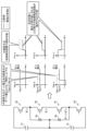
- FIG. 4 is the first diagram for explaining the control method in the drive circuit according to the first embodiment.
- the left side of FIG. 4 shows a situation in which the outer element 5a turns on when the inner elements 5b and 5c are on in a power conversion circuit section for one phase.
- the right side of FIG. 4 shows the operating waveforms of the gate voltage Vge and the collector voltage Vce in this situation.
- the horizontal axis is time.
- the subscripts a, b, and c correspond to the subscripts of the semiconductor elements 5, for example, "Vge_a” means the gate voltage Vge of the outer element 5a, and "Vce_b” means the collector voltage Vce of the inner element 5b.
- the solid lines show the operating waveforms according to the comparative example, and the dashed lines show the operating waveforms according to the control method of the first embodiment.
- the gate voltage Vge_a applied to the outer element 5a is controlled to be lower than the gate voltages Vge_b, Vge_c applied to the inner elements 5b, 5c.
- the outer element 5a and the inner elements 5b, 5c are not distinguished from each other, and a specified voltage, which is a predetermined gate voltage when the semiconductor element 5 is on, is applied when the semiconductor element 5 is turned on. That is, in the comparative example, a specified voltage is applied uniformly when the semiconductor element 5 is turned on, whereas in embodiment 1, a gate voltage Vge_a lower than the specified voltage is applied to the outer element 5a when the outer element 5a is turned on.
- the above-mentioned specified voltage does not need to be a constant fixed voltage, but may be a variable voltage from which several set voltages can be selected. Therefore, when the gate voltages Vge_b and Vge_c applied when turning on the inner elements 5b and 5c are a first voltage, the control unit 4a that controls the drive of the outer element 5a performs control to apply a second voltage lower than the first voltage when turning on the outer element 5a.
- the gate voltage Vge_d applied to the outer element 5d is controlled to be lower than the gate voltages Vge_b and Vge_c applied to the inner elements 5b and 5c. This control allows the short circuit detection circuit 3 connected to the outer element 5d to detect an arm short circuit in the power conversion circuit, making it possible to ensure reliable implementation of short circuit protection operation while suppressing the generation of excessive surge voltage.
- FIG. 5 is a second diagram for explaining the control method in the drive circuit according to the first embodiment. While FIG. 4 is a diagram showing the operation when the outer element 5a is turned on, FIG. 5 is a diagram showing the operation when the inner element 5c is turned on. Note that the notations, the distinctions of the line types, and the meanings of the comparative examples are the same as those in FIG. 4.
- the outer element 5a in the on state is driven by the application of a gate voltage Vge_a that is lower than a specified voltage when turned on, and this gate voltage Vge_a is maintained even in the on state.
- the inner element 5b in the on state is driven by the application of a gate voltage Vge_b that is a specified voltage when turned on, and this gate voltage Vge_b is maintained even in the on state.
- the inner element 5c that turns on is applied with a gate voltage Vge_c that is a specified voltage.
- the collector voltage Vce_a of the outer element 5a and the collector voltages Vce_b and Vce_c of the inner elements 5b and 5c are divided by the on-resistance of each element. Therefore, similar to the example in FIG. 4, the voltage is divided almost equally between the elements, so it is unclear which element's short circuit detection circuit 3 will operate. This results in an uncertain state as to which element will perform the turn-off operation, and if the inner elements 5b and 5c turn off first, there is a risk of an excessive surge voltage being generated.
- the semiconductor element drive circuit includes a control unit that individually controls one of the four semiconductor elements connected in series that constitute one phase of the power conversion circuit unit of the three-level power converter, and applies a gate voltage to the semiconductor element to drive the semiconductor element.
- the semiconductor element drive circuit detects an arm short circuit in the power conversion circuit unit based on the main terminal voltage of the semiconductor element.
- each control unit that controls the drive of the higher potential side outer element and the lower potential side outer element of the four semiconductor elements applies a gate voltage lower than a specified voltage to the semiconductor element when turning on the semiconductor element.
- an arm short circuit in the power conversion circuit unit is detected by the short circuit detection circuit connected to the outer element, so that the outer element can be turned off first. This makes it possible to obtain a drive circuit that can ensure reliable implementation of short circuit protection operation while suppressing the generation of excessive surge voltage.
- each control unit that controls the drive of the upper potential side inner element and the lower potential side inner element may be configured to apply a first voltage as a gate voltage when turning on the semiconductor element
- each control unit that controls the drive of the upper potential side outer element and the lower potential side outer element may be configured to apply a second voltage lower than the first voltage as a gate voltage when turning on the semiconductor element.
- Embodiment 2. 6 is a schematic circuit diagram for explaining the connection relationship between the driving device according to the second embodiment and the semiconductor element to be driven.
- the driving device 100 according to the second embodiment includes an integrated control unit 8 and four driving circuits 50a1, 50b1, 50c1, and 50d1.
- the driving circuit 50a1 drives the semiconductor element 5a
- the driving circuit 50b1 drives the semiconductor element 5b
- the driving circuit 50c1 drives the semiconductor element 5c
- the driving circuit 50d1 drives the semiconductor element 5d.
- Each driving circuit 50 includes a gate driving circuit 2 and a short circuit detection circuit 3, as in the first embodiment.
- control unit 4 included in each driving circuit 50 is configured to control one semiconductor element 5 to be controlled, but in the second embodiment, the integrated control unit 8 is configured to collectively control the four semiconductor elements 5a to 5d.
- Other configurations are the same or equivalent to those of the first embodiment shown in FIG. 1, and the same or equivalent components are designated by the same reference numerals and redundant explanations will be omitted.
- FIG. 7 is a diagram used to explain a first example of a control method in a drive device according to embodiment 2.
- the left side of FIG. 7 shows a situation in which, in a power conversion circuit section for one phase, when the outer element 5a and the inner element 5b are in the on state, the inner element 5c turns on.
- the right side of FIG. 7 shows the operating waveforms of the gate voltage Vge and the collector voltage Vce in this situation. Note that the symbol notation, the distinction between the line types, and the meanings of the comparative examples are the same as in FIG. 5.
- the operating waveforms in the comparative example are the same as or equivalent to those shown in FIG. 5. That is, as in the example of FIG. 5, voltage is divided almost evenly between each element, and it is unclear which element's short circuit detection circuit 3 will operate. Therefore, it is unclear which element will perform the turn-off operation, and if the inner elements 5b and 5c turn off first, there is a risk of an excessive surge voltage being generated.
- the gate voltage Vge_a of the outer element 5a in the on state is temporarily lowered to a gate voltage Vge_a1 that is lower than the specified voltage.
- this control is appropriately referred to as the "first control.”
- the gate voltage Vge_a of the outer element 5a is returned to its original voltage, i.e., the specified voltage Vge_0, after a specified time has elapsed.
- the specified time can be determined according to the characteristics of the semiconductor element 5. For example, the specified time can be determined by setting an appropriate margin based on the time from when a turn-on command is issued to the inner element 5c to just after the gate voltage Vge_c of the inner element 5c exceeds the mirror voltage.
- the first control is implemented when the inner element 5c is turned on while the outer element 5a and the inner element 5b are in the on state.
- the first control is also implemented when the outer element 5a is turned on while the inner elements 5b and 5c are in the on state. That is, when the outer element 5a is turned on while the inner elements 5b and 5c are in the on state, the first control is implemented to temporarily lower the gate voltage applied to the outer element 5a to a voltage lower than the specified voltage.
- the arm short circuit of the power conversion circuit unit is detected by the short circuit detection circuit 3 connected to the outer element 5a, so that the outer element 5a can be turned off first, making it possible to ensure reliable implementation of the short circuit protection operation while suppressing the generation of excessive surge voltage.
- FIG. 8 is a diagram for explaining a second example of a control method in a drive device according to embodiment 2.
- the left side of FIG. 8 shows a situation in which, in a power conversion circuit section for one phase, the inner element 5b turns on when the inner element 5c and the outer element 5d are in the on state.
- the right side of FIG. 8 shows the operating waveforms of the gate voltage Vge and the collector voltage Vce in this situation. Note that the notation of symbols, the distinction of line types, and the meanings of comparative examples are the same as in FIG. 7.
- the operating waveforms in the comparative example are equivalent to those shown in FIG. 7. That is, as in the example of FIG. 7, voltage is divided almost equally between each element, and it is unclear which element's short circuit detection circuit 3 will operate. Therefore, it is unclear which element will perform the turn-off operation, and if the inner elements 5b and 5c turn off first, an excessive surge voltage may occur.
- the gate voltage Vge_d of the outer element 5d in the on state is temporarily lowered to a gate voltage Vge_d1 that is lower than the specified voltage.
- this control is appropriately referred to as the "second control.”
- the gate voltage Vge_d of the outer element 5d is returned to its original voltage, i.e., the specified voltage Vge_0, after the specified time has elapsed.
- the specified time can be determined according to the characteristics of the semiconductor element 5, as explained in the example of FIG. 7.
- the second control is implemented when the inner element 5b is turned on while the inner element 5c and the outer element 5d are in the on state.
- the second control is also implemented when the outer element 5d is turned on while the inner elements 5b and 5c are in the on state. That is, when the outer element 5d is turned on while the inner elements 5b and 5c are in the on state, the second control is implemented to temporarily lower the gate voltage applied to the outer element 5d to a voltage lower than the specified voltage.
- the arm short circuit of the power conversion circuit unit is detected by the short circuit detection circuit 3 connected to the outer element 5d, so that the outer element 5d can be turned off first, making it possible to ensure reliable implementation of the short circuit protection operation while suppressing the generation of excessive surge voltage.
- FIG. 9 is a diagram for explaining a third example of a control method in a drive device according to embodiment 2.
- the left side of FIG. 9 shows a situation in which, in a power conversion circuit section for one phase, when the outer element 5a and the inner element 5b are in the on state, the inner element 5c turns on.
- the right side of FIG. 9 shows the operating waveforms of the gate voltage Vge and the collector voltage Vce in this situation. Note that the notation of symbols, the distinction of line types, and the meanings of comparative examples are the same as in FIG. 7.
- the operating waveforms in the comparative example are equivalent to those shown in FIG. 7. That is, as in the example of FIG. 7, voltage is divided almost equally between each element, and it is unclear which element's short circuit detection circuit 3 will operate. Therefore, it is unclear which element will perform the turn-off operation, and if the inner elements 5b and 5c turn off first, an excessive surge voltage may occur.
- the gate voltage Vge_b of the inner element 5b in the on state is temporarily increased to a gate voltage Vge_b1 higher than the specified voltage
- the gate voltage Vge_c of the inner element 5c to be turned on is temporarily increased to a gate voltage Vge_c1 higher than the specified voltage.
- this control is appropriately called "third control”. Note that the gate voltage Vge_b1 and the gate voltage Vge_c1 may be the same voltage.
- the gate voltage Vge_b of the inner element 5b and the gate voltage Vge_c of the inner element 5c are returned to the original voltage, that is, the specified voltage Vge_0, after the specified time has elapsed.
- the specified time can be determined according to the characteristics of the semiconductor element 5, as described in the examples of FIG. 7 and FIG. 8.
- a third example of the control method of embodiment 2 voltage sharing is performed so that a larger divided voltage is generated in the outer element 5a to which a relatively low gate voltage Vge_a is applied.
- the arm short circuit of the power conversion circuit unit is detected by the short circuit detection circuit 3 connected to the outer element 5a, so that the outer element 5a can be turned off first, and it is possible to ensure reliable implementation of short circuit protection operation while suppressing the occurrence of excessive surge voltage, as in the examples of Figures 7 and 8.
- the third control is implemented when the inner element 5c is turned on while the outer element 5a and the inner element 5b are in the on state.
- the third control is also implemented when the outer element 5a is turned on while the inner elements 5b and 5c are in the on state. That is, when the outer element 5a is turned on while the inner elements 5b and 5c are in the on state, the third control is implemented to temporarily increase the gate voltage applied to the inner elements 5b and 5c to a voltage higher than the specified voltage.
- the arm short circuit of the power conversion circuit unit is detected by the short circuit detection circuit 3 connected to the outer element 5a, so that the outer element 5a can be turned off first, and it is possible to ensure reliable implementation of the short circuit protection operation while suppressing the generation of excessive surge voltage.
- the third control is also implemented when the inner element 5b is turned on. That is, when the inner element 5c and the outer element 5d are in the on state and the inner element 5b is turned on, the third control is implemented to temporarily increase the gate voltage applied to the inner elements 5b, 5c to a voltage higher than the specified voltage. Even in this case, the arm short circuit of the power conversion circuit unit is detected by the short circuit detection circuit 3 connected to the outer element 5d, so that the outer element 5d can be turned off first, making it possible to ensure reliable implementation of the short circuit protection operation while suppressing the generation of excessive surge voltage.
- the third control is also implemented when the outer element 5d is turned on while the inner elements 5b and 5c are on. That is, when the outer element 5d is turned on while the inner elements 5b and 5c are on, the third control is implemented to temporarily increase the gate voltage applied to the inner elements 5b and 5c to a voltage higher than the specified voltage. Even in this case, the arm short circuit of the power conversion circuit unit is detected by the short circuit detection circuit 3 connected to the outer element 5d, so that the outer element 5d can be turned off first, making it possible to ensure reliable implementation of the short circuit protection operation while suppressing the generation of excessive surge voltage.
- FIG. 10 is a diagram showing, in table form, the main points of the first to third examples of the control method in the drive device of embodiment 2.
- the upper part of FIG. 10 shows the elements that are in the on state, the elements that are turned on, and the elements that lower the gate voltage when lowering the gate voltage Vge_a of the outer element 5a and the gate voltage Vge_d of the outer element 5d shown in FIG. 7 and FIG. 8.
- the first row from the top of FIG. 10 corresponds to FIG. 7, and the fourth row from the top of FIG. 10 corresponds to FIG. 8.
- the fourth row from the bottom of FIG. 10 corresponds to FIG. 9.
- the semiconductor element drive device includes a general control unit that controls the operation of four gate drive circuits that individually drive one of four semiconductor elements consisting of a higher potential side outer element, a higher potential side inner element, a lower potential side inner element, and a lower potential side outer element that are connected in series and that constitute a power conversion circuit section for one phase of a three-level power converter.
- the semiconductor element drive device detects an arm short circuit in the power conversion circuit section based on the main terminal voltage of the semiconductor element.
- the general control unit performs a first control to temporarily lower the gate voltage applied to the higher potential side outer element to a voltage lower than a specified voltage.
- the general control unit performs a second control to temporarily lower the gate voltage applied to the lower potential side outer element to a voltage lower than a specified voltage.
- the short circuit detection circuit connected to the outer element detects an arm short circuit in the power conversion circuit, and the outer element can be turned off first. This makes it possible to obtain a drive device that can ensure reliable implementation of short circuit protection operation while suppressing the generation of excessive surge voltage.
- the first control may be performed when the lower potential side inner element is turned on when the higher potential side outer element and the higher potential side inner element are both on.
- the first control may be performed when the higher potential side outer element is turned on when the higher potential side inner element and the lower potential side inner element are both on.
- the second control may be performed when the lower potential side outer element is turned on when the higher potential side inner element and the lower potential side inner element are both in the on state.
- the second control may be performed when the higher potential side inner element is turned on when the lower potential side inner element and the lower potential side outer element are both in the on state.
- the semiconductor element driving device includes a general control unit that controls the operation of four gate driving circuits that individually drive one of four semiconductor elements consisting of a higher potential side outer element, a higher potential side inner element, a lower potential side inner element, and a lower potential side outer element that are connected in series and that constitute a power conversion circuit section for one phase of a three-level power converter.
- the semiconductor element driving device detects an arm short circuit in the power conversion circuit section based on the main terminal voltage of the semiconductor element.
- the general control unit performs a third control that temporarily increases the gate voltage applied to the higher potential side inner element and the lower potential side inner element to a voltage higher than the specified voltage.
- an arm short circuit in the power conversion circuit section is detected by the short circuit detection circuit connected to the outer element, so that the outer element can be turned off first. This makes it possible to obtain a driving device that can ensure reliable implementation of short circuit protection operation while suppressing the generation of excessive surge voltage.
- the third control may be performed when the lower potential side inner element is turned on when the higher potential side outer element and the higher potential side inner element are both on.
- the third control may be performed when the higher potential side outer element is turned on or when the lower potential side outer element is turned on when the higher potential side inner element and the lower potential side inner element are both on.
- the third control may be performed when the higher potential side inner element is turned on when the lower potential side inner element and the lower potential side outer element are both on.
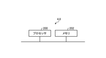
- FIG. 11 is a diagram showing an example of a hardware configuration for realizing the functions of the control unit 4 according to embodiment 1 and the overall control unit 8 according to embodiment 2.
- the functions of the control unit 4 and the overall control unit 8 are realized by the processor 200 and the memory 202.
- the processor 200 is a CPU (also called a Central Processing Unit, processing unit, arithmetic unit, microprocessor, microcomputer, processor, or DSP (Digital Signal Processor)) or a system LSI (Large Scale Integration).
- Examples of the memory 202 include non-volatile or volatile semiconductor memory such as RAM (Random Access Memory), ROM (Read Only Memory), flash memory, EPROM (Erasable Programmable Read Only Memory), and EEPROM (registered trademark) (Electrically Erasable Programmable Read Only Memory).
- the memory 202 stores a program that executes the functions of the control unit 4 according to the first embodiment or the general control unit 8 according to the second embodiment.
- the processor 200 reads the program stored in the memory 202 and runs the program, and can execute the above-mentioned processing by the processor 200 referring to the data stored in the memory 202.
- a separate controller 4 is provided for each drive circuit 50, but this is not a limitation.
- a central controller 8 similar to that in the second embodiment may be provided, and the central controller 8 may be connected to the individual gate drive circuits 2a-2d and the individual short circuit detection circuits 3a-3d, and the central controller 8 may control the operation of the four semiconductor elements 5a-5d.
Landscapes
- Engineering & Computer Science (AREA)
- Power Engineering (AREA)
- Power Conversion In General (AREA)
Priority Applications (3)
| Application Number | Priority Date | Filing Date | Title |
|---|---|---|---|
| DE112023005952.7T DE112023005952T5 (de) | 2023-03-10 | 2023-03-10 | Ansteuerschaltung und ansteuervorrichtung für halbleitervorrichtungen |
| JP2025506262A JP7745806B2 (ja) | 2023-03-10 | 2023-03-10 | 半導体素子の駆動回路 |
| PCT/JP2023/009437 WO2024189706A1 (ja) | 2023-03-10 | 2023-03-10 | 半導体素子の駆動回路及び駆動装置 |
Applications Claiming Priority (1)
| Application Number | Priority Date | Filing Date | Title |
|---|---|---|---|
| PCT/JP2023/009437 WO2024189706A1 (ja) | 2023-03-10 | 2023-03-10 | 半導体素子の駆動回路及び駆動装置 |
Publications (1)
| Publication Number | Publication Date |
|---|---|
| WO2024189706A1 true WO2024189706A1 (ja) | 2024-09-19 |
Family
ID=92754677
Family Applications (1)
| Application Number | Title | Priority Date | Filing Date |
|---|---|---|---|
| PCT/JP2023/009437 Ceased WO2024189706A1 (ja) | 2023-03-10 | 2023-03-10 | 半導体素子の駆動回路及び駆動装置 |
Country Status (3)
| Country | Link |
|---|---|
| JP (1) | JP7745806B2 (https=) |
| DE (1) | DE112023005952T5 (https=) |
| WO (1) | WO2024189706A1 (https=) |
Citations (4)
| Publication number | Priority date | Publication date | Assignee | Title |
|---|---|---|---|---|
| JPH1066348A (ja) * | 1996-08-15 | 1998-03-06 | Fuji Electric Co Ltd | 3レベル電力変換器の短絡保護装置 |
| JP2010098820A (ja) * | 2008-10-15 | 2010-04-30 | Toshiba Corp | 電力変換装置 |
| US20150357935A1 (en) * | 2014-06-06 | 2015-12-10 | Delta Electronics (Shanghai) Co., Ltd. | Tnpc inverter device and method for detecting short-circuit thereof |
| JP2020182338A (ja) * | 2019-04-25 | 2020-11-05 | 株式会社Ihi | 半導体スイッチング素子駆動回路及びマルチレベル電力変換器 |
-
2023
- 2023-03-10 WO PCT/JP2023/009437 patent/WO2024189706A1/ja not_active Ceased
- 2023-03-10 JP JP2025506262A patent/JP7745806B2/ja active Active
- 2023-03-10 DE DE112023005952.7T patent/DE112023005952T5/de active Pending
Patent Citations (4)
| Publication number | Priority date | Publication date | Assignee | Title |
|---|---|---|---|---|
| JPH1066348A (ja) * | 1996-08-15 | 1998-03-06 | Fuji Electric Co Ltd | 3レベル電力変換器の短絡保護装置 |
| JP2010098820A (ja) * | 2008-10-15 | 2010-04-30 | Toshiba Corp | 電力変換装置 |
| US20150357935A1 (en) * | 2014-06-06 | 2015-12-10 | Delta Electronics (Shanghai) Co., Ltd. | Tnpc inverter device and method for detecting short-circuit thereof |
| JP2020182338A (ja) * | 2019-04-25 | 2020-11-05 | 株式会社Ihi | 半導体スイッチング素子駆動回路及びマルチレベル電力変換器 |
Also Published As
| Publication number | Publication date |
|---|---|
| JP7745806B2 (ja) | 2025-09-29 |
| DE112023005952T5 (de) | 2026-01-15 |
| JPWO2024189706A1 (https=) | 2024-09-19 |
Similar Documents
| Publication | Publication Date | Title |
|---|---|---|
| JP6819256B2 (ja) | 駆動回路及び該回路を含んでなる半導体モジュール | |
| JP2022093390A (ja) | 半導体装置 | |
| JP6086101B2 (ja) | 半導体装置 | |
| JP5751236B2 (ja) | スイッチング制御回路 | |
| JP2018011467A (ja) | 半導体スイッチング素子のゲート駆動回路 | |
| JP6887320B2 (ja) | 電力変換ユニットの駆動回路および駆動方法、電力変換ユニット、並びに電力変換装置 | |
| JP2017079534A (ja) | ゲート制御回路 | |
| JP4506276B2 (ja) | 自己消弧形半導体素子の駆動回路 | |
| JP7047898B2 (ja) | スイッチング装置及びスイッチング装置の制御方法 | |
| JPWO2020017169A1 (ja) | 駆動回路内蔵型パワーモジュール | |
| JP7745806B2 (ja) | 半導体素子の駆動回路 | |
| JP2020078213A (ja) | スイッチング素子制御回路 | |
| JP2001025259A (ja) | Pwmインバーター装置 | |
| US12476453B2 (en) | Electronic circuitry, method, computer program, and electronic system | |
| JP4675910B2 (ja) | インバータ装置 | |
| JP7814610B2 (ja) | 半導体素子の駆動回路 | |
| JP3325303B2 (ja) | 保護機能を備えたスイッチ装置 | |
| JP2020014315A (ja) | 半導体装置 | |
| JP2023136689A (ja) | スイッチング素子の駆動回路及びインテリジェントパワーモジュール | |
| JP4946103B2 (ja) | 電力変換装置 | |
| JP2009124781A (ja) | 電圧駆動型半導体素子のゲート駆動装置 | |
| WO2022153520A1 (ja) | 電力変換装置 | |
| US20230179199A1 (en) | Drive circuit | |
| JP7815627B2 (ja) | ブートストラップ回路、および半導体装置 | |
| WO2026042293A1 (ja) | ゲート駆動装置および電力変換装置 |
Legal Events
| Date | Code | Title | Description |
|---|---|---|---|
| 121 | Ep: the epo has been informed by wipo that ep was designated in this application |
Ref document number: 23927330 Country of ref document: EP Kind code of ref document: A1 |
|
| WWE | Wipo information: entry into national phase |
Ref document number: 2025506262 Country of ref document: JP |
|
| WWE | Wipo information: entry into national phase |
Ref document number: 202517081936 Country of ref document: IN |
|
| WWP | Wipo information: published in national office |
Ref document number: 202517081936 Country of ref document: IN |
|
| WWE | Wipo information: entry into national phase |
Ref document number: 112023005952 Country of ref document: DE |
|
| WWP | Wipo information: published in national office |
Ref document number: 112023005952 Country of ref document: DE |
|
| 122 | Ep: pct application non-entry in european phase |
Ref document number: 23927330 Country of ref document: EP Kind code of ref document: A1 |