WO2024185132A1 - 数値制御装置 - Google Patents
数値制御装置 Download PDFInfo
- Publication number
- WO2024185132A1 WO2024185132A1 PCT/JP2023/009072 JP2023009072W WO2024185132A1 WO 2024185132 A1 WO2024185132 A1 WO 2024185132A1 JP 2023009072 W JP2023009072 W JP 2023009072W WO 2024185132 A1 WO2024185132 A1 WO 2024185132A1
- Authority
- WO
- WIPO (PCT)
- Prior art keywords
- interference
- inter
- axis
- destination
- unit
- Prior art date
- Legal status (The legal status is an assumption and is not a legal conclusion. Google has not performed a legal analysis and makes no representation as to the accuracy of the status listed.)
- Ceased
Links
Images




















Classifications
-
- G—PHYSICS
- G05—CONTROLLING; REGULATING
- G05B—CONTROL OR REGULATING SYSTEMS IN GENERAL; FUNCTIONAL ELEMENTS OF SUCH SYSTEMS; MONITORING OR TESTING ARRANGEMENTS FOR SUCH SYSTEMS OR ELEMENTS
- G05B19/00—Program-control systems
- G05B19/02—Program-control systems electric
- G05B19/18—Numerical control [NC], i.e. automatically operating machines, in particular machine tools, e.g. in a manufacturing environment, so as to execute positioning, movement or co-ordinated operations by means of program data in numerical form
- G05B19/406—Numerical control [NC], i.e. automatically operating machines, in particular machine tools, e.g. in a manufacturing environment, so as to execute positioning, movement or co-ordinated operations by means of program data in numerical form characterised by monitoring or safety
- G05B19/4061—Avoiding collision or forbidden zones
-
- G—PHYSICS
- G05—CONTROLLING; REGULATING
- G05B—CONTROL OR REGULATING SYSTEMS IN GENERAL; FUNCTIONAL ELEMENTS OF SUCH SYSTEMS; MONITORING OR TESTING ARRANGEMENTS FOR SUCH SYSTEMS OR ELEMENTS
- G05B2219/00—Program-control systems
- G05B2219/30—Nc systems
- G05B2219/39—Robotics, robotics to robotics hand
- G05B2219/39096—Self-collision, internal collison, collision between links of one robot
-
- G—PHYSICS
- G05—CONTROLLING; REGULATING
- G05B—CONTROL OR REGULATING SYSTEMS IN GENERAL; FUNCTIONAL ELEMENTS OF SUCH SYSTEMS; MONITORING OR TESTING ARRANGEMENTS FOR SUCH SYSTEMS OR ELEMENTS
- G05B2219/00—Program-control systems
- G05B2219/30—Nc systems
- G05B2219/49—Nc machine tool, till multiple
- G05B2219/49153—Avoid collision, interference between tools moving along same axis
Definitions
- This disclosure relates to a numerical control device.
- Patent Document 1 describes this type of technology.
- This disclosure has been made in consideration of the above problems, and aims to provide technology that can efficiently avoid interference with interfering objects in a numerical control device that controls a machine.
- the present disclosure relates to a numerical control device that includes a graph generation unit that generates a mechanical configuration of a controlled object in a graph format, a control point coordinate system insertion unit that inserts a control point and a coordinate system into the mechanical configuration in the graph format, an inter-element condition setting unit that sets the shape of an interfering object in an inter-element relationship as an inter-element condition that must be satisfied by the relationship between a first element that is a first control point and a second element that is a second control point, an inter-element relationship output unit that outputs an interference condition equation for preventing interference by the interfering object based on the inter-element condition set in the inter-element relationship, and an inter-element relationship control unit that controls the inter-element relationship based on the inter-element relationship and the interference condition equation.
- This disclosure provides technology that can efficiently avoid interference with interfering objects in a numerical control device that controls a machine.
- FIG. 1 is a diagram illustrating an example of the configuration of a numerical control device according to an embodiment of the present invention.
- 2 is a functional block diagram of a CPU (control unit) included in the numerical control device according to the embodiment of the present invention.
- FIG. FIG. 2 is a schematic diagram showing an example of a relationship between a tool and a workpiece according to an embodiment of the present invention.
- 5A to 5C are schematic diagrams illustrating an example of interference by an interfering object according to an embodiment of the present invention.
- 5 is a flowchart showing an obstacle avoidance control according to an embodiment of the present invention.
- 10 is a schematic diagram showing an example of a positional relationship of an interfering object based on a movement command;
- FIG. 13 is a schematic diagram showing the destinations of each axis when interference is avoided in an interpolation unit. 10 is a schematic diagram showing an example of a positional relationship of an interfering object based on a movement command; FIG. 13 is a schematic diagram showing the movement destinations of each axis when interference is avoided in block units.
- FIG. 2 is a schematic diagram showing an example of a relationship between a tool and a workpiece according to an embodiment of the present invention.
- 5A to 5C are schematic diagrams illustrating an example of interference by an interfering object according to an embodiment of the present invention.
- FIG. 13 is a schematic diagram showing how interference is detected.
- FIG. 11 is a schematic diagram showing an operation for avoiding interference.
- FIG. 13 is a schematic diagram showing how interference is avoided.
- FIG. 13 is a schematic diagram showing a normal operation after escaping interference.
- FIG. 2 is a schematic diagram showing an example of a relationship between a tool and a workpiece according to an embodiment of the present invention.
- 11A and 11B are schematic diagrams showing an example of interference between a tool and a workpiece;
- 11 is a schematic diagram showing the relationship between the movement to avoid an obstacle and mathematical expressions;
- FIG. FIG. 2 is a schematic diagram showing an example of a relationship between a tool and a workpiece according to an embodiment of the present invention.
- 5A to 5C are schematic diagrams illustrating an example of interference by an interfering object according to an embodiment of the present invention.
- FIG. 4 is a schematic diagram showing the separation axis direction of an interfering object.
- FIG. 11 is a schematic diagram showing the positional relationship of an interfering object in the coordinate system of the root node;
- FIG. 4 is a schematic diagram showing the positional relationship of an interfering object in a motor coordinate system;
- FIG. 11A and 11B are schematic diagrams showing how interference is detected in an operation based on a command position;
- FIG. 13 is a schematic diagram showing a state in which an avoidance movement is started.
- 11A and 11B are schematic diagrams showing the destinations of each axis when interference is avoided.
- 11 is a schematic diagram showing the relationship between a command and an interfering object before interference is avoided by a separate shaft;
- FIG. FIG. 2 is a schematic diagram showing interference avoidance by a separate shaft 1.
- FIG. 2 is a schematic diagram showing interference avoidance by a separate shaft 2.
- FIG. 13 is a schematic diagram showing interference avoidance by a separation shaft 3.
- FIG. 13 is a schematic diagram showing a return to a command position.
- FIG. 4 is a schematic diagram showing the relationship between each axis and a movable range.
- 5 is a schematic diagram showing the relationship between motor coordinate values and a movable range.
- FIG. 11A and 11B are schematic diagrams showing unnecessary movement that occurs in the relationship between motor coordinate values and a movable range.
- 11 is a schematic diagram showing how unnecessary movement is avoided in relation to the motor coordinate value and the movable range.
- FIG. FIG. 2 is a schematic diagram showing an example of a relationship between a tool and a workpiece according to an embodiment of the present invention.
- FIG. 10 is a schematic diagram showing how interference between an interfering object A and an interfering object B1 is detected;
- FIG. 10 is a schematic diagram showing how interference between an interfering object A and an interfering object B2 is detected;
- FIG. 11 is a schematic diagram showing the positional relationship of an interfering object in the coordinate system of the root node;
- FIG. 4 is a schematic diagram showing the positional relationship of an interfering object in a motor coordinate system;
- FIG. 10 is a schematic diagram showing how interference of a separation shaft 1 is detected.
- FIG. 13 is a schematic diagram showing a state in which interference of a separation shaft 2 is detected while interference of a separation shaft 1 is being avoided;
- FIG. 13 is a schematic diagram showing a state in which interference of a separation shaft 1 is detected after interference detection of a separation shaft 2 has been released;
- FIG. 13 is a schematic diagram showing a state in which interference of a separation shaft 3 is detected after interference detection of a separation shaft 1 has been lost;
- FIG. 13 is a schematic diagram showing a state in which interference detection of a separation shaft 3 is released.
- FIG. FIG. 2 is a schematic diagram showing how an actual movement corresponds to a movement command;
- 2 is a functional block diagram of a CPU (control unit) included in the numerical control device according to the embodiment of the present invention.
- FIG. 5 is a flowchart showing an obstacle avoidance control according to an embodiment of the present invention.
- 13A and 13B are diagrams illustrating examples of coordinates of destinations of movement on each axis before and after correction.
- 11 is a schematic diagram showing the movement destinations of each axis and the positional relationship between the tool and the workpiece before and after correction.
- FIG. 2 is a functional block diagram of a CPU (control unit) included in the numerical control device according to the embodiment of the present invention.
- FIG. FIG. 1 is a schematic diagram illustrating a separation axis method for a polyhedron having a plurality of convex shapes.
- FIG. 13 is a schematic diagram showing an example of calculation of a separation axis based on the cross product of each side of a convex polyhedron A and each side of a convex polyhedron B.
- FIG. 13 is a schematic diagram showing an example of calculation of a separation axis based on the normal direction of each surface.
- FIG. 10A to 10C are schematic diagrams showing examples of avoidance operations that differ depending on the shape of an obstruction.
- FIG. 1 is a schematic diagram showing an example of an avoidance operation in a numerical control device of the prior art
- 5A to 5C are schematic diagrams showing an example of an avoidance operation in the numerical control device of the present embodiment.
- [Basic configuration] 1 shows an example of the configuration of a numerical control device 100 according to an embodiment of the present invention.
- the numerical control device 100 mainly includes a CPU 11, a ROM 12, a RAM 13, a CMOS memory 14, interfaces 15, 18, and 19, a PMC (programmable machine controller) 16, an I/O unit 17, axis control circuits 30 to 34, servo amplifiers 40 to 44, a spindle control circuit 60, and a spindle amplifier 61.
- the CPU 11 is a processor that controls the entire numerical control device 100.
- the CPU 11 reads the system program stored in the ROM 12 via the bus 20, and controls the entire numerical control device 100 according to the system program.
- RAM 13 stores temporary calculation data, display data, and various data entered by the operator via the display/MDI unit 70.
- the CMOS memory 14 is backed up by a battery (not shown) and is configured as a non-volatile memory that retains its stored state even when the power to the numerical control device 100 is turned off.
- the CMOS memory 14 stores machining programs loaded via the interface 15 and machining programs input via the display/MDI unit 70.
- ROM 12 is preloaded with various system programs for performing the edit mode processing required for creating and editing machining programs and for automatic operation processing.
- machining programs such as the machining program for implementing the present invention, can be input via the interface 15 or the display/MDI unit 70 and stored in the CMOS memory 14.
- the interface 15 allows the numerical control device 100 to be connected to an external device 72 such as an adapter. Machining programs and various parameters are read from the external device 72. In addition, machining programs edited within the numerical control device 100 can be stored in an external storage means via the external device 72.
- the PMC (Programmable Machine Controller) 16 is a sequence program built into the numerical control device 100 that outputs signals to the auxiliary devices of the machine tool (for example, actuators such as a robot hand for tool replacement) via the I/O unit 17 to control them. It also receives signals from various switches on an operation panel installed on the main body of the machine tool, performs the necessary signal processing, and then passes the signals to the CPU 11.
- the display/MDI unit 70 is a manual data input device equipped with a display, keyboard, etc.
- the interface 18 receives commands and data from the keyboard of the display/MDI unit 70 and passes them to the CPU 11.
- the interface 19 is connected to an operation panel 71 equipped with a manual pulse generator, etc.
- the axis control circuits 30-34 of each axis receive the movement command amount for each axis from the CPU 11 and output the command for each axis to the servo amplifiers 40-44.
- the servo amplifiers 40-44 receive this command and drive the servo motors 50-54 for each axis.
- the servo motors 50-54 for each axis have built-in position and speed detectors, and feed back position and speed feedback signals from these position and speed detectors to the axis control circuits 30-34, performing position and speed feedback control. Note that the position and speed feedback is omitted from the block diagram.
- the spindle control circuit 60 receives a spindle rotation command for the machine tool and outputs a spindle speed signal to the spindle amplifier 61.
- the spindle amplifier 61 receives this spindle speed signal and rotates the spindle motor 62 of the machine tool at the commanded rotation speed to drive the tool.
- a pulse encoder 63 is connected to the spindle motor 62 via gears or a belt.
- the pulse encoder 63 outputs a feedback pulse in synchronization with the rotation of the spindle.
- the feedback pulse is read by the CPU 11 via the bus 20.
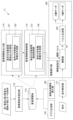
- FIG. 2 is a functional block diagram showing the functions that the above-mentioned CPU 11 (hereinafter also referred to as "control unit 11") performs by reading the system programs and application programs stored in ROM 12 via bus 20 and implementing them in accordance with the system programs and application programs.
- control unit 11 the above-mentioned CPU 11
- the CPU 11 includes a graph generation unit 101, a control point coordinate system insertion unit 102, a command analysis unit 111, an inter-element condition setting unit 112, an inter-element relationship output unit 114, an inter-element relationship control unit 115, a movement execution unit 140, and an interference check unit 150.
- the graph generating unit 101 generates the machine configuration of the controlled object in the form of a graph. An example of the generation of a machine configuration tree by the graph generating unit 101 will be described.
- the graph generating unit 101 first places an origin and multiple nodes. At this stage, there is no connection between the origin and multiple nodes, and the names of the origin and each node have not been set. Next, the graph generating unit 101 sets the axis name (axis type) of each axis of the machine configuration, the name of each tool, the name of each workpiece, the name of each origin, and the physical axis number (axis type) of each axis.
- the graph generating unit 101 sets the parent node (axis type) of each axis, the parent node of each tool, and the parent node of each workpiece. Finally, the graph generating unit 101 sets the cross offset (axis type) of each axis, the cross offset of each tool, and the cross offset of each workpiece.
- the control point coordinate system insertion unit 102 inserts a control point and a coordinate system into the graph of the machine configuration. An example of inserting a control point by the control point coordinate system insertion unit 102 will be described.
- the control point coordinate system insertion unit 102 specifies various positions on the machine configuration as control points and sets coordinate systems for various locations on the machine configuration. For example, it automatically inserts a coordinate system and a control point into each of the machine origin, multiple axes, and workpiece.
- the control point coordinate system insertion unit 102 performs automatic insertion not only for the table, but also for a series of nodes connected from each tool to the machine origin, that is, for all axes and tools.
- corresponding control points and coordinate systems are automatically inserted into all nodes that make up the machine configuration tree.
- a coordinate system is specified for the workpiece and a tool is specified as a control point. This makes it possible to handle various cases, such as when you want to specify a control point for the workpiece in order to move the workpiece itself to a specified position, or when you want to set a coordinate system for a tool itself in order to polish another tool with a tool.
- each control point and coordinate system may have an offset. This makes it possible to set a point away from the center of the node as the control point or coordinate system origin.
- each control point and coordinate system has an attitude matrix. If this attitude matrix is the attitude matrix of a control point, it represents the attitude (direction, inclination) of the control point, and if it is the attitude matrix of a coordinate system, it represents the attitude of the coordinate system.
- the offset and attitude matrix are expressed in a form linked to the corresponding node.
- each control point and coordinate system has information on whether or not to take into account the "movement" and "cross offset" of the nodes on the path to the root of the mechanical configuration tree, and these can be set.
- the command analysis unit 111 reads out and analyzes the numerical control program stored in the CMOS memory 14 for each block, and generates movement command data that commands the movement of each control axis of the machine tool based on the analysis results.
- the command analysis unit 111 transmits the generated movement command data to the movement execution unit 140.
- the inter-element condition setting unit 112 sets the first control point as the first element, sets the second control point as the second element, and sets the inter-element relationship between the first element and the second element. Note that the "first element” and the “second element” are not limited to control points.
- the inter-element condition setting unit 112 also accepts the shape of the interfering object as a condition that the relationship between the first element and the second element must satisfy, and sets this in the inter-element relationship 113.
- the condition that the relationship between the first element and the second element must satisfy is the shape of the interfering object.
- interfering objects are elements that make up a machine tool, and include various items such as jigs, tool holders, and tool changers.
- the inter-element relationship output unit 114 calculates a relationship output from the relationship between the first element and the second element.
- the inter-element relationship output unit 114 includes a conditional inter-element relationship output unit 121 that generates an interference condition equation for preventing interference by an interfering object based on the inter-element condition set in the inter-element relationship 113.
- the inter-element relationship control unit 115 outputs data for setting an interference condition equation to the movement execution unit 140 based on the relationship output.
- the inter-element relationship control unit 115 of this embodiment includes a conditional inter-element relationship control unit 131 that outputs the movement destination of each axis based on the inter-element relationship 113 and a condition equation for preventing interference by an interfering object.
- the movement execution unit 140 determines the movement command amount based on the analysis results and drives the servo motors 50 to 54 (X-axis servo, Y-axis servo, etc.) of each axis.
- the movement execution unit 140 of this embodiment includes an interpolation unit 141 and a pulse generation unit 142.
- the interpolation unit 141 executes an interpolation process to generate interpolation data by performing an interpolation calculation of points on a command path at a predetermined interpolation period based on the movement command data sent from the command analysis unit 111 and the data setting the movement destination of each axis sent from the inter-element relationship control unit 115.
- the interpolation unit 141 transmits the generated interpolation data to the pulse generation unit 142.
- the pulse generating unit 142 generates movement commands for the machine tool, i.e., movement pulses for each servo motor 50-54 (X-axis servo, Y-axis servo, etc.) of the machine tool, for each of the above-mentioned interpolation periods based on the interpolation data sent from the interpolating unit 141.
- the pulse generating unit 142 inputs the movement pulses generated as described above to the servo motors 50-54, thereby moving multiple mechanical elements of the machine tool along multiple control axes.
- the interference check unit 150 executes a process to determine whether interference will occur between the multiple mechanical elements that make up the machine tool when the movement pulses generated by the pulse generation unit 142 are continuously input to the servo motors 50-54.
- the interference check unit 150 determines the possibility of interference, for example, by performing an interference check calculation on multiple check target pairs.
- a check target pair is formed by combining two of the multiple mechanical elements that make up the machine tool. If the total number of mechanical elements that make up the machine tool is N, the total number of check target pairs is N(N-1)/2.
- the interference check calculation is performed based on a known interference check algorithm (for example, the split axis method).
- Fig. 3 is a schematic diagram showing an example of the relationship between a tool and a workpiece in an embodiment of the present invention.
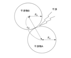
- Fig. 4 is a schematic diagram showing an example of interference of an interference object in an embodiment of the present invention.
- Figs. 3 and 4 show a spherical interference object A linked to a node and a spherical interference object B linked to a node in a machine configuration of three orthogonal axes, the X-axis, the Y-axis, and the Z-axis.
- interference object A is linked to the root node
- interference object B is linked to the Z-axis node.
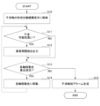
- FIG. 5 is a flowchart showing interference avoidance control in an embodiment of the present invention.
- the inter-element condition setting unit 112 stores the shape of the sphere in the mechanical configuration tree of the three orthogonal axes of the inter-element relationship 113.
- the inter-element condition setting unit 112 sets a spherical interference object A with a radius Ra at the root node and a spherical interference object B with a radius Rb at the Z node in the mechanical configuration tree of the inter-element relationship 113.
- step S11 the interference check unit 150 determines whether or not there is a high possibility of interference. If there is a high possibility of interference, the interference check unit 150 advances the process to step S12 (step S11; Yes). If there is a low possibility of interference, the interference check unit 150 advances the process to step S13 without going through step S12 (step S11; No).
- the conditional element relation output unit 121 outputs the element relation to the element relation control unit 115 based on the element condition set in the element relation 113.
- the conditional element relation output unit 121 outputs, for example, an equation representing an interference boundary between spheres as the element relation output.
- the interference boundary is a condition for an interfering object to be in contact with another object as shown in the following formula (1).
- r m indicates a motor coordinate value on the interference boundary
- Ra indicates the radius of the interfering object A
- Rb indicates the radius of the interfering object B (see Fig. 4).
- the conditional element relation output unit 121 assigns an interference boundary flag indicating that the element relation output is an interference boundary to the element relation output.
- step S13 the conditional element-to-element relation control unit 131 uses the element-to-element relation output (interference boundary) with the interference boundary flag set to ON as a constraint condition in the calculation of the destination of each axis. Specifically, the conditional element-to-element relation control unit 131 executes an inverse kinematics transformation with a constraint condition. In the inverse kinematics transformation, the destination of each axis is output based on the command coordinate value.
- the variables are defined as in the following formula (2).
- the vector r p in formula 2 is a variable indicating the command coordinate value (program coordinate system)
- the vector r m is a variable indicating the destination of each axis (motor coordinate system) in the case of avoidance
- the vector r mo is a variable indicating the destination of each axis (motor coordinate system) in the case of no avoidance.
- the above-mentioned constraint conditions are the inter-element relations (Formula 1) output by the conditional inter-element relation output unit 121.
- the value to be minimized is the square of the difference between the destination of each axis after avoidance and the destination of each axis before avoidance, and the value L to be minimized in the Lagrange undetermined multiplier method can be defined as in the following formula (3).
- Fig. 6A is a schematic diagram showing an example of the positional relationship of interfering objects based on a movement command.
- Fig. 6B is a schematic diagram showing the movement destinations of each axis when interference is avoided in interpolation units.
- interference may occur.
- One way to avoid this interference is to set the movement destination of each axis in interpolation units. Specifically, the movement destination of each axis is corrected in interpolation units using the following equation 8, which is obtained by solving equation 7.
- equation 8 is obtained by solving equation 7.
- Fig. 6B by correcting the movement destination of each axis in interpolation units, the movement direction changes in stages, and interference is avoided.
- FIG. 7A is a schematic diagram showing an example of the positional relationship of an interfering object based on a movement command. Even in the example shown in FIG. 7A, interference will occur if a machine tool is operated based on a movement command.
- One way to avoid this interference is to correct the destination of each axis on a block-by-block basis of the command from the command analysis unit 111. Specifically, the destination of each axis is corrected on a block-by-block basis using the following formula (9), which is obtained by solving formula 7.
- the inter-element relationship control unit 115 is configured to output information indicating each axis destination to the interpolation unit 141, but this configuration is not limited to this.
- the inter-element relationship control unit 115 may output information indicating each axis destination to the command analysis unit 111, and commands to avoid interference on a command block basis may be generated.
- FIG. 7B is a schematic diagram showing each axis destination when interference is avoided on a block basis. As shown in FIG. 7B, by correcting each axis destination on a block basis, the movement direction is set to a direction in which no interference will occur at the start of the movement, and interference is avoided.
- step S13 as described above, if the calculation of the destination of each axis is successful, the process proceeds to step S14 (step S13; Yes).
- step S14 the servo motors 50 to 54 are driven based on the calculated destination of each axis. If the calculation of the destination of each axis is not successful, the conditional inter-element relationship control unit 131 proceeds to step S15 for generating an interference detection alarm (step S13; No).
- step S15 a process is executed to generate an interference detection alarm to notify of interference by the display/MDI unit 70, an external computer (not shown), a sound device, etc.
- FIG. 8 is a schematic diagram showing an example of the relationship between the tool and the workpiece in an embodiment of the present invention.
- Fig. 9 is a schematic diagram showing an example of interference by an interfering object in an embodiment of the present invention.
- Figs. 8 and 9 show a rectangular parallelepiped interfering object A that is linked to a node and a rectangular parallelepiped interfering object B that is linked to a node in a machine configuration with three orthogonal axes, the X-axis, the Y-axis, and the Z-axis.
- the interfering object A is linked to the Y-axis
- the interfering object B is linked to the Z-axis node.
- the inter-element condition setting unit 112 sets the center and length and width of rectangular parallelepiped interfering object A in the Y-axis node, and the center and length and width of rectangular parallelepiped interfering object B in the Z-axis node as the shapes of the interfering objects in the inter-element relationship 113. Note that in this example, the only movable axis between interfering objects B and A is the Z-axis, so interference only occurs along the Z-axis.
- the conditional inter-element relation output unit 121 When interference between rectangular parallelepipeds is detected, the conditional inter-element relation output unit 121 outputs the following mathematical formula (10) which represents the interference boundary between the rectangular parallelepipeds. As described above, the interference axis is the z-axis. In mathematical formula (10), zm represents the motor coordinate value of the Z-axis which is the interference boundary, la represents the length of interfering object A in the z-axis direction, and lb represents the length of interfering object B in the z-axis direction (see FIG. 9). In addition, the conditional inter-element relation output unit 121 assigns an interference boundary flag which indicates that it is an interference boundary to the inter-element relation output.
- the conditional element relation control unit 131 executes an inverse kinematics transformation with constraint conditions applied using Lagrange's undetermined multiplier method, and outputs the destination of each axis.
- the variables are defined as in Equation 11.
- (1) is a variable indicating the destination of the control point (program coordinate system)
- (2) is a variable indicating the destination of each axis (motor coordinate system).
- K - 1 When a normal inverse kinematics transformation K - 1 is used for L in the Lagrange's undetermined multiplier method, the destination of each axis (motor coordinate system) can be expressed by the following Equation 12. Since Equation (12) assumes a cartesian three-axis machine, it becomes Equation 13.
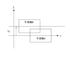
- FIG. 10A is a schematic diagram showing how interference is detected.
- the distance z p in the z-axis direction between the center of the interfering object A and the center of the interfering object B is shortened, and interference occurs.
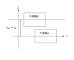
- FIG. 10B is a schematic diagram showing an operation to avoid interference.
- an avoidance operation is performed so that the distance in the z-axis direction between the center of the interfering object A and the center of the interfering object B becomes (l b +l a )/2p.
- FIG. 10C is a schematic diagram showing how interference is avoided when z p goes from a state where it satisfies the interference condition to a state where it does not satisfy the interference condition.
- escape from the interference area is performed so that the distance in the z-axis direction between the center of the interfering object A and the center of the interfering object B becomes longer than (l b +l a )/2p.
- FIG. 10D is a schematic diagram showing a normal operation after escaping from interference. In FIG. 10D, normal movement is shown occurring after escape.
- FIG. 11 is a schematic diagram showing an example of the relationship between the tool and the workpiece in an embodiment of the present invention.
- FIG. 12 is a schematic diagram showing an example of interference between the tool and the workpiece.
- FIG. 11 shows an example in which the workpiece is an interfering object A and the tool is an interfering object B in a machine configuration with three orthogonal axes, the X-axis, the Y-axis, and the Z-axis.
- the inter-element relationship that constrains the positional relationship between the workpiece element and the tool element is also shown.
- the interfering object A is a free-form surface workpiece that is linked to the workpiece node
- the interfering object B is a tool tip point that is linked to the tool node.
- FIG. 13 shows the state in which the tool tip of the tool comes into contact with the workpiece.
- the inter-element condition setting unit 112 sets a free-form surface interference object A on the work node and a point interference object B on the tool node.
- the inter-element condition setting unit 112 sets the free-form surface as a function of the following formula (16).
- conditional element relation output unit 121 When interference between the workpiece and the tool is detected, the conditional element relation output unit 121 outputs the following formula 17, which represents the interference boundary between the free-form surface of the workpiece and the tip point of the tool.
- the conditional element relation control unit 131 executes an inverse kinematics transformation with constraint conditions applied using the Lagrange undetermined multiplier method, and outputs the destination of each axis.
- the variables are the same as in the above-mentioned formula 11.
- L in the Lagrange undetermined multiplier method can be expressed by the following formula (18). Since formula (18) assumes a cartesian three-axis machine, it becomes formula (19).
- Fig. 13 is a schematic diagram showing the relationship between the movement to avoid an interfering object and mathematical expressions, which shows that the object is avoided at the closest point r m between f(x m , y m ) and r p .
- FIG. 14 is a schematic diagram showing an example of the relationship between a tool and a workpiece in an embodiment of the present invention.
- Fig. 15 is a schematic diagram showing an example of interference by an interfering object in an embodiment of the present invention.
- Figs. 14 and 15 show a rectangular parallelepiped interfering object A that is linked to a node and a rectangular parallelepiped interfering object B that is linked to a node in an arbitrary machine configuration.
- interfering object A is linked to the C-axis
- interfering object B is linked to the A-axis node.
- the inter-element condition setting unit 112 sets, for example, the position and shape of interfering object A (rectangular parallelepiped) linked to node C, and the position and shape of interfering object B (rectangular parallelepiped) linked to node A in the mechanical configuration tree of the inter-element relationship 113.
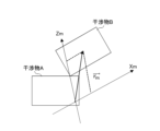
- FIG. 16 is a schematic diagram showing the separation axis direction of an interfering object.
- FIG. 16 shows interference detection by the separation axis method.
- the conditional inter-element relationship output unit 121 outputs the following formula (22) representing the interference boundary between the rectangular parallelepipeds.
- the vector r ab in formula (22) represents a vector from the center of interfering object A to the center of interfering object B (coordinate system of the root node).
- the vector l represents the separation axis direction (coordinate system of the root node)
- R a represents the radius of interfering object A in the separation axis direction
- R b represents the radius of interfering object B in the separation axis direction.
- the conditional inter-element relationship output unit 121 gives an interference boundary flag indicating that it is an interference boundary to the inter-element relationship control unit 115.
- the conditional element relation control unit 131 executes an inverse kinematics transformation with constraint conditions using the Lagrange undetermined multiplier method, and outputs the destination of each axis.
- the variables are the same as those in the above-mentioned formula 11.
- L in the Lagrange undetermined multiplier method can be expressed by the following formula (23).
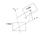
- Fig. 17A is a schematic diagram showing the positional relationship of an interfering object in the coordinate system of the root node.
- Fig. 17B is a schematic diagram showing the positional relationship of an interfering object in the motor coordinate system.
- Vector r a indicates the center position of the interfering object.
- Vector r ab can be expressed as the following formula (24) using a transformation matrix F from the motor coordinate system to the coordinate system of the root node and vector r m in the motor coordinate system, using a known technique for mechanical configuration trees.
- the conditional inter-element relation control unit 131 substitutes the equation indicating the vector r ab based on the equation (24) into the equation (23), and partially differentiates L with respect to (x m , y m , z m ), ⁇ .
- the equations (27) and (28) can be obtained.
- conditional inter-element relation control unit 131 obtains ⁇ based on formula (27) and formula (28).
- formula (27) is multiplied by matrix F from the left side and vector l from the right side to obtain formula (29).
- Formula (30) is obtained based on the obtained formula (29) and formula (28).
- Figure 18A is a schematic diagram showing how interference is detected in an operation based on a command position.
- Figure 18B is a schematic diagram showing how an avoidance movement is started.
- Figure 18C is a schematic diagram showing the destinations of each axis when interference is avoided.
- Fig. 19A is a schematic diagram showing the relationship between the command and the interfering object before the separation shaft avoids interference.
- Fig. 19A shows how interference occurs when moving based on the command.
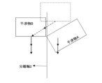
- Fig. 19B is a schematic diagram showing interference avoidance by separation shaft 1. As shown in Fig. 19B, before the occurrence of interference shown in Fig. 19A, separation shaft 1 is oriented in a direction parallel to the opposing surface of interfering object A, and interfering object B is moved.
- FIG. 19C is a schematic diagram showing interference avoidance by separation axis 2.
- the direction of separation axis 2 is set to a direction offset from the command direction, and interference A is moved.
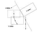
- FIG. 19D is a schematic diagram showing interference avoidance by separation axis 3.
- the direction of separation axis 3 is set to a direction parallel to the side surface adjacent to the opposing surface of interference A, and interference B is moved in a direction returning to the movement trajectory of the command value.
- FIG. 19E is a schematic diagram showing a return to the commanded position. As shown in FIG. 19E, interference B avoids interference A, returns to the same position as the position based on the command, and continues operation. Through this series of avoidance operations, interference between interference A and interference B can be avoided.
- FIG. 20 is a schematic diagram showing the relationship between each axis and the movable range.
- FIG. 21 is a schematic diagram showing the relationship between the motor coordinate value and the movable range.
- a movable range A1 of the X-axis, a movable range A2 of the Y-axis, and a movable range A3 of the Z-axis are set in an arbitrary mechanical configuration.
- the inter-element condition setting unit 112 sets the movable range of the points representing the coordinate values of each motor together with an arbitrary mechanical configuration as the shape of the interference object for the mechanical configuration tree of the inter-element relationship 113.
- conditional inter-element relation output unit 121 When interference caused by the motor coordinate value being outside the movable range is detected, the conditional inter-element relation output unit 121 outputs the following formula (32) which represents the interference boundary.
- xot represents the limit of the movable range of the xm axis.
- the conditional element relation control unit 131 executes an inverse kinematics transformation with constraint conditions using the Lagrange undetermined multiplier method, and outputs the destination of each axis.
- the variables are the same as in the above-mentioned formula (11).
- the vector r p in formula 11 that defines the variables indicates the destination of the control point (program coordinate system), and the vector r m indicates the destination of each axis (motor coordinate system).
- K -1 When a normal inverse kinematics transformation K -1 is used, L in the Lagrange undetermined multiplier method can be expressed by the following formula (33).
- the conditional inter-element relation control unit 131 partially differentiates L with respect to (x m , y m , z m ), ⁇ 1 , and ⁇ 2 to obtain formula (34).
- Formula (35) is obtained by solving formula (34).
- Formula (35) realizes the OT area intrusion avoidance function in any machine configuration.
- Example 6 of Obstacle Avoidance Control Next, an example of control for avoiding unnecessary movement during interference avoidance will be described in the above-mentioned fifth example of interference avoidance control. Note that the basic configuration is the same as in the fifth example of interference avoidance control.
- Fig. 22 is a schematic diagram showing unnecessary movement that occurs in the relationship between the motor coordinate value and the movable range.
- Fig. 22 shows a state in which unnecessary movement occurs in the xp direction during avoidance operation when the motor coordinate value is outside the movable range. Since movement only in the orthogonal axis may be dangerous, it is preferable to fix the coordinate value of the orthogonal axis by the command value.
- the conditional inter-element relation output unit 121 When interference caused by the motor coordinate value being outside the movable range is detected, the conditional inter-element relation output unit 121 outputs the following formula (32) which represents the interference boundary. As shown in the following formula (36), the actual movement is constrained to xp in order to prevent unintended movement in the xp direction by the avoidance operation. K in formula (36) represents a normal forward kinematics transformation process.
- the conditional element relation control unit 131 executes an inverse kinematics transformation with constraint conditions using the Lagrange undetermined multiplier method, and outputs the destination of each axis.
- the variables are the same as in the above-mentioned formula 11.
- the vector r p in formula 11 that defines the variables indicates the destination of the control point (program coordinate system), and the vector r m indicates the destination of each axis (motor coordinate system).
- K -1 When a normal inverse kinematics transformation K -1 is used, L in the Lagrange undetermined multiplier method can be expressed by the following formula (37). In this example, since a tilt three-axis machine is assumed, K -1 can be expressed by a matrix F as in formula (38), and formula (39) is obtained by substituting formula (38) into formula (37).
- each element of matrix F is set to formula (40), and L is partially differentiated with respect to (x m , y m , z m ), ⁇ 1 , and ⁇ 2 to obtain formula (41).
- Formula (41) is transformed into a form that can be solved by the numerical control device 100, resulting in formula (42).
- Fig. 23 is a schematic diagram showing the avoidance of unnecessary movement in the relationship between the motor coordinate value and the movable range.
- FIG. 24 is a schematic diagram showing an example of the relationship between a tool and a workpiece in an embodiment of the present invention.
- Fig. 25 is a schematic diagram showing an example of interference of an interfering object in an embodiment of the present invention.
- Figs. 24 and 25 show a rectangular interfering object A linked to a node, and multiple rectangular interfering objects B1 and B2 linked to the nodes in an arbitrary machine configuration.
- the interfering object A is linked to the C-axis node, and the interfering object B1 and the interfering object B2 are both linked to the A-axis node.
- the inter-element condition setting unit 112 sets the position and shape (rectangular parallelepiped) of interfering object A linked to the C-axis node, and the positions and shapes (rectangular parallelepipeds) of interfering objects B1 and B2 in the mechanical configuration tree of the inter-element relationship 113.
- FIG. 26A is a schematic diagram showing a state where interference between an interfering object A and an interfering object B1 is detected.
- the conditional inter-element relation output unit 121 outputs the following formula (43) which represents the interference boundary between the interfering object A and the interfering object B1.
- the vector r ab1 in formula (43) represents a vector (root node coordinate system) from the center of the interfering object A to the center of the interfering object B1.
- the vector l 1 represents the separation axis direction (root node coordinate system)
- R a1 represents the radius of the interfering object A in the separation axis direction
- R b1 represents the radius of the interfering object B1 in the separation axis direction.
- the conditional inter-element relation output unit 121 gives an interference boundary flag indicating that it is an interference boundary to the inter-element relation control unit 115.
- 26B is a schematic diagram showing a state where interference between an interfering object A and an interfering object B2 is detected.
- the conditional inter-element relationship output unit 121 detects interference with an interfering object B2 during an avoidance operation based on the interference boundary (inter-element output) of formula (43), it additionally outputs the interference boundary shown in formula (44).
- the vector r ab2 in formula (44) indicates a vector (root node coordinate system) from the center of the interfering object A to the center of the interfering object B2.
- the vector l 2 indicates the separation axis direction (root node coordinate system)
- R a2 indicates the radius of the interfering object A in the separation axis direction
- R b2 indicates the radius of the interfering object B2 in the separation axis direction.
- the conditional element relation control unit 131 executes an inverse kinematics transformation with constraint conditions using Lagrange's undetermined multipliers, and outputs the destination of each axis.
- the variables are the same as in the above-mentioned formula (11).
- L in the Lagrange's undetermined multiplier method can be expressed by the following formula (45).
- Fig. 27A is a schematic diagram showing the positional relationship of an interfering object in the coordinate system of the root node.
- Fig. 27B is a schematic diagram showing the positional relationship of an interfering object in the motor coordinate system.
- Vector r ab can be expressed as the following formula (46) using a transformation matrix F from the motor coordinate system to the coordinate system of the root node and vector r m in the motor coordinate system, using a known technique for mechanical configuration trees.
- the conditional inter-element relation control unit 131 substitutes the equation indicating the vector r ab based on equation (46) into equation (45), and partially differentiates L with respect to (x m , y m , z m ), ⁇ . Based on equations (25) and (26) in the above-mentioned example 4 of interference avoidance control, equations (47) and (48) can be obtained.
- conditional inter-element relation control unit 131 obtains ⁇ i based on formula (47) and formula (48).
- formula (47) is obtained by multiplying formula (47) from the left side by matrix F and multiplying it from the right side by vector l i .
- Formula (50) is obtained based on the obtained formula (49) and formula (48).
- Figure 28A is a schematic diagram showing how interference of separation shaft 1 is detected.
- Figure 28A shows a state in which interfering object A interferes with interfering object B1 when it moves based on a movement command.
- the interference avoidance operation by separation shaft 1 is initiated.
- FIG. 28B is a schematic diagram showing how interference with separation shaft 2 is detected while interference with separation shaft 1 is being avoided.
- FIG. 28B shows a state in which interfering object A interferes with interfering object B2 when it moves based on a movement command.
- the interference detection for separation shaft 1 is released, and the operation of interference avoidance by separation shaft 2 is initiated.
- Figure 28C is a schematic diagram showing how interference of separation shaft 1 is detected after interference detection of separation shaft 2 is released.
- Figure 28C shows a state in which interfering object A interferes with interfering object B2 when it moves based on a movement command.
- interference detection of separation shaft 2 is released, and an operation to avoid interference by separation shaft 1 is initiated.
- FIG. 28D is a schematic diagram showing how interference of separation shaft 3 is detected after interference detection of separation shaft 1 is released.
- FIG. 28D shows a state in which interfering object A interferes with interfering object B2 when it moves based on a movement command.
- interference detection of separation shaft 1 is released, and interference avoidance operation by separation shaft 3 is initiated.
- Figure 28E is a schematic diagram showing how the interference detection of the separation shaft 3 is released.
- Figure 28E shows the state in which the interference detection of the separation shaft 3 is released by the avoidance operation after the interference detection in Figure 28D, and the interfering object A is returned to the position of the movement command.
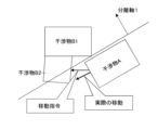
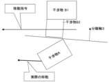
- Fig. 28F is a schematic diagram showing how the actual movement coincides with the movement command.
- Fig. 28F shows the state of the interfering object A after it has returned to the position of the movement command.
- the vector r m of each axis movement destination is generated so that interference does not occur.
- Avoidance control example 8 is similar to the configuration of avoidance control example 3 shown in Fig. 11 and Fig. 12. That is, in a machine configuration with three orthogonal axes, the X-axis, the Y-axis, and the Z-axis, the workpiece is interfering object A and the tool is interfering object B.
- interfering object A is a free-form surface workpiece linked to a work node
- interfering object B is a tool center point linked to a tool node.
- Avoidance control example 8 differs from avoidance control example 3 in that the free-form surface is given by program coordinate values. Below, the differences from the above-mentioned configuration are explained.
- Figure 29 is a functional block diagram of the CPU (control unit) provided in a numerical control device according to an embodiment of the present invention.
- the conditional inter-element relation output unit 121 includes a conditional control point destination generation unit 122.
- the conditional control point destination generation unit 122 outputs the conditions that the control points must satisfy as the inter-element relation output.
- the conditional inter-element relation output unit 121 outputs the conditions that the control points output by the conditional control point destination generation unit 122 must satisfy as conditional expressions for preventing interference by interfering objects.
- the expression that represents the interference boundary is only the program coordinate values. Therefore, interference can be easily avoided at the control point stage.
- the conditional inter-element relationship control unit 131 includes a conditional axis destination generation unit 132.
- the conditional axis destination generation unit 132 executes a process of conditionally replacing the control point destination.
- the conditional inter-element relationship control unit 131 outputs data interpolation pulses indicating the conditional destination of each axis to the interpolation unit 141.
- the interpolation unit 141 executes the above-mentioned interpolation process and transmits feedback data to the inter-element relationship output unit 114.
- FIG. 30 is a flowchart showing the avoidance control of an obstruction in an embodiment of the present invention.
- the inter-element condition setting unit 112 stores the shape of the interfering object in the machine configuration tree of the three orthogonal axes of the inter-element relationship 113.
- the inter-element condition setting unit 112 stores, for example, a free-form surface in the work node of the machine configuration tree of the inter-element relationship 113, and stores the shape of the point of the inter-element relationship 113 in the tool node.
- step S21 the conditional inter-element relationship output unit 121 outputs the inter-element relationship to the inter-element relationship control unit 115 based on the inter-element condition set in the inter-element relationship 113.
- the conditional control point destination generation unit 122 outputs the program coordinate system interference boundary based on the inter-element relationship 113 as the interference boundary.
- the program coordinate system interference boundary is an interference boundary that is composed only of elements in the program coordinate system.
- the conditional control point destination generation unit 122 then converts it into a format (inter-element relationship output) that can be interpreted by the conditional inter-element relationship control unit 131.
- the free surface stored in the inter-element relationship 113 is converted into a format that can be interpreted, for example, as shown in the following formula (52).
- the conditional inter-element relationship control unit 131 assigns a program coordinate system interference boundary flag to the inter-element relationship output, indicating that it is a program coordinate system interference boundary.
- the conditional inter-element relationship output unit 121 outputs the inter-element relationship output generated by the conditional control point destination generation unit 122.
- step S22 the conditional inter-element relationship control unit 131 uses the inter-element relationship output (program coordinate system interference boundary) whose interference boundary flag is ON as the replacement target for the control point movement destination.
- inter-element relationship output program coordinate system interference boundary
- FIG. 31 is a diagram showing an example of the coordinates of each axis destination before and after correction.
- the conditional axis destination generation unit 132 if the control point destination does not satisfy the program coordinate system interference boundary condition of formula (52), the conditional axis destination generation unit 132 generates each axis destination by replacing the elements of the control point destination based on the inter-element relationship output. As shown in FIG. 31, the conditional axis destination generation unit 132 performs a process of replacing elements of the control point destination that match the left side of the interference boundary with the right side of the interference boundary based on the inter-element relationship output, and outputs each axis destination.
- Fig. 32 is a schematic diagram showing the positional relationship between each axis destination and the tool and workpiece before and after correction. As shown in Fig. 32, an avoidance movement is added to the original control point destination vector r p in the z p direction up to the interference boundary of Formula 52, and a corrected vector r' p is generated as the destination of each axis.
- the conditional each-axis destination generator 132 generates a destination vector r m by performing normal inverse kinematics transformation on the destination generated by the conditional control point destination generator 122.
- the destination vector r m is based on formula (53) and can be expressed as formula (54).
- the vector r' p in formula (54) is the constrained control point destination (program coordinate system), and the vector r m is the destination of each axis (motor coordinate system).
- Formula (54) generates a control point destination that does not interfere with the free-form surface.
- each servo motor 50 to 54 operates based on the calculated destination of each axis to avoid the tool tip point colliding with the free-form surface.
- FIG. 33 is a functional block diagram of a CPU (control unit) included in a numerical control device according to an embodiment of the present invention.
- the inter-element relation output unit 114 may be configured to include a control point destination generation unit 123 that outputs a non-conditional destination control point instead of the conditional control point destination generation unit 122.
- the conditional control point destination generation unit 122 can separately obtain the control point conditions that the control points must satisfy, and generate conditional destinations for each axis based on the destination control point and the control point conditions.
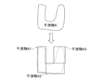
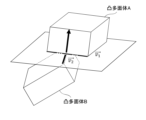
- FIG. 34 is a schematic diagram explaining the separated axis method for a polyhedron having multiple convex shapes.
- the separated axis method can be used in the method of processing the rectangular parallelepiped by dividing it into three rectangular parallelepipeds, interference object A1, interference object A2, and interference object A3.
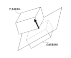
- Fig. 35A is a schematic diagram showing an example of calculation of a separation axis based on the cross product of each side of a convex polyhedron A and each side of a convex polyhedron B.
- the separation axis is calculated based on the cross product of each side of a convex polyhedron A and each side of a convex polyhedron B.
- the direction of the arrow which is the cross product of vector v1 and vector v2 becomes the separation axis.
- Fig. 35B is a schematic diagram showing an example of calculation of a separation axis based on the normal direction of each face. In Fig. 35B, the direction of the arrow which is the normal direction of each face becomes the separation axis.
- the numerical control device 100 of this embodiment includes a graph generation unit 101 that generates the mechanical configuration of the controlled object in a graph format, a control point coordinate system insertion unit 102 that inserts a control point and a coordinate system into the mechanical configuration in the graph format, an inter-element condition setting unit 112 that sets the shape of an interfering object in an inter-element relationship as an inter-element condition that must be satisfied by the relationship between a first element that is a first control point and a second element that is a second control point, an inter-element relationship output unit 114 that outputs an interference condition equation (interference boundary) for preventing interference by an interfering object based on the inter-element condition set in the inter-element relationship 113, and an inter-element relationship control unit 115 that controls the inter-element relationship based on the inter-element relationship 113 and the condition equation.
- a graph generation unit 101 that generates the mechanical configuration of the controlled object in a graph format
- a control point coordinate system insertion unit 102 that insert
- the numerical control device 100 of this embodiment is equipped with the above-mentioned configuration that utilizes a mechanical configuration in graph format, and can handle various cases of interference without having to prepare in advance avoidance commands for avoiding interference from interfering objects of different shapes.
- the element relationship output unit 114 has a conditional control point destination generator 122 that outputs a control point condition that the control point should satisfy as an element condition
- the element relationship control unit 115 has a conditional axis destination generator 132 that conditionally replaces the control point destination based on the control point condition.
- the interfering object has a complex shape, it is possible to perform an optimal movement (such as a spline-like movement) that matches the shape without unnecessary movement in the specified direction.
- an optimal movement such as a spline-like movement
- the condition of the following formula (55) is stored in the interference condition node as the interference condition, and the avoidance movement is automatically performed so that the Z-axis coordinate value z p satisfies the formula (55) that is the constraint condition.
- the inter-element relationship output unit 114 has a control point destination generation unit 123 that outputs the control point destination
- the inter-element relationship control unit 115 has a conditional axis destination generation unit 132 that generates conditional axis destinations based on the control point destination.
- the numerical control device 100 of this embodiment further includes an interpolation unit 141 that performs an interpolation process on the movement command, and the inter-element relationship control unit 115 outputs information on the movement destination of each axis reflecting the avoidance operation to the interpolation unit 141, and the avoidance operation is performed for each interpolation pulse.
- the numerical control device 100 of this embodiment further includes a command analysis unit 111 that analyzes the movement command, and the inter-element relationship control unit 115 outputs information regarding the movement destination of each axis in which the avoidance operation is reflected to the command analysis unit 111, and the avoidance operation is executed for each command block.
- the avoidance command can be incorporated into the movement command with a single correction, so an efficient movement path can be generated in cases where the avoidance operation only needs to be performed linearly.
- the interference condition equation is a condition equation that indicates an interference boundary where the interfering objects to be avoided interfere with each other. Avoidance operations can be generated accurately and efficiently using the interference boundary without the need to prepare in advance controls for performing complex avoidance operations.
- one of the interfering objects is a point
- the other is a free-form surface
- the interference condition equation is a condition equation that indicates the interference boundary between the point and the free-form surface.
- one of the interfering objects is a point that represents a motor coordinate value
- the other of the interfering objects is the movable range of the point that represents the motor coordinate value
- the interference condition equation is a condition equation that indicates the interference boundary between the point that represents the motor coordinate value and the movable range.
- the interference condition formula includes a condition that restricts movement in a specific direction. This makes it possible to fix coordinate values and restrict movement in unnecessary directions, thereby achieving a safer OT area intrusion avoidance function.
- the control method using the numerical control device 100 is realized by software.
- the programs that make up this software are installed on a computer (numerical control device 100). These programs may be recorded on removable media and distributed to users, or may be distributed by being downloaded to the user's computer via a network. Furthermore, these programs may be provided to the user's computer (numerical control device 100) as a web service via a network without being downloaded.
- a graph generating unit (101) that generates a mechanical configuration of a control target in a graph format; a control point coordinate system inserter (102) for inserting control points and a coordinate system for the machine configuration in a graph format; an inter-element condition setting unit (112) that sets the shape of an interfering object as an inter-element condition that should be satisfied by a relationship between a first element that is a first control point and a first element and a second element that is a second control point; an inter-element relationship output unit (114) that outputs an interference condition equation for preventing interference between interfering objects based on the inter-element conditions set in the inter-element relationships; and an inter-element relationship control unit (115) that controls the inter-element relationship based on the inter-element relationship and the interference condition equation.
- the element relationship output unit (114) has a control point destination generation unit (123) that outputs a control point destination
- the inter-element relation control unit (115) has a conditional axis destination generating unit (132) for generating conditional axis destinations based on the control point destinations.
- the inter-element relationship output unit has a conditional control point destination generation unit (122) that outputs a control point condition that the control point should satisfy as the inter-element condition;
- the inter-element relation control unit has a conditional each-axis destination generation unit (132) for conditionally replacing a control point destination based on the control point condition.
- An interpolation unit (141) that performs an interpolation process on the movement command
- the inter-element relationship control unit (115) outputs information regarding each axial destination reflecting the avoidance operation to the interpolation unit (141); An avoidance action is performed for each interpolation pulse.
- the interference condition equation is a condition equation that indicates an interference boundary at which objects to be avoided interfere with each other.
- the conditional axis destination generation unit generates the conditional axis destination that satisfies the interference condition equation and minimizes the square of the difference between the control point destination and the result of converting the control point destination into the axis destination by normal inverse kinematics transformation.
- one of the interfering objects is a point, and one of the interfering objects is a freeform surface;
- the interference condition formula is a condition formula that indicates the interference boundary between a point and a free-form surface.
- the interference has a shape consisting of one or more convex polyhedrons;
- the interference condition formula is a condition formula that indicates an interference boundary between convex polyhedrons.
- one of the interfering objects is a point representing a motor coordinate value
- the other of the interfering objects is a movable range of the point representing the motor coordinate value
- the interference condition equation is a condition equation that indicates an interference boundary between the point representing the motor coordinate value and the movable range.
- the interference condition formula includes a condition for restricting movement in a predetermined direction.
Landscapes
- Engineering & Computer Science (AREA)
- Human Computer Interaction (AREA)
- Manufacturing & Machinery (AREA)
- Physics & Mathematics (AREA)
- General Physics & Mathematics (AREA)
- Automation & Control Theory (AREA)
- Numerical Control (AREA)
Priority Applications (4)
| Application Number | Priority Date | Filing Date | Title |
|---|---|---|---|
| DE112023005337.5T DE112023005337T5 (de) | 2023-03-09 | 2023-03-09 | Numerische Steuerungsvorrichtung |
| CN202380095266.6A CN120712535A (zh) | 2023-03-09 | 2023-03-09 | 数值控制装置 |
| PCT/JP2023/009072 WO2024185132A1 (ja) | 2023-03-09 | 2023-03-09 | 数値制御装置 |
| JP2025505035A JPWO2024185132A1 (https=) | 2023-03-09 | 2023-03-09 |
Applications Claiming Priority (1)
| Application Number | Priority Date | Filing Date | Title |
|---|---|---|---|
| PCT/JP2023/009072 WO2024185132A1 (ja) | 2023-03-09 | 2023-03-09 | 数値制御装置 |
Publications (1)
| Publication Number | Publication Date |
|---|---|
| WO2024185132A1 true WO2024185132A1 (ja) | 2024-09-12 |
Family
ID=92674563
Family Applications (1)
| Application Number | Title | Priority Date | Filing Date |
|---|---|---|---|
| PCT/JP2023/009072 Ceased WO2024185132A1 (ja) | 2023-03-09 | 2023-03-09 | 数値制御装置 |
Country Status (4)
| Country | Link |
|---|---|
| JP (1) | JPWO2024185132A1 (https=) |
| CN (1) | CN120712535A (https=) |
| DE (1) | DE112023005337T5 (https=) |
| WO (1) | WO2024185132A1 (https=) |
Citations (3)
| Publication number | Priority date | Publication date | Assignee | Title |
|---|---|---|---|---|
| JP2014021810A (ja) * | 2012-07-20 | 2014-02-03 | Seiko Epson Corp | 衝突検出システム、衝突検出用データ生成装置、ロボットシステム、ロボット、衝突検出用データ生成方法及びプログラム |
| JP2019008479A (ja) * | 2017-06-22 | 2019-01-17 | ファナック株式会社 | 数値制御装置 |
| JP2021089467A (ja) * | 2019-12-02 | 2021-06-10 | ファナック株式会社 | 制御システム |
-
2023
- 2023-03-09 WO PCT/JP2023/009072 patent/WO2024185132A1/ja not_active Ceased
- 2023-03-09 JP JP2025505035A patent/JPWO2024185132A1/ja active Pending
- 2023-03-09 DE DE112023005337.5T patent/DE112023005337T5/de active Pending
- 2023-03-09 CN CN202380095266.6A patent/CN120712535A/zh active Pending
Patent Citations (3)
| Publication number | Priority date | Publication date | Assignee | Title |
|---|---|---|---|---|
| JP2014021810A (ja) * | 2012-07-20 | 2014-02-03 | Seiko Epson Corp | 衝突検出システム、衝突検出用データ生成装置、ロボットシステム、ロボット、衝突検出用データ生成方法及びプログラム |
| JP2019008479A (ja) * | 2017-06-22 | 2019-01-17 | ファナック株式会社 | 数値制御装置 |
| JP2021089467A (ja) * | 2019-12-02 | 2021-06-10 | ファナック株式会社 | 制御システム |
Also Published As
| Publication number | Publication date |
|---|---|
| JPWO2024185132A1 (https=) | 2024-09-12 |
| DE112023005337T5 (de) | 2025-10-23 |
| CN120712535A (zh) | 2025-09-26 |
Similar Documents
| Publication | Publication Date | Title |
|---|---|---|
| EP2098931B1 (en) | Numerical controller controlling five-axis processing machine | |
| JP4938119B2 (ja) | 工具先端点位置を制御する多軸加工機用数値制御装置 | |
| JP5009010B2 (ja) | 数値制御装置 | |
| EP1302829B1 (en) | Numerical controller | |
| CN108227631B (zh) | 数值控制装置以及数据结构 | |
| JP6549683B2 (ja) | 制御装置 | |
| US10386811B2 (en) | Numerical controller | |
| JP6644630B2 (ja) | 加工プログラム処理装置およびこれを備えた多軸加工機 | |
| JP2003195917A (ja) | 数値制御装置 | |
| US7239938B2 (en) | Interference checking for a numerical control device | |
| JPWO2011111088A1 (ja) | 数値制御装置及び数値制御装置の制御方法 | |
| JP2006309645A (ja) | 曲線補間方法 | |
| JP2010146176A (ja) | 回転軸を有する工作機械用の数値制御装置 | |
| US20100231157A1 (en) | Numerical controller having axis reconfiguration function | |
| JP2013117924A (ja) | 工具背面での切削点指令により加工を行う数値制御装置 | |
| CN112987650A (zh) | 控制系统 | |
| WO2024185132A1 (ja) | 数値制御装置 | |
| JP2006289583A (ja) | 数値制御装置 | |
| CN111650887B (zh) | 控制系统 | |
| JP7000634B1 (ja) | 制御装置 | |
| JP2007304714A (ja) | 数値制御装置 | |
| US7580770B2 (en) | Numerical controller | |
| Nagata et al. | Post processor for industrial robots—Circular arc interpolation of CLS data to generate FANUC robotic program— | |
| JP7804154B1 (ja) | 制御装置 | |
| JP7688144B2 (ja) | 制御装置及びプログラムを記録したコンピュータ読み取り可能な記録媒体 |
Legal Events
| Date | Code | Title | Description |
|---|---|---|---|
| 121 | Ep: the epo has been informed by wipo that ep was designated in this application |
Ref document number: 23926342 Country of ref document: EP Kind code of ref document: A1 |
|
| WWE | Wipo information: entry into national phase |
Ref document number: 112023005337 Country of ref document: DE |
|
| ENP | Entry into the national phase |
Ref document number: 2025505035 Country of ref document: JP Kind code of ref document: A |
|
| WWE | Wipo information: entry into national phase |
Ref document number: 2025505035 Country of ref document: JP |
|
| WWP | Wipo information: published in national office |
Ref document number: 112023005337 Country of ref document: DE |
|
| 122 | Ep: pct application non-entry in european phase |
Ref document number: 23926342 Country of ref document: EP Kind code of ref document: A1 |