WO2024185128A1 - スクロール式流体機械 - Google Patents
スクロール式流体機械 Download PDFInfo
- Publication number
- WO2024185128A1 WO2024185128A1 PCT/JP2023/009060 JP2023009060W WO2024185128A1 WO 2024185128 A1 WO2024185128 A1 WO 2024185128A1 JP 2023009060 W JP2023009060 W JP 2023009060W WO 2024185128 A1 WO2024185128 A1 WO 2024185128A1
- Authority
- WO
- WIPO (PCT)
- Prior art keywords
- scroll
- wrap
- fixed scroll
- opening
- drive shaft
- Prior art date
- Legal status (The legal status is an assumption and is not a legal conclusion. Google has not performed a legal analysis and makes no representation as to the accuracy of the status listed.)
- Ceased
Links
Images



Classifications
-
- F—MECHANICAL ENGINEERING; LIGHTING; HEATING; WEAPONS; BLASTING
- F04—POSITIVE - DISPLACEMENT MACHINES FOR LIQUIDS; PUMPS FOR LIQUIDS OR ELASTIC FLUIDS
- F04C—ROTARY-PISTON, OR OSCILLATING-PISTON, POSITIVE-DISPLACEMENT MACHINES FOR LIQUIDS; ROTARY-PISTON, OR OSCILLATING-PISTON, POSITIVE-DISPLACEMENT PUMPS
- F04C18/00—Rotary-piston pumps specially adapted for elastic fluids
- F04C18/02—Rotary-piston pumps specially adapted for elastic fluids of arcuate-engagement type, i.e. with circular translatory movement of co-operating members, each member having the same number of teeth or tooth-equivalents
- F04C18/0207—Rotary-piston pumps specially adapted for elastic fluids of arcuate-engagement type, i.e. with circular translatory movement of co-operating members, each member having the same number of teeth or tooth-equivalents both members having co-operating elements in spiral form
- F04C18/0215—Rotary-piston pumps specially adapted for elastic fluids of arcuate-engagement type, i.e. with circular translatory movement of co-operating members, each member having the same number of teeth or tooth-equivalents both members having co-operating elements in spiral form where only one member is moving
-
- F—MECHANICAL ENGINEERING; LIGHTING; HEATING; WEAPONS; BLASTING
- F04—POSITIVE - DISPLACEMENT MACHINES FOR LIQUIDS; PUMPS FOR LIQUIDS OR ELASTIC FLUIDS
- F04C—ROTARY-PISTON, OR OSCILLATING-PISTON, POSITIVE-DISPLACEMENT MACHINES FOR LIQUIDS; ROTARY-PISTON, OR OSCILLATING-PISTON, POSITIVE-DISPLACEMENT PUMPS
- F04C18/00—Rotary-piston pumps specially adapted for elastic fluids
- F04C18/02—Rotary-piston pumps specially adapted for elastic fluids of arcuate-engagement type, i.e. with circular translatory movement of co-operating members, each member having the same number of teeth or tooth-equivalents
- F04C18/0207—Rotary-piston pumps specially adapted for elastic fluids of arcuate-engagement type, i.e. with circular translatory movement of co-operating members, each member having the same number of teeth or tooth-equivalents both members having co-operating elements in spiral form
- F04C18/0246—Details concerning the involute wraps or their base, e.g. geometry
- F04C18/0253—Details concerning the base
- F04C18/0261—Details of the ports, e.g. location, number, geometry
-
- F—MECHANICAL ENGINEERING; LIGHTING; HEATING; WEAPONS; BLASTING
- F04—POSITIVE - DISPLACEMENT MACHINES FOR LIQUIDS; PUMPS FOR LIQUIDS OR ELASTIC FLUIDS
- F04C—ROTARY-PISTON, OR OSCILLATING-PISTON, POSITIVE-DISPLACEMENT MACHINES FOR LIQUIDS; ROTARY-PISTON, OR OSCILLATING-PISTON, POSITIVE-DISPLACEMENT PUMPS
- F04C29/00—Component parts, details or accessories of pumps or pumping installations, not provided for in groups F04C18/00 - F04C28/00
- F04C29/12—Arrangements for admission or discharge of the working fluid, e.g. constructional features of the inlet or outlet
Definitions
- the present invention relates to a scroll-type fluid machine.
- Patent Document 1 discloses a scroll compressor, which is one type of scroll-type fluid machine.
- This scroll compressor includes a fixed scroll, an orbiting scroll, and a drive shaft that orbits the orbiting scroll relative to the fixed scroll.
- the fixed scroll has a mirror plate, a spiral wrap standing on one surface of the mirror plate, and suction holes and discharge holes drilled in the mirror plate.
- the orbiting scroll has a mirror plate, and a spiral wrap standing on one surface of the mirror plate so as to face the fixed scroll.
- the suction hole of the fixed scroll is located in the range of the winding direction of the wrap of the orbiting scroll that is on the outermost side of the wrap of the fixed scroll between the first confinement start position (more specifically, the position where the winding end of the wrap of the orbiting scroll contacts the wrap of the fixed scroll) and the second confinement start position (more specifically, the position where the winding end of the wrap of the fixed scroll contacts the wrap of the orbiting scroll).
- first working chambers are formed between the inner periphery of the wrap of the orbiting scroll and the outer periphery of the wrap of the fixed scroll, and a first suction passage is formed on the outermost periphery of the wrap of the orbiting scroll.
- the first working chambers move in the winding direction of the wrap and sequentially perform the suction process, compression process, and discharge process.
- the first working chamber draws in gas through the suction hole of the fixed scroll and the first suction passage.
- the first working chamber compresses the gas.
- the first working chamber discharges the compressed gas through the discharge hole of the fixed scroll.
- Second working chambers are formed between the inner periphery of the wrap of the fixed scroll and the outer periphery of the wrap of the orbiting scroll, and a second suction passage is formed on the outermost periphery of the wrap of the orbiting scroll.
- the second working chambers move in the winding direction of the wrap and sequentially perform the suction process, compression process, and discharge process.
- the second working chamber draws in gas through the suction hole of the fixed scroll and the second suction passage.
- the second working chamber compresses the gas.
- the second working chamber discharges the compressed gas through the discharge hole of the fixed scroll.
- Patent Document 1 a groove is formed in the non-sliding area of the end plate of the fixed scroll to expand the cross-sectional area of the first suction passage. This reduces suction loss.
- Patent Document 1 a groove is formed in the non-sliding area of the end plate of the fixed scroll to increase the cross-sectional area of the first suction passage, thereby reducing suction loss, but there is a limit to how much reduction can be achieved.
- the present invention was made in consideration of the above, and one of its objectives is to reduce suction losses.
- the present invention includes a number of means for solving the above problems.
- a scroll-type fluid machine includes a fixed scroll having a mirror plate, a spiral wrap standing on one side of the mirror plate, and an inlet hole drilled in the mirror plate, a rotating scroll having a spiral wrap standing on one side of the mirror plate so as to face the mirror plate and the fixed scroll, and a drive shaft for rotating the rotating scroll relative to the fixed scroll.
- the inlet hole of the fixed scroll is disposed in a range of the winding direction of the wrap of the rotating scroll that is on the outermost side of the wrap of the fixed scroll between a first confinement start position where the winding end of the wrap of the rotating scroll contacts the wrap of the fixed scroll and a second confinement start position where the winding end of the wrap of the fixed scroll contacts the wrap of the rotating scroll, and is intermittently directly connected to a working chamber formed between the inner side of the wrap of the rotating scroll and the outer side of the wrap of the fixed scroll.
- the present invention makes it possible to reduce suction losses.
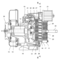
- FIG. 1 is a side view showing a structure of a scroll compressor in an embodiment to which the present invention is applied.
- 1 is an axial cross-sectional view showing a structure of a scroll compressor in one embodiment to which the present invention is applied.
- 3 is a radial cross-sectional view taken along the line III-III in FIG. 2, showing the case where the crank angle of the drive shaft is 0 degrees.
- FIG. 3 is a radial cross-sectional view taken along the line III-III of FIG. 2, showing the case where the crank angle of the drive shaft is 90 degrees.
- FIG. 3 is a radial cross-sectional view taken along the line III-III of FIG. 2, showing the case where the crank angle of the drive shaft is 180 degrees.
- FIG. 3 is a radial cross-sectional view taken along the line III-III in FIG. 2, showing the case where the crank angle of the drive shaft is 270 degrees.
- FIG. 3B is a partially enlarged cross-sectional view of portion IV of FIG. 3D.
- FIG. 5 corresponds to FIG. 4 and is a diagram for explaining the positional relationship between the suction hole of the fixed scroll and the tip seal of the orbiting scroll.
- FIG. 11 is a partially enlarged cross-sectional view of a first modified example to which the present invention is applied.
- FIG. 11 is a partially enlarged cross-sectional view of a second modified example to which the present invention is applied.
- FIG. 1 is a side view showing the structure of a scroll compressor in this embodiment.
- FIG. 2 is an axial cross-sectional view showing the structure of a scroll compressor in this embodiment.
- FIGS. 3A to 3D are radial cross-sectional views taken along the line III-III in FIG. 2, showing the crank angles of the drive shaft at 0 degrees, 90 degrees, 180 degrees, and 270 degrees, respectively.
- FIG. 4 is a partially enlarged cross-sectional view of portion IV in FIG. 3D.
- FIG. 5 corresponds to FIG. 4, and is a view for explaining the relationship between the suction hole of the fixed scroll and the tip seal of the orbiting scroll.
- the scroll compressor of this embodiment includes a casing 10, a fixed scroll 11, an orbiting scroll 12, a drive shaft 13, a cooling fan 14, and a duct 15.
- the fixed scroll 11 is connected to the open side of the casing 10 (the right side in Figs. 1 and 2).
- the orbiting scroll 12 is housed within the casing 10.
- the drive shaft 13 is rotatably supported by a bearing 16 within the casing 10.
- the cooling fan 14 rotates together with the drive shaft 13 to generate cooling air. Although only a portion of the duct 15 is shown in the figure, it guides out the cooling air generated by the cooling fan 14.
- the fixed scroll 11 has a substantially circular mirror plate 17, a spiral wrap 18 standing on one surface of the mirror plate 17 (the surface on the left side in FIG. 2), an intake hole 19 drilled in the mirror plate 17 and extending in a direction perpendicular to the aforementioned surface of the mirror plate 17 (the left-right direction in FIG. 2), and a discharge hole 20 drilled in the mirror plate 17 and extending in a direction perpendicular to the aforementioned surface of the mirror plate 17.
- An intake filter 21 is connected to the intake hole 19 of the fixed scroll 11, and a discharge pipe 22 is connected to the discharge hole 20 of the fixed scroll 11.
- the fixed scroll 11 further has a number of cooling fins 23 erected on the opposite surface of the end plate 17 (the surface on the right side in FIG. 2) and a cover 24 attached to the tip side of the cooling fins 23. Cooling air from the duct 15 flows through the flow path formed by the cooling fins 23 and the cover 24. This cools the fixed scroll 11.
- the orbiting scroll 12 has a substantially circular mirror plate 25, a spiral wrap 26 erected on one surface of the mirror plate 25 (the surface on the right side in FIG. 2) so as to face the fixed scroll 11, a number of cooling fins 27 erected on the opposite surface of the mirror plate 25 (the surface on the left side in FIG. 2), and a plate 28 attached to the tip side of the cooling fins 27. Cooling air from the duct 15 flows through the flow path formed by the cooling fins 27 and the plate 28. This cools the orbiting scroll 12.
- the wrap 26 of the orbiting scroll 12 and the wrap 18 of the fixed scroll 11 are arranged symmetrically.
- a groove 29 (see FIG. 5) is formed on the tip side of the wrap 26 of the orbiting scroll 12, and a chip seal (sliding material) 30 (see FIG. 5) is inserted into the groove 29, and the chip seal 30 comes into contact with the end plate 17 of the fixed scroll 11.
- a groove is formed on the tip side of the wrap 18 of the fixed scroll 11, and a chip seal is inserted into this groove, and the chip seal comes into contact with the end plate 25 of the orbiting scroll 12. This improves the sealing of the working chamber, which will be described later.
- a crank portion 31 is provided on one end side of the drive shaft 13 (the right side in Figs. 1 and 2).
- the center O2 of the crank portion 31 of the drive shaft 13 is eccentric from the center O1 of the drive shaft 13 and is connected to the boss portion of the plate 28 of the orbiting scroll 12 via an orbiting bearing 32.
- the other end of the drive shaft 13 protrudes outside the casing 10, and is provided with a pulley 33.
- a belt (not shown) is stretched between the pulley (not shown) provided on the rotating shaft (not shown) of the electric motor and the pulley 33. This transmits the rotational force of the electric motor, causing the drive shaft 13 to rotate, and the orbiting scroll 12 to orbit relative to the fixed scroll 11.
- An anti-rotation mechanism for preventing the orbiting scroll 12 from rotating on its own axis is provided inside the casing 10.
- the crank angle of the drive shaft 13 is the rotation angle of the straight line connecting the aforementioned centers O1 and O2, and as shown in FIG. 3A, the angle at which the winding end of the wrap 26 of the orbiting scroll 12 touches the wrap 18 of the fixed scroll 11 and the winding end of the wrap 18 of the fixed scroll 11 touches the wrap 26 of the orbiting scroll 12 is taken as the reference (0 degrees).
- the suction hole 19 of the fixed scroll 11 is disposed in a range in the winding direction of the wrap 18 (in other words, a range in the circumferential direction of the drive shaft 13) in which the wrap 26 of the orbiting scroll 12 is located on the outermost side of the wrap 18 of the fixed scroll 11 between the first confinement start position A (specifically, the position where the winding end of the wrap 26 of the orbiting scroll 12 contacts the wrap 18 of the fixed scroll 11) and the second confinement start position B (specifically, the position where the winding end of the wrap 18 of the fixed scroll 11 contacts the wrap 26 of the orbiting scroll 12) shown in FIG. 3A.
- the suction hole 19 of the fixed scroll 11 is disposed in a position in the winding direction of the wrap 18 (in other words, a position in the circumferential direction of the drive shaft 13) that is intermediate between the first confinement start position A and the second confinement start position B.
- a plurality of first working chambers 34 are formed between the inner circumferential side of the wrap 26 of the orbiting scroll 12 (more specifically, the inner surface CD shown in FIG. 3B) and the outer circumferential side of the wrap 18 of the fixed scroll 11 (more specifically, the outer surface FG shown in FIG. 3B), and a first suction passage 35 is formed on the outermost circumferential side of the wrap 26 of the orbiting scroll 12.
- the first working chamber 34 moves in the winding direction of the wrap 26 and sequentially performs the suction process, compression process, and discharge process.
- the suction process is performed to suck in gas (e.g., air) through the suction filter 21, the suction hole 19 of the fixed scroll 11, and the first suction passage 35.
- gas e.g., air
- the compression process is performed to compress (pressurize) the gas.
- the discharge process is performed to discharge compressed gas through the discharge hole 20 of the fixed scroll 11 and the discharge pipe 22.
- a number of second working chambers 36 are formed between the inner circumferential side of the wrap 18 of the fixed scroll 11 (more specifically, the inner surface HG shown in FIG. 3B) and the outer circumferential side of the wrap 26 of the orbiting scroll 12 (more specifically, the outer surface ED shown in FIG. 3B), and a second suction passage 37 is formed on the outermost circumferential side of the wrap 26 of the orbiting scroll 12.
- the second working chamber 36 moves in the winding direction of the wrap 26 and sequentially performs the suction process, compression process, and discharge process.
- the crank angle of the drive shaft 13 is between 0 and 360 degrees (in other words, during one rotation of the drive shaft 13)
- the suction process is performed in which gas is sucked in through the suction filter 21, the suction hole 19 of the fixed scroll 11, and the second suction passage 37.
- the crank angle of the drive shaft 13 is between 360 and 1170 degrees (in other words, by the time the drive shaft 13 rotates three times and the crank angle of the drive shaft 13 reaches 90 degrees)
- the compression process is performed in which gas is compressed.
- the discharge process is performed in which compressed gas is discharged through the discharge hole 20 of the fixed scroll 11 and the discharge pipe 22.
- the suction hole 19 of the fixed scroll 11 is intermittently directly connected to the first working chamber 34 during the suction process.
- the suction hole 19 of the fixed scroll 11 has an opening 19a that opens to one side of the end plate 17 described above, and the opening 19a partially overlaps with the movement range of the wrap 26 of the orbiting scroll 12. In other words, the opening 19a of the suction hole 19 of the fixed scroll 11 partially overlaps with the movement range of the first working chamber 34 during the suction process.
- the opening 19a of the suction hole 19 of the fixed scroll 11 does not overlap with the first working chamber 34 during the suction process. Therefore, the suction hole 19 of the fixed scroll 11 communicates with the first working chamber 34 during the suction process from the entire opening 19a via the first suction passage 35.
- the crank angle of the drive shaft 13 is in the second range (e.g., 225 to 315 degrees)
- a part of the opening 19a of the suction hole 19 of the fixed scroll 11 overlaps with the first working chamber 34 in the suction process
- the other part does not overlap with the first working chamber 34 in the suction process. Therefore, the suction hole 19 of the fixed scroll 11 directly communicates with the first working chamber 34 in the suction process from a part of the opening 19a, and communicates with the first working chamber 34 in the suction process from the other part of the opening 19a via the first suction passage 35. This makes it possible to reduce suction loss compared to a case in which the suction hole 19 of the fixed scroll 11 does not directly communicate with the first working chamber 34 in the suction process.
- the suction hole 19 of the fixed scroll 11 does not overlap with the end of the tip seal 30 inserted into the groove 29 of the wrap 26 of the orbiting scroll 12 on the winding end side (the outer end in the winding direction), but overlaps intermittently with other parts of the tip seal 30 (see Figure 5). Therefore, unlike the case where the suction hole 19 of the fixed scroll 11 overlaps with the end of the tip seal 30, it is possible to prevent the tip seal 30 from falling off from the groove 29 of the wrap 26.
- the opening 19a of the suction hole 19 of the fixed scroll 11 is described as being trapezoidal in shape, but this is not limited thereto.
- the opening 19a of the suction hole 19 of the fixed scroll 11 may be in a comb shape that branches in the winding direction of the wrap.
- the area where the chip seal 30 inserted into the groove 29 of the wrap 26 of the orbiting scroll 12 overlaps with the opening 19a is reduced, further preventing the chip seal 30 from falling off from the groove 29 of the wrap 26.
- the suction hole 19 of the fixed scroll 11 has one opening 19a that opens into one surface of the end plate 17, but this is not limited to the above.
- the suction hole 19 of the fixed scroll 11 may have multiple openings 19b, 19c that open into one surface of the end plate 17 and are separated from each other.
- the openings 19b and 19c of the suction hole 19 of the fixed scroll 11 do not overlap with the first working chamber 34 during the suction process. Therefore, the suction hole 19 of the fixed scroll 11 communicates with the first working chamber 34 during the suction process from the openings 19b and 19c via the first suction passage 35.
- the opening 19b of the suction hole 19 of the fixed scroll 11 overlaps with the first working chamber 34 during the suction process, and the opening 19c does not overlap with the first working chamber 34 during the suction process. Therefore, the suction hole 19 of the fixed scroll 11 directly communicates with the first working chamber 34 during the suction process through the opening 19b, and also communicates with the first working chamber 34 during the suction process through the opening 19c via the first suction passage 35. This makes it possible to reduce suction loss compared to when the suction hole 19 of the fixed scroll 11 does not directly communicate with the first working chamber 34 during the suction process.
- the area where the tip seal 30 inserted into the groove 29 of the wrap 26 of the orbiting scroll 12 overlaps with the openings 19b and 19c is reduced, further preventing the tip seal 30 from falling out of the groove 29 of the wrap 26.
- the present invention has been described as being applied to a scroll compressor, which is one type of scroll fluid machine, but the present invention is not limited to this.
- the present invention may also be applied to other scroll fluid machines (specifically, scroll vacuum pumps, scroll expanders, etc.).
Landscapes
- Engineering & Computer Science (AREA)
- Mechanical Engineering (AREA)
- General Engineering & Computer Science (AREA)
- Rotary Pumps (AREA)
Priority Applications (4)
| Application Number | Priority Date | Filing Date | Title |
|---|---|---|---|
| PCT/JP2023/009060 WO2024185128A1 (ja) | 2023-03-09 | 2023-03-09 | スクロール式流体機械 |
| CN202380056142.7A CN119604683A (zh) | 2023-03-09 | 2023-03-09 | 涡旋式流体机械 |
| EP23926338.7A EP4678917A1 (en) | 2023-03-09 | 2023-03-09 | Scroll-type fluid machine |
| JP2025505032A JP7795685B2 (ja) | 2023-03-09 | 2023-03-09 | スクロール式流体機械 |
Applications Claiming Priority (1)
| Application Number | Priority Date | Filing Date | Title |
|---|---|---|---|
| PCT/JP2023/009060 WO2024185128A1 (ja) | 2023-03-09 | 2023-03-09 | スクロール式流体機械 |
Publications (1)
| Publication Number | Publication Date |
|---|---|
| WO2024185128A1 true WO2024185128A1 (ja) | 2024-09-12 |
Family
ID=92674559
Family Applications (1)
| Application Number | Title | Priority Date | Filing Date |
|---|---|---|---|
| PCT/JP2023/009060 Ceased WO2024185128A1 (ja) | 2023-03-09 | 2023-03-09 | スクロール式流体機械 |
Country Status (4)
| Country | Link |
|---|---|
| EP (1) | EP4678917A1 (https=) |
| JP (1) | JP7795685B2 (https=) |
| CN (1) | CN119604683A (https=) |
| WO (1) | WO2024185128A1 (https=) |
Citations (3)
| Publication number | Priority date | Publication date | Assignee | Title |
|---|---|---|---|---|
| JPS59102991U (ja) * | 1982-12-27 | 1984-07-11 | トキコ株式会社 | スクロ−ル式圧縮機 |
| JPH02101092U (https=) * | 1989-01-30 | 1990-08-10 | ||
| JP2008185020A (ja) | 2007-01-31 | 2008-08-14 | Hitachi Ltd | スクロール式流体機械 |
-
2023
- 2023-03-09 CN CN202380056142.7A patent/CN119604683A/zh active Pending
- 2023-03-09 JP JP2025505032A patent/JP7795685B2/ja active Active
- 2023-03-09 EP EP23926338.7A patent/EP4678917A1/en active Pending
- 2023-03-09 WO PCT/JP2023/009060 patent/WO2024185128A1/ja not_active Ceased
Patent Citations (3)
| Publication number | Priority date | Publication date | Assignee | Title |
|---|---|---|---|---|
| JPS59102991U (ja) * | 1982-12-27 | 1984-07-11 | トキコ株式会社 | スクロ−ル式圧縮機 |
| JPH02101092U (https=) * | 1989-01-30 | 1990-08-10 | ||
| JP2008185020A (ja) | 2007-01-31 | 2008-08-14 | Hitachi Ltd | スクロール式流体機械 |
Also Published As
| Publication number | Publication date |
|---|---|
| EP4678917A1 (en) | 2026-01-14 |
| CN119604683A (zh) | 2025-03-11 |
| JPWO2024185128A1 (https=) | 2024-09-12 |
| JP7795685B2 (ja) | 2026-01-07 |
Similar Documents
| Publication | Publication Date | Title |
|---|---|---|
| JP4142418B2 (ja) | スクロール式流体機械 | |
| WO2011019021A1 (ja) | スクロール型流体機械 | |
| JP5998012B2 (ja) | スクロール式流体機械 | |
| KR20140136798A (ko) | 스크롤 압축기 | |
| CN114867941B (zh) | 涡旋式流体机械 | |
| JP7795685B2 (ja) | スクロール式流体機械 | |
| JP7808234B2 (ja) | スクロール式流体機械 | |
| JP2004116471A (ja) | スクロール式流体機械 | |
| WO2016043132A1 (ja) | スクロール型流体機械 | |
| CN111156166B (zh) | 涡旋式真空泵 | |
| JPH0749027Y2 (ja) | スクロール流体機械 | |
| US20200248692A1 (en) | Scroll compressor | |
| JP2004324616A (ja) | スクロール式流体機械 | |
| JP2008185020A (ja) | スクロール式流体機械 | |
| JPS60166782A (ja) | スクロール流体機械 | |
| WO2020170886A1 (ja) | 密閉型圧縮機 | |
| JP2925654B2 (ja) | スクロール圧縮機 | |
| JP3216454B2 (ja) | スクロール型流体装置 | |
| JP5136878B2 (ja) | スクロール流体機械 | |
| JP3858578B2 (ja) | スクロール式流体機械 | |
| JP3596063B2 (ja) | スクロール圧縮機 | |
| JPH04234591A (ja) | スクロ−ル形圧縮機 | |
| JP3036927B2 (ja) | スクロール圧縮機 | |
| JP3815747B2 (ja) | オイルフリー真空ポンプ | |
| JP2919550B2 (ja) | スクロール圧縮機 |
Legal Events
| Date | Code | Title | Description |
|---|---|---|---|
| 121 | Ep: the epo has been informed by wipo that ep was designated in this application |
Ref document number: 23926338 Country of ref document: EP Kind code of ref document: A1 |
|
| WWE | Wipo information: entry into national phase |
Ref document number: 2025505032 Country of ref document: JP |
|
| WWE | Wipo information: entry into national phase |
Ref document number: 202380056142.7 Country of ref document: CN |
|
| WWP | Wipo information: published in national office |
Ref document number: 202380056142.7 Country of ref document: CN |
|
| WWE | Wipo information: entry into national phase |
Ref document number: 202517022340 Country of ref document: IN |
|
| WWP | Wipo information: published in national office |
Ref document number: 202517022340 Country of ref document: IN |
|
| WWE | Wipo information: entry into national phase |
Ref document number: 2023926338 Country of ref document: EP |
|
| NENP | Non-entry into the national phase |
Ref country code: DE |
|
| ENP | Entry into the national phase |
Ref document number: 2023926338 Country of ref document: EP Effective date: 20251009 |
|
| ENP | Entry into the national phase |
Ref document number: 2023926338 Country of ref document: EP Effective date: 20251009 |
|
| ENP | Entry into the national phase |
Ref document number: 2023926338 Country of ref document: EP Effective date: 20251009 |
|
| ENP | Entry into the national phase |
Ref document number: 2023926338 Country of ref document: EP Effective date: 20251009 |
|
| WWP | Wipo information: published in national office |
Ref document number: 2023926338 Country of ref document: EP |