WO2024176876A1 - 冷却ファン及び電子機器 - Google Patents
冷却ファン及び電子機器 Download PDFInfo
- Publication number
- WO2024176876A1 WO2024176876A1 PCT/JP2024/004578 JP2024004578W WO2024176876A1 WO 2024176876 A1 WO2024176876 A1 WO 2024176876A1 JP 2024004578 W JP2024004578 W JP 2024004578W WO 2024176876 A1 WO2024176876 A1 WO 2024176876A1
- Authority
- WO
- WIPO (PCT)
- Prior art keywords
- guide
- cooling fan
- edge
- axial direction
- outer guide
- Prior art date
- Legal status (The legal status is an assumption and is not a legal conclusion. Google has not performed a legal analysis and makes no representation as to the accuracy of the status listed.)
- Ceased
Links
Images





Classifications
-
- F—MECHANICAL ENGINEERING; LIGHTING; HEATING; WEAPONS; BLASTING
- F04—POSITIVE - DISPLACEMENT MACHINES FOR LIQUIDS; PUMPS FOR LIQUIDS OR ELASTIC FLUIDS
- F04D—NON-POSITIVE-DISPLACEMENT PUMPS
- F04D29/00—Details, component parts, or accessories
- F04D29/26—Rotors specially for elastic fluids
- F04D29/28—Rotors specially for elastic fluids for centrifugal or helico-centrifugal pumps for radial-flow or helico-centrifugal pumps
- F04D29/30—Vanes
-
- F—MECHANICAL ENGINEERING; LIGHTING; HEATING; WEAPONS; BLASTING
- F04—POSITIVE - DISPLACEMENT MACHINES FOR LIQUIDS; PUMPS FOR LIQUIDS OR ELASTIC FLUIDS
- F04D—NON-POSITIVE-DISPLACEMENT PUMPS
- F04D17/00—Radial-flow pumps, e.g. centrifugal pumps; Helico-centrifugal pumps
- F04D17/08—Centrifugal pumps
- F04D17/16—Centrifugal pumps for displacing without appreciable compression
-
- F—MECHANICAL ENGINEERING; LIGHTING; HEATING; WEAPONS; BLASTING
- F04—POSITIVE - DISPLACEMENT MACHINES FOR LIQUIDS; PUMPS FOR LIQUIDS OR ELASTIC FLUIDS
- F04D—NON-POSITIVE-DISPLACEMENT PUMPS
- F04D25/00—Pumping installations or systems
- F04D25/02—Units comprising pumps and their driving means
- F04D25/06—Units comprising pumps and their driving means the pump being electrically driven
- F04D25/0606—Units comprising pumps and their driving means the pump being electrically driven the electric motor being specially adapted for integration in the pump
- F04D25/0613—Units comprising pumps and their driving means the pump being electrically driven the electric motor being specially adapted for integration in the pump the electric motor being of the inside-out type, i.e. the rotor is arranged radially outside a central stator
-
- F—MECHANICAL ENGINEERING; LIGHTING; HEATING; WEAPONS; BLASTING
- F04—POSITIVE - DISPLACEMENT MACHINES FOR LIQUIDS; PUMPS FOR LIQUIDS OR ELASTIC FLUIDS
- F04D—NON-POSITIVE-DISPLACEMENT PUMPS
- F04D29/00—Details, component parts, or accessories
- F04D29/26—Rotors specially for elastic fluids
- F04D29/28—Rotors specially for elastic fluids for centrifugal or helico-centrifugal pumps for radial-flow or helico-centrifugal pumps
- F04D29/281—Rotors specially for elastic fluids for centrifugal or helico-centrifugal pumps for radial-flow or helico-centrifugal pumps for fans or blowers
-
- F—MECHANICAL ENGINEERING; LIGHTING; HEATING; WEAPONS; BLASTING
- F04—POSITIVE - DISPLACEMENT MACHINES FOR LIQUIDS; PUMPS FOR LIQUIDS OR ELASTIC FLUIDS
- F04D—NON-POSITIVE-DISPLACEMENT PUMPS
- F04D29/00—Details, component parts, or accessories
- F04D29/26—Rotors specially for elastic fluids
- F04D29/28—Rotors specially for elastic fluids for centrifugal or helico-centrifugal pumps for radial-flow or helico-centrifugal pumps
- F04D29/281—Rotors specially for elastic fluids for centrifugal or helico-centrifugal pumps for radial-flow or helico-centrifugal pumps for fans or blowers
- F04D29/282—Rotors specially for elastic fluids for centrifugal or helico-centrifugal pumps for radial-flow or helico-centrifugal pumps for fans or blowers the leading edge of each vane being substantially parallel to the rotation axis
-
- F—MECHANICAL ENGINEERING; LIGHTING; HEATING; WEAPONS; BLASTING
- F04—POSITIVE - DISPLACEMENT MACHINES FOR LIQUIDS; PUMPS FOR LIQUIDS OR ELASTIC FLUIDS
- F04D—NON-POSITIVE-DISPLACEMENT PUMPS
- F04D29/00—Details, component parts, or accessories
- F04D29/40—Casings; Connections of working fluid
- F04D29/52—Casings; Connections of working fluid for axial pumps
- F04D29/54—Fluid-guiding means, e.g. diffusers
- F04D29/541—Specially adapted for elastic fluid pumps
- F04D29/545—Ducts
Definitions
- This disclosure relates to a cooling fan and an electronic device.
- cooling fans are arranged to cool heat-generating components such as the CPU (Central Processing Unit) and GPU (Graphics Processing Unit) mounted on a circuit board.
- the cooling fans are arranged along the edge of the circuit board.
- the circuit board is located between both ends (upper and lower ends) of the cooling fan in the axial direction (vertical direction). With this arrangement, a single cooling fan blows air to both the upper and lower sides of the circuit board.
- the cooling fan proposed in this disclosure has an impeller including a plurality of fins arranged in the direction of rotation, each fin having a first end in the axial direction and a second end opposite the first end.
- the cooling fan has an outer guide and an inner guide.
- the outer guide has a portion located between the first end and the second end in the axial direction and between two adjacent fins, and guides air toward the radial outside of the impeller.
- the inner guide is located between the first end and the second end in the axial direction, is located closer to the radial center than the outer guide, and guides air toward the radial outside of the impeller.
- the electronic device proposed in this disclosure has the cooling fan and a circuit board located between the first end and the second end in the axial direction.
- This cooling fan allows for greater freedom in adjusting the airflow by using the outer and inner guides. As a result, it becomes easier to optimize the flow rate and speed of the air sent out toward one side (e.g., the top side) and the opposite side (e.g., the bottom side) of the circuit board, improving the cooling performance of the cooling fan for heat-generating components located above and below the circuit board.
- FIG. 1 is a perspective view showing a first example of a cooling fan proposed in the present disclosure.
- FIG. 2 is a perspective view of the cooling fan shown in FIG. 1 .
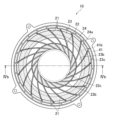
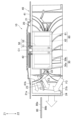
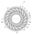
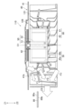
- FIG. 2 is a bottom view of the cooling fan shown in FIG. 4 is a cross-sectional view taken along line IVb-IVb shown in FIG. 3.
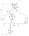
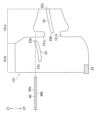
- 4B is a diagram showing the positional relationship between the outer guide, the inner guide, and the circuit board shown in FIG. 4A.
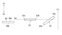
- 13A and 13B are diagrams illustrating another example of the positional relationship between the outer guide, the inner guide, and the circuit board.
- 13 is a diagram showing yet another example of the positional relationship between the outer guide, the inner guide, and the circuit board.
- FIG. 11 is a perspective view showing a second example of a cooling fan proposed in the present disclosure.
- FIG. 7 is a bottom view of the cooling fan shown in FIG. 6 .
- 8 is a cross-sectional view taken along line VIIa-VIIa shown in FIG. 7.
- 8B is a diagram showing the positional relationship between the outer guide, the inner guide, and the circuit board shown in FIG. 8A.
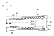
- 1A and 1B are diagrams illustrating examples of electronic devices equipped with a cooling fan.
- FIG. 10 is a front view of the electronic device shown in FIG. 9 .
- cooling fan 10 see FIG. 1
- cooling fan 110 see FIG. 6
- electronic device 90 see FIG. 9
- the Z1 and Z2 directions shown in Figure 1 etc. will be referred to as the upward and downward directions, respectively.
- the X1 and X2 directions will be referred to as the right and left directions, respectively
- the Y1 and Y2 directions will be referred to as the front and rear directions, respectively.
- These directions are defined to explain the shapes and relative positional relationships of the elements (components, members, and parts) of cooling fan 10 and electronic device 90. Therefore, the directions shown in the figures do not limit the attitude of cooling fan 10/110 and electronic device 90 during use.
- the cooling fan 10 has an impeller 20.
- the impeller 20 is rotatable about an axis C1 that is aligned in the up-down direction.
- the impeller 20 has a plurality of fins 21 that are aligned in the rotational direction.
- the cooling fan 10 has an electric motor 60 at its center.
- the electric motor 60 has a stator 62 and a rotor 61 surrounding the stator 62.
- the cooling fan 10 also has a motor housing 30 that houses the electric motor 60.
- the motor housing 30 has a cylindrical portion 30a and a bottom portion 30b located at the lower end of the cylindrical portion 30a.
- the rotor 61 of the electric motor 60 is fixed to the cylindrical portion 30a.
- the impeller 20 is fixed to the motor housing 30, and rotates when driven by the electric motor 60.
- the impeller 20 and the motor housing 30 may be molded integrally from resin.
- the fins 21 are plate-shaped formed along the axial direction and extend radially outward from the impeller 20.
- the fins 21 may extend, for example, in a direction oblique to both the radial direction and the rotational direction of the impeller 20.
- the fins 21 may also be curved along a part of a clothoid curve. This shape of the fins 21 can increase the efficiency of air introduction and discharge by the cooling fan 10.
- the ends of the fins 21 (ends closer to the center in the radial direction) may be fixed to the cylindrical portion 30a of the motor housing 30. Alternatively, the ends of the fins 21 (ends closer to the center in the radial direction) may be connected to the outer edge 22b of the annular inner guide 22 described later.
- the cooling fan 10 has a base plate 40.
- the base plate 40 has an annular outer base portion 41 and a central base portion 42 formed inside the outer base portion 41 and intersecting with the axis C1 of the cooling fan 10.
- the outer base portion 41 has a number of mounting portions 41a that protrude radially outward. When the impeller 20 rotates, air is introduced into the impeller 20 through openings between the central base portion 42 and the outer base portion 41.
- the base plate 40 is disposed, for example, on one side in the axial direction of the impeller 20 (the upper side in the illustrated example).
- the cooling fan 10 has a support portion 50 for supporting the electric motor 60.
- the support portion 50 has a motor support portion 52 that is located inside the motor housing 30 and supports the stator 62.
- the support portion 50 has a fixing portion 51 at its upper end that is fixed to the central base portion 42.
- the fixing portion 51 and the motor support portion 52 may be connected to each other, for example, through a through hole formed in the central base portion 42.
- the fixing portion 51 and the motor support portion 52 may be integrally molded from resin.
- the central base portion 42 of the base plate 40 is located above the outer periphery base portion 41. This allows the electric motor 60 and the motor housing 30 that houses it to be shifted upward. As a result, the amount of air introduced into the impeller 20 from below the cooling fan 10 can be increased.
- the base plate 40 When the cooling fan 10 is mounted on the electronic device 90, the base plate 40 may be positioned above the impeller 20, or conversely, the base plate 40 may be positioned below the impeller 20.
- the electronic device 90 has a circuit board 80 (see FIG. 10). As shown in FIG. 4A, the cooling fan 10 is arranged along the edge of the circuit board 80 when mounted on the electronic device 90.
- the position of the circuit board 80 in the axial direction of the cooling fan 10 (in the example shown in the figure, the vertical direction (Z1-Z2 direction)) is between the upper end 21a and the lower end 21b of the fins 21.
- the impeller 20 rotates, part of the airflow flows along the upper surface 80a of the circuit board 80, and another part of the airflow flows along the lower surface 80b of the circuit board 80. This allows both the components (subjects to be cooled) arranged above the circuit board 80 and the components (subjects to be cooled) arranged below the circuit board 80 to be cooled by a single cooling fan 10.
- components that generate more heat are mounted on the underside 80b of the circuit board 80 than the components on the upper side of the circuit board 80.
- the impeller 20 and the circuit board 80 are arranged and configured to supply more air to the underside 80b of the circuit board 80 than to the upper side 80a of the circuit board 80.
- Components that generate a large amount of heat such as integrated circuits such as a CPU, GPU, or memory, or a SoC (System on a chip) having these functions, may be provided on the underside 80b of the circuit board 80.
- the impeller 20 has an outer guide 23.
- the outer guide 23 is located between the upper end 21a and the lower end 21b of the fin 21 in the axial direction (Z1-Z2) of the cooling fan 10. That is, the outer guide 23 is located downwardly away from the upper end 21a and upwardly away from the lower end 21b.
- the outer guide 23 may be disposed, for example, offset in the axial direction with respect to a horizontal plane H4 (see Fig. 4B, a plane perpendicular to the axial direction) that passes through the middle between the upper end 21a and the lower end 21b of the fin 21.
- the outer guide 23 has a portion located between two adjacent fins 21. As shown in FIG. 3, the outer guide 23 is, for example, annular and surrounds the entire circumference of the motor housing 30, connecting all of the fins 21. (The outer guide 23 is also shaded in FIG. 3.) Therefore, a portion of the outer guide 23 is formed between any two adjacent fins 21.
- the impeller 20 has an inner guide 22.
- the inner guide 22 is located between the upper end 21a and the lower end 21b of the fin 21 in the axial direction (Z1-Z2). In other words, the inner guide 22 is located downwardly away from the upper end 21a and upwardly away from the lower end 21b.
- the inner guide 22 is also located closer to the center (axis C1) in the radial direction than the outer guide 23.
- the inner guide 22 may have a portion located between two adjacent fins 21. As shown in FIG. 3, the inner guide 22 is, for example, an annular shape that surrounds the entire circumference of the motor housing 30 and connects all of the fins 21. (The inner guide 22 is shaded in FIG. 3.) Therefore, a portion of the inner guide 22 may be formed between any two adjacent fins 21.
- the inner edge 22c (end closer to the axis C1) of the inner guide 22 may be connected to the outer circumferential surface of the motor housing 30. Note that the end of the fin 21 closer to the axis C1 does not have to be connected to the outer circumferential surface of the motor housing 30. In this case, the inner edge 22c of the inner guide 22 may be connected to the outer circumferential surface of the motor housing 30, and the end of the fin 21 closer to the axis C1 may be connected only to the inner guide 22.
- the fin 21 has an inner region 21e whose axial width gradually increases radially outward.
- the inner guide 22 is located between the upper and lower edges of the inner region 21e.
- the inner guide 22 may be positioned, for example, so as to intersect with a horizontal plane H4 (a plane perpendicular to the axial direction) that passes through the middle between the upper end 21a and the lower end 21b of the fin 21.
- the guides 22 and 23 may be plate-shaped. That is, the widths W2 and W3 of the guides 22 and 23 may be greater than their thicknesses T2 and T3.
- the inner guide 22 and the outer guide 23 guide the air that flows into the impeller 20 from above and below radially outward.
- an air flow F1 (see FIG. 4A) is guided by the upper surface 23a (see FIG. 4B) of the outer guide 23 and sent out radially outward
- an air flow F2 (see FIG. 4A) is formed between the outer guide 23 and the inner guide 22
- an air flow F3 (see FIG. 4A) is guided by the lower surface of the outer guide 23 and the lower surface 22a (see FIG. 4B) of the inner guide 22 and sent out radially outward.
- the impeller 20 has two guides 22 and 23, which increases the degree of freedom in adjusting the airflow. As a result, it becomes easier to optimize the airflow formed along the upper surface 80a of the circuit board 80 and the airflow formed along the lower surface 80b.
- the outer edge 22b of the inner guide 22 is located inside (closer to the axis C1) than the inner edge 23b of the outer guide 23. Therefore, when the cooling fan 10 is viewed in the axial direction, the inner guide 22 and the outer guide 23 do not overlap. This can smooth the air flow passing between the inner guide 22 and the outer guide 23. It also makes it easier to mold the impeller 20 from resin.
- the position (axial position) of the inner edge 23b of the outer guide 23 is different from the position (axial position) of the inner edge 22c of the inner guide 22. This allows for more freedom in the width of the air flow path formed between the two guides 22, 23. For example, the width of the air flow path formed between the two guides 22, 23 can be increased or decreased.
- the inner edge 23b of the outer guide 23 is located above the inner edge 22c of the inner guide 22. This allows for the width of the air flow path formed between the two guides 22, 23 to be increased.
- the outer edge 22b and the inner edge 22c of the inner guide 22 may be offset to one side in the axial direction relative to the outer edge 23c and the inner edge 23b of the outer guide 23. That is, the entire inner guide 22 may be located to one side in the axial direction (lower in the example of FIG. 4B) of the horizontal plane H1 (see FIG. 4B), and the entire outer guide 23 may be located on the opposite side to the inner guide 22 with respect to the horizontal plane H1 (upper in the example of FIG. 4B). This can further increase the width of the air flow path between the inner guide 22 and the outer guide 23, and increase the amount of air passing between the two guides 22 and 23 and being sent to the lower side of the circuit board 80.
- the inner guide 22 may be inclined so that the height (position in the axial direction) of its outer edge 22b is different from the height of its inner edge 22c. This allows the direction of the airflow sent out from the impeller 20 to be adjusted by the inner guide 22.
- the inner guide 22 is inclined so that the height of the outer edge 22b is lower than the inner edge 22c. This allows air to be sent out toward the lower side of the circuit board 80.
- the outer guide 23 may also be inclined so that the height (position in the axial direction) of its outer edge 23c is different from the height of its inner edge 23b. This allows the direction of the airflow sent out from the impeller 20 to be adjusted by the outer guide 23.
- the outer guide 23 is inclined so that the height of the outer edge 23c is lower than the inner edge 23b.
- the two guides 22, 23 are inclined in the same direction.
- This shape of the guides 22, 23 can facilitate the air flow passing between the two guides 22, 23.
- the height of the outer edges 22b, 23c is lower than the inner edges 22c, 23b in both the inner guide 22 and the outer guide 23. This can facilitate the air flow passing between the two guides 22, 23 toward the underside of the circuit board 80.
- the outer guide 23 may be curved so as to bulge downward.
- the outer guide 23 may be curved along an imaginary arc formed around a center located above the outer guide 23. This curvature can increase the amount of air that flows between the two guides 22 and 23 from the upper side of the impeller 20. Note that, unlike FIG. 4B, the outer guide 23 does not have to have such a curvature.
- the inner guide 22 may be curved so as to bulge upward. That is, the inner guide 22 may be curved along an imaginary arc formed around a center located below the inner guide 22. This curvature can increase the amount of air that flows into between the two guides 22 and 23 from the upper side of the impeller 20. Note that, unlike FIG. 4B, the inner guide 22 does not have to have such a curvature.
- the circuit board 80 may be disposed above a horizontal plane H4 passing through, for example, a midpoint between the upper end 21a and the lower end 21b of the fin 21.
- the inner guide 22 may be located below the circuit board 80. More specifically, both the inner edge 22c and the outer edge 22b of the inner guide 22 may be located below the circuit board 80.
- the outer guide 23 is located above the inner guide 22.
- the outer guide 23 can increase the air flow along the upper surface 80a of the circuit board 80.
- air introduced into the impeller 20 from above hits the upper surface 23a of the outer guide 23.
- a part of the air is guided to the upper side of the upper surface 80a of the circuit board 80.
- the outer guide 23 may be located slightly below the circuit board 80. More specifically, the inner edge 23b of the outer guide 23 may be located at substantially the same height as the circuit board 80, and the outer edge 23c of the outer guide 23 may be located below the circuit board 80.
- the horizontal plane H5 plane perpendicular to the axial direction passing through the circuit board 80 passes through the inner edge 23b of the outer guide 23.
- the inventors' research has revealed that the speed of the airflow discharged from the impeller 20 varies depending on the height (position in the axial direction), and is faster at the height of the guides 22 and 23.
- the inner guide 22 is located below the circuit board 80, which contributes to improving the flow rate and speed of the airflow along the lower surface 80b of the circuit board 80.
- the outer guide 23 is positioned above the inner guide 22, while the inner edge 23b of the outer guide 23 is positioned at substantially the same height as the circuit board 80.
- This arrangement of the outer guide 23 contributes to improving the flow rate and velocity of the airflow along the upper surface 80a of the circuit board 80.
- the outer edge 23c of the outer guide 23 is located slightly below the circuit board 80. This arrangement of the outer guide 23, together with the inner guide 22, contributes to improving the flow rate of air along the lower surface 80b of the circuit board 80.
- both the outer edge 22b of the inner guide 22 and the outer edge 23c of the outer guide 23 are located below the horizontal plane H5 that includes the circuit board 80. This allows air passing between the inner guide 22 and the outer guide 23 to be supplied to the underside of the circuit board 80. Also, as shown in FIG. 4, the inner edge 23b of the outer guide 23 may be located at substantially the same position as the plane that includes the circuit board 80.
- the outer edge 23c of the outer guide 23 is located radially inward from the outer end 21c of the fin 21. This arrangement of the outer guide 23 ensures an air flow path between the circuit board 80 and the outer edge 23c of the outer guide 23, from the upper side of the outer guide 23 to the lower side of the circuit board 80.
- the positional relationship between the guides 22 and 23 and the circuit board 80 is not limited to the example shown in FIG. 4B etc.
- the outer guide 23 may be partially located above the circuit board 80.
- the inner edge 23b of the outer guide 23 may be located above the circuit board 80, while the outer edge 23c may be located below the circuit board 80.
- the outer guide 23 may be located entirely above the circuit board 80. In other words, both the inner edge 23b and the outer edge 23c of the outer guide 23 may be located above the circuit board 80.
- the inner edge 22c of the inner guide 22 may be located above the inner edge 23b of the outer guide 23, but the outer edge 22b of the inner guide 22 may be located below the inner edge 23b of the outer guide 23.
- the guides 22 and 23 do not have to be inclined.
- the outer guide 23 is formed parallel to a horizontal plane H2 that is perpendicular to the axial direction.
- the height (position in the axial direction) of the inner edge 22c of the inner guide 22 and the height of the inner edge 23b of the outer guide 23 may be the same.
- a horizontal plane H3 perpendicular to the axial direction may pass through both the inner edge 22c of the inner guide 22 and the inner edge 23b of the outer guide 23.
- the outer edge 23c of the outer guide 23 may be located higher than the outer edge 22b of the inner guide 22.
- the fin 21 has an inner region portion 21e and an outer region portion 21f.
- the inner region portion 21e is a portion where the width of the fin 21 in the axial direction gradually increases toward the outside in the radial direction.
- the outer region portion 21f is a portion where the width of the fin 21 in the axial direction is substantially constant in the radial direction.
- the outer peripheral base portion 41 (see FIG. 4A) of the base plate 40 is located above the outer region portion 21f.
- the inner region portion 21e is located inside the outer peripheral base portion 41 of the base plate 40.
- the position of the inner edge 41b (see FIG. 4A) of the outer peripheral base portion 41 in the radial direction may substantially correspond to the position of the boundary between the outer region portion 21f and the inner region portion 21e.
- the outer guide 23 may be partially positioned inside the inner edge 41b of the outer periphery base portion 41 of the base plate 40. Specifically, as shown in Figures 3 and 4A, the inner edge 23b (see Figure 3) of the outer guide 23 may be positioned inside the inner edge 41b (see Figure 3) of the outer periphery base portion 41. With this arrangement of the outer guide 23, air that passes through the opening in the base plate 40 from above the cooling fan 10 and is introduced into the impeller 20 can be more effectively guided radially outward by the outer guide 23.
- the base plate 40, outer guide 23, and inner guide 22 are aligned in the axial direction in this order.
- the outer guide 23 is positioned below the base plate 40
- the inner guide 22 is positioned below the outer guide 23.
- the outer edge 23c (see FIG. 3) of the outer guide 23 is located radially outward of the inner edge 41b of the outer periphery base portion 41. Therefore, as shown in FIG. 3, when the cooling fan 10 is viewed in the axial direction, the outer portion of the outer guide 23 overlaps with the outer periphery base portion 41 of the base plate 40. Research by the present inventors has revealed that this arrangement of the outer guide 23 can reduce noise caused by driving the cooling fan 10.
- a part of the outer guide 23 (the part close to the axis C1) is connected to the inner area portion 21e of the fin 21, and another part of the outer guide 23 (the part farther from the axis C1) is connected to the outer area portion 21f.
- the inner guide 22 is formed in the inner area portion 21e.
- the impeller 20 has a reinforcing ring 24.
- the reinforcing ring 24 connects the ends of the multiple fins 21. This reinforces the impeller 20. For example, it is possible to prevent the fins 21 from bending when the impeller 20 rotates.
- the reinforcing ring 24 is fixed to the lower end 21b of the fin 21.
- the reinforcing ring 24 may be fixed to the radial end 21c of the fin 21.
- the outer guide 23 is located inside the reinforcing ring 24. More specifically, the outer edge 23c of the outer guide 23 is located inside the inner edge 24a of the reinforcing ring 24. Therefore, when the cooling fan 10 is viewed in the axial direction, the outer guide 23 and the reinforcing ring 24 do not overlap. This makes it easier to mold the impeller 20 from resin.
- Cooling fan 110 another example of a cooling fan proposed in the present disclosure, will be described with reference to Figures 6 to 8B.
- the following description of cooling fan 110 will focus on differences between cooling fan 110 and the above-described cooling fan 10. Items not described for cooling fan 110 may be the same as those for cooling fan 10.
- the impeller 120 has multiple fins 121 arranged in the direction of rotation.
- Each fin 121 has an inner region portion 121a and an outer region portion 121b, as shown in FIG. 8B.
- the inner region portion 121a is a portion where the width of the fin 121 in the axial direction gradually increases radially outward.
- the outer region portion 121b is a portion where the width of the fin 121 in the axial direction is substantially constant radially.
- the outer peripheral base portion 41 of the base plate 40 (see FIG. 8A) is located above the outer region portion 21f.
- the inner region portion 21e is located inward from the outer peripheral base portion 41 of the base plate 40.
- recesses 121c and 121d are formed on the edge of inner area portion 121a.
- Recess 121c is formed on the upper edge of inner area portion 121a.
- Recess 121d is formed on the lower edge of inner area portion 121a.
- the impeller 120 has an inner guide 22 and an outer guide 23, similar to the impeller 20 described above.
- the inner guide 22 is connected to the inner area portion 121a.
- the inner area portion 121a has a portion located above the inner guide 22 and a portion located below the inner guide 22.
- a portion of the outer guide 23 is located in the inner area portion 121a, and the other portion is located in the outer area portion 121b.
- the electronic device 90 is, for example, an entertainment device that functions as a game device or audio-visual device.
- the electronic device 90 outputs moving image data generated by executing a game program, video and audio data acquired through a network, and video and audio data acquired from a recording medium such as an optical disk to a display device such as a television.
- the electronic device may be a personal computer or a server computer.
- the electronic device 90 has a device body 91.
- the device body 91 has a housing 91a.
- the housing 91a houses the cooling fan 10 described above.
- the cooling fan 10 is arranged so that the axis C1 passing through its center of rotation faces the vertical direction (Z1-Z2 direction) of the electronic device 90.
- the housing 91a also houses a circuit board on which various electronic components such as a CPU (Central Processing Unit) and a GPU (Graphical Processing Unit) are mounted.
- the housing 91a has a heat sink (such as a heat pipe).
- the heat sink is connected to the electronic components such as the CPU.
- the cooling fan 10 introduces external air into the housing 91a and forms an airflow that passes through the heat sink.
- the electronic device 90 has an upper exterior panel 92 that covers the upper surface of the housing 91a.
- the electronic device 90 also has a lower exterior panel 93 that covers the lower surface of the housing 91a.
- the exterior components of the electronic device 90 i.e., the upper exterior panel 92, the lower exterior panel 93, and the housing 91a
- the cooling fan 10 is disposed on the edge of the circuit board 80.
- the air introduced into the cooling fan 10 is blown outward in the radial direction by the rotation of the impeller 20, forming air flows above and below the circuit board 80.
- the cooling fan proposed in this disclosure has an impeller including a plurality of fins arranged in a rotational direction, each fin having a first end and a second end opposite to the first end in an axial direction.
- the cooling fan also has an outer guide and an inner guide.
- the outer guide has a portion located between the first end and the second end in the axial direction and between two adjacent fins, and guides air toward the radial outside of the impeller.
- the inner guide is located between the first end and the second end in the axial direction, and is located closer to the center in the radial direction than the outer guide, and guides air toward the radial outside of the impeller. Since this cooling fan has two guides, the degree of freedom in adjusting the air flow can be increased.
- the position of the outer edge and the position of the inner edge of the inner guide may be different in the axial direction. This makes it easier to adjust the direction of the air flow.
- the position of the outer edge and the position of the inner edge of the outer guide may be different in the axial direction. This makes it easier to adjust the direction of the airflow.
- the position of the outer edge of the inner guide may be located to one side in the axial direction (lower in the example shown in FIG. 4B, etc.) than the position of the inner edge of the inner guide.
- the position of the outer edge of the outer guide may be located to said one side in the axial direction (lower in the example shown in FIG. 4B, etc.) than the position of the inner edge of the outer guide. This can smooth the air flow passing between these two guides.
- the cooling fan may have a base plate located axially relative to the impeller.
- the base plate may have an annular outer peripheral base portion, and the outer guide may have a portion located radially closer to the center than the inner edge of the outer peripheral base portion. In this way, the outer guide can effectively guide the air passing inside the outer peripheral base portion.
- the outer guide may have a portion located radially outward from the inner edge of the outer periphery of the base plate. This facilitates the flow of air and reduces noise when the cooling fan is in operation.
- the base plate, the outer guide, and the inner guide may be arranged in the axial direction in this order. In this way, air introduced from the inside of the outer peripheral plate portion of the base plate can be guided by the outer guide, and air passing inside the outer guide can be guided by the inner guide.
- the inner edge of the outer guide may be positioned radially outward of the outer edge of the inner guide. This can smooth the air flow passing between the inner guide and the outer guide. It can also facilitate molding the impeller from resin.
- the cooling fan may further have a reinforcing ring portion that connects the radially outer ends of the multiple fins. This can improve the strength of the impeller.
- the outer edge of the outer guide may be positioned closer to the center in the radial direction than the inner edge of the reinforcing ring. This avoids complicating the impeller molding process.
- the position of the outer edge of the inner guide and the position of the inner edge of the outer guide may be spaced apart in the axial direction. This ensures a sufficient air flow path between the inner edge of the outer guide and the outer edge of the inner guide.
- the position of the inner edge of the outer guide and the position of the inner edge of the inner guide may be different in the axial direction. This allows for more freedom in the width of the air flow path formed between the two guides.
- the outer edge and inner edge of the inner guide may be located on one side of the outer edge and inner edge of the outer guide in the axial direction. This allows the air flow path between the outer guide and the inner guide to be further enlarged.
- the electronic device proposed in this disclosure has a cooling fan as described in (1) to (13) and a circuit board located between the first end and the second end in the axial direction.
- the position of the outer edge of the inner guide and the position of the outer edge of the outer guide may be located on one side in the axial direction from a plane including the circuit board. In this way, air passing between the inner guide and the outer guide can be supplied to one side of the circuit board.
- cooling fan proposed in the present disclosure is not limited to the above-described cooling fan 10, and may be modified in various ways.
- the electronic device proposed in the present disclosure is not limited to the above-described electronic device 90, and may be modified in various ways.
- the impeller 20 may have more than two radially aligned annular guides.
- both the outer guide 23 and the inner guide 22 are annular and connect all of the fins 21.
- the guides 22 and 23 may be provided only in a part of the rotation direction of the impeller 20. That is, the impeller 20 may have two adjacent fins 21 with no inner guide 22 and no outer guide 23 provided between them. In this way, when the guides 22 and 23 are provided only in a part of the rotation direction of the impeller 20, the outer guide 23 is located in the radial direction of the inner guide 22. That is, the position (angular position) of the outer guide 23 in the rotation direction of the impeller 20 may coincide with the position of the inner guide 22 in the rotation direction of the impeller 20.
Landscapes
- Engineering & Computer Science (AREA)
- Mechanical Engineering (AREA)
- General Engineering & Computer Science (AREA)
- Structures Of Non-Positive Displacement Pumps (AREA)
Priority Applications (3)
| Application Number | Priority Date | Filing Date | Title |
|---|---|---|---|
| JP2025502279A JPWO2024176876A1 (cg-RX-API-DMAC7.html) | 2023-02-21 | 2024-02-09 | |
| EP24760178.4A EP4671544A4 (en) | 2023-02-21 | 2024-02-09 | COOLING FAN AND ELECTRONIC DEVICE |
| CN202480012629.XA CN120641663A (zh) | 2023-02-21 | 2024-02-09 | 冷却风扇及电子设备 |
Applications Claiming Priority (2)
| Application Number | Priority Date | Filing Date | Title |
|---|---|---|---|
| JP2023025542 | 2023-02-21 | ||
| JP2023-025542 | 2023-02-21 |
Publications (1)
| Publication Number | Publication Date |
|---|---|
| WO2024176876A1 true WO2024176876A1 (ja) | 2024-08-29 |
Family
ID=92500802
Family Applications (1)
| Application Number | Title | Priority Date | Filing Date |
|---|---|---|---|
| PCT/JP2024/004578 Ceased WO2024176876A1 (ja) | 2023-02-21 | 2024-02-09 | 冷却ファン及び電子機器 |
Country Status (4)
| Country | Link |
|---|---|
| EP (1) | EP4671544A4 (cg-RX-API-DMAC7.html) |
| JP (1) | JPWO2024176876A1 (cg-RX-API-DMAC7.html) |
| CN (1) | CN120641663A (cg-RX-API-DMAC7.html) |
| WO (1) | WO2024176876A1 (cg-RX-API-DMAC7.html) |
Citations (5)
| Publication number | Priority date | Publication date | Assignee | Title |
|---|---|---|---|---|
| JPH1172099A (ja) * | 1997-08-29 | 1999-03-16 | Matsushita Electric Ind Co Ltd | 電動送風機 |
| JP2007247495A (ja) * | 2006-03-15 | 2007-09-27 | Matsushita Electric Ind Co Ltd | 遠心ファン装置及びそれを備えた電子機器 |
| JP2008157216A (ja) * | 2006-11-30 | 2008-07-10 | Matsushita Electric Ind Co Ltd | 遠心ファン装置及びそれを備えた電子機器 |
| JP2013007339A (ja) * | 2011-06-24 | 2013-01-10 | Toshiba Corp | 電動送風機 |
| WO2021193882A1 (ja) | 2020-03-27 | 2021-09-30 | 株式会社ソニー・インタラクティブエンタテインメント | 電子機器 |
Family Cites Families (7)
| Publication number | Priority date | Publication date | Assignee | Title |
|---|---|---|---|---|
| GB225640A (en) * | 1923-09-18 | 1924-12-11 | Henry Francis Joel Jr | Improvements in and relating to fans for ventilating, forced draught and like purposes |
| DE1926796U (de) * | 1961-10-12 | 1965-11-11 | Heidolph Elektro K G | Geblaese. |
| JPH1032961A (ja) * | 1996-07-16 | 1998-02-03 | Hitachi Ltd | 回転電機 |
| JP4269092B2 (ja) * | 1997-05-21 | 2009-05-27 | Toto株式会社 | 多翼遠心ファン |
| KR102257480B1 (ko) * | 2015-03-24 | 2021-05-31 | 삼성전자주식회사 | 원심팬 |
| CN114922829B (zh) * | 2018-07-12 | 2024-06-07 | 株式会社电装 | 离心式送风机 |
| JP7003902B2 (ja) * | 2018-12-14 | 2022-02-04 | 株式会社デンソー | 遠心ファン、遠心送風機 |
-
2024
- 2024-02-09 EP EP24760178.4A patent/EP4671544A4/en active Pending
- 2024-02-09 WO PCT/JP2024/004578 patent/WO2024176876A1/ja not_active Ceased
- 2024-02-09 JP JP2025502279A patent/JPWO2024176876A1/ja active Pending
- 2024-02-09 CN CN202480012629.XA patent/CN120641663A/zh active Pending
Patent Citations (5)
| Publication number | Priority date | Publication date | Assignee | Title |
|---|---|---|---|---|
| JPH1172099A (ja) * | 1997-08-29 | 1999-03-16 | Matsushita Electric Ind Co Ltd | 電動送風機 |
| JP2007247495A (ja) * | 2006-03-15 | 2007-09-27 | Matsushita Electric Ind Co Ltd | 遠心ファン装置及びそれを備えた電子機器 |
| JP2008157216A (ja) * | 2006-11-30 | 2008-07-10 | Matsushita Electric Ind Co Ltd | 遠心ファン装置及びそれを備えた電子機器 |
| JP2013007339A (ja) * | 2011-06-24 | 2013-01-10 | Toshiba Corp | 電動送風機 |
| WO2021193882A1 (ja) | 2020-03-27 | 2021-09-30 | 株式会社ソニー・インタラクティブエンタテインメント | 電子機器 |
Non-Patent Citations (1)
| Title |
|---|
| See also references of EP4671544A1 |
Also Published As
| Publication number | Publication date |
|---|---|
| JPWO2024176876A1 (cg-RX-API-DMAC7.html) | 2024-08-29 |
| EP4671544A4 (en) | 2026-06-03 |
| EP4671544A1 (en) | 2025-12-31 |
| CN120641663A (zh) | 2025-09-12 |
Similar Documents
| Publication | Publication Date | Title |
|---|---|---|
| JP5383740B2 (ja) | 電子機器 | |
| US6132170A (en) | Miniature heat dissipating fans with minimized thickness | |
| CN1318936C (zh) | 离心风扇 | |
| US7363961B2 (en) | Heat exchanger support structure of motor vehicle and supporting method | |
| JP2009099983A (ja) | 渦巻式放熱装置 | |
| US8147203B2 (en) | Fan | |
| CN101117963A (zh) | 轴流式风扇单元 | |
| JP5375099B2 (ja) | 直列式軸流ファン | |
| CN101363454A (zh) | 风扇设备 | |
| WO2021192362A1 (ja) | 電子機器 | |
| CN101089405B (zh) | 风扇装置 | |
| JP4631867B2 (ja) | 遠心ファン装置及びそれを備えた電子機器 | |
| US10371161B2 (en) | Impeller and centrifugal fan with same | |
| WO2021193879A1 (ja) | 電子機器 | |
| JP6086208B2 (ja) | 送風ファン | |
| JP2009156187A (ja) | 遠心ファン装置を備えた電子機器 | |
| JP5353864B2 (ja) | 送風装置 | |
| US7744341B2 (en) | Thermal module with centrifugal blower and electronic assembly incorporating the same | |
| JP5730653B2 (ja) | 電子機器 | |
| JP2007247495A (ja) | 遠心ファン装置及びそれを備えた電子機器 | |
| JP5500050B2 (ja) | 送風装置 | |
| CN108869389B (zh) | 扇叶结构及离心风扇 | |
| JP2008255865A (ja) | 遠心ファン装置及びそれを備えた電子機器 | |
| EP4671544A1 (en) | COOLING FAN AND ELECTRONIC DEVICE | |
| US10982681B2 (en) | Fan blade structure and centrifugal fan |
Legal Events
| Date | Code | Title | Description |
|---|---|---|---|
| 121 | Ep: the epo has been informed by wipo that ep was designated in this application |
Ref document number: 24760178 Country of ref document: EP Kind code of ref document: A1 |
|
| WWE | Wipo information: entry into national phase |
Ref document number: 202480012629.X Country of ref document: CN |
|
| ENP | Entry into the national phase |
Ref document number: 2025502279 Country of ref document: JP Kind code of ref document: A |
|
| WWE | Wipo information: entry into national phase |
Ref document number: 2025502279 Country of ref document: JP |
|
| WWP | Wipo information: published in national office |
Ref document number: 202480012629.X Country of ref document: CN |
|
| WWE | Wipo information: entry into national phase |
Ref document number: 2024760178 Country of ref document: EP |
|
| NENP | Non-entry into the national phase |
Ref country code: DE |
|
| ENP | Entry into the national phase |
Ref document number: 2024760178 Country of ref document: EP Effective date: 20250922 |
|
| ENP | Entry into the national phase |
Ref document number: 2024760178 Country of ref document: EP Effective date: 20250922 |
|
| WWP | Wipo information: published in national office |
Ref document number: 2024760178 Country of ref document: EP |