WO2024176443A1 - ロボット制御装置及びロボットシステム - Google Patents
ロボット制御装置及びロボットシステム Download PDFInfo
- Publication number
- WO2024176443A1 WO2024176443A1 PCT/JP2023/006767 JP2023006767W WO2024176443A1 WO 2024176443 A1 WO2024176443 A1 WO 2024176443A1 JP 2023006767 W JP2023006767 W JP 2023006767W WO 2024176443 A1 WO2024176443 A1 WO 2024176443A1
- Authority
- WO
- WIPO (PCT)
- Prior art keywords
- robot
- control device
- suction
- luggage
- negative pressure
- Prior art date
- Legal status (The legal status is an assumption and is not a legal conclusion. Google has not performed a legal analysis and makes no representation as to the accuracy of the status listed.)
- Ceased
Links
Images







Classifications
-
- B—PERFORMING OPERATIONS; TRANSPORTING
- B25—HAND TOOLS; PORTABLE POWER-DRIVEN TOOLS; MANIPULATORS
- B25J—MANIPULATORS; CHAMBERS PROVIDED WITH MANIPULATION DEVICES
- B25J15/00—Gripping heads and other end effectors
- B25J15/06—Gripping heads and other end effectors with vacuum or magnetic holding means
- B25J15/0616—Gripping heads and other end effectors with vacuum or magnetic holding means with vacuum
-
- B—PERFORMING OPERATIONS; TRANSPORTING
- B25—HAND TOOLS; PORTABLE POWER-DRIVEN TOOLS; MANIPULATORS
- B25J—MANIPULATORS; CHAMBERS PROVIDED WITH MANIPULATION DEVICES
- B25J13/00—Controls for manipulators
- B25J13/08—Controls for manipulators by means of sensing devices, e.g. viewing or touching devices
-
- B—PERFORMING OPERATIONS; TRANSPORTING
- B25—HAND TOOLS; PORTABLE POWER-DRIVEN TOOLS; MANIPULATORS
- B25J—MANIPULATORS; CHAMBERS PROVIDED WITH MANIPULATION DEVICES
- B25J9/00—Program-controlled manipulators
- B25J9/16—Program controls
- B25J9/1612—Program controls characterised by the hand, wrist, grip control
-
- G—PHYSICS
- G05—CONTROLLING; REGULATING
- G05B—CONTROL OR REGULATING SYSTEMS IN GENERAL; FUNCTIONAL ELEMENTS OF SUCH SYSTEMS; MONITORING OR TESTING ARRANGEMENTS FOR SUCH SYSTEMS OR ELEMENTS
- G05B2219/00—Program-control systems
- G05B2219/30—Nc systems
- G05B2219/39—Robotics, robotics to robotics hand
- G05B2219/39528—Measuring, gripping force sensor build into hand
-
- G—PHYSICS
- G05—CONTROLLING; REGULATING
- G05B—CONTROL OR REGULATING SYSTEMS IN GENERAL; FUNCTIONAL ELEMENTS OF SUCH SYSTEMS; MONITORING OR TESTING ARRANGEMENTS FOR SUCH SYSTEMS OR ELEMENTS
- G05B2219/00—Program-control systems
- G05B2219/30—Nc systems
- G05B2219/45—Nc applications
- G05B2219/45063—Pick and place manipulator
Definitions
- This disclosure relates to a robot control device and a robot system, and in particular to a robot control device that controls the operation of a robot that holds and transports an object, and a robot system that includes a robot control device and a robot.
- Patent Document 1 describes a transport device and a transport program that can transport luggage while stably holding it.
- the conveying device described in Patent Document 1 has a holding unit, a driving unit, a force sensor, a first acquisition unit, a determination unit, and a control unit.
- the holding unit holds a load
- the driving unit moves the holding unit
- the force sensor detects the force applied between the holding unit and the driving unit.
- the first acquisition unit acquires holding information indicating the holding state of the holding unit holding the load.
- the determination unit determines whether or not to transport the load based on the holding information indicating the holding state of the holding unit acquired by the first acquisition unit and the detection result of the force sensor.
- the control unit causes the driving unit to transport the load when the determination unit determines that the load is to be transported.
- Patent Document 2 describes a food holding device that can reliably hold food in a limited working space and improve the efficiency of food packing operations. Specifically, Patent Document 2 describes a food holding device in which food bodies are contained in bags.
- the holding device includes a plurality of pairs of holding members configured to sandwich and hold, along a predetermined direction, the tops of a plurality of food bags stacked in a predetermined direction at predetermined positions. Two pairs of holding members adjacent to each other in the predetermined direction are located at different positions in a direction perpendicular to the predetermined direction.
- a first representative aspect of the present disclosure is a robot control device that includes at least two sensors in a robot hand, each of which measures a holding force, and controls an operation of a robot that holds an object placed at a first point using the robot hand, lifts the object, and places the object at a second point, comprising: At least one processor; at least one storage device capable of storing a program executed by said at least one processor; Equipped with The at least one processor is a robot controller that, based on the program, determines at least one of a width, a depth, and a height of the object using at least two holding force values measured by the at least two sensors.
- a representative second aspect of the present disclosure is a robot system including the robot control device of the first aspect and a robot controlled by the robot control device.
- FIG. 1 is a configuration diagram showing an example of the configuration of a robot system according to an embodiment of the present invention
- 11 is a bottom view of the suction hand as viewed from the side where a plurality of suction pads are arranged.
- FIG. 11A and 11B are diagrams illustrating transport of luggage between pallets by a suction hand.
- FIG. 2 is a diagram showing a transport path of the luggage by the suction hand.
- 13A and 13B are diagrams showing a state in which the suction hand is tilted with respect to the luggage during the suction operation.
- 13A and 13B are diagrams illustrating a state in which the suction hand is misaligned with respect to the load during the suction operation.
- FIG. 10A to 10C are diagrams showing a method for preventing luggage from being separated from a suction pad. 13A to 13C are diagrams showing another method for preventing luggage from coming off the suction pad.
- 11 is a bottom view of the suction hand when the suction hand has sucked the load, as viewed from the side where the multiple suction pads are arranged.
- FIG. 10A to 10C are partial enlarged views of the area around the negative pressure sensor 1022A when baggage of different sizes is being attracted.
- 13 is a bottom view of the suction hand seen from the side where the multiple suction pads are arranged when the suction hand is suctioning an object in a state where the center of the suction hand does not coincide with the center of the object.
- FIG. 13A and 13B are diagrams illustrating the operation of loading a package at an optimal position on a pallet by a suction hand.
- 4 is a flowchart showing a control operation of the robot control device.
- FIG. 2 is a block diagram showing a configuration example of a robot control device configured by a computer.
- FIG. 1 is a diagram showing an example of the configuration of a robot system according to an embodiment of the present invention.
- the robot system 10 includes a robot 100 that transports an object, and a robot control device 200 that controls the operation of the robot 100.
- the robot 100 and the robot control device 200 are connected via a cable.
- the robot 100 comprises a robot mechanism 101 and a suction hand 102 attached to the tip of the robot mechanism 101.
- the suction hand 102 serves as a robot hand.
- the robot mechanism 101 has multiple joint shafts, each of which is provided with a motor. Each motor is controlled by an operation command from the robot control device 200. By controlling each motor, the robot mechanism 101 can move the suction hand 102 in the vertical and horizontal directions.
- the suction hand 102 includes a vacuum generator, a regulator that generates negative pressure (a pressure difference in the negative direction relative to atmospheric pressure), and multiple negative pressure sensors that measure the negative pressure.
- the negative pressure sensor is a sensor that measures the holding force.
- the suction hand 102 includes multiple suction pads (also called vacuum pads) 1021 inside of which negative pressure is created by the vacuum generator and the regulator, and the multiple suction pads 1021 suck the surface of the luggage, making it possible to transport the luggage.
- the suction hand 102 is equipped with a regulator that controls the negative pressure, but the negative pressure may vary depending on the shape of the load to be transported, the state of the load held by the suction hand 102, and the surrounding conditions. When the negative pressure varies, the force with which the suction hand 102 suctions the load 300 (hereinafter referred to as suction force) also varies.
- the negative pressure value indicates the suction force that serves as the holding force.
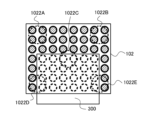
- FIG. 2 is a bottom view of the suction hand as viewed from the side where a plurality of suction pads are arranged.
- 2 includes 56 suction pads 1021 arranged in 8 columns and 7 rows, and five negative pressure sensors 1022A to 1022E that measure negative pressure.
- Negative pressure sensors 1022A, 1022B, 1022D, and 1022E each measure the negative pressure of four suction pads.
- Negative pressure sensor 1022C also measures the negative pressure of approximately four suction pads.
- an example in which there are five negative pressure sensors is shown, but the number of negative pressure sensors may be two or more, and a negative pressure sensor may be provided for each of the suction pads 1021 .
- Each of the multiple suction pads 1021 is provided with an adjustment valve.
- the adjustment valve closes when the pressure becomes high, suppressing leakage between the suction pad and the luggage, and prevents a drop in negative pressure even when there is a suction pad that does not face the luggage, making it possible to transport the luggage.
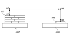
- Fig. 3 is a diagram for explaining the transportation of a load between pallets by the suction hand.
- Fig. 4 is a diagram showing the transport path of the load by the suction hand.
- positions A1, A2, B2, and B1 indicate positions where the suction pad 1021 located at the center of the suction hand 102 comes into contact with the load 300.
- Positions A1, A2, B2, and B1 are changed when the load to be transported is changed, and the transport path of the load is also changed.
- the robot control device 200 controls the transport operation of the suction hand 102 performed by the robot mechanism unit 101 and the suction and removal operations of the suction hand 102 .
- the suction hand 102 transports the unit 300 placed on the pallet 400A to the pallet 400B via a transport path for the unit 300 in the order of positions A1, A2, B2, and B1.
- the robot control device 200 causes the suction hand 102 to suck up the load 300, and between positions A1 and A2, the suction hand 102 transports (lifts) the load 300 in the vertical direction. Thereafter, the robot controller 200 causes the suction hand 102 to transport the load 300 horizontally between positions A2 and B2, and to transport (lower) the load 300 vertically between positions B2 and B1. The robot controller 200 causes the suction hand 102 to place, remove, and load the load 300 at position B1.
- the first point refers to, for example, position A1 on the pallet 400A.
- the second point refers to, for example, position B1 on the pallet 400B.
- FIGS. 3 and 4 show the first operation in which the suction hand 102 places the luggage 300 on the pallet 400B when no luggage is placed on the pallet 400B, but in the second and subsequent operations in which the suction hand 102 places the luggage 300, luggage is placed on the pallet 400B.
- the robot control device 200 performs the following operations on the transport path of the package 300 from the positions A1, A2, B2, and B1 in this order.
- the robot controller 200 measures the negative pressure value with the negative pressure sensors 1022A-1022E of the suction hand 102.
- the robot controller 200 determines that the portion where the negative pressure value is small indicates that the distance between the suction hand 102 and the load 300 is large, and changes the posture of the suction hand 102 to press the suction hand 102 against the portion where the negative pressure is weak.
- the robot controller 200 raises the suction hand 102 that has adsorbed the load 300.
- the robot control device 200 If there is a small negative pressure value among the five negative pressure values measured by the negative pressure sensors 1022A-1022E between positions A2-B2 where the load is transported horizontally, the robot control device 200 operates the robot 100 so that the small negative pressure value increases.
- the robot control device 200 grasps the width and depth of the luggage 300 by measuring the negative pressure values of the negative pressure sensors 1022A-1022E. "Width” and “depth” are sometimes called “length” and “width”, respectively. The width and depth of the luggage 300 may be grasped at position A1 or between positions A2-B2. When the luggage 300 is placed at position B1, the negative pressure value of each negative pressure sensor increases, so that the robot control device 200 grasps the height of the luggage 300.
- the robot control device 200 determines the weight of the luggage 300 based on the torque of the motor of the joint shaft, as described below.
- the robot control device 200 calculates the optimal placement position taking into account the four parameters of the width, depth, height, and weight of the luggage 300, and places the luggage 300.
- the robot controller 200 measures the negative pressure values of the negative pressure sensors 1022A to 1022E of the suction hand 102 that has adsorbed the luggage 300, and determines the difference between the negative pressure values measured by the negative pressure sensors 1022A to 1022E. Then, the robot controller 200 adjusts the attitude or position of the suction hand 102 with respect to the luggage 300 so that the difference in the negative pressure values disappears, and then adsorbs the luggage 300 to the suction hand 102.
- the robot control device 200 determines that the luggage 300 is loaded at an angle, and controls the robot mechanism unit 101 so that the difference in the negative pressure value between negative pressure sensor 1022A and negative pressure sensor 1022B, and between negative pressure sensor 1022C and negative pressure sensor 1022D disappears. As a result, the posture of the suction hand 102 is changed so that it becomes parallel to the luggage 300.
- the suction hand 102 suctions the luggage 300, if the negative pressure values (which become the holding force values) of the negative pressure sensors 1022A-1022E are each equal to or greater than a predetermined value (which becomes the holding force predetermined value), but the suction surface (which becomes the holding surface) of the luggage 300 is smaller than the predetermined value (which becomes the holding surface predetermined value), it is preferable to reset the suction hand 102, make the negative pressure values of the negative pressure sensors 1022A-1022E each equal to or greater than the predetermined value (holding force predetermined value), and make the suction surface of the luggage equal to or greater than the predetermined value (suction surface predetermined value).
- suction pads with their adjustment valves closed are indicated by circles with diagonal lines on the inside.
- the suction hand 102 is rearranged, for example, to an arrangement as shown in FIG. 9 described later, so that the negative pressure values of the negative pressure sensors 1022A to 1022E are each equal to or greater than a predetermined value (predetermined holding force value) and the suction surface of the luggage is equal to or greater than a predetermined value (predetermined suction surface value). Whether the suction surface of the luggage 300 is smaller than the predetermined holding surface value can be determined based on the negative pressure values of the negative pressure sensors 1022A to 1022E.
- the negative pressure increases as the number of suction pads closed by the adjustment valve increases. Therefore, the number of suction pads closed by the adjustment valve can be known by measuring the negative pressure value, and the size of the suction surface of the luggage 300 can be determined by evaluating the size of the surface that is not being sucked.
- the adjustment valves of the four suction pads corresponding to the negative pressure sensors 1022A and 1022B are all closed, so the negative pressure of the negative pressure sensors 1022A and 1022B is higher in the suction state in FIG. 6 than in the suction state in FIG. 9.
- the number of adjustment valves of the four suction pads corresponding to the negative pressure sensors 1022D and 1022E that are closed is one less in the suction state in FIG. 6 than in the suction state in FIG. 9, so the negative pressure of the negative pressure sensors 1022D and 1022E is lower in the suction state in FIG.
- the adjustment valves of the four suction pads corresponding to the negative pressure sensor 1022C include a closed adjustment valve, so the negative pressure of the negative pressure sensors 1022D and 1022E is higher in the suction state in FIG. 6 than in the suction state in FIG. 9.
- the number of suction pads closed by the adjustment valve can be roughly determined, and by determining the number of remaining suction pads, the size of the suction surface of the luggage 300 can be evaluated.
- the robot controller 200 measures the negative pressure values of the negative pressure sensors 1022A to 1022E of the suction hand 102 and determines the difference between the negative pressure values measured by the negative pressure sensors 1022A to 1022E. If the difference between the negative pressure values reaches or exceeds a certain value or if the difference between the negative pressure values becomes large, the robot controller 200 determines that the luggage 300 is starting to separate from the suction pad 1021 and controls the robot mechanism unit 101 so that the luggage 300 does not separate from the suction pad 1021.
- the robot control device 200 determines that the luggage 300 is beginning to separate from the suction pad 1021, and controls the robot mechanism unit 101 so that the difference in the negative pressure value between negative pressure sensor 1022A and negative pressure sensor 1022B, and between negative pressure sensor 1022C and negative pressure sensor 1022D disappears or decreases.
- the method by which the robot control device 200 controls the robot mechanism unit 101 to prevent the luggage 300 from coming off the suction pad 1021 is not particularly limited, but there are, for example, the following two methods.
- the robot mechanism 101 rotates and tilts the suction hand 102 that is suctioning the luggage 300 counterclockwise, and accelerates it in the conveying direction. This creates a force that presses the luggage 300 against the suction hand 102, preventing the luggage 300 from coming off the suction pad 1021.
- the robot mechanism 101 rotates the suction hand 102, which is adsorbing the luggage 300, by 180 degrees. Then, the luggage 300 is pressed against the suction hand 102 by gravity, and the luggage 300 can be prevented from coming off the suction pad 1021.
- the robot mechanism 101 rotates the suction hand 102, which is adsorbing the luggage 300, by 180 degrees to return it to its original position, and then moves it vertically (descending).
- the robot control device 200 performs an operation to grasp the width, depth and height of the luggage 300 according to the measurement values of the negative pressure sensors 1022A-1022E. In addition, the robot control device 200 performs an operation to grasp the weight of the luggage 300 at position B1.
- Fig. 9 is a bottom view of the suction hand when it is suctioning a load, as viewed from the side where the suction pads are arranged.
- Fig. 10A to Fig. 10C are partial enlarged views of the area around the negative pressure sensor 1022A when loads of different sizes are being suctioned.
- the 26 suction pads arranged closest to the four sides of the bottom surface of the suction hand 102 cannot adsorb the luggage 300, and the adjustment valves provided corresponding to each suction pad 1021 are closed to suppress leakage from the suction pads 1021.
- the suction pads 1021 with the adjustment valves closed are indicated by circles with diagonal lines on the inside.
- the negative pressure measured by the negative pressure sensor 1022A at this time is designated as P2. 9, when the area of the sucked load 300 is smaller than the area of the bottom surface of the suction hand 102, for example, when focusing on the negative pressure sensor 1022A, the four suction pads are closed by the adjustment valves and no leakage occurs between the suction pads and the load, as shown in Fig. 10C.
- the negative pressure measured by the negative pressure sensor 1022A at this time is P3.
- the negative pressure value P1 measured in the state of FIG. 10(A), the negative pressure value P2 measured in the state of FIG. 10(B), and the negative pressure value P3 measured in the state of FIG. 10(C) have the relationship P3>P1>P2.
- the depth D of the luggage can be estimated as the arrangement length of five suction pads 1021, and the width W of the luggage can be estimated as the arrangement length of six suction pads 1021, as shown in FIG. 9.
- the depth D of the luggage can be estimated as the arrangement length of the seven suction pads 1021, and the width W of the luggage can be estimated as the arrangement length of the eight suction pads 1021.
- the depth D of the luggage can be estimated as the arrangement length of the three suction pads 1021, and the width W of the luggage can be estimated as the arrangement length of the four suction pads 1021.
- the example shown in FIG. 9 is an example in which the center of the suction hand coincides with the center of the luggage, but as shown in FIG. 11, it is possible to estimate the depth D and width W of the luggage even if the center of the suction hand 102 does not coincide with the center of the luggage 300.
- the luggage 300 shown in FIG. 11 is smaller than the luggage 300 shown in FIG. 9.
- the negative pressure measured by the negative pressure sensors 1022A and 1022B is P1
- the negative pressure measured by the negative pressure sensors 1022D and 1022E is P3
- the negative pressure measured by the negative pressure sensor 1022A is P2
- the depth D of the luggage can be estimated as the arrangement length of the four suction pads 1021
- the width W of the luggage can be estimated as the arrangement length of the six suction pads 1021.
- the depth and width of the luggage can be estimated.
- the depth and width of the luggage can be estimated by rotating the suction hand 102 by 90 degrees.
- a negative pressure sensor may be provided for each suction pad. In this case, it is not necessary to provide a negative pressure sensor for each suction pad, and negative pressure sensors may be provided for a portion of all the suction pads.
- the depth D and width W of luggage 300 may be grasped during the vertical transport operation between positions B2 and B1, or the depth D and width W of luggage 300 may be grasped once the luggage is placed at the placement location. In the above description, both the depth D and width W of the package are grasped, but only one of them may be grasped. Also, instead of grasping both the depth D and width W of the package, only the height of the package, which will be described below, may be grasped.
- the operation of determining the height of the luggage will be described.
- the gravity of the luggage 300 is no longer applied to the suction hand 102, so the suction hand 102 and the luggage 300 come into close contact with each other and the measured negative pressure value increases.
- the height h of the tip of the suction pad of the suction hand 102 is the sum of the height h2 of the luggage to the height h1 of the pallet (or the height of the pallet plus the loaded item). Therefore, the height h2 of the luggage can be calculated by h - h1.
- the robot controller 200 controls the motor of the joint shaft to move (lower) the load 300.
- the load 300 is stopped and placed on the pallet, no force due to acceleration or deceleration is applied, and the torque of the motor depends on the weight of the load 300. Since the torque of the motor is obtained by multiplying the torque constant and the current value, the robot controller 200 can obtain the motor torque by detecting the current flowing through the motor, and can grasp the weight of the load.
- a device for calculating the torque of a motor and grasping the weight of luggage is described, for example, in JP 2020-151812 A.
- the above describes the operation of the robot control device 200 to determine the width, depth, height and weight of the luggage based on the measurement value of the negative pressure sensor between positions B2 and B1 or at position B1.
- a method of calculating an optimal placement position based on the width, depth, height and weight of the cargo and loading the transported cargo at the calculated position will be described.
- the robot control device 200 stores in the memory unit, as the loading status, the width and depth of the upper cargo of the cargo 300 stacked on the pallet 400B, and the height and weight of the cargo, together with the position (arrangement) of the cargo 300 on the cargo.
- the memory unit is, for example, the memory 221 shown in FIG. 14. 2 and 3, each time the robot control device 200 sequentially loads the cargo 300 on the pallet 400B, it calculates the width and depth of the cargo 300 on top of the load on the pallet 400 and the height and weight of the load based on the width, depth, height and weight of the transported cargo 300, and updates the loading status together with the position (arrangement) at which the cargo 300 is loaded on the load.
- the width and depth of the cargo 300 on top of the load on the pallet 400 and the position (arrangement) at which the cargo 300 is loaded on the load are information indicating the shape of the load.
- the height of the load is the height from the surface of the pallet 400B or the surface on which the pallet 400B is placed (the ground, floor, etc.) to the surface of the upper luggage 300 of the load.
- the weight of the load is the weight from the surface of the pallet 400B to the upper luggage 300 of the load, and the distribution of the weight of the load as viewed from above is stored.
- the robot control device 200 grasps the width, depth, height and weight of the luggage transported from position P1 between positions B2 and B1 or at position B1. The robot control device 200 then reads out the loading status of the luggage loaded on the pallet from the memory unit, calculates the optimal loading position (loading location) based on the loading status of the luggage and the width, depth, height and weight of the transported luggage, and loads the transported luggage in the calculated loading position.
- the robot control device 200 grasps the width, depth, height, and weight of the luggage 300A transported from position P1 between positions B2-B1 or at position B1.
- the robot control device 200 reads out the loading status of the luggage loaded on the pallet 400B from the memory unit, grasps that the space next to the luggage 300B on the pallet 400B is empty, and judges whether the luggage 300A can be placed next to the luggage 300B based on the width, depth, and height of the luggage 300A.
- the robot control device 200 also judges whether the luggage 300A can be placed next to the luggage 300B based on the weight of the luggage 300A. Then, when the robot control device 200 judges that the luggage 300A can be placed, it loads the luggage 300A next to the luggage 300B on the pallet 400B, and updates the loading status stored in the memory unit to the loading status including the loaded luggage 300A.
- the robot control device 200 grasps the width, depth, height and weight of the luggage 300C that has been transported from position P1 between positions B2 and B1 or at position B1 (the surface of luggage 300A). The robot control device 200 then reads from the memory unit the loading status of luggage 300A and luggage 300B loaded on the pallet 400B.
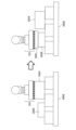
- the robot controller 200 determines whether the load 300C should be placed on top of the load 300A or on top of the load 300B based on the width, depth, height, and weight of the load 300C. Since it is desirable to load the loads on the pallet 400B with small gaps, the robot controller 200 determines the placement taking into consideration the width and depth of the load 300C. The robot controller 200 also determines the placement taking into consideration the height of the load 300C so that the variation in the height of the loaded load from the pallet 400B is small. The robot controller 200 also determines the placement taking into consideration the weight of the load 300C so that the weight of the loaded load is not unevenly distributed on the pallet 400B.
- the diagram on the right side of FIG. 12 shows an example in which the robot control device 200 places the package 300C on top of the package 300B based on the width, depth, height and weight of the package 300C.
- FIG. 13 is a flow chart showing the control operation of the robot controller 200.
- the robot controller 200 controls the suction hand 102 to transport the package 300 along a transport path in the order of positions A1, A2, B2, and B1, as shown in FIG.
- step S10 the robot control device 200 measures the negative pressure values of the negative pressure sensors 1022A-1022E of the suction hand 102, adjusts the position (posture) of the suction hand 102 with respect to the luggage 300 so that the difference in the negative pressure values is eliminated, and then adsorbs the luggage 300 to the suction hand 102.
- step S11 the robot controller 200 raises the suction hand 102 from position A1 to position A2, and horizontally moves (horizontally transports) the suction hand 102 in the horizontal transport section between positions A2 and B2 while controlling the load 300 so that it does not leave the suction hand 102.
- the operation of the robot controller 200 to control the load 300 so that it does not leave the suction hand 102 is performed, for example, as follows.
- the robot controller 200 measures the negative pressure values of the negative pressure sensors 1022A-1022E of the suction hand 102 and obtains the difference between the measured negative pressure values.
- the robot controller 200 determines that the luggage 300 is beginning to separate from the suction pad 1021 and controls the robot mechanism unit 101 so that the luggage 300 does not separate from the suction pad 1021.
- step S12 the robot control device 200 grasps the width, depth, height and weight of the package while the suction hand 102 is being transported (lowered) in the vertical direction or at the placement position.
- the width and depth of the luggage are found based on the negative pressure values of the negative pressure sensors 1022A to 1022E of the suction hand 102.
- the height of the luggage is found based on the magnitude of the change in the negative pressure values of the negative pressure sensors 1022A to 1022E of the suction hand 102.
- the weight of the luggage is found based on the torque of the motors of the joint axes of the robot, as already explained.
- step S13 the robot control device 200 reads the loading status of the luggage from the memory unit, calculates the optimal loading position based on the width, depth, height, and weight of the transported luggage determined in step S12, and loads the transported luggage in the calculated position.
- step S14 the robot control device 200 updates the loading status stored in the memory unit to include the loaded luggage.
- step S15 the robot control device 200 detaches the suction hand 102 from the baggage 300.
- step S16 the robot control device 200 judges whether the next unit is to be loaded, and if so, returns to step S10, otherwise ends the process.
- steps S10 to S16 each time a unit is loaded on the pallet, the loading status of the unit stored in the memory unit is updated.
- the cargo 300 is transported from the pallet 400A onto the pallet 400B.
- the robot control device includes a processor such as a CPU (Central Processing Unit).
- the processor functions as an execution unit.
- the robot control device may include multiple processors that operate in parallel.
- the robot control device also includes an auxiliary storage device such as an HDD (Hard Disk Drive) that stores various programs such as application software or an OS (Operating System), and a main storage device such as a RAM (Random Access Memory) for storing programs required for the processor to execute the functions of the robot control device and the operations of FIG.
- a processor such as a CPU (Central Processing Unit).
- the processor functions as an execution unit.
- the robot control device may include multiple processors that operate in parallel.
- the robot control device also includes an auxiliary storage device such as an HDD (Hard Disk Drive) that stores various programs such as application software or an OS (Operating System), and a main storage device such as a RAM (Random Access Memory) for storing programs required for the processor to execute the functions of the robot control device and the operations of FIG.
- the robot control device may include multiple main storage devices.
- the data to be stored is, for example, information on the transport route from position A1, which is the first point, to position B1, which is the second point. This information includes coordinate information of positions A1, A2, B2, and B1. Positions A1, A2, B2, and B1 are changed when the luggage to be transported is changed, and the transport route of the luggage is also changed.
- the processor reads the application software or OS from the auxiliary storage device, and while expanding the loaded application software or OS into the main storage device, performs calculations based on the application software or OS. Also, based on the results of this calculation, the various hardware components of the robot control device are controlled. In this way, the functional blocks of this embodiment are realized.
- FIG. 14 is a block diagram showing an example of the configuration of a robot control device implemented by a computer.
- the computer serving as a robot control device includes a memory 221 serving as a main storage device, a CPU 222 serving as a processor, an I/O unit 223 for connecting to the robot 100 via a cable, a disk device 224 such as an HDD serving as an auxiliary storage device, and a display unit 225.
- the display unit 225 displays the number of times the luggage has been transported, the loading status, and the like.
- the components included in the robot control device can be realized by hardware including electronic circuits, etc.
- some or all of the functions of each component included in the robot control device can be configured by integrated circuits (ICs), such as ASICs (Application Specific Integrated Circuits), gate arrays, FPGAs (Field Programmable Gate Arrays), and CPLDs (Complex Programmable Logic Devices).
- ICs integrated circuits
- ASICs Application Specific Integrated Circuits
- FPGAs Field Programmable Gate Arrays
- CPLDs Complex Programmable Logic Devices
- Non-transitory computer readable media include various types of tangible storage media. Examples of non-transitory computer readable media include magnetic recording media (e.g., hard disk drives), magneto-optical recording media (e.g., magneto-optical disks), CD-ROM (Read Only Memory), CD-R, CD-R/W, and semiconductor memory (e.g., mask ROM, PROM (Programmable ROM), EPROM (Erasable PROM), flash ROM, and RAM (random access memory)).
- the program may also be provided to the computer by various types of transitory computer readable media.
- the present embodiment described above has the following advantages.
- the robot can eliminate idle operations in a state where suction is not performed, improving transportation capacity.
- a suction hand is used as a robot hand to transport luggage.
- the robot hand is not limited to a suction hand, and the robot hand may be a gripping hand used in a prize acquisition game device in which prizes are grabbed and acquired, or a gripping hand that grabs an object using negative pressure, vacuum, or pressure.
- the robot hand may be a magnetic hand that uses magnetic force to perform suction.
- a gripping hand used in a prize acquisition game device in which a prize is grabbed and won, and a gripping hand that grabs an object using negative pressure, vacuum, or pressure can use a pressure sensor to measure how open the gripping part is when gripping an object, so that the width and depth of the object can be measured.
- a method for measuring the width and depth of an object with a gripping hand will be described later with reference to a specific example.
- the weight of the object can be calculated by the control device, so it can be grasped regardless of the shape of the hand.
- the height of the object at the placement location can be grasped by pressing the tip of the grasping hand with the hand closed, and the point where the reaction force increases can be grasped as the height of the object.
- the surface that is attached by magnetism can be grasped by a magnetic sensor, so objects smaller than the magnetic hand can be attracted and their width and depth can be grasped during the section being transported.
- the height of the object can also be grasped in a similar manner by performing a pressing motion during the loading operation.
- JP 2021-16925 A describes a robot hand in which a pair of fingers that can open and close in a first direction and another pair of fingers that can open and close in a second direction perpendicular to the first direction are arranged in the circumferential direction around the central axis of a base.
- the pair of fingers and the other pair of fingers of this robot hand are hollow and can be opened and closed by deforming according to the air pressure inside each finger, making it possible to grasp an object.
- the gripping hand control unit controls the amount of air supplied to the opposing pair of fingers to maximize the opening angle (amount of opening) of the pair of fingers, and then the opening angle is reduced until the fingers grip an object, at which point the gripping force (holding force) is detected by a pressure sensor attached to the fingers. Since the opening angle (amount of opening) of the pair of fingers depends on the amount of air supplied, the width or depth of the object can be determined by determining the amount of air supplied when the gripping force is detected by the pressure sensor. By performing the same operation on the other pair of fingers, the depth or width of the object can be determined.
- the effect of the robot control device and robot system of the embodiment and modified example described above is that at least one of the width, depth, and height of an object to be transported can be grasped using at least two holding force values measured by at least two sensors.
- the object to be loaded can be placed in an optimal position.
- the at least one storage device (221) stores a loading status including at least one of a height and a shape of the loaded object before the loading of the object (300);
- the at least one processor (222) determines a weight of the object (300) based on a torque of a motor that moves the robotic hand (102) when the object (300) is stopped and placed;
- the loading status includes information regarding the weight of the load,
- Appendix 5 The robot control device described in Appendix 3, wherein the at least one processor (222) calculates at least one of the width, depth, and height of the object (300) when loading the object at the second location, and updates the loading status stored in the at least one memory device (221) using the calculated at least one of the width, depth, and height of the object.
- Appendix 6 The robot control device described in Appendix 1, wherein the at least one processor (222) changes the posture of the robot hand (102) when the robot hand (102) holds the object (300) at the first point so that the values of the at least two holding forces are each equal to or greater than a predetermined holding force value.
- a robot system comprising: a robot control device (200) according to any one of appendices 1 to 9; and a robot (100) controlled by the robot control device.
- Robot system 100 Robot 101 Robot mechanism 102 Suction hand 200 Robot control device 221 Memory (storage device) 222 CPU (processor) 223 I/O unit 224 Disk device 225 Display unit 1021 Suction pad 1022A to 1022E Negative pressure sensor 300 Baggage
Landscapes
- Engineering & Computer Science (AREA)
- Robotics (AREA)
- Mechanical Engineering (AREA)
- Health & Medical Sciences (AREA)
- General Health & Medical Sciences (AREA)
- Orthopedic Medicine & Surgery (AREA)
- Human Computer Interaction (AREA)
- Manipulator (AREA)
Priority Applications (5)
| Application Number | Priority Date | Filing Date | Title |
|---|---|---|---|
| JP2025502061A JPWO2024176443A1 (https=) | 2023-02-24 | 2023-02-24 | |
| CN202380093947.9A CN120677040A (zh) | 2023-02-24 | 2023-02-24 | 机器人控制装置及机器人系统 |
| DE112023004883.5T DE112023004883T5 (de) | 2023-02-24 | 2023-02-24 | Robotersteuerungsapparat und robotersystem |
| PCT/JP2023/006767 WO2024176443A1 (ja) | 2023-02-24 | 2023-02-24 | ロボット制御装置及びロボットシステム |
| TW113103160A TW202434422A (zh) | 2023-02-24 | 2024-01-26 | 機器人控制裝置及機器人系統 |
Applications Claiming Priority (1)
| Application Number | Priority Date | Filing Date | Title |
|---|---|---|---|
| PCT/JP2023/006767 WO2024176443A1 (ja) | 2023-02-24 | 2023-02-24 | ロボット制御装置及びロボットシステム |
Publications (1)
| Publication Number | Publication Date |
|---|---|
| WO2024176443A1 true WO2024176443A1 (ja) | 2024-08-29 |
Family
ID=92500670
Family Applications (1)
| Application Number | Title | Priority Date | Filing Date |
|---|---|---|---|
| PCT/JP2023/006767 Ceased WO2024176443A1 (ja) | 2023-02-24 | 2023-02-24 | ロボット制御装置及びロボットシステム |
Country Status (5)
| Country | Link |
|---|---|
| JP (1) | JPWO2024176443A1 (https=) |
| CN (1) | CN120677040A (https=) |
| DE (1) | DE112023004883T5 (https=) |
| TW (1) | TW202434422A (https=) |
| WO (1) | WO2024176443A1 (https=) |
Citations (5)
| Publication number | Priority date | Publication date | Assignee | Title |
|---|---|---|---|---|
| JPH1128692A (ja) * | 1997-07-10 | 1999-02-02 | Yaskawa Electric Corp | 把持物体形状認識装置 |
| JP2003204197A (ja) * | 2002-01-08 | 2003-07-18 | Matsushita Electric Ind Co Ltd | 電子部品実装装置および電子部品実装方法 |
| JP2016132521A (ja) * | 2015-01-16 | 2016-07-25 | 株式会社東芝 | 荷役装置 |
| JP2020196120A (ja) * | 2019-05-31 | 2020-12-10 | 株式会社Mujin | ロボットアーム吸引制御機構を有するロボットシステムおよびその動作方法 |
| JP2022046350A (ja) * | 2020-09-10 | 2022-03-23 | ソニーグループ株式会社 | 情報処理装置、情報処理方法及び情報処理プログラム |
-
2023
- 2023-02-24 JP JP2025502061A patent/JPWO2024176443A1/ja active Pending
- 2023-02-24 DE DE112023004883.5T patent/DE112023004883T5/de active Pending
- 2023-02-24 WO PCT/JP2023/006767 patent/WO2024176443A1/ja not_active Ceased
- 2023-02-24 CN CN202380093947.9A patent/CN120677040A/zh active Pending
-
2024
- 2024-01-26 TW TW113103160A patent/TW202434422A/zh unknown
Patent Citations (5)
| Publication number | Priority date | Publication date | Assignee | Title |
|---|---|---|---|---|
| JPH1128692A (ja) * | 1997-07-10 | 1999-02-02 | Yaskawa Electric Corp | 把持物体形状認識装置 |
| JP2003204197A (ja) * | 2002-01-08 | 2003-07-18 | Matsushita Electric Ind Co Ltd | 電子部品実装装置および電子部品実装方法 |
| JP2016132521A (ja) * | 2015-01-16 | 2016-07-25 | 株式会社東芝 | 荷役装置 |
| JP2020196120A (ja) * | 2019-05-31 | 2020-12-10 | 株式会社Mujin | ロボットアーム吸引制御機構を有するロボットシステムおよびその動作方法 |
| JP2022046350A (ja) * | 2020-09-10 | 2022-03-23 | ソニーグループ株式会社 | 情報処理装置、情報処理方法及び情報処理プログラム |
Also Published As
| Publication number | Publication date |
|---|---|
| DE112023004883T5 (de) | 2025-09-11 |
| CN120677040A (zh) | 2025-09-19 |
| TW202434422A (zh) | 2024-09-01 |
| JPWO2024176443A1 (https=) | 2024-08-29 |
Similar Documents
| Publication | Publication Date | Title |
|---|---|---|
| JP7362755B2 (ja) | ロボットによる複数アイテムタイプのパレタイズおよびデパレタイズ | |
| US10793378B2 (en) | Transfer apparatus and article taking-out method | |
| KR20210149091A (ko) | 상자들을 팔레타이징하기 위한 로봇 및 방법 | |
| JP5510841B2 (ja) | ロボットシステム及び仕分け済み物品の製造方法 | |
| JP2019026392A (ja) | 移載装置および判定方法 | |
| CN111757795B (zh) | 执行器装置、基于执行器装置的对象物取出方法以及对象物取出系统 | |
| JP2018153896A (ja) | 保持機構、移載装置、ハンドリングロボットシステム及びロボットハンドリング方法 | |
| JP2023115274A (ja) | 取出装置 | |
| JP6804900B2 (ja) | 搬送装置、搬送方法、およびプログラム | |
| WO2024176443A1 (ja) | ロボット制御装置及びロボットシステム | |
| JP2024031481A (ja) | 移動機械システム及び移動機械システムの制御方法 | |
| JP2016203201A (ja) | 自動プログラミング装置、ローダ装置、及び板材搬送方法 | |
| JP2019218155A (ja) | 荷降しシステム、荷降し制御装置、荷降しシステムの制御方法及び荷降し制御プログラム | |
| JP2024048078A (ja) | 荷卸し装置 | |
| JP3275518B2 (ja) | 荷扱い方法 | |
| JP2001270624A (ja) | 荷降ろし装置 | |
| CN115771755A (zh) | 机械手、保持装置及装卸系统 | |
| JP2001213521A (ja) | 荷物移送装置およびコンピュータ読み取り可能な記録媒体 | |
| WO2025037439A1 (ja) | 把持装置及び把持装置の制御方法 | |
| JP7731209B2 (ja) | 自動倉庫用ピッキング装置、自動倉庫システム | |
| WO2025057360A1 (ja) | 制御装置及びロボットシステム | |
| JP2025027541A (ja) | 把持装置、制御方法及びプログラム | |
| JP2025027539A (ja) | 把持装置および方法 | |
| US20240158182A1 (en) | Transport apparatus | |
| JP2025027540A (ja) | 把持装置および方法 |
Legal Events
| Date | Code | Title | Description |
|---|---|---|---|
| 121 | Ep: the epo has been informed by wipo that ep was designated in this application |
Ref document number: 23924093 Country of ref document: EP Kind code of ref document: A1 |
|
| ENP | Entry into the national phase |
Ref document number: 2025502061 Country of ref document: JP Kind code of ref document: A |
|
| WWE | Wipo information: entry into national phase |
Ref document number: 2025502061 Country of ref document: JP |
|
| WWE | Wipo information: entry into national phase |
Ref document number: 112023004883 Country of ref document: DE |
|
| WWE | Wipo information: entry into national phase |
Ref document number: 202380093947.9 Country of ref document: CN |
|
| WWP | Wipo information: published in national office |
Ref document number: 112023004883 Country of ref document: DE |
|
| WWP | Wipo information: published in national office |
Ref document number: 202380093947.9 Country of ref document: CN |
|
| 122 | Ep: pct application non-entry in european phase |
Ref document number: 23924093 Country of ref document: EP Kind code of ref document: A1 |