WO2024171736A1 - 導光板及び顕微鏡キット - Google Patents
導光板及び顕微鏡キット Download PDFInfo
- Publication number
- WO2024171736A1 WO2024171736A1 PCT/JP2024/001969 JP2024001969W WO2024171736A1 WO 2024171736 A1 WO2024171736 A1 WO 2024171736A1 JP 2024001969 W JP2024001969 W JP 2024001969W WO 2024171736 A1 WO2024171736 A1 WO 2024171736A1
- Authority
- WO
- WIPO (PCT)
- Prior art keywords
- light
- guide plate
- light guide
- glass sheet
- support member
- Prior art date
- Legal status (The legal status is an assumption and is not a legal conclusion. Google has not performed a legal analysis and makes no representation as to the accuracy of the status listed.)
- Ceased
Links
Images






Classifications
-
- G—PHYSICS
- G02—OPTICS
- G02B—OPTICAL ELEMENTS, SYSTEMS OR APPARATUS
- G02B21/00—Microscopes
- G02B21/0004—Microscopes specially adapted for specific applications
- G02B21/002—Scanning microscopes
- G02B21/0024—Confocal scanning microscopes (CSOMs) or confocal "macroscopes"; Accessories which are not restricted to use with CSOMs, e.g. sample holders
- G02B21/0032—Optical details of illumination, e.g. light-sources, pinholes, beam splitters, slits, fibers
Definitions
- the present invention relates to a light guide plate and a microscope kit using the light guide plate.
- Light sheet microscopes are known as microscopes for observing the cross-sections of biological tissues and cells (see, for example, Patent Document 1). With light sheet microscopes, light is irradiated from the side of the sample, which can reduce adverse effects on cells and other objects compared to microscopes that irradiate the sample from the front. Furthermore, light sheet microscopes are suitable for obtaining three-dimensional images by relatively moving a sheet of light (light sheet) up and down.
- light other than parallel light refers to, for example, light that is incident obliquely on the end face of the glass sheet and is repeatedly reflected on the main surface of the glass sheet (the surface connecting the opposing first and second end faces).
- the object of the present invention is to provide a light guide plate and a microscope kit using the light guide plate that can improve resolution when used in a light sheet microscope.
- the light guide plate according to aspect 1 of the present invention comprises a glass sheet having a first end face and a second end face facing each other and a main surface connecting the first end face and the second end face, and a support member supporting the glass sheet, the first end face being a light entrance surface, the second end face being a light exit surface, and a light absorbing portion that absorbs light other than parallel light that directly passes through the glass sheet is provided on the main surface of the glass sheet.
- a light absorbing portion that absorbs light other than parallel light that directly passes through the glass sheet means that in addition to a configuration in which a light absorbing portion is provided in direct contact with the main surface of the glass sheet, it also includes a configuration in which a light absorbing portion is indirectly provided on the main surface of the glass sheet by, for example, interposing a refractive index matching agent on the main surface of the glass sheet.
- the light guide plate according to aspect 2 may further include a light absorbing film that is provided on the main surface of the glass sheet and that constitutes the light absorbing portion in accordance with aspect 1, and the support member may be provided on the main surface of the glass sheet via the light absorbing film.
- the light absorbing film may be formed on the support member in aspect 2.
- the light absorbing film may be formed by being deposited on the main surface of the glass sheet.
- the light absorbing film has a light absorption rate of 90% or more at wavelengths of 400 nm to 650 nm. If the light absorbing film has a light absorption rate of 90% or more at wavelengths of 400 nm to 650 nm, the light absorbing film can more effectively absorb light other than parallel light that is directly transmitted through the glass sheet, making it possible to obtain a better quality emitted light from the light sheet. This makes it possible to obtain a better quality light sheet. Furthermore, if the reflectance of the light absorbing film at wavelengths of 400 nm to 650 nm is 4% or less, the above-mentioned effect can be obtained more effectively.
- the light absorbing film contains carbon or a black pigment.
- the light absorbing film is provided on both main surfaces of the glass sheet.
- the support member in aspect 1 may constitute the light absorbing portion. If the support member itself constitutes the light absorbing portion, it is possible to reduce the cost of forming the light absorbing film, and it is possible to further reduce the manufacturing cost of the light guide plate.
- the light absorption rate of the support member at wavelengths of 400 nm to 650 nm is 90% or more. If the light absorption rate of the support member at wavelengths of 400 nm to 650 nm is 90% or more, the support member can more effectively absorb light other than parallel light that is directly transmitted through the glass sheet, making it possible to obtain a better quality emitted light from the light sheet. This makes it possible to obtain a better quality light sheet. Furthermore, if the reflectance of the support member at wavelengths of 400 nm to 650 nm is 4% or less, the above-mentioned effect can be obtained more effectively.
- the support member is made of glass containing at least one selected from the group consisting of Fe 2 O 3 , CuO, NiO, and Co 3 O 4 .
- the support members are provided on both main surfaces of the glass sheet.
- the ratio of the length of the light absorbing portion in the direction connecting the first end face and the second end face to the entire length connecting the first end face and the second end face is 0.01 or more and 1.00 or less.
- the light absorbing portion is provided on the second end face side in the direction connecting the first end face and the second end face.
- any one of aspects 1 to 13 it is preferable to further include a reflective film provided on the main surface of the glass sheet, closer to the first end face than the light absorbing portion. With this configuration, it becomes possible to more efficiently introduce incident light into the glass sheet on the first end face side.
- the reflective film is made of at least one metal selected from the group consisting of Ag, Au, Al, and Cr.
- the reflective film may be a reflective film made of a dielectric multilayer film having a high refractive index film with a relatively high refractive index and a low refractive index film with a relatively low refractive index.
- the support members are provided on the main surfaces on both sides of the glass sheet, and the end faces on one side of the support members on both sides are arranged on the light exit side of the second end face of the glass sheet to form a recess.
- the end face on the other side of the support member may be arranged on the light entrance side of the first end face of the glass sheet.
- the other end face of the support member is located closer to the light incidence side than the first end face of the glass sheet
- the one end face of the support member is located closer to the light emission side than the second end face of the glass sheet.
- the shape of the recess may be a gradient shape or a tapered shape.
- the end face of the support member may be a gradient shape or a tapered shape.
- the recess is filled with a refractive index matching agent.
- a lens may be provided on the light incident side. With this configuration, it becomes possible to more efficiently guide the incident light into the glass sheet on the first end face side.
- a light guide plate has first to fourth end faces and a main surface connecting the first to fourth end faces, the first end face and the second end face being opposed to each other, and the third end face and the fourth end face being opposed to each other.
- the first end face is a light entrance surface and the second end face is a light exit surface.
- the light guide plate is provided between a first support member and a second support member, and is disposed on the third end face side.
- a first glass sheet is provided between the first support member and the second support member.
- the light guide plate has a second glass sheet disposed between the first support member and the second support member and disposed on the fourth end face side, and a space surrounded by the first support member, the second support member, the first glass sheet, and the second glass sheet is provided inside the light guide plate, and when viewed from the space side, at least one of the first support member side and the second support member side has a light absorbing portion that absorbs light other than parallel light that directly passes through the space.
- a light absorbing film is provided on the end surface on the space side of at least one of the first glass sheet and the second glass sheet. In this case, it is possible to further reduce the components of light other than parallel light that directly passes through the space out of the light emitted from the second end surface of the light guide plate. Therefore, it is possible to selectively emit better quality light from the second end surface.
- the light guide plate according to aspect 24 it is preferable that in aspect 22, at least one of the first glass sheet and the second glass sheet constitutes the light absorbing portion. If the glass sheet itself constitutes the light absorbing portion, it is possible to reduce the cost of forming the light absorbing film, and it is possible to further reduce the manufacturing cost of the light guide plate.
- the space is filled with a refractive index matching agent, and it is preferable that the refractive index matching agent is a resin.
- the space is filled with a refractive index matching agent, the refractive index matching agent is liquid, and the first end face and the second end face are sealed with a transparent member.
- the transparent member provided on the first end face side in aspect 26 is a lens. With this configuration, it becomes possible to more efficiently guide the incident light into the space on the first end face side.
- the microscope kit according to aspect 28 of the present invention comprises a light guide plate according to any one of aspects 1 to 27, and a cell having a side wall made of a transparent material and for storing an object to be observed, the cell being characterized in that it is provided on the light exit side of the light guide plate.
- the cell is in contact with the light guide plate in a movable state.
- the cell may be in contact with the light guide plate via a refractive index matching agent.
- an anti-reflection film is provided on the outer surface of the cell on the side where the light guide plate is arranged.
- a reflection adjustment film is provided on the inner surface of the cell on the side opposite to the side on which the light guide plate is arranged.
- the reflection adjustment film here refers to, for example, an anti-reflection film, a light absorbing film, or a reflective film.
- the light guide plate and the cell may be integrally configured.
- the cell has a double structure and the inner cell is movable and in contact with the outer cell.
- the inner cell is in contact with the outer cell via a refractive index matching agent.
- the present invention provides a light guide plate and a microscope kit using the light guide plate that can improve resolution when used in a light sheet microscope.
- FIG. 1 is a schematic perspective view showing a light guide plate according to a first embodiment of the present invention.
- FIG. 2 is a schematic cross-sectional view of a portion taken along line AA in FIG.
- FIG. 3 is a schematic cross-sectional view showing a light guide plate according to a second embodiment of the present invention.
- FIG. 4 is a schematic cross-sectional view showing a light guide plate according to a third embodiment of the present invention.
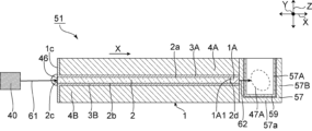
- FIG. 5 is a schematic cross-sectional view showing a microscope kit according to a fourth embodiment of the present invention.
- FIG. 6 is a schematic cross-sectional view showing a modified example of the microscope kit according to the fourth embodiment of the present invention.
- FIG. 1 is a schematic perspective view showing a light guide plate according to a first embodiment of the present invention.
- FIG. 2 is a schematic cross-sectional view of a portion taken along line AA in FIG.
- FIG. 3 is a schematic cross-sectional view showing a light guide plate according to
- FIG. 7 is a schematic cross-sectional view showing a microscope kit according to a fifth embodiment of the present invention.
- FIG. 8 is a schematic cross-sectional view showing a modified example of the microscope kit according to the fifth embodiment of the present invention.
- FIG. 9 is a schematic cross-sectional view showing a modified example of the microscope kit according to the fifth embodiment of the present invention.
- FIG. 10 is a schematic perspective view showing a light guide plate according to a sixth embodiment of the present invention.
- FIG. 11 is a schematic cross-sectional view of a portion taken along line CC in FIG.
- FIG. 12 is a schematic cross-sectional view of a portion taken along line DD in FIG. FIG.
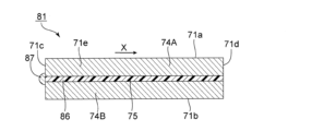
- FIG. 13 is a schematic cross-sectional view showing a first modified example of the light guide plate according to the sixth embodiment of the present invention.
- FIG. 14 is a schematic cross-sectional view showing a second modified example of the light guide plate according to the sixth embodiment of the present invention.
- FIG. 15 is a micrograph of a cell nucleus sample taken using the light guide plate produced in Example 1.
- FIG. 16 is a micrograph of a cell nucleus sample taken using the light guide plate of Comparative Example 2.
- FIG. 1 is a schematic perspective view showing a light guide plate according to a first embodiment of the present invention
- Fig. 2 is a schematic cross-sectional view of a portion taken along line AA in Fig. 1.
- the light guide plate 1 includes a glass sheet 2, a first light absorbing film 3A, a second light absorbing film 3B, a first support member 4A, and a second support member 4B.
- the glass sheet 2 has a rectangular shape in a plan view.
- the shape of the glass sheet 2 may be circular, elliptical, etc. in a plan view, and is not particularly limited.
- the material of the glass sheet 2 is not particularly limited, and examples include quartz glass, soda lime glass, alkali-free glass, aluminosilicate glass, borosilicate glass, etc. These materials may be used alone or in combination.
- the glass sheet 2 has a first main surface 2a and a second main surface 2b that are opposed to each other.
- the glass sheet 2 also has first to fourth end surfaces 2c to 2f that connect the first main surface 2a and the second main surface 2b.
- the first end surface 2c and the second end surface 2d are opposed to each other.
- the third end surface 2e and the fourth end surface 2f are opposed to each other.
- the first end surface 2c of the glass sheet 2 is a light incident surface.
- the second end surface 2d of the glass sheet 2 is a light exit surface.
- the area of each of the first main surface 2a and the second main surface 2b of the glass sheet 2 is not particularly limited, but can be, for example, 100 mm2 or more and 1500 mm2 or less.
- the thickness of the glass sheet 2 is preferably 1 ⁇ m or more, more preferably 3 ⁇ m or more, even more preferably 10 ⁇ m or more, and preferably 100 ⁇ m or less, more preferably 50 ⁇ m or less, and even more preferably 30 ⁇ m or less.
- the thickness of the glass sheet 2 is preferably uniform. For example, when the thickness of the glass sheet 2 is measured at any five points, it is preferable that the difference in thickness of the glass sheet 2 is within 3% of a thickness of 20 ⁇ m.
- Such a glass sheet 2 can be obtained, for example, by a redraw method.
- a first light absorbing film 3A is provided on the first main surface 2a of the glass sheet 2.
- a first support member 4A is provided on the first light absorbing film 3A.
- a second light absorbing film 3B is provided on the second main surface 2b of the glass sheet 2.
- a second support member 4B is provided on the second light absorbing film 3B.
- the first light absorbing film 3A and the second light absorbing film 3B are provided on the first main surface 2a and the second main surface 2b (hereinafter also referred to as main surfaces 2a and 2b) on both sides of the glass sheet 2, and the first support member 4A and the second support member 4B (hereinafter also referred to as support members 4A and 4B) are provided on the light absorbing films 3A and 3B.
- the light absorbing films 3A, 3B are formed on the support members 4A, 4B.
- the light absorbing films 3A, 3B may be formed on the main surfaces 2a, 2b of the glass sheet 2.
- the support members 4A, 4B can be attached to the optical films 3A, 3B or the glass sheet 2 using an adhesive or the like.
- an ultraviolet curing resin or a thermosetting resin can be used as the adhesive.
- the end faces 4Ad, 4Bd of the support members 4A, 4B are arranged on the light output side of the second end face 2d of the glass sheet 2.
- the end faces 3Ad, 3Bd of the light absorbing films 3A, 3B are arranged on the light output side of the second end face 2d of the glass sheet 2.
- a recess 1A is formed on the end face 1d side of the light output side of the light guide plate 1.
- the light absorbing films 3A and 3B preferably have a light absorptance of 90% or more at wavelengths of 400 nm to 650 nm, more preferably 93% or more, even more preferably 95% or more, and particularly preferably 98% or more.
- the upper limit of the light absorptance of the light absorbing films 3A and 3B at wavelengths of 400 nm to 650 nm is not particularly limited, but can be, for example, 100%.
- the light absorbing films 3A and 3B preferably have a reflectance of 4% or less at wavelengths of 400 nm to 650 nm, more preferably 3% or less, even more preferably 2% or less, and particularly preferably 1% or less.
- the lower limit of the reflectance of the light absorbing films 3A and 3B at wavelengths of 400 nm to 650 nm is not particularly limited, but can be, for example, 0.1%.
- the material for such light absorbing films 3A and 3B for example, a material containing carbon or black pigment can be used.
- carbon or black pigment may be contained in silicone resin, acrylic resin, urethane resin, or these synthetic resins.
- the light absorbing films 3A and 3B may be made of different materials, but from the viewpoint of further increasing productivity, it is preferable that the light absorbing films 3A and 3B are made of the same material.
- the light absorbing films 3A and 3B may be light absorbing films composed of at least one element selected from the group consisting of C, Ni, Al, Zn, Co, Fe, and Cu. Furthermore, the light absorbing films 3A and 3B may be light absorbing films composed of a dielectric multilayer film having a high refractive index film with a relatively high refractive index and a low refractive index film with a relatively low refractive index.
- the thickness of the light absorbing films 3A and 3B is preferably 10 nm or more, more preferably 50 nm or more, and is preferably 3 ⁇ m or less, more preferably 1 ⁇ m or less.
- the method for forming the light absorbing films 3A and 3B is not particularly limited, but may be, for example, spray coating, spin coating, or deposition.
- the material of the support members 4A and 4B is not particularly limited, and may be, for example, metal, glass, ceramic, resin, etc.
- the thickness of the support members 4A and 4B is preferably 0.1 mm or more, more preferably 0.5 mm or more, and is preferably 2 mm or less, more preferably 1 mm or less.
- the light guide plate 1 of this embodiment light emitted from the light source enters the glass sheet 2 from the first end face 2c of the glass sheet 2.
- the light travels along the X direction, which is the direction connecting the first end face 2c and the second end face 2d. Furthermore, the light emitted from the second end face 2d is emitted in a sheet shape along the X direction.
- the light absorbing films 3A and 3B are provided on the main surfaces 2a and 2b of the glass sheet 2, so that the light that enters the glass sheet 2 and travels toward the main surfaces 2a and 2b can be absorbed by the light absorbing films 3A and 3B. Therefore, it is possible to suppress the emission of light other than parallel light that directly passes through the glass sheet, and to reduce the components of light other than parallel light among the light emitted from the second end surface 2d of the glass sheet 2. Therefore, it is possible to selectively emit high-quality light from the second end surface 2d. Therefore, when the light guide plate 1 is used in, for example, a light sheet microscope, the resolution can be improved. Therefore, the light guide plate 1 can be suitably used as a microscope kit that constitutes a light sheet microscope, etc.
- the arithmetic mean roughness Ra on the principal surfaces 2a and 2b of the glass sheet 2 is preferably 1000 nm or less, more preferably 100 nm or less, and even more preferably 10 nm or less.
- the lower limit of the arithmetic mean roughness Ra on the principal surfaces 2a and 2b of the glass sheet 2 is not particularly limited, but can be, for example, 0.1 nm.
- the arithmetic mean roughness Ra can be measured in accordance with JIS B 0601:2001.
- the arithmetic mean roughness Ra on the principal surfaces 2a and 2b of the glass sheet 2 can be reduced, for example, by polishing.
- the arithmetic mean roughness Ra of the main surface of the light absorbing films 3A, 3B facing the glass sheet 2 is preferably 100 nm or less, more preferably 10 nm or less, and even more preferably 1 nm or less.
- the light that enters the glass sheet 2 and travels toward the main surfaces 2a, 2b can be more reliably absorbed by the light absorbing films 3A, 3B.
- the lower limit of the arithmetic mean roughness Ra of the main surface of the light absorbing films 3A, 3B facing the glass sheet 2 is not particularly limited, but can be, for example, 0.1 nm.
- the spaces between the principal surfaces 2a, 2b of the glass sheet 2 and the light absorbing films 3A, 3B may be filled with a refractive index matching agent.
- the light that enters the glass sheet 2 and travels toward the principal surfaces 2a, 2b can be more reliably absorbed by the light absorbing films 3A, 3B.
- the refractive index matching agent is not particularly limited, but for example, a refractive index control resin such as an acrylic resin or an epoxy resin can be used.
- the light absorbing films 3A and 3B are provided on the main surfaces 2a and 2b on both sides of the glass sheet 2.
- the first light absorbing film 3A serving as the light absorbing portion may be provided only on the first main surface 2a of the glass sheet 2
- the second light absorbing film 3B serving as the light absorbing portion may be provided only on the second main surface 2b of the glass sheet 2.
- FIG. 3 is a schematic cross-sectional view showing a light guide plate according to a second embodiment of the present invention.
- a first light absorbing film 23A is partially provided on the first main surface 2a of the glass sheet 2. More specifically, the first light absorbing film 23A is partially provided on the second end surface 2d side in the direction connecting the first end surface 2c and the second end surface 2d of the glass sheet 2.
- a first reflective film 25A is partially provided on the first main surface 2a of the glass sheet 2. More specifically, the first reflective film 25A is provided on the first end surface 2c side in the direction connecting the first end surface 2c and the second end surface 2d of the glass sheet 2.
- a second reflective film 25B is provided on the first end surface 2c side, and a second light absorbing film 23B is provided on the second end surface 2d side.
- the material of the first reflective film 25A and the second reflective film 25B (hereinafter also referred to as reflective films 25A and 25B) is not particularly limited, but for example, metals such as Ag, Au, Al, and Cr can be used. One of these materials may be used alone, or two or more types may be used in combination.
- the reflective films 25A and 25B may be made of different materials, but from the viewpoint of further increasing productivity, it is preferable that the reflective films 25A and 25B are made of the same material.
- Reflective films 25A and 25B may also be dielectric multilayer films.
- the dielectric multilayer film a multilayer film including a high refractive index film with a relatively high refractive index and a low refractive index film with a relatively low refractive index can be used. It is preferable that the high refractive index film and the low refractive index film are alternately stacked.
- Materials for the high refractive index film include, for example, niobium oxide, titanium oxide, zirconium oxide, hafnium oxide, tantalum oxide, silicon nitride, aluminum oxide, or aluminum nitride.
- Materials for the low refractive index film include, for example, silicon oxide, aluminum oxide, zirconium oxide, magnesium fluoride, or silicon nitride.
- the material may be appropriately selected so that the refractive index of the low refractive index film is relatively lower than that of the high refractive index film.
- the high refractive index film and the low refractive index film may be formed by, for example, a vapor deposition method or a sputtering method.
- the number of layers of the low refractive index film is not particularly limited, and can be, for example, 1 to 5 layers.
- the number of layers of the high refractive index film is not particularly limited, and can be, for example, 1 to 5 layers.
- the total number of layers of the dielectric multilayer film is not particularly limited, and can be, for example, 2 to 10 layers.
- each low refractive index film layer can be, for example, 5 nm or more and 1000 nm or less.
- the thickness of each high refractive index film layer can be, for example, 5 nm or more and 1000 nm or less.
- the thickness of the entire dielectric multilayer film can be, for example, 10 nm or more and 10,000 nm or less.
- the thickness of the reflective films 25A and 25B is not particularly limited, but can be, for example, 10 nm or more and 200 nm or less.
- the light guide plate 21 also has a first light absorbing film 23A and a second light absorbing film 23B (hereinafter also referred to as light absorbing films 23A and 23B) on the main surfaces 2a and 2b of the glass sheet 2, so that the light that enters the glass sheet 2 and travels toward the main surfaces 2a and 2b can be absorbed by the light absorbing films 23A and 23B. Therefore, the components of light other than the parallel light that directly passes through the glass sheet can be reduced among the light emitted from the second end surface 2d of the glass sheet 2. Therefore, good quality light can be selectively emitted from the second end surface 2d. Therefore, when the light guide plate 21 is used in, for example, a light sheet microscope, the resolution can be improved. Therefore, the light guide plate 21 can be suitably used as a microscope kit that constitutes a light sheet microscope, etc.
- the light guide plate 21 has reflective films 25A and 25B on the first end face 2c side, which is the light incidence surface of the glass sheet 2. This makes it possible to suppress the loss of light that enters the glass sheet 2.
- the reflective films 25A and 25B are formed on the first end face 2c side, which is the light entrance surface of the glass sheet 2, and form the light absorbing films 23A and 23B on the second end face 2d side, which is the light exit surface of the glass sheet 2.
- the ratio of the length of the light absorbing films 23A, 23B (light absorbing portion) in the direction connecting the first end face 2c and the second end face 2d of the glass sheet 2 to the entire length connecting the first end face 2c and the second end face 2d is preferably 0.01 or more, more preferably 0.1 or more, even more preferably 0.2 or more, and preferably 0.4 or less, more preferably 0.3 or less.
- the loss of light incident into the glass sheet 2 can be further suppressed, while the components of light other than the parallel light directly transmitted through the glass sheet can be further reduced among the light emitted from the second end face 2d of the glass sheet 2. Therefore, in this case, when used in a light sheet microscope, the resolution can be further improved.
- the ratio of the length of the light absorbing films 3A, 3B (light absorbing portion) in the direction connecting the first end face 2c and the second end face 2d of the glass sheet 2 to the entire length connecting the first end face 2c and the second end face 2d may be 1.00.
- the light absorbing films 3A and 3B are also provided on the first end face 1c and the second end face 1d of the light guide plate 1, but as in the second embodiment, the light absorbing films do not have to be provided on the first end face 1c and the second end face 1d of the light guide plate 21.
- FIG. 4 is a schematic cross-sectional view showing a light guide plate according to a third embodiment of the present invention.
- a first support member 34A is provided on the first main surface 2a of the glass sheet 2.
- a second support member 34B is provided on the second main surface 2b of the glass sheet 2. Therefore, in this embodiment, the first support member 34A and the second support member 34B (hereinafter also referred to as support members 34A and 34B) are provided directly on the main surfaces 2a and 2b on both sides of the glass sheet 2. Therefore, in the light guide plate 31, a light absorbing film is not provided.
- the light absorption rate of the support members 34A and 34B at wavelengths of 400 nm to 650 nm is preferably 90% or more, more preferably 93% or more, even more preferably 95% or more, and particularly preferably 98% or more.
- the upper limit of the light absorption rate of the support members 34A and 34B at wavelengths of 400 nm to 650 nm is not particularly limited, but can be, for example, 100%.
- the support members 34A and 34B preferably have a reflectance of 4% or less at wavelengths of 400 nm to 650 nm, more preferably 3% or less, even more preferably 2% or less, and particularly preferably 1% or less.
- the lower limit of the reflectance of the light absorbing films 34A and 34B at wavelengths of 400 nm to 650 nm is not particularly limited, but can be, for example, 0.1%.
- Examples of materials for the support members 34A and 34B include glass, resin, metal, ceramic, etc.
- the material for the support members 34A and 34B is preferably glass containing at least one selected from the group consisting of Fe2O3 , CuO, NiO , and Co3O4 . More specific examples of glass include soda - lime glass, alkali-free glass, aluminosilicate glass, borosilicate glass, and phosphate glass.
- phosphate-based glass for example, glass containing, in mass %, 50% to 80% P 2 O 5 , 0% to 10% SiO 2 , 0% to 10% B 2 O 3 , 0% to 10% Al 2 O 3 , 0% to 10% Li 2 O + Na 2 O + K 2 O 0% to 10% MgO + CaO + SrO + BaO 0% to 20% Fe 2 O 3 + CuO + NiO + Co 3 O 4 1% to 30% can be used.
- Li2O + Na2O + K2O refers to the total amount of Li2O , Na2O , and K2O
- MgO+CaO+SrO+BaO refers to the total amount of MgO, CaO, SrO , and BaO
- Fe2O3 +CuO+NiO+ Co3O4 refers to the total amount of Fe2O3 , CuO, NiO , and Co3O4 .
- the support members 34A and 34B may be made of different materials, but from the standpoint of further increasing productivity, it is preferable that the support members 34A and 34B are made of the same material.
- the thickness of the support members 34A, 34B is preferably 0.1 mm or more, more preferably 0.5 mm or more, and is preferably 2 mm or less, more preferably 1 mm or less.
- the thickness of the support members 34A, 34B is equal to or greater than the lower limit, the light absorption ability can be further improved.
- the thickness of the support members 34A, 34B is equal to or less than the upper limit, the light guide plate 31 can be made thinner.
- the support members 34A and 34B are not limited to the above-mentioned materials, and may be made of a material that further enhances the light absorption ability and reduces the thickness of the light guide plate 31.
- the support members 34A and 34B are provided on the main surfaces 2a and 2b of the glass sheet 2, so that the light incident on the glass sheet 2 and traveling toward the main surfaces 2a and 2b can be absorbed by the support members 34A and 34B. Therefore, the components of the light emitted from the second end surface 2d of the glass sheet 2 that are not parallel light that passes directly through the glass sheet can be reduced. Therefore, high-quality light can be selectively emitted from the second end surface 2d. Therefore, when the light guide plate 31 is used in, for example, a light sheet microscope, the resolution can be improved. Therefore, the light guide plate 31 can be suitably used as a microscope kit that constitutes a light sheet microscope, etc.
- the arithmetic mean roughness Ra of the main surfaces of the support members 34A and 34B facing the glass sheet 2 is preferably 100 nm or less, more preferably 10 nm or less, and even more preferably 1 nm or less. In this case, the light that enters the glass sheet 2 and travels toward the main surfaces 2a and 2b can be more reliably absorbed by the support members 34A and 34B.
- the lower limit of the arithmetic mean roughness Ra of the main surfaces of the support members 34A and 34B facing the glass sheet 2 is not particularly limited, but can be, for example, 0.1 nm.
- the spaces between the main surfaces 2a, 2b of the glass sheet 2 and the support members 34A, 34B may be filled with a refractive index matching agent.
- the light that enters the glass sheet 2 and travels toward the main surfaces 2a, 2b can be more reliably absorbed by the support members 34A, 34B.
- the refractive index matching agent is not particularly limited, but for example, a refractive index control resin such as an acrylic resin or an epoxy resin can be used.
- the light absorbing portion may be formed of a light absorbing film as in the first and second embodiments, or the light absorbing portion may be formed of a support member as in the third embodiment.
- FIG. 5 is a schematic cross-sectional view showing a microscope kit according to a fourth embodiment of the present invention.
- Microscope kit 41 is a microscope kit used in a light sheet microscope.
- Microscope kit 41 includes a light guide plate 1 and a cell 47.
- Light guide plate 1 is the light guide plate described in the first embodiment.
- a light source 40 is provided on the light incident side of light guide plate 1.
- an LED light emitting diode
- an LD laser diode
- a lens 46 is provided on end face 1c of the light incident side of light guide plate 1.
- a cell 47 for storing an observation object 47A is provided on the light output side of the light guide plate 1. It is preferable to store one specimen in one cell 47, but multiple specimens may be stored.
- the observation object 47A may be placed in a dedicated solution and observed.
- the dedicated solution for example, a cell transparency solution may be used.
- the recess 1A in the end face 1d on the light output side of the light guide plate 1 is filled with a refractive index matching agent 1A1.
- a refractive index matching agent 1A1 for example, a refractive index control resin such as an acrylic resin or an epoxy resin may be used.
- Cell 47 is made of a transparent material.
- the transparent material that can be used include glass and resin.
- the dimensions of cell 47 can be, for example, a length of 3 mm or more and 5 mm or less, a width of 10 mm or more and 15 mm or less, and a height of 2 mm or more and 4 mm or less.
- the distance between the light guide plate 1 and the cell 47 is preferably adjustable depending on the amount of light of the light guide plate 1 and the size of the object 47A to be observed by the cell 47. This makes it possible to freely move the position of the cell 47 up and down or left and right, etc., relative to the light guide plate 1. For example, in FIG. 5, when the height direction is the Z direction and the direction perpendicular to the X direction and Z direction is the Y direction, it becomes possible to freely move the position of the cell 47 in the X direction, Y direction, Z direction, etc.
- the cell 47 can be attached to the light guide plate 1 via a refractive index matching agent 49. More specifically, an anti-reflection film 48 and a refractive index matching agent 49 can be provided in this order from the end face 1d of the light guide plate 1 between the end face 1d of the light guide plate 1 and the side wall portion 47b1 of the cell 47 on the light guide plate 1 side.
- a dielectric multilayer film can be used as the anti-reflection film 48.
- a dielectric multilayer film including a high refractive index film with a relatively high refractive index and a low refractive index film with a relatively low refractive index can be used. It is preferable that the high refractive index film and the low refractive index film are stacked alternately.
- Materials for the high refractive index film include, for example, niobium oxide, titanium oxide, zirconium oxide, hafnium oxide, tantalum oxide, silicon nitride, aluminum oxide, or aluminum nitride.
- Materials for the low refractive index film include, for example, silicon oxide, aluminum oxide, zirconium oxide, magnesium fluoride, or silicon nitride.
- the material may be appropriately selected so that the refractive index of the low refractive index film is relatively lower than that of the high refractive index film.
- the high refractive index film and the low refractive index film may be formed by, for example, a vapor deposition method or a sputtering method.
- the number of layers of the low refractive index film can be, for example, 1 or more and 5 or less.
- the number of layers of the high refractive index film can be, for example, 1 or more and 5 or less.
- the total number of layers of the dielectric multilayer film can be, for example, 2 or more and 10 or less.
- each low refractive index film layer can be, for example, 5 nm or more and 1000 nm or less.
- the thickness of each high refractive index film layer can be, for example, 5 nm or more and 1000 nm or less.
- the thickness of the entire dielectric multilayer film can be, for example, 2 nm or more and 10,000 nm or less.
- the thickness of the anti-reflection film 48 is preferably 5 nm or more, more preferably 50 nm or more, and is preferably 500 nm or less, more preferably 100 nm or less. In this case, the light incident from the light guide plate 1 can be more effectively taken into the cell 47.
- the refractive index matching agent 49 also has the function of adhering the light guide plate 1 and the cells 47.
- the refractive index matching agent 49 is preferably made of a material with a viscosity that allows the cells 47 to contact the light guide plate 1 while being able to move up and down.
- a refractive index control resin such as an acrylic resin or an epoxy resin can be used as the refractive index matching agent 49.
- the light guide plate 1 may also be in close contact with the cells 47 while being able to move freely up and down or left and right. In this case, for example, in FIG. 6, when the height direction is the Z direction and the direction perpendicular to the X direction and Z direction is the Y direction, the position of the cells 47 can be freely moved in the Y direction, Z direction, etc.
- the thickness of the side wall portion 47b1 of the cell 47 on the light guide plate 1 side is preferably 0.2 mm or less, more preferably 0.15 mm or less, even more preferably 0.1 mm or less, and particularly preferably 0.05 mm or less. In this case, the light incident from the light guide plate 1 can be more effectively taken into the cell 47.
- the lower limit of the thickness of the side wall portion 47b1 of the cell 47 on the light guide plate 1 side is not particularly limited, but can be, for example, 0.02 mm.
- a reflection adjustment film 58 such as an anti-reflection film, a light absorbing film, or a reflection film is provided on the inner surface of the side wall portion 47b2 of the cell 47 opposite the light guide plate 1 to adjust the reflection of light.
- the reflection adjustment film 58 By providing the reflection adjustment film 58, the components of the light reflected on the inner surface of the side wall portion 47b2 can be adjusted, and when used in a light sheet microscope, the resolution can be further improved.
- an anti-reflection film is provided as the reflection adjustment film 58, the same film as the anti-reflection film 48 can be used.
- a light absorbing film such as the light absorbing films 3A and 3B may be provided.
- a reflection film may be provided to provide a desired reflectance.
- the anti-reflection film, the light absorbing film, and the reflection film may be provided on the inner surface of the bottom portion 47a and the entire side wall 47b of the cell 47, except for the side wall portion 47b1.
- light emitted from the light source 40 enters the glass sheet 2 from the first end face 2c of the glass sheet 2 via the lens 46 (incident light 61). Within the glass sheet 2, the light travels along the X direction, which is the direction connecting the first end face 2c and the second end face 2d. Furthermore, the light emitted from the second end face 2d is emitted in a sheet-like form along the X direction (exiting light 62) and enters the cell 47.
- the microscope kits 41 and 41A of this embodiment include a light guide plate 1, so that the components of the light (emitted light 62) emitted from the second end face 2d of the glass sheet 2 that are not parallel light that passes directly through the glass sheet can be reduced. Therefore, high-quality light can be selectively made to enter the cell 47 from the second end face 2d, improving the resolution of the light sheet microscope.
- FIG. 7 is a schematic cross-sectional view showing a microscope kit according to a fifth embodiment of the present invention.
- the light guide plate 1 and the cell 57 are integrally constructed.
- Cell 57 has a double structure, with inner cell 57A in contact with outer cell 57B in a state in which it can move up and down. Inner cell 57A is in contact with outer cell 57B via refractive index matching material 59. As such refractive index matching material 59, the same refractive index matching material 49 described in the fourth embodiment can be used. Other points are the same as those of the fourth embodiment.
- the container of the outer cell 57B may be filled with a viscosity-adjusted refractive index matching agent 59 (for example, the container of the outer cell 57B may be filled with the viscosity-adjusted refractive index matching agent 59 to 50-90% of its height in the Z direction), and the inner cell 57A may be inserted into the portion filled with the refractive index matching agent 59.
- a viscosity-adjusted refractive index matching agent 59 for example, the container of the outer cell 57B may be filled with the viscosity-adjusted refractive index matching agent 59 to 50-90% of its height in the Z direction
- the inner cell 57A may be inserted into the portion filled with the refractive index matching agent 59. This allows the inner cell 57A to be freely movable in the X, Y, and Z directions within the refractive index matching agent 59.
- the outer cell 57B may have a top 57c (top surface perpendicular to the Z direction) without a bottom 57a (lower surface perpendicular to the Z direction).
- the outer cell 57B may not have both a bottom 57a and a top 57c.
- the inner cell 57A contacts the outer cell 57B via a refractive index matching material 59, so that the inner cell 57A can contact the outer cell 57B while being movable up and down.
- the outer cell 57B does not have to have at least one sidewall (a side surface perpendicular to the Y direction).
- the inner cell 57A contacts the outer cell 57B via the refractive index matching material 59, so that the inner cell 57A can be slid into the outer cell 57B from the Y direction.
- both the bottom 57a and the top 57c may be provided, or at least one of the bottom 57a and the top 57c may not be provided.
- the microscope kit 51 of the fifth embodiment also includes a light guide plate 1, so that the components of the light (emitted light 62) emitted from the second end face 2d of the glass sheet 2 that are not parallel light that passes directly through the glass sheet can be reduced. Therefore, high-quality light can be selectively made to enter the cell 57 from the second end face 2d, improving the resolution of the light sheet microscope.
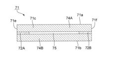
- Fig. 10 is a schematic perspective view showing a light guide plate according to a sixth embodiment of the present invention.
- Fig. 11 is a schematic cross-sectional view of a portion along line CC in Fig. 10.
- Fig. 12 is a schematic cross-sectional view of a portion along line DD in Fig. 10.
- the light guide plate 71 includes a first glass sheet 72A, a second glass sheet 72B, a first support member 74A, and a second support member 74B.
- the light guide plate 71 has a first main surface 71a and a second main surface 71b that face each other.
- the light guide plate 71 also has first to fourth end surfaces 71c to 71f that connect the first main surface 71a and the second main surface 71b.
- the first end surface 71c and the second end surface 71d face each other.
- the third end surface 71e and the fourth end surface 71f face each other.
- the first end surface 71c of the light guide plate 71 is a light entrance surface.
- the second end surface 71d of the light guide plate 71 is a light exit surface.
- the first glass sheet 72A and the second glass sheet 72B are provided between the first support member 74A and the second support member 74B. More specifically, the first glass sheet 72A and the second glass sheet 72B are provided so as to be sandwiched between the first support member 74A and the second support member 74B. The first glass sheet 72A and the second glass sheet 72B function as spacers between the first support member 74A and the second support member 74B.
- the first glass sheet 72A and the second glass sheet 72B are glass sheets having a substantially rectangular planar shape.
- the shapes of the first glass sheet 72A and the second glass sheet 72B are not particularly limited.
- the first glass sheet 72A and the second glass sheet 72B may be, for example, the same as the glass sheet 2 of the first embodiment.
- the first glass sheet 72A is disposed on the third end surface 71e side of the light guide plate 71. More specifically, in a plan view, the long side of the first glass sheet 72A is arranged to be aligned with the third end surface 71e of the light guide plate 71. In this embodiment, in a plan view, the long side of the first glass sheet 72A is arranged to be aligned with the entire third end surface 71e of the light guide plate 71. However, in the present invention, the long side of the first glass sheet 72A may be arranged to be aligned with a portion of the third end surface 71e of the light guide plate 71 in a plan view.
- the second glass sheet 72B is disposed on the fourth end surface 71f side of the light guide plate 71. More specifically, in a plan view, the long side of the second glass sheet 72B is arranged to be aligned with the fourth end surface 71f of the light guide plate 71. In this embodiment, in a plan view, the long side of the second glass sheet 72B is arranged to be aligned with the entire fourth end surface 71f of the light guide plate 71. However, in the present invention, the long side of the second glass sheet 72B may be arranged to be aligned with a portion of the fourth end surface 71f of the light guide plate 71 in a plan view.
- a space 75 is provided between the first glass sheet 72A and the second glass sheet 72B. More specifically, the space 75 is provided so as to be surrounded by the first support member 74A, the second support member 74B, the first glass sheet 72A, and the second glass sheet 72B. Note that in this embodiment, nothing is filled in the space 75, and the space 75 is an air layer.
- the first support member 74A and the second support member 74B are made of the same material as the support members 34A and 34B in the third embodiment described above. Therefore, the first support member 74A and the second support member 74B function as light absorbing parts.
- light emitted from the light source enters the space 75 from the first end face 71c of the light guide plate 71.
- the light travels along the X direction (FIG. 12), which is the direction connecting the first end face 71c and the second end face 71d.
- the light emitted from the second end face 71d is emitted in a sheet shape along the X direction.
- the light guide plate 71 is provided with the first support member 74A and the second support member 74B, the light that enters the space 75 and travels toward the first main surface 71a and the second main surface 71b can be absorbed by the first support member 74A and the second support member 74B. Therefore, the components of the light emitted from the second end surface 71d of the light guide plate 71 that are other than the parallel light that directly passes through the space 75 can be reduced. Therefore, it is possible to selectively emit high-quality light from the second end surface 71d. Therefore, when the light guide plate 71 is used in, for example, a light sheet microscope, the resolution can be improved. Therefore, the light guide plate 71 can be suitably used as a microscope kit that constitutes a light sheet microscope, etc.
- the light guide section (light sheet forming section) may be an air layer. In this case, it is possible to suppress the reflection of light at the light entrance surface (first end surface 71c) and the light exit surface (second end surface 71d) of the light guide plate 71, so that the light can be more efficiently emitted from the second end surface 71d.
- the light guide section (light sheet forming section) is a glass sheet, as in the light guide plates 1, 21, and 31 of the first to third embodiments, it is possible to suppress the diffusion at the light exit surface, and it is possible to emit more uniform light.
- the light guide section (light sheet forming section) is a glass sheet, it is possible to further suppress the occurrence of foreign matter and dirt in the light guide section (light sheet forming section).
- the first glass sheet 72A and the second glass sheet 72B function as spacers provided between the first support member 74A and the second support member 74.
- the first glass sheet 72A and the second glass sheet 72B have a uniform thickness and are less likely to deteriorate over time compared to, for example, a resin sheet or the like. Therefore, the light guide plate 71 can emit uniform light from the second end surface 71d. Furthermore, the light guide plate 71 is also highly reliable.
- the thickness and arithmetic mean roughness Ra of the surface of the first glass sheet 72A and the second glass sheet 72B can be, for example, the same values as those in the column for glass sheet 2.
- the difference in thickness of the glass sheet is within 3% of a thickness of 20 ⁇ m.
- Such a glass sheet can be obtained, for example, by a redraw method.
- the first support member 74A and the second support member 74B themselves are the light absorbing portion, but the light absorbing portion may be configured similarly to the first and second embodiments.
- the light absorbing portion may be configured by providing light absorbing films 3A and 3B on the first support member 74A and the second support member 74B.
- the first support member 74A and the second support member 74B can be configured similarly to the support members 4A and 4B in the first embodiment.
- reflective films 25A and 25B may be provided on the first support member 74A and the second support member 74B on the first end face 71c side, which is the light incident surface.
- a light absorbing film may be provided on the end surface of the first glass sheet 72A and the second glass sheet 72B on the space 75 side.
- the light absorbing film for example, the same as the light absorbing film 3A, 3B of the first embodiment can be used.
- an anti-reflection film may be provided instead of the light absorbing film.
- the same effect as in the case of the light absorbing film can be obtained.
- the anti-reflection film for example, the same as the anti-reflection film 48 of the fourth embodiment can be used.
- the first glass sheet 72A and the second glass sheet 72B themselves may be the light absorbing part.
- the first glass sheet 72A and the second glass sheet 72B can be made of the same material (glass containing at least one selected from the group consisting of Fe2O3 , CuO, NiO, and Co3O4 ) as the first supporting member 74A and the second supporting member 74B.
- a resin, a metal, or a ceramic that can provide the same effect may be used.
- the light guide plate 71 of this embodiment can also be used in a microscope kit.
- the light guide plate 71 can be used instead of the light guide plate 1. Even in this case, it is possible to reduce components of light other than the parallel light that passes directly through the space 75, so that good quality light can be selectively made to enter the cell from the second end face 71d, improving the resolution of the light sheet microscope.
- (Modification of the sixth embodiment) 13 is a schematic cross-sectional view showing a first modified example of the light guide plate according to the sixth embodiment of the present invention.
- a resin 86 is filled in the space 75.
- the resin 86 is a refractive index matching agent.
- the resin 86 is not particularly limited, but can be, for example, a refractive index control resin such as an acrylic resin or an epoxy resin.
- a lens 87 is provided on the first end face 71c, which is the light entrance surface.
- a convex lens may be provided on the light entrance surface to focus the light from the light source.
- another transparent member may be provided on the light entrance surface.
- glass or resin may be provided as the transparent member. Note that, even when the space 75 is an air layer as in the light guide plate 71, a transparent member such as a lens may be provided on at least one of the light entrance surface and the light exit surface.
- the light guide plate 81 also has the first support member 74A and the second support member 74B, the light incident on the resin 86 in the space 75 and traveling toward the first main surface 71a and the second main surface 71b can be absorbed by the first support member 74A and the second support member 74B. Therefore, the light emitted from the second end surface 71d of the light guide plate 81 can be reduced in components other than parallel light that directly passes through the resin 86. Therefore, high-quality light can be selectively emitted from the second end surface 71d. Therefore, when the light guide plate 81 is used in, for example, a light sheet microscope, the resolution can be improved. Therefore, the light guide plate 81 can be suitably used as a microscope kit that constitutes a light sheet microscope, etc.
- FIG. 14 is a schematic cross-sectional view showing a second modified example of a light guide plate according to the sixth embodiment of the present invention.
- the space 75 is filled with a liquid 96.
- the liquid 96 is a refractive index matching agent.
- the liquid 96 is not particularly limited, but for example, a refractive liquid (contact liquid) can be used.
- a lens 97 is provided on the first end face 71c, which is the light incident surface.
- a transparent member 98 is provided on the second end face 71d, which is the light exit surface.
- the light guide plate 91 also has the first support member 74A and the second support member 74B, the light incident on the liquid 96 in the space 75 and traveling toward the first main surface 71a and the second main surface 71b can be absorbed by the first support member 74A and the second support member 74B. Therefore, the light emitted from the second end surface 71d of the light guide plate 91 can be reduced in components other than parallel light that directly passes through the liquid 96. Therefore, high-quality light can be selectively emitted from the second end surface 71d. Therefore, when the light guide plate 91 is used in, for example, a light sheet microscope, the resolution can be improved. Therefore, the light guide plate 91 can be suitably used as a microscope kit that constitutes a light sheet microscope, etc.
- Example 1 As the glass sheet, a glass containing, by mass%, SiO 2 65%, Al 2 O 3 15%, B 2 O 3 10%, MgO 5%, and CaO 5% (light transmittance of 92% at a thickness of 3 mm at a wavelength of 400 nm to 650 nm) was prepared.
- the prepared glass sheet had a length of 14.8 mm, a width of 25.4 mm, and a thickness of 20 ⁇ m. When the thickness of any five points of the prepared glass sheet was measured, the difference in thickness of the glass sheet was within 3% for a thickness of 20 ⁇ m.
- the arithmetic mean roughness Ra of the surface of the glass sheet was 1 nm.
- a pair of glass plates containing, in mass %, 70% P2O5 , 5% SiO2 , 5% BaO, 2% K2O , 1% SrO, 12% NiO, and 5 % Co3O4 were prepared as support members.
- the dimensions of the support members prepared were 15 mm in length, 26 mm in width, and 1 mm in thickness.
- support members were attached to both sides of the prepared glass sheet using an ultraviolet-curing resin as an adhesive so that the glass sheet did not protrude from the support members in a plan view. This resulted in a light guide plate in which both sides of the glass sheet were sandwiched between the support members.
- Example 2 As the glass sheet, a glass having, in mass %, SiO 2 65%, Al 2 O 3 15%, B 2 O 3 10%, MgO 5%, and CaO 5% (light transmittance of 92% at a thickness of 3 mm at a wavelength of 400 nm to 650 nm) was prepared.
- the prepared glass sheet had a length of 14.8 mm, a width of 25.4 mm, and a thickness of 20 ⁇ m. When the thickness of any five points of the prepared glass sheet was measured, the difference in thickness of the glass sheet was within 3% for a thickness of 20 ⁇ m.
- the arithmetic mean roughness Ra of the surface of the glass sheet was 1 nm.
- the optical film was a dielectric multilayer film with a total of 38 layers, in which hafnium oxide and silicon oxide films were alternately stacked, and had a thickness of 1,500 nm.
- Acrylic plates were also prepared as a pair of support members.
- the dimensions of the support members prepared were 15 mm in length, 26 mm in width, and 1 mm in thickness.
- support members were attached to both sides of the prepared glass sheet with optical film using acrylic resin as an adhesive so that the glass sheet with optical film did not protrude from the support members in a plan view. This resulted in a light guide plate in which both sides of the glass sheet with optical film were sandwiched between the support members.
- Example 3 A light guide plate was obtained in the same manner as in Example 1, except that a metal plate (material: SUS304) was used as the support member.
- a metal plate material: SUS304
- Example 4 the light guide plate 71 of the sixth embodiment was produced. Specifically, two sheets of glass containing, by mass%, SiO 2 65%, Al 2 O 3 15%, B 2 O 3 10%, MgO 5%, and CaO 5% (light transmittance of 92% at a thickness of 3 mm at a wavelength of 400 nm to 650 nm) were prepared as glass sheets. The dimensions of the prepared glass sheets were 15 mm long, 2 mm wide, and 20 ⁇ m thick. When the thickness of any five points of the prepared glass sheet was measured, the difference in thickness of the glass sheet was within 3% for a thickness of 20 ⁇ m. The arithmetic mean roughness Ra of the surface of the glass sheet was 1 nm.
- a pair of glass plates (material) having a glass composition of 70 % P2O5 , 5 % SiO2, 5% BaO, 2% K2O , 1% SrO, 12% NiO, and 5% Co3O4 by mass% were prepared as the pair of support members.
- the dimensions of the prepared support members were 15 mm in length, 26 mm in width, and 1 mm in thickness.
- support members were attached to both sides of the two prepared glass sheets using an ultraviolet-curing resin as an adhesive. This resulted in a light guide plate in which both sides of the glass sheets were sandwiched between the support members and a space was created inside.
- Example 1 A light guide plate was obtained in the same manner as in Example 1, except that a resin sheet (material: acrylic resin) was used instead of the glass sheet.
- a resin sheet material: acrylic resin
- Example 2 The same glass sheet as in Example 1 was used as a light guide plate without bonding a support member.
- a spectrophotometer (manufactured by Hitachi High-Tech Science Corporation, product number "UH4150”) was used to measure the light transmission spectrum in the wavelength range of 400 nm to 650 nm of the light absorbing portion of the light guide plate of each Example and Comparative Example 1.
- a near-infrared microspectrometer (manufactured by Olympus Corporation, product number "USPM-RU-W”) was used to measure the reflection spectrum in the wavelength range of 400 nm to 650 nm of the light absorbing portion of each Example and Comparative Example 1. Then, the light absorbance of the light absorbing portion was calculated by subtracting the reflectance from the transmittance in the wavelength range of 400 nm to 650 nm.
- ⁇ Evaluation criteria> No abnormalities in appearance inspection occurred after repeated use. ⁇ : After repeated use, abnormalities in appearance inspection occurred in 20% or less. ⁇ : After repeated use, abnormalities in appearance inspection occurred in 50% to less than 90%. ⁇ : After repeated use, abnormalities in appearance inspection occurred in 90% or more.
- ⁇ Evaluation criteria> ⁇ ...Uniformity of light sheet, no unevenness in intensity. ⁇ ...The uniformity of light sheet is slightly affected by the diffused light from the exit, no unevenness in intensity. ⁇ ...The uniformity of light sheet is affected by the diffused light from the exit, some unevenness in intensity occurs. ⁇ ...The uniformity of light sheet is affected by the diffused light from the exit, some unevenness in intensity occurs.
- the light guide plates of the Examples and Comparative Examples were incorporated into a microscope kit constituting a light sheet microscope, etc., and cell nucleus samples were photographed and subjected to sensory evaluation. Mouse livers stained with DAPI nuclei were used as cell nucleus samples.
- Figure 15 is a micrograph of a cell nucleus sample taken using the light guide plate prepared in Example 1.
- Figure 16 is a micrograph of a cell nucleus sample taken using the light guide plate of Comparative Example 2. As is clear from Figures 15 and 16, the micrograph of the cell nucleus sample taken using the light guide plate prepared in Example 1 has higher resolution and is clearer than that of Comparative Example 2. The micrographs of the cell nucleus samples taken using the light guide plates of the Examples and Comparative Examples were evaluated according to the following evaluation criteria.
Landscapes
- Physics & Mathematics (AREA)
- Chemical & Material Sciences (AREA)
- Analytical Chemistry (AREA)
- General Physics & Mathematics (AREA)
- Optics & Photonics (AREA)
- Optical Elements Other Than Lenses (AREA)
- Planar Illumination Modules (AREA)
- Microscoopes, Condenser (AREA)
- Optical Fibers, Optical Fiber Cores, And Optical Fiber Bundles (AREA)
Priority Applications (3)
| Application Number | Priority Date | Filing Date | Title |
|---|---|---|---|
| DE112024000916.6T DE112024000916T5 (de) | 2023-02-17 | 2024-01-24 | Lichtleiterplatte und mikroskop-bausatz |
| CN202480005976.XA CN120457373A (zh) | 2023-02-17 | 2024-01-24 | 导光板和显微镜套件 |
| JP2025500748A JPWO2024171736A1 (https=) | 2023-02-17 | 2024-01-24 |
Applications Claiming Priority (2)
| Application Number | Priority Date | Filing Date | Title |
|---|---|---|---|
| JP2023-023157 | 2023-02-17 | ||
| JP2023023157 | 2023-02-17 |
Publications (1)
| Publication Number | Publication Date |
|---|---|
| WO2024171736A1 true WO2024171736A1 (ja) | 2024-08-22 |
Family
ID=92421634
Family Applications (1)
| Application Number | Title | Priority Date | Filing Date |
|---|---|---|---|
| PCT/JP2024/001969 Ceased WO2024171736A1 (ja) | 2023-02-17 | 2024-01-24 | 導光板及び顕微鏡キット |
Country Status (5)
| Country | Link |
|---|---|
| JP (1) | JPWO2024171736A1 (https=) |
| CN (1) | CN120457373A (https=) |
| DE (1) | DE112024000916T5 (https=) |
| TW (1) | TW202507375A (https=) |
| WO (1) | WO2024171736A1 (https=) |
Citations (4)
| Publication number | Priority date | Publication date | Assignee | Title |
|---|---|---|---|---|
| US20120293797A1 (en) * | 2009-12-17 | 2012-11-22 | Universiteit Gent | Methods and systems for optical characterisation |
| WO2020204194A1 (ja) * | 2019-04-03 | 2020-10-08 | Agc株式会社 | 光学部材 |
| WO2021210637A1 (ja) * | 2020-04-16 | 2021-10-21 | 国立大学法人東京大学 | 顕微鏡用照明装置、顕微鏡、及び観察方法 |
| WO2022138683A1 (ja) * | 2020-12-22 | 2022-06-30 | Agc株式会社 | 光学素子 |
-
2024
- 2024-01-24 JP JP2025500748A patent/JPWO2024171736A1/ja active Pending
- 2024-01-24 CN CN202480005976.XA patent/CN120457373A/zh active Pending
- 2024-01-24 WO PCT/JP2024/001969 patent/WO2024171736A1/ja not_active Ceased
- 2024-01-24 DE DE112024000916.6T patent/DE112024000916T5/de active Pending
- 2024-02-16 TW TW113105505A patent/TW202507375A/zh unknown
Patent Citations (4)
| Publication number | Priority date | Publication date | Assignee | Title |
|---|---|---|---|---|
| US20120293797A1 (en) * | 2009-12-17 | 2012-11-22 | Universiteit Gent | Methods and systems for optical characterisation |
| WO2020204194A1 (ja) * | 2019-04-03 | 2020-10-08 | Agc株式会社 | 光学部材 |
| WO2021210637A1 (ja) * | 2020-04-16 | 2021-10-21 | 国立大学法人東京大学 | 顕微鏡用照明装置、顕微鏡、及び観察方法 |
| WO2022138683A1 (ja) * | 2020-12-22 | 2022-06-30 | Agc株式会社 | 光学素子 |
Also Published As
| Publication number | Publication date |
|---|---|
| CN120457373A (zh) | 2025-08-08 |
| TW202507375A (zh) | 2025-02-16 |
| JPWO2024171736A1 (https=) | 2024-08-22 |
| DE112024000916T5 (de) | 2025-12-04 |
Similar Documents
| Publication | Publication Date | Title |
|---|---|---|
| JP7222360B2 (ja) | 反射防止膜付ガラス基板及び光学部品 | |
| US20200369560A1 (en) | Cover glass and in-cell liquid-crystal display device | |
| JP6844396B2 (ja) | 紫外線透過フィルタ | |
| US11656456B2 (en) | Optical element and optical apparatus | |
| TWI875698B (zh) | 玻璃基板及光學零件 | |
| EP2657011A1 (en) | Article having low reflection film | |
| TWI850213B (zh) | 光學玻璃及光學構件 | |
| WO2016125792A1 (ja) | 光選択透過型ガラスおよび積層基板 | |
| JP2013148844A (ja) | 光吸収体及びこれを用いた撮像装置 | |
| US20170066681A1 (en) | Glass plate for light guide plate | |
| JP2020109496A (ja) | 光学フィルタおよび近赤外線カットフィルタ | |
| US20170023726A1 (en) | Glass plate for light guide plate | |
| WO2016181864A1 (ja) | ガラス板 | |
| US20210291172A1 (en) | Microfluidic devices and methods for manufacturing microfluidic devices | |
| JP2019525418A (ja) | 積層バックライトユニットのための方法及び装置 | |
| TWI597252B (zh) | 紅外線吸收玻璃晶圓及其製造方法 | |
| JP2025013602A (ja) | 導光板 | |
| US4309078A (en) | Pentagonal prism for camera viewfinder | |
| CN107531540A (zh) | 玻璃板 | |
| JP2017167557A (ja) | 光吸収体及びこれを用いた撮像装置 | |
| US20210333437A1 (en) | Anti-reflective coatings and methods of forming | |
| WO2024171736A1 (ja) | 導光板及び顕微鏡キット | |
| US20230250011A1 (en) | Glass | |
| TW201621367A (zh) | 玻璃及玻璃之製造方法 | |
| JP2023532993A (ja) | 改良された放射線遮蔽ガラス物品 |
Legal Events
| Date | Code | Title | Description |
|---|---|---|---|
| 121 | Ep: the epo has been informed by wipo that ep was designated in this application |
Ref document number: 24756587 Country of ref document: EP Kind code of ref document: A1 |
|
| WWE | Wipo information: entry into national phase |
Ref document number: 2025500748 Country of ref document: JP |
|
| WWE | Wipo information: entry into national phase |
Ref document number: 202480005976.X Country of ref document: CN |
|
| WWP | Wipo information: published in national office |
Ref document number: 202480005976.X Country of ref document: CN |
|
| WWE | Wipo information: entry into national phase |
Ref document number: 112024000916 Country of ref document: DE |
|
| WWP | Wipo information: published in national office |
Ref document number: 112024000916 Country of ref document: DE |
|
| 122 | Ep: pct application non-entry in european phase |
Ref document number: 24756587 Country of ref document: EP Kind code of ref document: A1 |