WO2024171391A1 - セラミックヒータ - Google Patents
セラミックヒータ Download PDFInfo
- Publication number
- WO2024171391A1 WO2024171391A1 PCT/JP2023/005549 JP2023005549W WO2024171391A1 WO 2024171391 A1 WO2024171391 A1 WO 2024171391A1 JP 2023005549 W JP2023005549 W JP 2023005549W WO 2024171391 A1 WO2024171391 A1 WO 2024171391A1
- Authority
- WO
- WIPO (PCT)
- Prior art keywords
- ceramic
- terminal
- plate
- heater
- heater according
- Prior art date
- Legal status (The legal status is an assumption and is not a legal conclusion. Google has not performed a legal analysis and makes no representation as to the accuracy of the status listed.)
- Ceased
Links
Images










Classifications
-
- H—ELECTRICITY
- H10—SEMICONDUCTOR DEVICES; ELECTRIC SOLID-STATE DEVICES NOT OTHERWISE PROVIDED FOR
- H10P—GENERIC PROCESSES OR APPARATUS FOR THE MANUFACTURE OR TREATMENT OF DEVICES COVERED BY CLASS H10
- H10P72/00—Handling or holding of wafers, substrates or devices during manufacture or treatment thereof
- H10P72/70—Handling or holding of wafers, substrates or devices during manufacture or treatment thereof for supporting or gripping
Definitions
- the present invention relates to a ceramic heater, and in particular to a ceramic heater having multiple heating zones.
- Patent Document 1 Japanese Patent No. 6816004 discloses a wafer chuck assembly that includes a pack including an electrically insulating material in which a heater element and multiple electrodes are embedded, a shaft including multiple connectors for the heater element and the electrodes, and a base including an electrically insulating terminal block through which the multiple connectors pass.
- the terminal block serves to align the multiple connectors, and is positioned so that their respective distal ends mate with corresponding sockets in the pack.
- Patent Document 2 JP Patent Publication 2022-122675 discloses a ceramic heater with an inner resistance heating element embedded in the inner region of a ceramic base and an outer resistance heating element embedded in the outer region of the ceramic base.
- An outer power supply terminal that supplies power to the outer resistance heating element is provided in the central region of the ceramic base, while a metal mesh jumper that connects the outer resistance heating element and the outer power supply terminal is embedded in the ceramic base.
- the jumper is composed of a mesh electrode formed by dividing a metal mesh disk on the jumper embedding surface into multiple parts.
- the inner region is a circular region concentric with the ceramic base, and the outer region is an annular region outside the circular region.
- the outer resistance heating element is provided in each of the divided regions obtained by dividing the annular region into multiple parts, or one is provided in the annular region.
- the jumpers are provided to form pairs with each of the outer resistance heating elements.
- a ceramic heater with multiple heating zones as disclosed in Patent Document 2 i.e., a multi-zone heater
- multiple heater electrodes are embedded in the ceramic plate. For this reason, it is necessary to connect a terminal rod to each of these multiple heater electrodes.
- 10 pairs of terminal rods 124 i.e., 20 terminal rods 124 are connected directly or via lead wires 115 to 10 heater electrodes 114 corresponding to each heating zone in the ceramic plate 112.
- the heater electrode 114 is connected to the ceramic shaft 116 through the 20 terminal rods 124 in the internal space S.
- the terminal rods 124 when connecting a large number of terminal rods 124 passing through the ceramic shaft 116 to the heater electrode 114, the terminal rods 124 must be joined individually to the heater electrode 114 or the lead wire 115, making the joining process extremely cumbersome.
- the inventors have now discovered that by connecting a specified multi-terminal integrated structure by soldering to multiple connection parts corresponding to multiple heater electrodes embedded in a ceramic plate, it is possible to simultaneously connect multiple terminal wirings to multiple connection parts while easily ensuring insulation between them.
- the object of the present invention is therefore to provide a highly reliable ceramic heater with multiple heating zones that can be efficiently manufactured by simultaneously joining multiple terminal wires to multiple connection parts while easily ensuring insulation between them.
- a ceramic plate having a first surface for supporting a wafer and a second surface opposite to the first surface, the ceramic plate having a plurality of heater electrodes embedded therein in an arrangement providing a plurality of heating zones; a cylindrical ceramic shaft attached to the second surface of the ceramic plate and having an interior space; a plurality of connection portions formed in an area of the ceramic plate facing the internal space and configured to be connectable to each of the plurality of heater electrodes; a multi-terminal integrated structure disposed in the internal space and connected to the plurality of connection portions;
- a ceramic heater comprising:
- the multi-terminal integral structure is a fixing plate disposed in contact with or adjacent to the second surface of the ceramic plate and spaced from the second surface by a distance of 0 to 50 mm; a plurality of terminal rods fixed and integrated with the fixing plate so as to penetrate the fixing plate in a thickness direction, and one end of each of the terminal rods being soldered to the connecting portions; a plurality of cables,
- Each of the plurality of connection portions is a hole formed in a second surface of the ceramic plate; an exposed portion that is a part of the heater electrode or a part of a lead wire from the heater electrode and is exposed in the hole; and the terminal rod is soldered to the exposed portion.
- a ceramic heater according to aspect 2 wherein an end of the terminal rod is inserted into the hole, and a side surface of the end and an inner wall of the hole are also soldered to each other.
- a ceramic heater according to aspect 2 or 3 wherein the depths of the holes are different from one another in all or some of the plurality of connecting portions.
- the fixing plate is composed of a set of multiple fixing plate pieces each having a shape obtained by dividing a disk-shaped fixing plate, thereby the multi-terminal integral structure is composed of a set of multiple multi-terminal integral structure parts.
- the cable is curved.
- Aspect 16 Aspect 16. The ceramic heater of any one of aspects 1 to 15, wherein the cable extends beyond a lower end of the ceramic shaft.
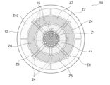
- FIG. 1 is a schematic top view showing one embodiment of a ceramic heater according to the present invention.
- FIG. 2 is a schematic cross-sectional view showing the ceramic heater shown in FIG. 1 .
- 1A to 1C are schematic cross-sectional views for explaining the production of a ceramic heater using a multi-terminal integrated structure.
- FIG. 2 is a schematic cross-sectional view showing an embodiment in which an upper surface of a fixing plate is joined to a ceramic plate.
- FIG. 11 is a schematic cross-sectional view showing another embodiment in which the upper surface of the fixing plate is joined to a ceramic plate.
- FIG. 13 is a schematic cross-sectional view showing one embodiment of an arrangement in which a side surface of a fixed plate is joined to a ceramic shaft.
- FIG. 13 is a schematic cross-sectional view showing one embodiment of an arrangement in which a side surface of a fixed plate is joined to a ceramic plate.
- FIG. 11 is a schematic cross-sectional view showing another embodiment in which the side surface of the fixed plate is joined to the ceramic shaft.
- FIG. 2 is a schematic cross-sectional view showing one embodiment of an arrangement in which the upper surface and side surface of a fixed plate are bonded to a ceramic plate and a ceramic shaft, respectively.
- FIG. 2 is a schematic cross-sectional view showing one embodiment of an arrangement in which the upper surface and side surfaces of a fixing plate are joined to a ceramic plate.
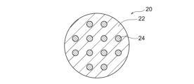
- FIG. 2 is a schematic plan view showing one embodiment of a multi-terminal integrated structure.
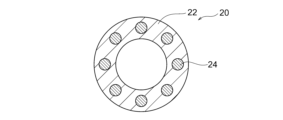
- FIG. 11 is a schematic plan view showing another embodiment of a multi-terminal integrated structure.
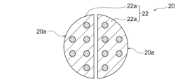
- FIG. 2 is a schematic plan view showing one embodiment of a multi-terminal integrated structure divided linearly.
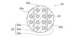
- 13 is a schematic plan view showing another embodiment of a multi-terminal integrated structure divided linearly.
- FIG. 13 is a schematic plan view showing another embodiment of a multi-terminal integrated structure divided linearly.
- FIG. 2 is a schematic plan view showing one embodiment of a multi-terminal integrated structure divided radially.
- 13 is a schematic plan view showing another embodiment of a multi-terminal integrated structure divided radially.
- FIG. 13 is a schematic plan view showing another embodiment of a multi-terminal integrated structure divided radially.
- FIG. 13 is a schematic plan view showing another embodiment of a multi-terminal integrated structure divided radially.
- FIG. 1 is a schematic cross-sectional view showing one embodiment of a ceramic heater, particularly a multi-terminal integrated structure.
- FIG. 11 is a schematic cross-sectional view showing another embodiment of a ceramic heater, particularly a multi-terminal integrated structure.
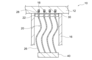
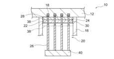
- FIG. 11 is a schematic cross-sectional view showing another embodiment of a ceramic heater, particularly a multi-terminal integrated structure.
- FIG. 1 is a schematic top view showing one embodiment of a ceramic heater according to the prior art.
- FIG. 23 is a schematic cross-sectional view showing the ceramic heater shown in FIG. 22.
- the ceramic heater according to the present invention is a ceramic platform for supporting a wafer in a semiconductor manufacturing device.
- the ceramic heater according to the present invention can be a ceramic heater for a semiconductor film formation device.
- film formation devices include CVD (chemical vapor deposition) devices (e.g., thermal CVD devices, plasma CVD devices, photo CVD devices, and MOCVD devices) and PVD (physical vapor deposition) devices.
- FIGS. 1 and 2 show one embodiment of a ceramic heater.
- the ceramic heater 10 shown in FIGS. 1 and 2 comprises a ceramic plate 12, a cylindrical ceramic shaft 16, a plurality of connection portions 18, and a multi-terminal integral structure 20.
- the ceramic plate 12 has a first surface 12a for mounting a wafer (not shown) and a second surface 12b opposite the first surface 12a.
- a plurality of heater electrodes 14 are embedded in the ceramic plate 12 in an arrangement that provides a plurality of heating zones Z1 to Z10.
- a ceramic shaft 16 is attached to the second surface 12b of the ceramic plate 12.
- the ceramic shaft 16 is cylindrical and therefore has an internal space S.
- connection portions 18 are formed in the area of the ceramic plate 12 facing the internal space S, and these connection portions 18 are configured to be connectable to each of the plurality of heater electrodes 14.
- the multi-terminal integral structure 20 is disposed in the internal space S and is connected to the plurality of connection portions 18.
- the multi-terminal integrated structure 20 includes a fixed plate 22, a plurality of terminal rods 24, and a plurality of cables 26.
- the fixed plate 22 is disposed in contact with or near the second surface 12b of the ceramic plate 12. The distance between the fixed plate 22 and the second surface 12b is 0 to 50 mm.
- the plurality of terminal rods 24 are fixed and integrated with the fixed plate 22 so as to penetrate the fixed plate 22 in the thickness direction, and one end 24a of each of the terminal rods 24 is brazed (using a brazing material 28) to each of the plurality of connection parts 18.
- the other end 24b of each of the plurality of terminal rods 24 is directly or indirectly connected to a plurality of cables 26, each of which is covered with a heat-resistant insulating material.
- a plurality of terminal wirings e.g., terminal rods 24 and cables 26
- this configuration makes it possible to provide a highly reliable ceramic heater 10 with multiple heating zones Z1 to Z10 that can be efficiently manufactured by simultaneously joining multiple terminal wirings to multiple connection parts 18 while easily ensuring insulation between them.
- the terminal rods 124 when connecting a large number of terminal rods 124 passing through the ceramic shaft 116 to the heater electrode 114, the terminal rods 124 must be joined individually to the heater electrode 114 or the lead wire 115, making the joining process extremely cumbersome.
- the multi-terminal integrated structure 20 is placed in contact with or near the ceramic plate 12 and connected to the multiple connection parts 18 by soldering (using solder material 28), which is a simple method that allows multiple terminal wires (e.g., terminal rods 24 and cables 26) to be simultaneously joined to multiple connection parts 18 while easily ensuring insulation between them. That is, the multi-terminal integrated structure 20 has a configuration in which multiple terminal rods 24 are fixed and integrated to the fixed plate 22, and the cables 26 connected to the ends of the terminal rods 24 are covered with a heat-resistant insulating material, so that the multi-terminal integrated structure 20 itself can sufficiently ensure insulation between the terminal wires in advance.
- solder material 28 solder material
- the multi-terminal integrated structure 20 it is not necessary to individually connect the terminal rods 24 to the connection parts 18 one by one, and multiple terminal rods 24 can be simultaneously joined to multiple connection parts 18. Furthermore, even if the joint area decreases with an increase in the number of terminal rods 24, sufficient joint strength can be ensured throughout the multi-terminal integrated structure 20, eliminating the need for strong solder joints as was previously required, and making it possible to use small-diameter terminals with a diameter of 2.0 mm or less.
- the ceramic heater 10 of the present invention has a configuration that allows it to be efficiently manufactured while ensuring sufficient insulation between the terminal wiring and sufficient joint strength between the terminals, and as a result, the ceramic heater 10 can be provided as a highly reliable multi-zone heater.
- the ceramic plate 12 is a ceramic plate in which multiple heater electrodes 14 are embedded in an arrangement that provides multiple heating zones Z1 to Z10.
- the number of heating zones Z is not particularly limited, but is preferably 8 to 150, and more preferably 10 to 50.
- Such a ceramic plate 12 may have a configuration similar to that of a ceramic plate used in a known multi-zone heater (see, for example, Patent Document 2).
- the main parts of the ceramic plate 12 other than the internal electrodes such as the heater electrode 14 and wiring such as the lead wires 15 are preferably made of aluminum nitride, which has excellent thermal conductivity, high electrical insulation, and thermal expansion characteristics similar to those of silicon.
- the preferred shape of the ceramic plate 12 is a disk.
- the planar shape of the disk-shaped ceramic plate 12 does not have to be a perfect circle, and may be an incomplete circle with a portion missing, such as an orientation flat.
- the size of the ceramic plate 12 can be determined appropriately according to the diameter of the wafer for which it is intended to be used, and is not particularly limited, but if it is a circle, the diameter is typically 150 to 450 mm, for example about 300 mm.
- An ESC rod is preferably connected to the ESC electrode for power supply, and the ESC rod is preferably connected to an external power source (not shown) via the internal space S of the ceramic shaft 16.
- the multi-terminal integral structure 20 may further include a terminal rod for the ESC rod.
- the ceramic shaft 16 is a cylindrical shaft attached to the second surface 12b of the ceramic plate 12, and may have the same configuration as ceramic shafts used in known ceramic heaters.
- the ceramic shaft 16 has an internal space S for accommodating the terminal rod 24.
- the ceramic shaft 16 is preferably made of the same ceramic material as the ceramic plate 12. Therefore, the ceramic shaft 16 is preferably made of aluminum nitride.
- the upper end surface of the ceramic shaft 16 is preferably joined to the second surface 12b of the ceramic plate 12 by solid-state bonding or diffusion bonding.
- the outer diameter of the ceramic shaft 16 is not particularly limited, and is, for example, about 40 mm.
- the inner diameter of the ceramic shaft 16 (diameter of the internal space S) is also not particularly limited, and is, for example, about 36 mm.
- connection parts 18 are formed in an area facing the internal space S of the ceramic plate 12 and are configured to be connectable to each of the multiple heater electrodes 14.
- the connection parts 18 are not particularly limited as long as they are configured to allow power to be supplied to the heater electrode 14 by soldering the upper end of the terminal rod 24.
- each of the multiple connection parts 18 has a hole formed in the second surface 12b of the ceramic plate 12, and the terminal rod 24 is soldered to a part of the heater electrode 14 exposed in the hole or a part of the lead wire 15 from the heater electrode 14 (i.e., the exposed part).
- This hole may include not only a hole formed in the ceramic plate 12 but also a recess in the heater electrode 14 and/or the lead wire 15 formed in communication with the hole.
- it is preferable that the end of the terminal rod 24 is inserted into the hole and the side of the end and the inner wall of the hole are also soldered, since the strength can be improved by side joining.
- the depth of the holes may differ from one another in all or part of the multiple connection parts 18. For example, if the heights of the heater electrodes 14 or lead wires 15 differ depending on the corresponding heating zones as shown in FIG. 2, the depth of the holes can be formed to match the respective heights, so that the heater electrodes 14 or lead wires 15 can be appropriately exposed in the holes, and soldering to the connection parts 18 of the terminal rods 24 can be reliably performed.
- the multi-terminal integrated structure 20 is disposed in the internal space S and is connected to the multiple connection portions 18. As shown in Figures 2 and 3, the multi-terminal integrated structure 20 includes a fixed plate 22, multiple terminal rods 24, and multiple cables 26.
- the fixing plate 22 is a plate for fixing and integrating the multiple terminal rods 24 in a state of being insulated from each other. By fixing and integrating the multiple terminal rods 24 to the fixing plate 22, the strength of the fixing plate 22 can be ensured, and therefore the multi-terminal integrated structure 20 as a whole can ensure high strength that cannot be obtained by the terminal rods 24 alone.
- the fixing plate 22 is preferably made of a heat-resistant insulating material, and more preferably one with low thermal conductivity. Examples of such heat-resistant insulating materials include heat-resistant resins such as polyether ether ketone (PEEK), and ceramics such as alumina, aluminum nitride, silicon carbide, titania, and zirconia. In particular, a heat-resistant insulating material having a thermal expansion coefficient equal to or about 50% higher than that of the ceramic plate 12 is preferable, and an example of such a material is AlN-Al 2 O 3 .
- the fixing plate 22 is disposed in contact with or near the second surface 12b of the ceramic plate 12.
- the distance of the fixing plate 22 from the second surface 12b is 0 to 50 mm, preferably 0 to 30 mm.
- the fixing plate 22 is preferably bonded to the ceramic plate 12 and/or the ceramic shaft 16. That is, the fixing of the multi-terminal integrated structure 20 to the ceramic plate 12 can be achieved by soldering the terminal rod 24 to the connection portion 18, but in order to achieve a stronger and more reliable fixation, it is preferable to use a bonding means such as an adhesive 30 (e.g., ceramic bond) to bond to the ceramic plate 12 and/or the ceramic shaft 16.
- a bonding means such as an adhesive 30 (e.g., ceramic bond) to bond to the ceramic plate 12 and/or the ceramic shaft 16.
- the fixing plate 22 can be bonded to various positions of the ceramic plate 12 and/or the ceramic shaft 16.
- Various positional relationships between the fixing plate 22, the ceramic plate 12, and the ceramic shaft 16 are conceptually shown in Figures 4 to 10, omitting other components (terminal rod 24, cable 26, etc.).
- the parts shown as adhesive 30 are the bonded parts, and other parts may not be bonded.
- the fixing plate 22 may be bonded to the second surface 12b of the ceramic plate 12 (or a recess 32 provided in the second surface 12b), or as shown in Figures 6, 8, and 9, the side end surface of the fixing plate 22 may be bonded to the inner wall of the ceramic shaft 16.
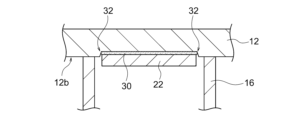
- the second surface 12b of the ceramic plate 12 may have a recess 32 into which at least a part of the fixing plate 22 can be fitted, and the upper surface and/or side end surface of the fixing plate 22 may be bonded to the recess 32.
- Figures 4 and 5 show embodiments in which the upper surface of the fixed plate 22 is joined to the ceramic plate 12 by a joining means such as adhesive 30.
- the fixed plate 22 is joined only to the second surface 12b of the ceramic plate 12 by adhesive 30.
- the fixed plate 22 is joined only to the recess 32 of the ceramic plate 12 by adhesive 30. In either embodiment, it is sufficient that the fixed plate 22 is joined to the ceramic plate 12 only at its upper surface, and the side end surfaces of the fixed plate 22 do not need to be joined to the ceramic plate 12 and the ceramic shaft 16.
- the presence of a gap in the lateral direction of the fixing plate 22 makes it possible to prevent members with different thermal expansion coefficients from coming into contact with each other in the lateral direction, thereby preventing the occurrence of such lateral compressive stress. Even if members with different expansion coefficients come into contact with each other in the lateral direction, the stress is absorbed or alleviated by the gap as a buffer space, so that the lateral compressive stress can be reduced.
- FIG. 6 to 8 show an embodiment in which the side end surface of the fixed plate 22 is joined to the ceramic shaft 16 or the ceramic plate 12 by a joining means such as adhesive 30.
- the fixed plate 22 is joined only to the inner wall of the ceramic shaft 16 by adhesive 30.
- the side end surface of the fixed plate 22 is joined only to a recess 32 provided in the second surface 12b of the ceramic plate 12 by adhesive 30.
- the fixed plate 22 only needs to be joined to the ceramic shaft 16 or the ceramic plate 12 at its side end surface, and the upper surface of the fixed plate 22 does not need to be joined to the ceramic plate 12 and the ceramic shaft 16. Therefore, as in the embodiment shown in FIG.
- the side end surface of the fixed plate 22 may be joined to the ceramic shaft 16 with a gap between the ceramic plate 12 and the fixed plate 22.
- a cutout portion may be provided in the ceramic shaft 16, and the side end portion of the fixed plate 22 may be supported by this cutout portion.
- a gap can be provided between the fixed plate 22 and the ceramic shaft 16, or between the side end face of the fixed plate 22 and the inner wall of the recess 32 of the ceramic plate 12. That is, by only partially bonding the fixed plate 22 and the ceramic shaft 16 with the adhesive 30, a gap can be provided at the non-bonded portion between the fixed plate 22 and the ceramic shaft 16. Similarly, by only partially bonding the side end face of the fixed plate 22 and the inner wall of the recess 32 with the adhesive 30, a gap can be provided at the non-bonded portion between the side end face of the fixed plate 22 and the inner wall of the recess 32. Then, such a gap can be made to function as a buffer space for relieving lateral stress as described above.
- this gap can function as an insulating space, and the insulating properties of the multi-terminal integrated structure 20 can be improved. Furthermore, the improved insulating properties make it possible to adjust the amount of expansion and contraction of members with different expansion coefficients, and the horizontal stress can be reduced. That is, even if the thermal expansion coefficient of the fixed plate 22 is greater than that of the ceramic plate 12, the temperature of the fixed plate 22 can be lowered due to the improved insulating properties, and the stress due to the difference in the thermal expansion coefficients of the two members can be reduced. Furthermore, this gap can also function as a buffer space for alleviating vertical stress.
- FIG. 9 and 10 show an embodiment in which the upper surface and side end surfaces of the fixing plate 22 are bonded to the ceramic shaft 16 or ceramic plate 12.
- the upper surface and side end surfaces of the fixing plate 22 are bonded to the second surface 12b of the ceramic plate 12 and the inner wall of the ceramic shaft 16, respectively, by a bonding means such as adhesive 30.
- the upper surface and side end surfaces of the fixing plate 22 are bonded to the recess 32 of the ceramic plate 12 by adhesive 30.
- the upper surface and side end surfaces of the fixing plate 22 do not need to be bonded to the ceramic plate 12 or ceramic shaft 16 in their entirety, and there may be some portions that are not bonded.
- bonding can be performed over a wider area, improving the adhesive strength.
- the terminal rod 24 can be further reduced in diameter.
- a gap may exist between the second surface 12b of the ceramic plate 12 and the fixed plate 22 (see FIG. 8). Also, a gap may exist between the side end surface of the fixed plate 22 and the inner wall of the ceramic shaft 16 (see FIGS. 4, 5, 7, and 10), or no gap may exist between the side end surface of the fixed plate 22 and the inner wall of the ceramic shaft 16 (see FIGS. 6, 8, and 9).
- the fixing plate 22 or the multi-terminal integrated structure 20 is not particularly limited in shape as long as it can be accommodated in the internal space S of the ceramic shaft 16, but it is preferable that the fixing plate 22 or the multi-terminal integrated structure 20 is disk-shaped as shown in FIG. 11, or annular as shown in FIG. 12. These shapes are suitable for the cylindrical ceramic shaft 16, and allow many terminal rods 24 to be fixed by efficiently utilizing the internal space S of the ceramic shaft 16.
- the fixing plate 22 may be composed of a set of multiple fixing plate pieces 22a in the shape of a divided disk-shaped fixing plate 22, as shown in Figures 13 to 18, and the multi-terminal integrated structure 20 may be composed of a set of multiple multi-terminal integrated structure parts 20a.
- the terminal joining work of the multi-terminal integrated structure 20 can be performed by dividing each divided multi-terminal integrated structure part 20a, so that the terminal joining work can be simplified.
- the fixing plate 22 or the multi-terminal integrated structure 20 may be linearly divided into two equal parts as shown in Figure 13, or may be linearly divided at an arbitrary position (not limited to being divided into two equal parts) as shown in Figure 14.
- the fixing plate 22 or the multi-terminal integrated structure 20 may be radially divided into four equal parts as shown in Figure 16, or may be radially divided at an arbitrary ratio as shown in Figures 17 and 18.
- the number of fixing plate pieces 22a that make up the fixing plate 22 is not particularly limited, but is preferably 2 to 8, and more preferably 2 to 4.
- the terminal rods 24 are fixed and integrated with the fixed plate 22 so as to penetrate the fixed plate 22 in the thickness direction.
- One end of each of the terminal rods 24 is soldered to each of the connection parts 18, while the other end of each of the terminal rods 24 is directly or indirectly connected to a cable 26 (described later) and can be connected to a heater power source (not shown) via the cable 26 (or the metal wire 34 and the cable 26).
- This configuration ensures a power supply path to the heater electrode 14.
- the terminal rods 24 are not particularly limited as long as they are conductive members, and can be made of metals such as molybdenum and nickel, but are preferably made of molybdenum from the viewpoint of thermal expansion coefficient.
- the diameter of the terminal rods 24 is not particularly limited, but is preferably 0.5 to 5 mm, and more preferably 1 to 3 mm. Within these ranges, the joint strength between the terminal rods 24 and the connection parts 18 can be sufficiently ensured even when the number of terminal rods 24 is increased.
- the number of terminal rods 24 is not particularly limited, but from the perspective of use as a multi-zone heater, it is preferably 16 to 300, and more preferably 20 to 100.
- the diameter of the terminal rod 24 connected to one of the heater electrodes 14 may be different from the diameter of the terminal rod 24 connected to the other of the heater electrodes 14 so as to allow different amounts of current depending on the heater electrodes 14.
- the number of terminal rods 24 connected to one of the heater electrodes 14 may be different from the number of terminal rods 24 connected to the other of the heater electrodes 14 so as to allow different amounts of current depending on the heater electrodes 14. Since the ceramic heater 10 of the present invention has multiple heating zones Z1 to Z10, it is possible to provide a desirable heater function as a multi-zone heater by changing the amount of current to be supplied to the heater electrodes 14 depending on the heating zone.
- the heater electrodes 14 corresponding to the heating zones Z1 to Z10 may include a main heater electrode and a sub-heater electrode, and a configuration may be used in which more current is supplied to the main heater electrode than to the sub-heater electrode.
- the multiple cables 26 are directly or indirectly connected (through other members such as metal wires 34 described later) to the other ends of the multiple terminal rods 24.
- Each cable 26 is covered with a heat-resistant insulating material. This ensures that the terminal wires are insulated from each other, facilitating assembly of the ceramic heater 10 (particularly connection to the connection portion 18 of the multi-terminal integrated structure 20).
- the cable 26 covered with a heat-resistant insulating material has heat resistance (e.g., the ability to withstand high temperatures of 500°C) that can withstand being placed near the ceramic plate 12 that is heated to high temperatures (e.g., 600°C or higher).
- heat-resistant insulating materials used to cover the cable 26 include silica glass, mica, and high heat-resistant resins (e.g., polytetrafluoroethylene (PTFE)).
- the core portion of the cable 26 other than the covered portion is preferably a metal wire.
- the metal wire is not particularly limited as long as it is a conductive member, and may be any metal commonly used as a cable material.
- the cable 26 may be a metal wire covered with an insulating tube made of a heat-resistant insulating material.
- the ceramic heater 10 of the present invention is provided with a multi-terminal integrated structure 20, which allows for desirable control of heat dissipation and insulation within the ceramic shaft 16.
- a multi-terminal integrated structure 20 which allows for desirable control of heat dissipation and insulation within the ceramic shaft 16.
- the multi-terminal integrated structure 20 is configured so that it is possible to desirably control the heat dissipation and insulation within the ceramic shaft 16.
- Various preferred embodiments suitable for such heat dissipation and insulation are shown in Figures 19 to 21.
- the cable 26 is curved as shown in FIG. 19 (and FIG. 2).
- the length of the cable 26 can be made longer than the length of the ceramic shaft 16.
- the surface area of the cable 26 within the ceramic shaft 16 is increased, and heat dissipation into the ceramic shaft 16 can be promoted. In this way, heat conduction to the device component 40 located at or below the lower end of the ceramic shaft 16 can be suppressed, and the risk of damage to the device component 40 due to thermal deterioration can be reduced.
- the multi-terminal integrated structure 20 further includes an exposed metal wire 34 that is not covered with a heat-resistant insulating material and is interposed between the terminal rod 24 and the cable 26.
- the exposed metal wire 34 is surrounded by an insulating protective material 36 that has a lower thermal conductivity than the metal wire 34. In this way, by providing the exposed metal wire 34 and the insulating protective material 36 in the internal space S of the ceramic shaft 16, heat dissipation from the exposed metal wire 34 to the internal space S of the ceramic shaft 16 can be promoted.
- the exposed metal wire 34 with high thermal conductivity promotes heat dissipation, while the metal wire 34 is surrounded by the insulating protective material 36 to ensure insulation between the metal wires 34.
- the thermal conductivity of the metal wire 34 is higher than that of the insulating protective material 36.
- the metal wire 34 is not particularly limited as long as it is a conductive material, but may be a metal that is generally used as a cable material.
- the insulating protective material 36 is not particularly limited as long as it is a material that can insulate the metal wires 34 from each other, but preferred examples include aluminum nitride and alumina. From the viewpoint of promoting heat dissipation of the metal wire 34, it is preferable that the insulating protective material 36 is configured in a tubular shape so as to provide a space for heat dissipation around the metal wire 34.
- a heat insulating member 38 may be further provided between the ceramic plate 12 and the fixed plate 22 and/or on the side of the fixed plate 22 opposite the ceramic plate 12. That is, in FIG. 21, the heat insulating member 38 is provided between the ceramic plate 12 and the fixed plate 22, but the heat insulating member 38 may be provided on the side of the fixed plate 22 opposite the ceramic plate 12 as depicted by the dotted line in the figure. In that case, it is preferable that the heat insulating member 38 is provided at or near the lower end of the terminal rod 24 extending downward from the fixed plate 22 (for example, so that the lower end of the terminal rod 24 is hidden).
- the heat insulating member 38 may be provided on both sides of the fixed plate 22.
- the heat insulating member 38 By providing the heat insulating member 38 on the upper side, lower side, or both sides of the fixed plate 22, heat conduction downward from the fixed plate 22 can be suppressed.
- the heat insulating member 38 may be bonded to the terminal rod 24 in advance, in which case assembly of the heat insulating member 38 and the terminal rod 24 becomes easier.
- the heat insulating member 38 is not particularly limited as long as it is a plate-shaped member having heat resistance, heat insulation, and electrical insulation properties, but preferred examples include zirconia or alumina.
- the cable 26 extends beyond the lower end of the ceramic shaft 16. This can further enhance the heat dissipation effect of the cable 26 located below the fixing plate 22, and more effectively reduce the risk of damage due to thermal degradation of the device components 40.
- the cable 26 disposed below the fixed plate 22 can be cooled without cooling the fixed plate 22 and the terminal rod 24 extending therefrom toward the connection portion 18.
- a cooling means for cooling the multi-terminal integrated structure 20 or the fixed plate 22 may be provided in the ceramic shaft 16.
Landscapes
- Resistance Heating (AREA)
Priority Applications (2)
| Application Number | Priority Date | Filing Date | Title |
|---|---|---|---|
| PCT/JP2023/005549 WO2024171391A1 (ja) | 2023-02-16 | 2023-02-16 | セラミックヒータ |
| JP2023551769A JP7598480B1 (ja) | 2023-02-16 | 2023-02-16 | セラミックヒータ |
Applications Claiming Priority (1)
| Application Number | Priority Date | Filing Date | Title |
|---|---|---|---|
| PCT/JP2023/005549 WO2024171391A1 (ja) | 2023-02-16 | 2023-02-16 | セラミックヒータ |
Publications (1)
| Publication Number | Publication Date |
|---|---|
| WO2024171391A1 true WO2024171391A1 (ja) | 2024-08-22 |
Family
ID=92421128
Family Applications (1)
| Application Number | Title | Priority Date | Filing Date |
|---|---|---|---|
| PCT/JP2023/005549 Ceased WO2024171391A1 (ja) | 2023-02-16 | 2023-02-16 | セラミックヒータ |
Country Status (2)
| Country | Link |
|---|---|
| JP (1) | JP7598480B1 (https=) |
| WO (1) | WO2024171391A1 (https=) |
Citations (7)
| Publication number | Priority date | Publication date | Assignee | Title |
|---|---|---|---|---|
| KR20070069463A (ko) * | 2005-12-28 | 2007-07-03 | 주식회사 코미코 | 정전척 및 히터 |
| US20160002779A1 (en) * | 2014-07-02 | 2016-01-07 | Applied Materials, Inc. | Multi-zone pedestal for plasma processing |
| JP2017228360A (ja) * | 2016-06-20 | 2017-12-28 | 日本特殊陶業株式会社 | 加熱部材及び静電チャック |
| JP2018056332A (ja) * | 2016-09-29 | 2018-04-05 | 日本特殊陶業株式会社 | 加熱装置 |
| JP2019220537A (ja) * | 2018-06-19 | 2019-12-26 | 日本特殊陶業株式会社 | 保持装置 |
| JP3233344U (ja) * | 2020-05-29 | 2021-08-05 | アプライド マテリアルズ インコーポレイテッドApplied Materials,Incorporated | 冷却された基板支持アセンブリのための電気コネクタ |
| JP2022124055A (ja) * | 2021-02-15 | 2022-08-25 | 日本特殊陶業株式会社 | 電極埋設部材及び半導体製造装置部品 |
Family Cites Families (2)
| Publication number | Priority date | Publication date | Assignee | Title |
|---|---|---|---|---|
| JP2005032842A (ja) * | 2003-07-08 | 2005-02-03 | Ibiden Co Ltd | 電極構造およびセラミック接合体 |
| JP7430617B2 (ja) * | 2020-10-16 | 2024-02-13 | 日本碍子株式会社 | ウエハ載置台 |
-
2023
- 2023-02-16 JP JP2023551769A patent/JP7598480B1/ja active Active
- 2023-02-16 WO PCT/JP2023/005549 patent/WO2024171391A1/ja not_active Ceased
Patent Citations (7)
| Publication number | Priority date | Publication date | Assignee | Title |
|---|---|---|---|---|
| KR20070069463A (ko) * | 2005-12-28 | 2007-07-03 | 주식회사 코미코 | 정전척 및 히터 |
| US20160002779A1 (en) * | 2014-07-02 | 2016-01-07 | Applied Materials, Inc. | Multi-zone pedestal for plasma processing |
| JP2017228360A (ja) * | 2016-06-20 | 2017-12-28 | 日本特殊陶業株式会社 | 加熱部材及び静電チャック |
| JP2018056332A (ja) * | 2016-09-29 | 2018-04-05 | 日本特殊陶業株式会社 | 加熱装置 |
| JP2019220537A (ja) * | 2018-06-19 | 2019-12-26 | 日本特殊陶業株式会社 | 保持装置 |
| JP3233344U (ja) * | 2020-05-29 | 2021-08-05 | アプライド マテリアルズ インコーポレイテッドApplied Materials,Incorporated | 冷却された基板支持アセンブリのための電気コネクタ |
| JP2022124055A (ja) * | 2021-02-15 | 2022-08-25 | 日本特殊陶業株式会社 | 電極埋設部材及び半導体製造装置部品 |
Also Published As
| Publication number | Publication date |
|---|---|
| JPWO2024171391A1 (https=) | 2024-08-22 |
| JP7598480B1 (ja) | 2024-12-11 |
Similar Documents
| Publication | Publication Date | Title |
|---|---|---|
| JP6341457B1 (ja) | 静電チャック | |
| JP6463938B2 (ja) | 静電チャック | |
| JP5554525B2 (ja) | 静電チャック | |
| JP6428456B2 (ja) | 静電チャック装置 | |
| KR100497016B1 (ko) | 가열 장치 | |
| KR101333631B1 (ko) | 퀄츠 히터 | |
| US12150215B2 (en) | Wafer placement table | |
| KR102254204B1 (ko) | 세라믹 히터 | |
| KR100512350B1 (ko) | 세라믹 히터 | |
| JP6317183B2 (ja) | 半導体製造装置用部品 | |
| KR101585082B1 (ko) | 히팅 유닛 및 그 제조방법 및 이를 이용한 온도 제어가 가능한 정전척 | |
| JP2018045920A (ja) | セラミックヒータ及びその製造方法。 | |
| KR20230030050A (ko) | 유지 장치 | |
| KR102150811B1 (ko) | 세라믹스 히터 | |
| TWI859403B (zh) | 靜電夾盤及基板固定裝置 | |
| JP2007088484A (ja) | 加熱装置 | |
| JP7598480B1 (ja) | セラミックヒータ | |
| JP2018005998A (ja) | セラミックスヒータ | |
| JP7795875B2 (ja) | 保持装置 | |
| KR101593557B1 (ko) | 하이브리드 정전척 및 그 제조방법 | |
| KR101904490B1 (ko) | 세라믹 히터 접합구조 | |
| US12108498B2 (en) | Wafer placement table | |
| JP2021190603A (ja) | 保持装置 | |
| KR100979915B1 (ko) | 정전척 및 히터 | |
| JP7489940B2 (ja) | 試料保持具 |
Legal Events
| Date | Code | Title | Description |
|---|---|---|---|
| WWE | Wipo information: entry into national phase |
Ref document number: 2023551769 Country of ref document: JP |
|
| 121 | Ep: the epo has been informed by wipo that ep was designated in this application |
Ref document number: 23922727 Country of ref document: EP Kind code of ref document: A1 |
|
| NENP | Non-entry into the national phase |
Ref country code: DE |
|
| 122 | Ep: pct application non-entry in european phase |
Ref document number: 23922727 Country of ref document: EP Kind code of ref document: A1 |