WO2024166946A1 - 光ファイバケーブル及び光ファイバユニット - Google Patents
光ファイバケーブル及び光ファイバユニット Download PDFInfo
- Publication number
- WO2024166946A1 WO2024166946A1 PCT/JP2024/004114 JP2024004114W WO2024166946A1 WO 2024166946 A1 WO2024166946 A1 WO 2024166946A1 JP 2024004114 W JP2024004114 W JP 2024004114W WO 2024166946 A1 WO2024166946 A1 WO 2024166946A1
- Authority
- WO
- WIPO (PCT)
- Prior art keywords
- optical fiber
- water
- cores
- absorbent
- ribbons
- Prior art date
- Legal status (The legal status is an assumption and is not a legal conclusion. Google has not performed a legal analysis and makes no representation as to the accuracy of the status listed.)
- Ceased
Links
Images


Classifications
-
- G—PHYSICS
- G02—OPTICS
- G02B—OPTICAL ELEMENTS, SYSTEMS OR APPARATUS
- G02B6/00—Light guides; Structural details of arrangements comprising light guides and other optical elements, e.g. couplings
- G02B6/44—Mechanical structures for providing tensile strength and external protection for fibres, e.g. optical transmission cables
- G02B6/4401—Optical cables
- G02B6/4429—Means specially adapted for strengthening or protecting the cables
- G02B6/44384—Means specially adapted for strengthening or protecting the cables the means comprising water blocking or hydrophobic materials
-
- G—PHYSICS
- G02—OPTICS
- G02B—OPTICAL ELEMENTS, SYSTEMS OR APPARATUS
- G02B6/00—Light guides; Structural details of arrangements comprising light guides and other optical elements, e.g. couplings
- G02B6/44—Mechanical structures for providing tensile strength and external protection for fibres, e.g. optical transmission cables
- G02B6/4401—Optical cables
- G02B6/4403—Optical cables with ribbon structure
- G02B6/4404—Multi-podded
-
- G—PHYSICS
- G02—OPTICS
- G02B—OPTICAL ELEMENTS, SYSTEMS OR APPARATUS
- G02B6/00—Light guides; Structural details of arrangements comprising light guides and other optical elements, e.g. couplings
- G02B6/44—Mechanical structures for providing tensile strength and external protection for fibres, e.g. optical transmission cables
- G02B6/4401—Optical cables
- G02B6/441—Optical cables built up from sub-bundles
-
- G—PHYSICS
- G02—OPTICS
- G02B—OPTICAL ELEMENTS, SYSTEMS OR APPARATUS
- G02B6/00—Light guides; Structural details of arrangements comprising light guides and other optical elements, e.g. couplings
- G02B6/44—Mechanical structures for providing tensile strength and external protection for fibres, e.g. optical transmission cables
- G02B6/4401—Optical cables
- G02B6/4415—Cables for special applications
- G02B6/4427—Pressure resistant cables, e.g. undersea cables
-
- G—PHYSICS
- G02—OPTICS
- G02B—OPTICAL ELEMENTS, SYSTEMS OR APPARATUS
- G02B6/00—Light guides; Structural details of arrangements comprising light guides and other optical elements, e.g. couplings
- G02B6/44—Mechanical structures for providing tensile strength and external protection for fibres, e.g. optical transmission cables
- G02B6/4401—Optical cables
- G02B6/4429—Means specially adapted for strengthening or protecting the cables
- G02B6/443—Protective covering
- G02B6/4431—Protective covering with provision in the protective covering, e.g. weak line, for gaining access to one or more fibres, e.g. for branching or tapping
-
- G—PHYSICS
- G02—OPTICS
- G02B—OPTICAL ELEMENTS, SYSTEMS OR APPARATUS
- G02B6/00—Light guides; Structural details of arrangements comprising light guides and other optical elements, e.g. couplings
- G02B6/44—Mechanical structures for providing tensile strength and external protection for fibres, e.g. optical transmission cables
- G02B6/4401—Optical cables
- G02B6/4429—Means specially adapted for strengthening or protecting the cables
- G02B6/443—Protective covering
- G02B6/4432—Protective covering with fibre reinforcements
- G02B6/4433—Double reinforcement laying in straight line with optical transmission element
Definitions
- the present disclosure relates to fiber optic cables and fiber optic units.
- This application claims priority based on Japanese Application No. 2023-017611 filed on February 8, 2023, and incorporates by reference all of the contents of the above-mentioned Japanese application.
- Patent Document 1 discloses an optical fiber cable equipped with an optical fiber unit assembly, which is an assembly of multiple optical fiber units, each of which is made up of multiple bundled optical fiber cores.
- the optical fiber cable disclosed in Patent Document 1 is equipped with an external water-stopping material provided on the outer periphery of the optical fiber unit assembly, and an internal water-stopping material provided inside the optical fiber unit assembly.
- the internal water-stopping material is a water-swellable fiber or string-like member.
- Fiber optic cables are A plurality of optical fiber ribbons; A plurality of water-absorbent members; a jacket that covers the plurality of optical fiber ribbons and the plurality of water-absorbent members;
- Each of the optical fiber ribbons is A plurality of optical fiber cores; a connecting resin that connects the plurality of optical fiber cores arranged in parallel in a direction perpendicular to the longitudinal direction of the plurality of optical fiber cores, The connecting resin has at least one recess between adjacent optical fibers, The thickness of each of the water-absorbent members is smaller than the center-to-center distance between two adjacent optical fibers in the parallel arrangement direction of the optical fibers.
- the optical fiber unit is one or more optical fiber ribbons; A plurality of water-absorbent members; a unit covering portion that covers the one or more optical fiber ribbons and the plurality of water-absorbent members;
- Each of the optical fiber ribbons is A plurality of optical fiber cores; a connecting resin that connects the plurality of optical fiber cores arranged in parallel in a direction perpendicular to the longitudinal direction of the plurality of optical fiber cores, The connecting resin has at least one recess between adjacent optical fibers, The thickness of each of the water-absorbent members is smaller than the center-to-center distance between two adjacent optical fibers in the parallel arrangement direction of the optical fibers.
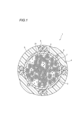
- FIG. 1 is a cross-sectional view perpendicular to the longitudinal direction of an optical fiber cable according to a first embodiment.
- FIG. 2 is a partial development view showing an optical fiber ribbon used in an optical fiber cable in the longitudinal direction.
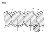
- FIG. 3 is a partially enlarged cross-sectional view perpendicular to the longitudinal direction of some of the optical fiber cores among the multiple optical fiber cores that form the optical fiber ribbon.
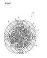
- FIG. 4 is a cross-sectional view perpendicular to the longitudinal direction of an optical fiber cable according to a modified example of the first embodiment.
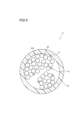
- FIG. 5 is a cross-sectional view perpendicular to the longitudinal direction of the optical fiber unit according to the second embodiment.
- FIG. 6 is a schematic diagram for explaining an evaluation experiment of the waterproofing property of an optical fiber cable.
- an optical fiber ribbon As an optical fiber core wire mounted in an optical fiber cable, an optical fiber ribbon is known that has a plurality of optical fiber core wires and a connecting resin that connects the optical fiber core wires arranged in parallel in a direction perpendicular to the longitudinal direction of the optical fiber core wires. Water that has entered the cable may run in the longitudinal direction along the connecting resin. In particular, when the optical fiber ribbon has a recess between adjacent optical fiber core wires, water may run a longer distance along the recess.
- the present disclosure aims to provide optical fiber cables and optical fiber units with improved waterproofing.
- An optical fiber cable A plurality of optical fiber ribbons; A plurality of water-absorbent members; a jacket that covers the plurality of optical fiber ribbons and the plurality of water-absorbent members;
- Each of the optical fiber ribbons is A plurality of optical fiber cores; a connecting resin that connects the plurality of optical fiber cores arranged in parallel in a direction perpendicular to the longitudinal direction of the plurality of optical fiber cores, The connecting resin has at least one recess between adjacent optical fibers, The thickness of each of the water-absorbent members is smaller than the center-to-center distance between two adjacent optical fibers in the parallel arrangement direction of the optical fibers.
- the connecting resin of each optical fiber ribbon has at least one recess between adjacent optical fiber cores, making it easy to separate some optical fiber cores from the optical fiber ribbon and mount the optical fiber cores in the cable.
- Water that has entered the optical fiber cable is likely to run long along the longitudinal direction by flowing along this recess.
- the thickness of each water-absorbing member disclosed herein is smaller than the center-to-center distance between two adjacent optical fiber cores in the parallel direction of the optical fiber cores. As the size of the water-absorbing member allows it to easily enter the recess, water running inside the cable can be suppressed.
- the optical fiber ribbon may be an intermittently connected optical fiber ribbon in which, among some or all of the optical fiber cores, connected sections in which adjacent optical fiber cores are connected and non-connected sections in which adjacent optical fiber cores are not connected are alternately provided in the longitudinal direction.
- the optical fiber ribbons When the optical fiber ribbons are intermittently connected optical fiber ribbons, they can be stored at high density within the optical fiber cable. However, if there are recesses between the optical fiber cores, water that has entered the optical fiber cable may run along the recesses and travel a longer distance along the longitudinal direction. However, since the thickness of each water-absorbing member disclosed herein is smaller than the center-to-center distance, such water running can be suppressed.
- each of the water-absorbent members may be twisted with one or more of the optical fiber ribbons.
- each absorbent member is twisted with one or more optical fiber ribbons, thereby improving waterproofing in the circumferential direction of the cable compared to when the absorbent member is not twisted with the optical fiber ribbons.
- each of the water-absorbent members is formed by assembling a plurality of water-absorbent fibers,
- the water-absorbent fiber may have a diameter of 5 ⁇ m or more and 50 ⁇ m or less.
- each absorbent member is formed by assembling a plurality of absorbent fibers, and since the diameter of the absorbent fibers is 5 ⁇ m or more and 50 ⁇ m or less, the fibers can easily penetrate between adjacent optical fiber cores and into recesses, thereby improving the waterproofing of the cable.
- each of the water-absorbent members has a tape shape
- the thickness of the tape-shaped tape may be 250 ⁇ m or less
- the width of the tape-shaped tape may be 300 ⁇ m or more and 2500 ⁇ m or less.
- each water-absorbent member has a tape shape with a tape thickness of 250 ⁇ m or less and a tape width of 300 ⁇ m to 2500 ⁇ m in cross section, so that the water-absorbent member can easily enter between adjacent optical fiber cores or into recesses, thereby improving the waterproofing of the cable.
- the processing precision is not high compared to a shape in which a plurality of water-absorbent fibers are aggregated, the manufacturing cost can be reduced.
- each of the water-absorbent members may be twisted with one or more of the optical fiber units. According to the present disclosure, each water-absorbent member is twisted with one or more optical fiber units, thereby improving waterproofing in the circumferential direction of the cable compared to a case in which the water-absorbent member is not twisted with the optical fiber units.
- An optical fiber unit one or more optical fiber ribbons; A plurality of water-absorbent members; a unit covering portion that covers the one or more optical fiber ribbons and the plurality of water-absorbing members;
- Each of the optical fiber ribbons is A plurality of optical fiber cores; a connecting resin that connects the plurality of optical fiber cores arranged in parallel in a direction perpendicular to the longitudinal direction of the plurality of optical fiber cores, The connecting resin has at least one recess between adjacent optical fibers, The thickness of each of the water-absorbent members is smaller than the center-to-center distance between two adjacent optical fibers in the parallel arrangement direction of the optical fibers.
- the connecting resin of each optical fiber ribbon has at least one recess between adjacent optical fiber cores, making it easy to separate some of the optical fiber cores from the optical fiber ribbon and to mount the optical fiber cores within the unit. Furthermore, water that has entered the optical fiber unit is likely to run long along the longitudinal direction by flowing along this recess. However, the thickness of each water-absorbing member of the present disclosure is smaller than the center-to-center distance between two adjacent optical fiber cores in the parallel direction of the optical fiber cores. As the water-absorbing member is of a size that allows it to easily enter the recess, water running within the unit can be suppressed.
- FIG. 1 is a cross-sectional view perpendicular to the longitudinal direction of an optical fiber cable 1 according to a first embodiment.
- the optical fiber cable 1 comprises a plurality of optical fiber ribbons 21 formed of a plurality of optical fiber cores 2, a plurality of water-absorbent members 3, and an outer jacket 4.
- the optical fiber cable 1 of this embodiment is a slotless optical fiber cable.
- a plurality of optical fiber cores 2 and a plurality of water-absorbent members 3 are arranged in a storage section S inside the outer jacket 4.
- the outer diameter of the optical fiber cable 1 is, for example, 10 mm.
- the optical fiber cores 2 form an optical fiber ribbon 21.
- the storage section S of the optical fiber cable 1 stores 288 optical fiber ribbons 21, each formed of, for example, 12 optical fiber cores 2.
- a plurality of optical fiber ribbons 21 may be twisted together to form an assembly, and a plurality of assemblies may be further twisted together.
- a bundling material may be wrapped around the assembly of optical fiber ribbons 21.
- a plurality of optical fiber ribbons 21 may be stored in the storage section S of the optical fiber cable 1 in a stacked state.
- the optical fiber ribbon 21 is a partial development view showing the optical fiber ribbon 21 used in the optical fiber cable 1 in the longitudinal direction.
- the optical fiber ribbon 21 has a configuration in which a plurality of optical fiber cores 2 are arranged in parallel in a direction perpendicular to the longitudinal direction, and some adjacent optical fiber cores 2 are connected to form a connection portion 211.
- the connection portion 211 is formed intermittently along the optical fiber core 2, and the connection portion 211 and the non-connection portion 212 are formed alternately along the optical fiber core 2.
- the optical fiber ribbon 21 is an intermittently connected optical fiber ribbon in which the connection portion 211 where adjacent optical fiber cores 2 are connected and the non-connection portion 212 where adjacent optical fiber cores 2 are not connected are alternately provided in the longitudinal direction among some or all of the plurality of optical fiber cores 2.
- the optical fiber core 2 is composed of, for example, a glass fiber consisting of a core and a clad, and one or more coating layers covering the glass fiber.
- the optical fiber core 2 has an outer diameter of, for example, 180 ⁇ m or more and 250 ⁇ m or less.
- the water-absorbent member 3 is formed by assembling a plurality of water-absorbent fibers.
- the water-absorbent fibers are, for example, polyester fibers.
- polyester fibers having a water-absorption rate of tap water of 30 g/min or less are used.
- the water-absorption rate indicates the amount of water that can be absorbed in one minute.
- the diameter of the water-absorbent fibers in this embodiment is 5 ⁇ m or more and 50 ⁇ m or less.
- the water-absorbent member 3 is twisted with one or more optical fiber ribbons 21.
- the outer jacket 4 covers the multiple optical fiber ribbons 21 and the multiple water-absorbent members 3.
- the outer jacket 4 is formed of a hard resin with a relatively high Young's modulus, such as high-density polyethylene.
- Multiple tension members 5 and multiple tear cords 6 may be embedded in the outer jacket 4.
- the tension members 5 may be formed of fiber-reinforced plastics (FRP), such as aramid FRP, glass FRP, and carbon FRP, or metal wires.
- FRP fiber-reinforced plastics
- the optical fiber cable 1 of this embodiment may include a pressing member 7 disposed between the jacket 4 and the optical fiber ribbons 21 and the water-absorbent members 3.
- the pressing member 7 covers the optical fiber ribbons 21 and the water-absorbent members 3.
- the pressing member 7 is formed, for example, from a nonwoven fabric made of polyester or the like.
- the pressing member 7 may have water-absorbency.
- the pressing member 7 is formed, for example, by attaching water-absorbent powder to a base fabric made of polyester or the like.
- the pressing member 7 may be wound around the optical fiber ribbons 21 vertically or spirally.
- wound vertically means that the pressing member 7 is wound around the optical fiber ribbons 21 so that the longitudinal direction of the pressing member 7 is parallel to the longitudinal direction of the optical fiber cable 1 and the width direction of the pressing member 7 is along the circumferential direction of the optical fiber cable 1.
- FIG. 3 is a partially enlarged cross-sectional view perpendicular to the longitudinal direction of some of the optical fiber cores 2 among the multiple optical fiber cores 2 that form the optical fiber ribbon 21.
- the optical fiber ribbon 21 has multiple optical fiber cores 2 and a connecting resin 22.
- the connecting resin 22 is configured to connect the multiple optical fiber cores 2 arranged in parallel in a direction perpendicular to the longitudinal direction of the multiple optical fiber cores 2.
- the connecting resin 22 coats the outer circumference of the multiple optical fiber cores 2.
- the connecting resin 22 is, for example, an ultraviolet curing resin.
- the connecting resin 22 may also be a thermoplastic resin, an adhesive resin, or another coating resin.
- the recess 23 is formed in the connecting resin 22 between two adjacent optical fiber cores 2, and is a depression based on the position of the top of the optical fiber core 2. As shown in FIG. 3, the recess 23 is formed in the connecting resin 22 that covers the optical fiber core 2. The recess 23 extends along the longitudinal direction of the optical fiber core 2.
- the center-to-center distance D between two adjacent optical fiber cores 2 in the parallel direction of the optical fiber cores 2 is, for example, 244 ⁇ m or more and 256 ⁇ m or less, including the tolerance.
- the optical fiber cores 2 illustrated in FIG. 3 are arranged in parallel so as to be in contact with each other, but the connecting resin 22 may enter between the two adjacent optical fiber cores 2 so that the two optical fiber cores 2 are arranged so as not to contact each other, or the centers of the optical fiber cores 2 may be arranged slightly off from the parallel direction.
- the depth of the depression 23 may become shallow.
- the depth of the depression 23 is, for example, 20 ⁇ m or more and 70 ⁇ m or less.
- the thickness (diameter) of the water-absorbing member 3 in this embodiment is smaller than the center-to-center distance D.
- the optical fiber cable 1 of this embodiment includes a plurality of optical fiber ribbons 21, and the optical fiber cores 2 can be mounted in the storage section S of the optical fiber cable 1. Furthermore, since the optical fiber ribbon 21 has at least one recess 23 in the connecting resin 22, it is easy to separate some of the optical fiber cores 2 from the optical fiber ribbon 21, making it easy to handle. Water that has entered the storage section S of the optical fiber cable 1 is likely to run long by running down the recess 23 extending in the longitudinal direction of the optical fiber cores 2.
- the optical fiber cable 1 of this embodiment also includes a plurality of water-absorbing members 3, and the thickness (diameter) of each water-absorbing member 3 is smaller than the center-to-center distance D between two adjacent optical fiber cores 2 in the parallel direction of the optical fiber cores 2. Since the size of the water-absorbing member 3 is such that it is easy to enter the recess 23, water running in the storage section S can be suppressed.
- the optical fiber ribbon 21 of this embodiment is an intermittently connected optical fiber ribbon, and therefore can be mounted at a higher density in the storage section S of the optical fiber cable 1.
- Water that has entered the storage section S of the optical fiber cable 1A is likely to run a long distance by running along the connection section 211 of the intermittently connected optical fiber ribbon.
- the water that has entered passes between two adjacent optical fiber cores 2 in the non-connection section 212, and is likely to run downward in an unintended direction or due to gravity.
- the water-absorbing member 3 of this embodiment is of a size that easily fits into the recess 23, water running in the storage section S can be suppressed even if the optical fiber ribbon 21 is an intermittently connected optical fiber ribbon.
- the water-absorbent member 3 in this embodiment is twisted with one or more optical fiber ribbons 21. Therefore, compared to a case where the water-absorbent member 3 is not twisted with the optical fiber ribbons 21, the water-absorbent member 3 is distributed evenly in the circumferential direction, and the waterproofing of the optical fiber cable 1 in the circumferential direction can be improved.
- the water-absorbent member 3 of this embodiment is formed by assembling a plurality of water-absorbent fibers, the thickness (diameter) of which is 5 ⁇ m or more and 50 ⁇ m or less, and the thickness of the water-absorbent member 3 made up of the assembled water-absorbent fibers is smaller than the center-to-center distance D between two adjacent optical fiber cores 2. Since the thickness (diameter) of the water-absorbent member 3 is thus smaller than the center-to-center distance D, the water-absorbent fibers of the water-absorbent member 3 can easily penetrate into the recesses 23 of the optical fiber ribbon 21, thereby improving the waterproofing of the optical fiber cable 1.
- the water-absorbent member 3 in the first embodiment is formed by assembling a plurality of water-absorbent fibers, but the form of the water-absorbent member 3 is not limited to this.
- Fig. 4 is a cross-sectional view perpendicular to the longitudinal direction of the optical fiber cable 1A.
- the optical fiber cable 1A is a modified example of the optical fiber cable 1 according to the first embodiment. In the configuration shown in Fig. 4, the same components as those shown in Figs. 1 to 3 are given the same reference numerals, and the description thereof will be omitted.
- the optical fiber cable 1A includes a plurality of optical fiber ribbons 21, a plurality of water-absorbing members 3A, and an outer jacket 4.
- the water-absorbing member 3A extends in the longitudinal direction of the optical fiber cable 1A.
- the water-absorbing member 3A has a tape shape.
- the thickness of the tape is 250 ⁇ m or less, and the width of the tape is 300 ⁇ m or more and 2500 ⁇ m or less.
- the thickness of the tape is the sum of the dimensions of the base material (nonwoven fabric tape, PET tape, etc.) and the dimensions of the water-absorbing material (water-absorbing polymer, etc.) provided on the base material.
- the width of the tape is the length of the tape in the longitudinal direction of the optical fiber cable 1A and in the direction perpendicular to the thickness of the tape.
- the absorbent member 3A has a tape shape, and since the tape thickness is 250 ⁇ m or less, the corners of the tape of the absorbent member 3A can easily fit into the recesses 23 between adjacent optical fiber cores 2. This can improve the waterproofing of the optical fiber cable 1A. Furthermore, compared to the absorbent member 3 having a shape formed by assembling multiple absorbent fibers, the absorbent member 3A having a tape shape does not require high processing precision, and therefore manufacturing costs can be reduced.
- the optical fiber cable 1 or the optical fiber cable 1A may include a plurality of optical fiber units each including one or a plurality of optical fiber ribbons 21 and a unit coating portion that coats the optical fiber ribbons 21.
- the water-absorbing member 3 or the water-absorbing member 3A may be twisted with one or a plurality of optical fiber units.
- This configuration improves the waterproofing in the circumferential direction of the cable compared to when the water-absorbent member 3 or the water-absorbent member 3A is not twisted with the optical fiber unit.
- Fig. 5 is a cross-sectional view perpendicular to the longitudinal direction of the optical fiber unit 11 according to the second embodiment.
- the same components as those shown in Figs. 1 to 4 are denoted by the same reference numerals, and the description thereof will be omitted.
- the optical fiber unit 11 includes a plurality of optical fiber ribbons 121 formed of a plurality of optical fiber cores 12, a plurality of water-absorbent members 13, and a unit covering portion 14.
- the plurality of optical fiber cores 12 and a plurality of water-absorbent members 13 are arranged in a storage portion S10 inside the unit covering portion 14.
- the outer diameter of the optical fiber unit 11 is, for example, 3 mm.
- the optical fiber cores 12 form an optical fiber ribbon 121.
- a number of optical fiber ribbons 121 are bundled together by being twisted together.
- three optical fiber ribbons 121 formed from twelve optical fiber cores 12 are twisted together.
- the optical fiber ribbon 121 is configured in the same manner as the optical fiber ribbon 21 in FIG. 2. That is, the optical fiber ribbon 121 is an intermittently connected optical fiber ribbon in which, in some or all of the optical fiber cores 12, connecting sections 211 where adjacent optical fiber cores 12 are connected and non-connecting sections 212 where adjacent optical fiber cores 12 are not connected are provided alternately in the longitudinal direction.
- the optical fiber cores 12 are configured, for example, of a glass fiber consisting of a core and a cladding, and one or more coating layers that cover the glass fiber.
- the optical fiber cores 12 have an outer diameter of, for example, 180 ⁇ m or more and 250 ⁇ m or less.
- the water-absorbent member 13 is formed by assembling a plurality of water-absorbent fibers, similar to the water-absorbent member 3 described above.
- the water-absorbent fibers are, for example, polyester.
- polyester fibers having a water absorption rate of 30 g/min or less for tap water are used as the polyester fibers.
- the diameter of the water-absorbent fibers in this embodiment is 5 ⁇ m or more and 50 ⁇ m or less.
- the water-absorbent member 3 is twisted with one or more optical fiber ribbons 21.
- the unit covering portion 14 covers the periphery of the multiple optical fiber ribbons 121 and the multiple water-absorbent members 13.
- the unit covering portion 14 can be formed, for example, from a hard resin with a relatively high Young's modulus, such as high-density polyethylene.
- a tear string (not shown) is embedded in the unit covering portion 14, the unit covering portion 14 may be made of a material that has low strength and low elongation so that it can be torn by the tear string.
- the optical fiber unit 11 of this embodiment includes an optical fiber ribbon 121, and the optical fiber core wire 12 can be mounted in the storage section S10 of the optical fiber unit 11. Furthermore, like the optical fiber ribbon 21 of the first embodiment, the optical fiber ribbon 121 has at least one recess 23 in the connecting resin 22, so that some of the optical fiber core wires 12 can be easily separated from the optical fiber ribbon 121, making handling easy. Water that has entered the storage section S10 of the optical fiber unit 11 is likely to run long along the longitudinal direction by running down the recess 23. However, the thickness of each water-absorbing member 13 of this embodiment is smaller than the center-to-center distance D between two adjacent optical fiber core wires 12 in the parallel direction of the optical fiber core wires 12. Since the size of the water-absorbing member 13 allows it to easily enter the recess 23, water running in the storage section S10 can be suppressed.
- the optical fiber unit 11 may be mounted in the housing S of the optical fiber cable 1 or the optical fiber cable 1A.
- the water-absorbing member 3 or the water-absorbing member 3A may be twisted with one or more optical fiber units 11.
- the optical fiber unit 11 may include one optical fiber ribbon 121 instead of multiple ones.
- the number of optical fiber cores 2 forming the optical fiber ribbon 21 and the number of optical fiber cores 12 forming the optical fiber ribbon 121 can be changed as appropriate.
- a plurality of samples No. 4 to No. 6 were prepared, each of which has a different diameter (thickness) of the water-absorbent member 3.
- the diameter of the water-absorbent member of sample No. 4 is 5 ⁇ m or more and 16 ⁇ m or less.
- the diameter of the water-absorbent member of sample No. 4 is also the diameter of the water-absorbent fiber.
- the diameter of the water-absorbent member of sample No. 5 is 190 ⁇ m or more and 200 ⁇ m or less.
- the diameter of the water-absorbent member of sample No. 6 is 500 ⁇ m or more and 550 ⁇ m or less.
- the water-absorbent member of sample No. 5 and the water-absorbent member of sample No. 6 are each an assembly of water-absorbent fibers having a diameter of 5 ⁇ m or more and 16 ⁇ m or less.
- a plurality of samples No. 2, No. 3, and No. 7 were prepared, each of which has a different tape width of the water-absorbent member 3A.
- Sample No. The thickness of the water-absorbent member 3A of sample No. 2 is 250 ⁇ m and the width is 300 ⁇ m.
- the thickness of the water-absorbent member 3A of sample No. 3 is 250 ⁇ m and the width is 1000 ⁇ m.
- the thickness of the water-absorbent member 3A of sample No. 7 is 300 ⁇ m and the width is 3000 ⁇ m.
- sample No. 1 of an optical fiber cable not provided with the water-absorbent member 3 or the water-absorbent member 3A was also prepared.
- the outer diameter of the optical fiber core 2 is 250 ⁇ m, and the center-to-center distance D between two adjacent optical fiber cores 2 in the optical fiber ribbon 21 is 250 ⁇ m.
- FIG. 6 is a schematic diagram illustrating an evaluation experiment of water-stopping properties.
- hose X has a cylindrical portion X1 extending vertically and a cylindrical portion X2 extending horizontally.
- the diameter of hose X is larger than the diameters of optical fiber cable 1 and optical fiber cable 1A.
- a waterproof seal X3 is provided at the end of cylindrical portion X2, which holds each cable and seals the water stored in hose X to prevent leakage. Because this waterproof seal X3 is provided, hose X is configured to be able to store liquids such as water or artificial seawater in cylindrical portions X1 and X2.
- the length of water penetration in sample No. 1, which does not have any water-absorbent material was 9 m for tap water and 15 m for artificial seawater, and the water-stopping ability was rated B.
- sample No. 6 which has a relatively thick absorbent member with a diameter of 500 ⁇ m to 550 ⁇ m
- the length to which water was submerged was 3.5 m for tap water and 6 m for artificial seawater, and the water stoppage rating was B.
- sample No. 4 which has an absorbent member with a diameter of 5 ⁇ m to 16 ⁇ m
- sample No. 5 which has an absorbent member with a diameter of 190 ⁇ m to 200 ⁇ m, both had a submerged length of less than 3 m, and were given a rating of A, confirming high water stoppage.
- sample No. 7 which is equipped with a relatively thick and wide tape-shaped water-absorbing member with a tape thickness of 300 ⁇ m and a tape width of 3000 ⁇ m
- the length of water penetration was 4.6 m for tap water and 8 m for artificial seawater, and the water-stopping ability was rated B.
- sample No. 2 which is equipped with a tape-shaped water-absorbing member with a tape thickness of 250 ⁇ m and a tape width of 300 ⁇ m
- sample No. 2 which is equipped with a tape-shaped water-absorbing member with a tape thickness of 250 ⁇ m and a tape width of 300 ⁇ m
- Reference Signs List 1 1A: Optical fiber cable 2: Optical fiber core 3, 3A: Water-absorbent member 4: Outer jacket 5: Tension member 6: Tear string 7: Pressing member 11: Optical fiber unit 12: Optical fiber core 13: Water-absorbent member 14: Unit coating portion 21: Optical fiber ribbon 22: Connecting resin 23: Recess 121: Optical fiber ribbon 211: Connecting portion 212: Non-connecting portion S, S10: Storage portion
Landscapes
- Physics & Mathematics (AREA)
- General Physics & Mathematics (AREA)
- Optics & Photonics (AREA)
- Light Guides In General And Applications Therefor (AREA)
- Insulated Conductors (AREA)
Priority Applications (2)
| Application Number | Priority Date | Filing Date | Title |
|---|---|---|---|
| JP2024576883A JPWO2024166946A1 (https=) | 2023-02-08 | 2024-02-07 | |
| EP24753389.6A EP4664173A1 (en) | 2023-02-08 | 2024-02-07 | Optical fiber cable and optical fiber unit |
Applications Claiming Priority (2)
| Application Number | Priority Date | Filing Date | Title |
|---|---|---|---|
| JP2023017611 | 2023-02-08 | ||
| JP2023-017611 | 2023-02-08 |
Publications (1)
| Publication Number | Publication Date |
|---|---|
| WO2024166946A1 true WO2024166946A1 (ja) | 2024-08-15 |
Family
ID=92263063
Family Applications (1)
| Application Number | Title | Priority Date | Filing Date |
|---|---|---|---|
| PCT/JP2024/004114 Ceased WO2024166946A1 (ja) | 2023-02-08 | 2024-02-07 | 光ファイバケーブル及び光ファイバユニット |
Country Status (3)
| Country | Link |
|---|---|
| EP (1) | EP4664173A1 (https=) |
| JP (1) | JPWO2024166946A1 (https=) |
| WO (1) | WO2024166946A1 (https=) |
Citations (9)
| Publication number | Priority date | Publication date | Assignee | Title |
|---|---|---|---|---|
| JPS6330809A (ja) * | 1986-07-24 | 1988-02-09 | Asahi Chem Ind Co Ltd | 水走り防止材料 |
| JP2009086636A (ja) * | 2007-09-12 | 2009-04-23 | Fujikura Ltd | 吸水光ファイバ及びその製造方法 |
| JP2009086637A (ja) * | 2007-09-12 | 2009-04-23 | Fujikura Ltd | ルースチューブ型光ファイバケーブル |
| JP2013088542A (ja) | 2011-10-17 | 2013-05-13 | Furukawa Electric Co Ltd:The | 光ファイバケーブル |
| JP2016075814A (ja) * | 2014-10-07 | 2016-05-12 | 住友電気工業株式会社 | 光ファイバケーブル |
| JP2017021153A (ja) * | 2015-07-09 | 2017-01-26 | 株式会社フジクラ | 光ファイバケーブル、光ファイバケーブルの製造方法及び光ファイバケーブルの製造装置 |
| CN213123903U (zh) * | 2020-10-13 | 2021-05-04 | 远东通讯有限公司 | 一种水下机器人用光电混合缆 |
| WO2022074816A1 (ja) * | 2020-10-09 | 2022-04-14 | 日本電信電話株式会社 | 光ケーブル |
| JP2023017611A (ja) | 2021-07-26 | 2023-02-07 | ホシザキ株式会社 | 製氷機 |
-
2024
- 2024-02-07 EP EP24753389.6A patent/EP4664173A1/en active Pending
- 2024-02-07 JP JP2024576883A patent/JPWO2024166946A1/ja active Pending
- 2024-02-07 WO PCT/JP2024/004114 patent/WO2024166946A1/ja not_active Ceased
Patent Citations (9)
| Publication number | Priority date | Publication date | Assignee | Title |
|---|---|---|---|---|
| JPS6330809A (ja) * | 1986-07-24 | 1988-02-09 | Asahi Chem Ind Co Ltd | 水走り防止材料 |
| JP2009086636A (ja) * | 2007-09-12 | 2009-04-23 | Fujikura Ltd | 吸水光ファイバ及びその製造方法 |
| JP2009086637A (ja) * | 2007-09-12 | 2009-04-23 | Fujikura Ltd | ルースチューブ型光ファイバケーブル |
| JP2013088542A (ja) | 2011-10-17 | 2013-05-13 | Furukawa Electric Co Ltd:The | 光ファイバケーブル |
| JP2016075814A (ja) * | 2014-10-07 | 2016-05-12 | 住友電気工業株式会社 | 光ファイバケーブル |
| JP2017021153A (ja) * | 2015-07-09 | 2017-01-26 | 株式会社フジクラ | 光ファイバケーブル、光ファイバケーブルの製造方法及び光ファイバケーブルの製造装置 |
| WO2022074816A1 (ja) * | 2020-10-09 | 2022-04-14 | 日本電信電話株式会社 | 光ケーブル |
| CN213123903U (zh) * | 2020-10-13 | 2021-05-04 | 远东通讯有限公司 | 一种水下机器人用光电混合缆 |
| JP2023017611A (ja) | 2021-07-26 | 2023-02-07 | ホシザキ株式会社 | 製氷機 |
Also Published As
| Publication number | Publication date |
|---|---|
| JPWO2024166946A1 (https=) | 2024-08-15 |
| EP4664173A1 (en) | 2025-12-17 |
Similar Documents
| Publication | Publication Date | Title |
|---|---|---|
| US6229944B1 (en) | Optical fiber cable | |
| JP7151727B2 (ja) | 光ファイバケーブル | |
| US12510716B2 (en) | Optical fiber cable and cable with connector | |
| CN105556367A (zh) | 铠装光纤电缆 | |
| KR20080027328A (ko) | 광섬유 케이블 및 그 제조방법 | |
| WO2020095958A1 (ja) | 光ファイバケーブル | |
| JP7800448B2 (ja) | 光ファイバケーブル及びコネクタ付きケーブル | |
| WO2001033276A1 (en) | Fiber optic drop cable | |
| KR20140070971A (ko) | 광케이블 및 이를 포함하는 광전 복합 케이블 | |
| WO2011043324A1 (ja) | 光ファイバケーブル | |
| JP2003322780A (ja) | ルースチューブ型リボン光ケーブル | |
| JP7156178B2 (ja) | 光ファイバケーブル | |
| US20240103240A1 (en) | Thin film bundled cable | |
| WO2024166946A1 (ja) | 光ファイバケーブル及び光ファイバユニット | |
| WO2023282284A1 (ja) | スロット型光ファイバケーブル | |
| US20230305251A1 (en) | Optical fiber cable and cable with connector | |
| KR20160039885A (ko) | 리본 튜브형 광케이블 | |
| JP7310517B2 (ja) | 光ファイバケーブル | |
| JP2000193856A (ja) | ケーブル外被およびこれを用いた光ファイバケーブル | |
| WO2023127419A1 (ja) | 光ファイバ集合体、光ファイバケーブル、および光ファイバ集合体の製造方法 | |
| JP2023009600A (ja) | スロット型光ファイバケーブル | |
| JP2010164887A (ja) | 平型光ファイバコード | |
| WO2025135055A1 (ja) | 光ファイバケーブル | |
| US20250298207A1 (en) | Optical fibre cable with improved pneumatic feeding | |
| CN213544897U (zh) | 一种提高光纤密度的带状接入光缆 |
Legal Events
| Date | Code | Title | Description |
|---|---|---|---|
| 121 | Ep: the epo has been informed by wipo that ep was designated in this application |
Ref document number: 24753389 Country of ref document: EP Kind code of ref document: A1 |
|
| ENP | Entry into the national phase |
Ref document number: 2024576883 Country of ref document: JP Kind code of ref document: A |
|
| WWE | Wipo information: entry into national phase |
Ref document number: 2024576883 Country of ref document: JP |
|
| NENP | Non-entry into the national phase |
Ref country code: DE |
|
| WWP | Wipo information: published in national office |
Ref document number: 2024753389 Country of ref document: EP |