WO2024166488A1 - 景品取得ゲーム装置 - Google Patents
景品取得ゲーム装置 Download PDFInfo
- Publication number
- WO2024166488A1 WO2024166488A1 PCT/JP2023/041539 JP2023041539W WO2024166488A1 WO 2024166488 A1 WO2024166488 A1 WO 2024166488A1 JP 2023041539 W JP2023041539 W JP 2023041539W WO 2024166488 A1 WO2024166488 A1 WO 2024166488A1
- Authority
- WO
- WIPO (PCT)
- Prior art keywords
- play area
- rail
- unit
- prize
- sensor
- Prior art date
- Legal status (The legal status is an assumption and is not a legal conclusion. Google has not performed a legal analysis and makes no representation as to the accuracy of the status listed.)
- Ceased
Links
Images


Classifications
-
- A—HUMAN NECESSITIES
- A63—SPORTS; GAMES; AMUSEMENTS
- A63F—CARD, BOARD, OR ROULETTE GAMES; INDOOR GAMES USING SMALL MOVING PLAYING BODIES; VIDEO GAMES; GAMES NOT OTHERWISE PROVIDED FOR
- A63F9/00—Games not otherwise provided for
- A63F9/30—Capturing games for grabbing or trapping objects, e.g. fishing games
-
- G—PHYSICS
- G07—CHECKING-DEVICES
- G07F—COIN-FREED OR LIKE APPARATUS
- G07F17/00—Coin-freed apparatus for hiring articles; Coin-freed facilities or services
- G07F17/32—Coin-freed apparatus for hiring articles; Coin-freed facilities or services for games, toys, sports, or amusements
- G07F17/3202—Hardware aspects of a gaming system, e.g. components, construction, architecture thereof
- G07F17/3216—Construction aspects of a gaming system, e.g. housing, seats, ergonomic aspects
-
- G—PHYSICS
- G07—CHECKING-DEVICES
- G07F—COIN-FREED OR LIKE APPARATUS
- G07F17/00—Coin-freed apparatus for hiring articles; Coin-freed facilities or services
- G07F17/32—Coin-freed apparatus for hiring articles; Coin-freed facilities or services for games, toys, sports, or amusements
- G07F17/3202—Hardware aspects of a gaming system, e.g. components, construction, architecture thereof
- G07F17/3223—Architectural aspects of a gaming system, e.g. internal configuration, leader-follower, wireless communication
-
- G—PHYSICS
- G07—CHECKING-DEVICES
- G07F—COIN-FREED OR LIKE APPARATUS
- G07F17/00—Coin-freed apparatus for hiring articles; Coin-freed facilities or services
- G07F17/32—Coin-freed apparatus for hiring articles; Coin-freed facilities or services for games, toys, sports, or amusements
- G07F17/3244—Payment aspects of a gaming system, e.g. payment schemes, setting payout ratio, bonus or consolation prizes
- G07F17/3253—Payment aspects of a gaming system, e.g. payment schemes, setting payout ratio, bonus or consolation prizes involving articles, e.g. paying in bottles, paying out toys
-
- G—PHYSICS
- G07—CHECKING-DEVICES
- G07F—COIN-FREED OR LIKE APPARATUS
- G07F17/00—Coin-freed apparatus for hiring articles; Coin-freed facilities or services
- G07F17/32—Coin-freed apparatus for hiring articles; Coin-freed facilities or services for games, toys, sports, or amusements
- G07F17/326—Game play aspects of gaming systems
- G07F17/3272—Games involving multiple players
-
- G—PHYSICS
- G07—CHECKING-DEVICES
- G07F—COIN-FREED OR LIKE APPARATUS
- G07F17/00—Coin-freed apparatus for hiring articles; Coin-freed facilities or services
- G07F17/32—Coin-freed apparatus for hiring articles; Coin-freed facilities or services for games, toys, sports, or amusements
- G07F17/3286—Type of games
- G07F17/3297—Fairground games, e.g. Tivoli, coin pusher machines, cranes
-
- G—PHYSICS
- G07—CHECKING-DEVICES
- G07F—COIN-FREED OR LIKE APPARATUS
- G07F17/00—Coin-freed apparatus for hiring articles; Coin-freed facilities or services
- G07F17/32—Coin-freed apparatus for hiring articles; Coin-freed facilities or services for games, toys, sports, or amusements
- G07F17/3202—Hardware aspects of a gaming system, e.g. components, construction, architecture thereof
- G07F17/3204—Player-machine interfaces
- G07F17/3209—Input means, e.g. buttons, touch screen
-
- G—PHYSICS
- G07—CHECKING-DEVICES
- G07F—COIN-FREED OR LIKE APPARATUS
- G07F17/00—Coin-freed apparatus for hiring articles; Coin-freed facilities or services
- G07F17/32—Coin-freed apparatus for hiring articles; Coin-freed facilities or services for games, toys, sports, or amusements
- G07F17/3202—Hardware aspects of a gaming system, e.g. components, construction, architecture thereof
- G07F17/3204—Player-machine interfaces
- G07F17/3211—Display means
Definitions
- the present invention relates to a prize acquisition game device.
- a prize capture game device that allows players to play a game by moving a prize capture unit that captures prizes within a storage space that contains the prizes (for example, Patent Document 1).
- the prize acquisition game device described in Patent Document 1 forms a first play area where the player plays the prize acquisition game on the left side of the storage space, and a second play area on the right side of the storage space.
- the first prize acquisition section and the second prize acquisition section are movable to correspond to each other. Since the first play area and the second play area are the same size, the movable range of the first prize acquisition section and the second prize acquisition section within the storage space is also the same size. Since the size of the first play area and the second play area is structured so that it cannot be changed, the size of the movable range of the first prize acquisition section and the second prize acquisition section within the storage space cannot be changed either.
- a service provider e.g., a store clerk, etc.
- the present invention was made in consideration of these circumstances, and its purpose is to make it possible to change the size of the first play area and the second play area.
- the main invention of the present invention to solve the above problems is: a fixed rail extending in the left-right direction across a first play area on the left side and a second play area on the right side that are adjacent to each other in a storage space for storing prizes; a first movable rail supported by the fixed rail in the first play area so as to be movable in a left-right direction perpendicular to the fixed rail; a first prize capture section supported on the first movable rail so as to be movable along a front-rear direction; a first sensor attached to the first moving rail and configured to detect a right end position of the first play area; a first actuator that activates the first sensor, the first actuator being supported by the fixed rail so as to be movable along a left-right direction; a second movable rail supported by the fixed rail in the second play area so as to be movable in a left-right direction perpendicular to the fixed rail; a second prize capture section supported on the second movable rail so as to be movable along
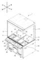
- FIG. 1 is an external view showing the configuration of a prize acquisition game device 1 according to an embodiment of the present invention.
- 1 is a schematic perspective view showing the configuration of a prize acquisition game device 1 according to the present embodiment.
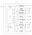
- 1 is a block diagram showing a configuration of a prize acquisition game device 1 according to an embodiment of the present invention.
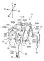
- 2 is a schematic diagram showing the configuration of a prize acquisition unit 20 according to the present embodiment.
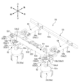
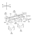
- FIG. 2 is a schematic perspective view showing the configuration of a moving unit 50 according to the present embodiment.
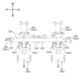
- FIG. FIG. 2 is a planar perspective view showing the configuration of a moving unit 50 according to the present embodiment.
- FIG. 2 is a right side perspective view showing the configuration of a moving unit 50 according to the present embodiment.
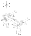
- 13 is a diagram showing a state in which the first right end actuating portion 532 and the second left end actuating portion 533 have been moved to the right.
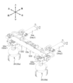
- 13 is a diagram showing a state in which the first right end actuating portion 532 is moved to the left and the second left end actuating portion 533 is moved to the right.
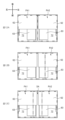
- 12A is a diagram for explaining the setting of the play area.
- Fig. 12A is a diagram showing a state where the first play area PA1 and the second play area PA2 are set to the same size.
- FIG. 12B is a diagram showing a state where the second play area PA2 is set to be smaller than the first play area PA1.
- Fig. 12C is a diagram showing a state where the exhibition area DA is set between the first play area PA1 and the second play area PA2.
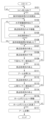
- 4 is a flowchart illustrating an example of the operation of the prize acquisition game device 1 according to the present embodiment.
- 13 is a schematic perspective view showing the configuration of an actuation portion 535 according to the present embodiment.
- a fixed rail extending in the left-right direction across a first play area on the left side and a second play area on the right side that are adjacent to each other in a storage space that contains prizes; a first movable rail supported by the fixed rail in the first play area so as to be movable in a left-right direction perpendicular to the fixed rail; a first prize capture section supported on the first movable rail so as to be movable along a front-rear direction; a first sensor attached to the first moving rail and configured to detect a right end position of the first play area; a first actuator that activates the first sensor, the first actuator being supported by the fixed rail so as to be movable along a left-right direction; a second movable rail supported by the fixed rail in the second play area so as to be movable in a left-right direction perpendicular to the fixed rail; a second prize capture section supported on the second movable rail so
- a service provider e.g., a store clerk, etc.
- the device may also include a control unit that stops the first moving rail at the right end position of the first play area when a first operating unit activates a first sensor by moving the first moving rail along the left-right direction, and stops the second moving rail at the left end position of the second play area when a second operating unit activates a second sensor by moving the second moving rail along the left-right direction.
- the movable range of the first prize acquisition section can be limited in correspondence with the first play area
- the movable range of the second prize acquisition section can be limited in correspondence with the second play area.
- the fixed rail may support the first and second actuators so that they are spaced apart from the right end position of the first play area to the left end position of the second play area, thereby enabling a non-play area to be formed between the first and second play areas.
- the service provider can form not only a play area but also a non-play area within the storage space by adjusting the left-right distance between the first operating unit and the second operating unit.
- the fixed rail supports the first operating portion and the second operating portion so as to be slidable along a left-right direction;
- the first and second operating parts may be positioned on the fixed rail by a magnet at a position after sliding movement.
- the service provider can determine the left-right positions of each of the first and second operating parts with a simple operation.
- a fixed rail extending in the left-right direction across the first play area on the left side and the second play area on the right side, which are adjacent to each other in the storage space for storing prizes; a first movable rail supported by the fixed rail in the first play area so as to be movable in a left-right direction perpendicular to the fixed rail; a first prize capture section supported on the first movable rail so as to be movable along a front-rear direction; a second movable rail supported by the fixed rail in the second play area so as to be movable in a left-right direction perpendicular to the fixed rail; a second prize capture section supported on the second movable rail so as to be movable along a front-rear direction; a first sensor attached to the first moving rail for detecting a boundary position between the first play area and the second play area; a second sensor attached to the second moving rail for detecting a boundary position between the first play area and the second play area; an operating unit that operates the first sensor and the second sensor,
- the present invention is a prize acquisition game device.
- a service provider e.g., a store clerk, etc.
- the device may also include a control unit that stops the first moving rail at the boundary position between the first play area and the second play area when the actuator activates a first sensor by movement of the first moving rail along the left-right direction, and stops the second moving rail at the boundary position between the first play area and the second play area when the actuator activates a second sensor by movement of the second moving rail along the left-right direction.
- the movable range of the first prize acquisition section can be limited in correspondence with the first play area
- the movable range of the second prize acquisition section can be limited in correspondence with the second play area.
- Fig. 1 is an external view showing the configuration of the prize acquisition game device 1 according to this embodiment.
- Fig. 2 is a schematic perspective view showing the configuration of the prize acquisition game device 1 according to this embodiment. Note that Fig. 2 shows a state in which the opening and closing door 11, part of the pillar section 12, the prize acquisition section 20, etc. shown in Fig. 1 have been removed.
- Fig. 3 is a block diagram showing the configuration of the prize acquisition game device 1 according to this embodiment.
- Fig. 4 is a schematic view showing the configuration of the prize acquisition section 20 according to this embodiment. Note that Fig. 4 shows a state in which the design cover of the prize acquisition section 20 has been removed.
- each direction is defined as shown in each figure. That is, the vertical direction is the "up-down direction,” and “up” and “down” are defined according to gravity. Furthermore, based on the view from the player playing the game facing the prize acquisition game device 1, the near side is defined as the “front” and the far side is defined as the “rear,” forming a "front-to-rear direction.” Furthermore, the direction perpendicular to the up-down and front-to-rear directions is defined as the "left-to-right direction,” and “right” and “left” are defined based on the view from the player.
- the prize acquisition game device 1 is used when a player plays a prize acquisition game, and is equipped with a storage section 10 that stores one or more prizes, and a base section 80 provided below the storage section 10.
- the front and left and right sides of the storage unit 10 are made of transparent materials (e.g., transparent resin, glass, etc.) so that players can see the prizes stored within the storage space.
- An opening and closing door 11 is provided on the front of the storage unit 10, allowing a service provider (e.g., a store clerk, etc.) to display and replenish the prizes. Pillars 12 are provided at the four corners of the storage unit 10.
- the storage space enclosed by the storage section 10 is used as a play area where players can play the prize acquisition game. If the pillars 12 on both sides of the opening and closing door 11 are made of mirror-like or transparent materials, they will not stand out visually, making the play area appear larger.
- the storage unit 10 in this embodiment has a prize acquisition unit 20 that performs the operation of acquiring prizes in the storage space, a movement unit 50 that moves the prize acquisition unit 20 in the storage space, and a display unit 60 for displaying the prizes in the storage space.
- a first play area where players play a prize acquisition game is formed on the left side of the storage space
- a second play area is formed on the right side of the storage space.
- a prize acquisition section 20 and an exhibition section 60 are arranged to correspond to the first play area on the left side and the second play area on the right side, respectively. Therefore, within each play area, each prize acquisition section 20 is configured to be able to move and acquire prizes displayed in each exhibition section 60.
- the prize acquisition unit 20 has a first prize acquisition unit 20a corresponding to the first play area on the left side, and a second prize acquisition unit 20b corresponding to the second play area on the right side.
- the range of movement of the first prize acquisition unit 20a within the storage space is limited to within the first play area
- the range of movement of the second prize acquisition unit 20b within the storage space is limited to within the second play area.
- the prize acquisition unit 20 is for acquiring the prizes stored in the storage unit 10 (prizes displayed in the exhibition unit 60) by opening and closing the arms. As shown in FIG. 1, the prize acquisition unit 20 in this embodiment is configured so that it can grasp the prizes with three arms, and is connected to the lower end of the lifting unit 52a.
- the prize acquisition unit 20 has a base unit 21 connected to the lower end of the lift unit 52a, a number of arm units 25 that perform opening and closing operations, and a drive unit 35 that drives the arm units 25 to open and close.
- the base portion 21 has three protruding portions 22 that are offset in three directions at 120 degree intervals from a central axis along the vertical direction.
- the arm portion 25 has an arm 29 that is bent in an L-shape or semicircle, an arm connection portion 28 that detachably connects the arm 29 to the base portion 21, and a claw 30 that is detachably attached to the tip of the arm 29.
- the arm 29 is made up of three arms, a first arm 29A, a second arm 29B, and a third arm 29C, which extend in a three-pronged shape at 120 degree intervals in three directions around the central axis of the base 21 to match the three-pronged shape of the protrusion 22.
- the drive unit 35 is made up of three parts, a first drive unit 35A, a second drive unit 35B, and a third drive unit 35C, which are provided for each arm. As shown in FIG. 4, the first drive unit 35A, the second drive unit 35B, and the third drive unit 35C correspond to the first arm 29A, the second arm 29B, and the third arm 29C, respectively, and drive them to open and close separately.
- the first drive unit 35A has an arm opening/closing motor 35Aa and a gear box 35Ab connected to the arm opening/closing motor 35Aa.
- the gear box 35Ab reduces the rotational force of the arm opening/closing motor 35Aa and outputs it.
- the second drive unit 35B has an arm opening/closing motor 35Ba and a gear box 35Bb connected to the arm opening/closing motor 35Ba
- the third drive unit 35C has an arm opening/closing motor 35Ca and a gear box 35Cb connected to the arm opening/closing motor 35Ca.
- the arm opening/closing motor 35Aa rotates the output shaft in a predetermined direction
- power is transmitted to the first arm 29A via the gear box 35Ab
- the first arm 29A rotates in the closing direction.
- the second arm 29B and the third arm 29C also rotate in the closing direction in the same manner by being driven by the arm opening/closing motor 35Ba and the arm opening/closing motor 35Ca, respectively.
- the moving unit 50 is disposed in the upper part of the storage unit 10 as shown in FIG. 1, and moves the prize acquisition unit 20 within the play area formed by the storage unit 10.
- the moving unit 50 has a horizontal moving unit 51 and a vertical moving unit 52 as shown in FIG. 3.
- the horizontal movement unit 51 moves the prize capture unit 20 horizontally (i.e., forward/backward and left/right) in the play area.
- the vertical movement unit 52 moves the prize capture unit 20 vertically (i.e., up/down) in the play area.
- the display section 60 is for displaying prizes in the storage section 10.
- the display section 60 in this embodiment is for displaying prizes by placing them in the storage space, and as shown in FIG. 2, has a support section 61, a first prize placement section 62 that is placed in the storage space to form an opening area 71, and a second prize placement section 63 that is placed in the storage space to block part of the opening area 71 and form a drop area 72 through which prizes can drop.
- the support section 61 supports the first prize placement section 62 and the second prize placement section 63 so that they can be positioned within the storage space.
- the first prize placement section 62 is fixed and supported so that it cannot be rearranged within the storage space
- the second prize placement section 63 is supported so that it can be rearranged within the storage space.
- the support section 61 in this embodiment supports the second prize placing section 63 in a slidable state below the first prize placing section 62. Therefore, by sliding the second prize placing section 63 in the front-to-rear direction, the position of the second prize placing section 63 relative to the first prize placing section 62 can be changed, and the shape and size of the placement area where prizes can be placed can be changed, or the shape and size of the drop area 72 can be changed.
- the first prize placement section 62 is fixed within the storage space and cannot be repositioned in principle. As shown in FIG. 2, the area within the storage space where the first prize placement section (fixed prize placement section) is not provided (the area that is not blocked off) is the open area 71.
- the second prize placement section 63 is configured to be rearrangeable within the storage space, and as shown in FIG. 2, is supported by the support section 61 so as to block part of the opening area 71, thereby forming a drop area 72.
- the prize that is captured and dropped by the prize capture unit 20 passes (drops) through the drop hole area 72 of the display unit 60, it moves from the play area to the base unit 80.
- the prize that drops from the drop hole area 72 of the display unit 60 is detected by an optical sensor and then guided along a guide path to the prize outlet 96.
- the optical sensor detects the presence or absence of a prize using a light-emitting element and a light-receiving element that are attached along the guide path.
- the base 80 is the base of the housing located below the storage unit 10, and holds the storage unit 10 at a high position so that the player can play the game while standing and facing forward.
- the base unit 80 in this embodiment has an operation unit 90, a play fee detection unit 93, a prize outlet 96, a setting unit 100, a control unit 110, and a memory unit 120.
- the operation unit 90 allows the player to operate the game. As shown in Figures 1 to 3, the operation unit 90 in this embodiment has at least a joystick 91 and an operation button 92.
- the joystick 91 is an operating lever that the player uses to move the prize capture unit 20 horizontally.
- the operation button 92 is an operating button that the player uses to determine the position of the prize capture unit 20 in the horizontal direction. When the player presses the operation button 92, the prize capture unit 20 begins to descend at the determined position.
- the play fee detection unit 93 is for detecting the payment of a play fee by a player.
- the play fee detection unit 93 has a coin insertion slot 94, a coin detection sensor (not shown), a coin passage path (not shown), and a coin box (not shown).
- the prize acquisition game begins when the player inserts a predetermined number of coins into the coin insertion slot 94.
- the coins inserted into the coin insertion slot 94 are detected by a coin detection sensor.
- the coin detection sensor is, for example, an optical sensor, and detects the presence or absence of a coin inserted through the coin slot 94 using a light-emitting element and a light-receiving element attached to the coin currency path. Coins that pass through the coin currency path in this way are stored in the coin box.
- the prize outlet 96 is provided on the front of the base 80 and is used to remove a prize acquired by the prize acquisition section 20 when the prize falls from the drop area 72 in the display section 60.
- the setting unit 100 is used when a player performs game operations or when a service provider performs setting operations. As shown in Figures 1 to 3, the setting unit 100 in this embodiment has a setting operation unit 101 and a display unit 102.
- the setting operation unit 101 is for accepting operation input.
- the setting operation unit 101 is configured as a touch panel, and accepts input instructions from the operator from the position where the operator presses the touch panel.
- the touch panel is layered on top of the display unit 102, and when a touch operation is performed on the screen, the pressed position (contact position) can be detected based on the change in capacitance between the fingertip and the conductive film.
- the display unit 102 displays various screens such as a game screen and a setting screen.
- the display unit 102 is configured as a liquid crystal display.
- the control unit 110 is provided inside the base unit 80 and is a control unit for performing various controls of the prize acquisition game device 1. As shown in FIG. 3, the control unit 110 has at least a CPU 111 and a memory 112.
- the CPU 111 is an arithmetic processing unit that controls the entire game device.
- the memory 112 is used to secure an area for storing programs for the CPU 111, a working area, etc., and has memory elements such as RAM.
- the memory unit 120 is a unit that stores programs and data for the control unit 110 to execute game processing. In this embodiment, it has a memory element such as a ROM that is a read-only memory area.
- Fig. 5 is a schematic perspective view showing the configuration of the moving section 50 according to this embodiment.
- Fig. 6 is a planar perspective view showing the configuration of the moving section 50 according to this embodiment.
- Fig. 7 is a right side perspective view showing the configuration of the moving section 50 according to this embodiment.
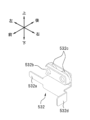
- Fig. 8 is a schematic perspective view showing the configuration of the first right end actuating section 532 according to this embodiment.
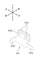
- Fig. 9 is a schematic perspective view showing the configuration of the second left end actuating section 533 according to this embodiment.
- the horizontal movement unit 51 has a left-right movement unit 53 and a front-back movement unit 54.
- the left-right movement unit 53 moves the prize capture unit 20 left-right in the play area.
- the front-back movement unit 54 moves the prize capture unit 20 forward and backward in the play area.
- the left-right movement unit 53 in this embodiment has a pair of fixed rails 53a that extend in the left-right direction within the storage space, and left-right movement motors 53b that are located on both the left and right ends of the front fixed rail 53a.
- the forward/backward movement unit 54 in this embodiment has multiple movement rails 54a that extend in the forward/backward direction within the storage space, and forward/backward movement motors 54b that are located at the front ends of each of the movement rails 54a.
- the vertical movement unit 52 has a lifting unit 52a that is configured to be freely expandable and contractable in the vertical direction, and a hanging unit 52b that suspends the lifting unit 52a so that it can be raised and lowered.
- the lifting unit 52a is configured by fitting a number of pipes of successively smaller diameters into each other in a nested manner so that they can slide freely.
- the prize capture unit 20 is attached to the lower end of the lifting unit 52a while connected to a wire that passes through the inside of the pipe.
- the lifting unit 52a is attached to the lower end of the hanging unit 52b with the prize capture unit 20 suspended from it.
- the upper end of the hanging unit 52b is supported by a moving rail 54a so that it can be freely moved in the front-to-rear direction.
- the vertical movement unit 52 in this embodiment has a wire winding unit, a motor for vertical movement, an upper limit sensor, and a lower limit sensor inside the hanging unit 52b.
- the wire winding unit is driven by the motor for vertical movement to wind up the wire, thereby raising the prize capture unit 20 while sequentially storing the lower pipes in the upper pipe, or to lower the prize capture unit 20 while sequentially sending out the lower pipes from the upper pipe by unwinding the wire.
- the upper limit sensor detects whether the prize capture unit 20 has stopped rising by winding up the wire connected to the prize capture unit 20.
- the lower limit sensor detects whether the prize capture unit 20 has stopped descending based on a change in tension of the wire connected to the prize capture unit 20.
- the fixed rail 53a in this embodiment extends in the left-right direction across the first play area on the left side and the second play area on the right side, which are adjacent to each other on the left side within the storage space, and as shown in Figure 5, it supports a first movable rail 54a1 corresponding to the first play area on the left side and a second movable rail 54a2 corresponding to the second play area on the right side so that they can move freely along a shared rail.
- a first left-right movement motor 53b1 for moving the first moving rail 54a1 in the left-right direction is disposed at the left end of the front fixed rail 53a. Furthermore, a second left-right movement motor 53b2 for moving the second moving rail 54a2 in the left-right direction is disposed at the right end of the front fixed rail 53a.
- the front fixed rail 53a has a U-shaped cross section, and inside it are a first driving pulley that is rotated by a first left-right movement motor 53b1, a first driven pulley attached to the right end of the front fixed rail 53a, and a first left-right belt that is stretched between the first driving pulley and the first driven pulley.
- a second driving pulley that is driven to rotate by a second left/right movement motor 53b2, a second driven pulley attached to the left end of the front fixed rail 53a, and a second left/right belt that is stretched between the second driving pulley and the second driven pulley.
- the first left-right belt and the second left-right belt are arranged parallel to each other inside the front fixed rail 53a, and the first moving rail 54a1 is connected to the first left-right belt via the first connecting part, and the second moving rail 54a2 is connected to the 21st left-right belt via the second connecting part.
- the first left-right movement motor 53b1 rotates forward or backward
- the first moving rail 54a1 connected to the first left-right belt can move back and forth in the left-right direction along the fixed rail 53a.
- the second left-right movement motor 53b2 rotates forward or backward
- the second moving rail 54a2 connected to the second left-right belt can move back and forth in the left-right direction along the fixed rail 53a.
- the first movable rail 54a1 supports a first hanging portion 52b1 from which a first prize acquisition portion 20a corresponding to the first play area on the left side is suspended so as to be movable in the front-rear direction.
- the first prize acquisition portion 20a is supported by the first movable rail 54a1 so as to be movable in the front-rear direction.
- the second movable rail 54a2 supports a second hanging portion 52b2 from which a second prize acquisition portion 20b corresponding to the second play area on the right side is suspended so as to be movable in the front-rear direction.
- the second prize acquisition portion 20b is supported by the second movable rail 54a2 so as to be movable in the front-rear direction.
- a first forward/backward movement motor 54b1 is disposed at the front end of the first moving rail 54a1 to move the first hanging part 52b1, from which the first prize capture part 20a is suspended, in the forward/backward direction.
- a second forward/backward movement motor 54b2 is disposed at the front end of the second moving rail 54a2 to move the second hanging part 52b2, from which the second prize capture part 20b is suspended, in the forward/backward direction.
- the first moving rail 54a1 has a U-shaped cross section, and inside it are arranged a driven pulley that is rotated by a first forward/backward movement motor 54b1, a driven pulley attached to the rear end of the first moving rail 54a1, and a forward/backward belt that is stretched between the driven pulley and the driven pulley.
- the first hanging part 52b1 is connected to the forward/backward belt via a connecting part.
- the first prize capture section 20a can move back and forth in the forward/backward direction along the first moving rail 54a1 together with the first hanging section 52b1 connected to the forward/backward belt.
- the second moving rail 54a2 there are arranged a driven pulley that is rotated by a second forward/backward movement motor 54b2, a driven pulley that is disposed at the rear end of the second moving rail 54a2, and a forward/backward belt that is stretched between the driven pulley and the driven pulley.
- the second hanging part 52b2 is connected to the forward/backward belt via a connecting part.
- the second prize capture section 20b can move back and forth in the forward/backward direction along the second moving rail 54a2 together with the second hanging section 52b2 connected to the forward/backward belt.
- a first left edge sensor 54c1 that detects the left edge position of the first play area is attached to the front left side of the first moving rail 54a1.
- a first left edge actuator 531 that activates the first left edge sensor 54c1 is attached to the left end of the front fixed rail 53a.
- the first prize capture unit 20a together with the first moving rail 54a1 are restricted from moving leftward in the left-right direction in the first play area.
- a first right edge sensor 54c2 that detects the right edge position of the first play area is attached to the front right side of the first moving rail 54a1.
- a first right edge actuator 532 that activates the first right edge sensor 54c2 is supported in the center of the front fixed rail 53a.
- the first prize capture unit 20a together with the first moving rail 54a1 are restricted from moving to the right in the left-right direction in the first play area.
- a second left edge sensor 54c3 that detects the left edge position of the second play area is attached to the front left side of the second moving rail 54a2.
- a second left edge actuator 533 that activates the second left edge sensor 54c3 is supported in the center of the front fixed rail 53a.
- a second right end sensor 54c4 that detects the right end position of the second play area is attached to the front right side of the second moving rail 54a2.
- a second right end actuator 534 that activates the second right end sensor 54c4 is attached to the right end of the front fixed rail 53a.
- the second prize capture unit 20b together with the second moving rail 54a2 are restricted from moving to the right in the left-right direction in the second play area.
- the first left end sensor 54c1, the first right end sensor 54c2, the second left end sensor 54c3, and the second right end sensor 54c4 are optical sensors that detect the presence or absence of an obstructing object depending on whether the light receiving unit receives the light irradiated from the light emitting unit. In other words, each sensor can detect this when the operating unit reaches between the light emitting unit and the light receiving unit.
- the first left end actuating unit 531 and the second right end actuating unit 534 are fixed to the front fixed rail 53a so that their mounting positions cannot be changed in principle.
- the first right end actuating unit 532 and the second left end actuating unit 533 are supported by the front fixed rail 53a so that they can move freely in the left-right direction, so that their mounting positions can be changed (i.e., the right end position of the first play area and the left end position of the second play area can each be changed).
- the first right end operating part 532 is an example of a first operating part, and is a member that can slide along the front fixed rail 53a. As shown in FIG. 8, the first right end operating part 532 in this embodiment has a shielding part 532a that protrudes to the left in the left-right direction and blocks light emitted from the first right end sensor 54c2 (first sensor), a magnet 532b, two wheels 532c, and a knob part 532d that protrudes to the front in the front-rear direction.
- a concave groove extending in the left-right direction is formed on the inner side of the front fixed rail 53a.
- the front fixed rail 53a supports the first right end actuator 532 so that the wheels can be placed on the groove to guide the first right end actuator 532.
- a service provider e.g., a store clerk, etc.
- the first right end actuator 532 can be fixed in the position determined after the sliding movement by the magnet 532b (the position of the first right end actuator 532 after the sliding movement can be maintained).
- the second left end operating part 533 is an example of a second operating part, and is a member that can slide along the front fixed rail 53a. As shown in FIG. 9, the second left end operating part 533 in this embodiment has a shielding part 533a that protrudes to the right in the left-right direction and blocks light emitted from the second left end sensor 54c3 (second sensor), a magnet 533b, two wheels 533c, and a knob part 533d that protrudes to the front in the front-rear direction.
- the second left end actuating unit 533 is guided by placing its wheels in the grooves of the front fixed rail 53a.
- the service provider can operate knob 533d independently of knob 532d of the first right end actuating unit 532 to slide the first right end actuating unit 532 left and right along the front fixed rail 53a, changing the position of the second left end actuating unit 533 and adjusting the left end position of the second play area.
- the second left end actuating unit 533 can be fixed in the position determined after the sliding movement by the magnet 533b (the position of the second left end actuating unit 533 after the sliding movement can be maintained).
- the front fixed rail 53a supports the first right end actuator 532 at a position after sliding movement between the first moving rail 54a1 and the second left end actuator 533, thereby making it possible to change the right end position of the first play area, and supports the second left end actuator 533 at a position after sliding movement between the first right end actuator 532 and the second moving rail 54a2, thereby making it possible to change the left end position of the second play area.
- a first front end sensor 52d1 that detects the front end position of the first play area is attached to the front end of the first hanging part 52b1.
- a first front end actuating part 541 that actuates the first front end sensor 52d1 is attached to the front end of the first moving rail 54a1.
- the first prize capture unit 20a together with the first hanging part 52b1 are restricted from moving forward in the front-to-rear direction in the first play area.
- a second front end sensor 52d3 that detects the front end position of the second play area is attached to the front end of the second hanging part 52b2.
- a second front end actuating part 543 that actuates the second front end sensor 52d3 is attached to the front end of the second moving rail 54a2.
- a first rear end sensor (not shown) that detects the rear end position of the first play area is attached to the rear end of the first hanging part 52b1. And, as shown in FIG. 5, a first rear end actuating part 542 that activates the first rear end sensor is attached to the rear end of the first moving rail 54a1.
- the first prize capture unit 20a together with the first hanging part 52b1 are restricted from moving rearward in the fore-and-aft direction in the first play area.
- a second rear end sensor (not shown) that detects the rear end position of the second play area is attached to the rear end of the second hanging part 52b2. And, as shown in Figures 5 and 7, a second rear end actuating part 544 that activates the second rear end sensor is attached to the rear end of the second moving rail 54a2.
- the second prize capture section 20b together with the second hanging section 52b2 is restricted from moving rearward in the fore-and-aft direction in the second play area.
- the first front end sensor 52d1, the first rear end sensor, the second front end sensor 52d3, and the second rear end sensor are optical sensors that detect the presence or absence of an obstructing object based on whether the light-receiving unit receives the light irradiated from the light-emitting unit. In other words, each sensor can detect this when the operating unit reaches between the light-emitting unit and the light-receiving unit.
- the first front end actuating part 541 and the first rear end actuating part 542 are fixed to the first moving rail 54a1, and in principle their mounting positions cannot be changed.
- the second front end actuating part 543 and the second rear end actuating part 544 are fixed to the second moving rail 54a2, and in principle their mounting positions cannot be changed.
- Fig. 10 is a diagram showing a state in which the first right end actuation unit 532 and the second left end actuation unit 533 are moved to the right side.
- Fig. 11 is a diagram showing a state in which the first right end actuation unit 532 is moved to the left side and the second left end actuation unit 533 is moved to the right side.
- Fig. 12 is a diagram explaining the setting of the play area.
- Fig. 12A is a diagram showing a state in which the first play area PA1 and the second play area PA2 are set to the same size.
- FIG. 12B is a diagram showing a state in which the second play area PA2, which is smaller than the first play area PA1, is set.
- Fig. 12C is a diagram showing a state in which the exhibition area DA is set between the first play area PA1 and the second play area PA2. In the figures, each area is illustrated using a two-dot chain line.
- the right end position of the first play area and the left end position of the second play area will be set to the left-right center of the fixed rail 53a.
- the first play area PA1 and the second play area PA2 will be the same size. Therefore, the range of movement within the storage space of the first prize acquisition unit 20a and the second prize acquisition unit 20b will also be the same size.
- the right end position of the first play area and the left end position of the second play area will be changed to a position slid from the center of the left-right direction of the fixed rail 53a to the right.
- the first play area PA1 will be larger than the second play area PA2. Therefore, compared to the state shown in FIG. 5, the movable range of the first prize acquisition unit 20a within the storage space will be expanded, while the movable range of the second prize acquisition unit 20b within the storage space will be reduced.
- the right end position of the first play area is changed to a position slid leftward from the center of the left-right direction of the fixed rail 53a
- the left end position of the second play area is changed to a position slid rightward from the center of the left-right direction of the fixed rail 53a.
- a non-play area DA is formed between the first play area PA1 and the second play area PA2 as shown in Fig. 12C. Therefore, compared to the state shown in FIG. 5, the range of movement within the storage space of the first prize capture unit 20a and the second prize capture unit 20b is reduced, but it is possible to place prizes and decorations for display in the non-play area DA, and to set up displays (small monitors) for advertising, game explanations, etc.
- Fig. 13 is a flow chart for explaining an example of the operation of the prize acquisition game device 1 according to this embodiment. Below, an example of the operation in the first play area will be specifically described, and the second play area will not be described since it is similar to the first play area.
- step S101 When the play fee detection unit 93 detects the insertion of a coin (step S101: YES), the control unit 110 starts timing the preset operation time limit (step S102).
- control unit 110 when the control unit 110 receives an operation signal for moving the first prize acquisition unit 20a horizontally as a result of the player operating the joystick 91 (step S103: YES), it drives the horizontal movement unit 51 in accordance with the player's operation to move the first prize acquisition unit 20a horizontally in the first play area (step S104).
- the control unit 110 stops the first prize capturing unit 20a at the right end position of the first play area. Also, if the first rear end operating unit 542 activates the first rear end sensor due to the rearward movement of the first hanging part 52b1, the control unit 110 stops the first prize capturing unit 20a at the rear end position of the first play area.
- the control unit 110 stops the first prize capturing unit 20a at the left end position of the first play area. Furthermore, when the first front end actuation unit 541 activates the first front end sensor 52d1 due to the forward movement of the first hanging unit 52b1, the first prize capture unit 20a is stopped at the front end position of the first play area.
- step S106 determines whether the operation time limit has elapsed. If the operation time limit has not elapsed (step S106: NO), the control unit 110 returns to the process of step S103. If the operation time limit has elapsed (step S106: YES), the first prize acquisition unit 20a is stopped (step S107).
- control unit 110 receives an operation signal for determining the position of the first prize acquisition unit 20a after horizontal movement by the player operating the operation button 92 (step S105: YES), it stops the first prize acquisition unit 20a at the position after the horizontal movement (step S107).
- step S106 determines whether or not the operation time limit has elapsed. If the operation time limit has not elapsed (step S106: NO), the control unit 110 returns to the process of step S103. If the operation time limit has elapsed (step S106: YES), the first prize acquisition unit 20a is stopped (step S107).
- control unit 110 drives the vertical movement unit 52 to lower the first prize capture unit 20a to the stopping position in the first play area (step S108).
- step S109 When the lower limit sensor detects that the descent of the first prize capture unit 20a has stopped (step S109: YES), the control unit 110 stops the first prize capture unit 20a (step S110).
- step S110 when the first prize acquisition unit 20a is in a stopped state (step S110), the control unit 110 causes the drive unit 35 to rotate the arm unit 25 in a closing direction (step S111).
- step S111 when the arm portion 25 of the first prize capturing portion 20a is in a closed state (step S111), the control portion 110 drives the vertical movement portion 52 to raise the first prize capturing portion 20a (step S112).
- step S113 When the upper limit sensor detects that the first prize acquisition unit 20a has stopped rising (step S113: YES), the control unit 110 stops the first prize acquisition unit 20a (step S114).
- control unit 110 drives the horizontal movement unit 51 to move the first prize acquisition unit 20a toward the home position (step S115), and determines whether the home position has been reached (step S116).
- control unit 110 determines that the first prize capture unit 20a has reached the home position when the first left end actuation unit 531 actuates the first left end sensor 54c1 as the first moving rail 54a1 moves leftward, and the first front end actuation unit 541 actuates the first front end sensor 52d1 as the first hanging unit 52b1 moves forward.
- step S116 when the first prize acquisition unit 20a is located at the home position (step S116: YES), the control unit 110 causes the drive unit 35 to rotate the arm unit 25 in the opening direction (step S117).
- the service provider can change the size of the first play area and the second play area individually by adjusting the left-right position of the first right end operating unit 532 (first operating unit) and the second left end operating unit 533 (second operating unit) along the fixed rail 53a. Then, in the first play area and the second play area whose size has been changed, it becomes possible to limit the range of movement within the storage space of each of the first prize acquisition unit 20a and the second prize acquisition unit 20b.
- an invention may be constructed by deleting some invention-specific matters from all of the invention-specific matters disclosed in the above embodiments, or an invention may be constructed by appropriately combining all of the invention-specific matters disclosed in the above embodiments with the invention-specific matters disclosed in the embodiments described below.
- the prizes stored in the storage section 10 are not limited to items that the player can directly acquire (e.g., stuffed toys, etc.), but also include items that are stored as targets for acquisition in the game and can be exchanged for other prizes after acquisition, and items that are not provided themselves but are used to compete for points or rankings.
- the prize capturing unit 20 having three arm units 25 has been described as an example, but the present invention is not limited to this.
- the present invention can be applied to a prize capturing unit 20 having two or less arm units 25, or a prize capturing unit 20 having four or more arm units 25.
- the integrated operating unit 535 is supported by the fixed rail 53a so as to be able to slide between the first moving rail 54a1 and the second moving rail 54a2.
- the first right end sensor 54c2 (first sensor) and the second left end sensor 54c3 (second sensor) function as sensors that detect the boundary position between the first play area and the second play area. Therefore, the service provider can simultaneously change the size of the first play area and the second play area by adjusting the left-right position of the integrated operating unit along the fixed rail 53a.
- first right end operating part 532 (first operating part) and the second left end operating part 533 (second operating part) each have two wheels, but the present invention is not limited to this.
- first right end operating part 532 (first operating part) and the second left end operating part 533 (second operating part), which do not have wheels may each be structured to be slidably fitted into a groove on the inside of the front fixed rail 53a.
- first right end sensor 54c2 first sensor
- second left end sensor 54c3 second sensor
- a first right end operating part 532 (first operating part) is attached to the front right side of the first moving rail 54a1 in place of the first right end sensor 54c2
- a second left end operating part 533 (second operating part) is attached to the front left side of the second moving rail 54a2 in place of the second left end sensor 54c3.
- This allows the service provider to change the sizes of the first play area and the second play area individually by adjusting the left-right positions of the first right end sensor 54c2 (first sensor) and the second left end sensor 54c3 (second sensor) along the fixed rail 53a.
- the first right-end sensor 54c2 (first sensor) and the second left-end sensor 54c3 (second sensor) may be integrated.
- each of the first front end actuating portion 541 and the first rear end actuating portion 542 change its position in the front-rear direction along the first moving rail 54a1.
- each of the second front end actuating portion 543 and the second rear end actuating portion 544 change its position in the front-rear direction along the second moving rail 54a2.
- a plurality of screw holes are formed at equal intervals along the front-rear direction in each of the first moving rail 54a1 and the second moving rail 54a2, and the front end actuating part and the rear end actuating part are attached at the changed positions. Make it possible.
Landscapes
- Physics & Mathematics (AREA)
- General Physics & Mathematics (AREA)
- Engineering & Computer Science (AREA)
- Computer Networks & Wireless Communication (AREA)
- Multimedia (AREA)
- Pinball Game Machines (AREA)
Priority Applications (3)
| Application Number | Priority Date | Filing Date | Title |
|---|---|---|---|
| EP23921309.3A EP4663261A1 (en) | 2023-02-06 | 2023-11-17 | Prize-acquisition game device |
| CN202380093347.2A CN120641186A (zh) | 2023-02-06 | 2023-11-17 | 奖品获取游戏设备 |
| US19/292,021 US20250356736A1 (en) | 2023-02-06 | 2025-08-06 | Prize-acquisition game device |
Applications Claiming Priority (2)
| Application Number | Priority Date | Filing Date | Title |
|---|---|---|---|
| JP2023016481A JP2024111774A (ja) | 2023-02-06 | 2023-02-06 | 景品取得ゲーム装置 |
| JP2023-016481 | 2023-08-10 |
Related Child Applications (1)
| Application Number | Title | Priority Date | Filing Date |
|---|---|---|---|
| US19/292,021 Continuation US20250356736A1 (en) | 2023-02-06 | 2025-08-06 | Prize-acquisition game device |
Publications (1)
| Publication Number | Publication Date |
|---|---|
| WO2024166488A1 true WO2024166488A1 (ja) | 2024-08-15 |
Family
ID=92262959
Family Applications (1)
| Application Number | Title | Priority Date | Filing Date |
|---|---|---|---|
| PCT/JP2023/041539 Ceased WO2024166488A1 (ja) | 2023-02-06 | 2023-11-17 | 景品取得ゲーム装置 |
Country Status (5)
| Country | Link |
|---|---|
| US (1) | US20250356736A1 (cg-RX-API-DMAC10.html) |
| EP (1) | EP4663261A1 (cg-RX-API-DMAC10.html) |
| JP (2) | JP2024111774A (cg-RX-API-DMAC10.html) |
| CN (1) | CN120641186A (cg-RX-API-DMAC10.html) |
| WO (1) | WO2024166488A1 (cg-RX-API-DMAC10.html) |
Cited By (1)
| Publication number | Priority date | Publication date | Assignee | Title |
|---|---|---|---|---|
| US20250090942A1 (en) * | 2023-09-18 | 2025-03-20 | Paokai Electronic Enterprise Co., Ltd. | Multi-claw game machine |
Families Citing this family (1)
| Publication number | Priority date | Publication date | Assignee | Title |
|---|---|---|---|---|
| US20250144509A1 (en) * | 2023-09-15 | 2025-05-08 | Aries Technology, Llc | Method and system for detecting prize collection in skill-type prize collection devices |
Citations (7)
| Publication number | Priority date | Publication date | Assignee | Title |
|---|---|---|---|---|
| JPS52108226A (en) * | 1976-03-06 | 1977-09-10 | Ushio Sangiyou Kk | Crane game device |
| JPH11239669A (ja) * | 1997-12-01 | 1999-09-07 | Sega Enterp Ltd | 景品取得ゲーム装置 |
| JP2002239208A (ja) * | 2001-02-20 | 2002-08-27 | Aruze Corp | クレーンゲーム機 |
| JP2006122510A (ja) * | 2004-10-29 | 2006-05-18 | Sega Corp | 景品取得ゲーム装置 |
| JP2012254223A (ja) * | 2011-06-09 | 2012-12-27 | Sega Corp | 景品取得ゲーム機 |
| JP2013090863A (ja) * | 2011-10-27 | 2013-05-16 | Toso Co Ltd | カーテンの一時保持装置 |
| JP2019098076A (ja) | 2017-12-07 | 2019-06-24 | 株式会社セガゲームス | 景品取得ゲーム装置 |
-
2023
- 2023-02-06 JP JP2023016481A patent/JP2024111774A/ja active Pending
- 2023-11-17 EP EP23921309.3A patent/EP4663261A1/en active Pending
- 2023-11-17 WO PCT/JP2023/041539 patent/WO2024166488A1/ja not_active Ceased
- 2023-11-17 CN CN202380093347.2A patent/CN120641186A/zh active Pending
-
2025
- 2025-08-05 JP JP2025130568A patent/JP2025160470A/ja active Pending
- 2025-08-06 US US19/292,021 patent/US20250356736A1/en active Pending
Patent Citations (7)
| Publication number | Priority date | Publication date | Assignee | Title |
|---|---|---|---|---|
| JPS52108226A (en) * | 1976-03-06 | 1977-09-10 | Ushio Sangiyou Kk | Crane game device |
| JPH11239669A (ja) * | 1997-12-01 | 1999-09-07 | Sega Enterp Ltd | 景品取得ゲーム装置 |
| JP2002239208A (ja) * | 2001-02-20 | 2002-08-27 | Aruze Corp | クレーンゲーム機 |
| JP2006122510A (ja) * | 2004-10-29 | 2006-05-18 | Sega Corp | 景品取得ゲーム装置 |
| JP2012254223A (ja) * | 2011-06-09 | 2012-12-27 | Sega Corp | 景品取得ゲーム機 |
| JP2013090863A (ja) * | 2011-10-27 | 2013-05-16 | Toso Co Ltd | カーテンの一時保持装置 |
| JP2019098076A (ja) | 2017-12-07 | 2019-06-24 | 株式会社セガゲームス | 景品取得ゲーム装置 |
Non-Patent Citations (1)
| Title |
|---|
| See also references of EP4663261A1 |
Cited By (1)
| Publication number | Priority date | Publication date | Assignee | Title |
|---|---|---|---|---|
| US20250090942A1 (en) * | 2023-09-18 | 2025-03-20 | Paokai Electronic Enterprise Co., Ltd. | Multi-claw game machine |
Also Published As
| Publication number | Publication date |
|---|---|
| JP2025160470A (ja) | 2025-10-22 |
| EP4663261A1 (en) | 2025-12-17 |
| JP2024111774A (ja) | 2024-08-19 |
| CN120641186A (zh) | 2025-09-12 |
| US20250356736A1 (en) | 2025-11-20 |
Similar Documents
| Publication | Publication Date | Title |
|---|---|---|
| JP2025160470A (ja) | 景品取得ゲーム装置 | |
| JP7298793B1 (ja) | 景品取得ゲーム装置 | |
| WO2010095633A1 (ja) | 景品獲得ゲーム装置 | |
| JP7075576B2 (ja) | 景品取得ゲーム装置 | |
| WO2010095632A1 (ja) | 景品獲得ゲーム装置用の景品載置部及び景品獲得ゲーム装置 | |
| JP6544024B2 (ja) | 景品取得ゲーム装置 | |
| WO2025094741A1 (ja) | 景品取得ゲーム装置 | |
| JP2025029554A (ja) | 景品取得ゲーム装置、及び景品取得ゲーム装置のアーム調節方法 | |
| US20250262525A1 (en) | Prize acquisition game device and crane | |
| JP5379513B2 (ja) | 景品獲得ゲーム装置 | |
| WO2025069548A1 (ja) | 景品取得ゲーム装置 | |
| KR20150001545U (ko) | 경품 게임 장치 | |
| JP2009000381A (ja) | 遊技機 | |
| JP2026010889A (ja) | 景品取得ゲーム装置 | |
| JP7715264B1 (ja) | 景品取得ゲーム装置 | |
| JP6665631B2 (ja) | 景品取得ゲーム装置 | |
| JP2025166394A (ja) | 景品取得ゲーム装置 | |
| JP2010188012A (ja) | 景品獲得ゲーム装置 | |
| JP2010104478A (ja) | 遊技機 | |
| JP6740673B2 (ja) | 景品取得ゲーム装置 | |
| JP6978725B2 (ja) | 景品取得ゲーム装置 | |
| JP2025171152A (ja) | 景品取得ゲーム装置 | |
| JP2024084108A (ja) | 景品取得ゲーム装置及び景品取得ユニット | |
| JP2005125007A (ja) | 遊技機 | |
| JP2002177437A (ja) | 遊技機 |
Legal Events
| Date | Code | Title | Description |
|---|---|---|---|
| 121 | Ep: the epo has been informed by wipo that ep was designated in this application |
Ref document number: 23921309 Country of ref document: EP Kind code of ref document: A1 |
|
| WWE | Wipo information: entry into national phase |
Ref document number: 202380093347.2 Country of ref document: CN |
|
| NENP | Non-entry into the national phase |
Ref country code: DE |
|
| WWP | Wipo information: published in national office |
Ref document number: 202380093347.2 Country of ref document: CN |
|
| WWP | Wipo information: published in national office |
Ref document number: 2023921309 Country of ref document: EP |