WO2024166293A1 - 制御装置、ロボットシステム、ロボットの制御方法 - Google Patents
制御装置、ロボットシステム、ロボットの制御方法 Download PDFInfo
- Publication number
- WO2024166293A1 WO2024166293A1 PCT/JP2023/004366 JP2023004366W WO2024166293A1 WO 2024166293 A1 WO2024166293 A1 WO 2024166293A1 JP 2023004366 W JP2023004366 W JP 2023004366W WO 2024166293 A1 WO2024166293 A1 WO 2024166293A1
- Authority
- WO
- WIPO (PCT)
- Prior art keywords
- robot arm
- robot
- suction device
- workpiece
- suction
- Prior art date
- Legal status (The legal status is an assumption and is not a legal conclusion. Google has not performed a legal analysis and makes no representation as to the accuracy of the status listed.)
- Ceased
Links
Images



Classifications
-
- B—PERFORMING OPERATIONS; TRANSPORTING
- B25—HAND TOOLS; PORTABLE POWER-DRIVEN TOOLS; MANIPULATORS
- B25J—MANIPULATORS; CHAMBERS PROVIDED WITH MANIPULATION DEVICES
- B25J13/00—Controls for manipulators
- B25J13/08—Controls for manipulators by means of sensing devices, e.g. viewing or touching devices
Definitions
- the technology disclosed herein relates to a control device, a robot system, and a method for controlling a robot.
- Robots that pick up a workpiece using a hand attached to a robot arm have been known for some time.
- the robot system disclosed in Patent Document 1 controls a manipulator, i.e., a robot arm, to have a gripping device 3, i.e., a hand, hold a workpiece. If the hand fails to hold the workpiece, the robot system changes the holding position and has the hand try to pick up the workpiece again.
- the technology disclosed here was developed in light of this issue, and its purpose is to reduce the time required to retry a picking operation.
- the control device disclosed herein is a control device that controls a robot having a robot arm and a hand attached to the robot arm, including a suction device whose position relative to the robot arm can be changed, and is equipped with an operation controller that causes the robot to execute a picking operation in which the suction device moves to a workpiece and adsorbs the workpiece to the suction device, and a determiner that determines whether the suction device has successfully adsorbed the workpiece, and when the determiner determines that the picking operation has failed, the operation controller changes the position of the suction device relative to the robot arm and causes the robot to re-execute the picking operation without changing the path of the robot arm.
- the robot system disclosed herein includes a robot having a robot arm and a hand attached to the robot arm, and a control device that controls the robot, and the hand includes a suction device whose position relative to the robot arm can be changed.
- the control device has an operation controller that causes the robot to execute a picking operation in which the suction device moves to a workpiece and the workpiece is sucked up by the suction device, and a judger that judges whether the suction device has succeeded in sucking up the workpiece. If the judger determines that the picking operation has failed, the operation controller changes the position of the suction device relative to the robot arm and causes the robot to re-execute the picking operation without changing the path of the robot arm.
- the robot control method disclosed herein includes having a robot arm and a hand attached to the robot arm, the robot arm including a suction device whose position relative to the robot arm can be changed, execute a picking operation in which the suction device moves to a workpiece and adsorbs the workpiece to the suction device, determine whether the suction device has successfully adsorbed the workpiece, and, if the suction has failed, change the position of the suction device relative to the robot arm and have the robot re-execute the picking operation without changing the path of the robot arm.
- the control device can reduce the time required to retry a picking operation.
- the robot system described above can reduce the time required to retry a picking operation.
- the robot control method described above can reduce the time required to retry a picking operation.
- FIG. 1 is a schematic diagram showing the configuration of a robot system.
- FIG. 2 is a diagram showing a schematic hardware configuration of the robot control device and the main control device.
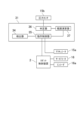
- FIG. 3 is a block diagram showing the configuration of a control system of the controller.
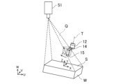
- FIG. 4 is an explanatory diagram for explaining the range in which the relative positions of the suction units can be changed.
- FIG. 5 is an explanatory diagram showing the camera position and the hand center position on the XY plane of the work coordinate system.
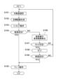
- FIG. 6 is a flow chart of the pick and place process.
- Figure 1 is a schematic diagram showing the configuration of a robot system 100.
- the robot system 100 includes a robot 1 and a main control device 3 that controls the robot 1.
- the main control device 3 controls the robot 1 to cause the robot 1 to execute a process.
- the process performed by the robot 1 is a pick-and-place process.
- the robot 1 picks up a target workpiece from a first container 91 in which multiple workpieces are piled up randomly, and transfers it into a second container 92.
- the robot 1 arranges the target workpieces in a regular pattern in the second container 92.
- the robot system 100 arranges the multiple workpieces in the first container 91 into the second container 92 by repeating the pick-and-place process.
- the robot system 100 may include a camera 51 that captures an image of the workpiece.
- the camera 51 is fixedly disposed above the first container 91.
- the camera 51 captures an image of the inside of the first container 91 from above.
- the camera 51 captures an image including a plurality of workpieces in the first container 91.
- the image is a two-dimensional image or a three-dimensional image.
- the three-dimensional image may be point cloud data, an RGB-D image, an RGB image, a depth image, a voxel, or the like.
- the camera 51 may be a three-dimensional camera, i.e., an RGB-D camera that outputs an RGB-D image, a stereo camera that captures an RGB image, or a three-dimensional vision sensor that captures point cloud data.
- the camera 51 may also capture an image of the first container 91.
- the camera 51 may also capture an image of the inside of the second container 92.
- the robot 1 has a robot arm 12 and a hand 14 attached to the robot arm 12.
- the robot 1 is an industrial robot.
- the hand 14 is a so-called end effector.
- a base coordinate system with three orthogonal axes is defined in the space in which the robot 1 is placed.
- the W axis is set in the vertical direction
- the U axis and V axis are set in the horizontal direction, perpendicular to each other.
- the robot arm 12 is configured to operate in a three-dimensional manner. Specifically, the robot arm 12 is configured to perform operations including translation with at least three degrees of freedom.
- the robot arm 12 is a vertical multi-joint robot arm.
- the robot arm 12 is supported by the base 10.
- the robot arm 12 has multiple links, multiple joints that connect the multiple links, and a servo motor that rotates the multiple joints.
- the robot arm 12 has a first link 12a connected to the base 10, a second link 12b connected to the first link 12a, a third link 12c connected to the second link 12b, a fourth link 12d connected to the third link 12c, and a fifth link 12e connected to the fourth link 12d.
- the base 10 and the first link 12a are connected to each other via a first joint 13a that can rotate around an axis extending in the vertical direction.
- the first link 12a and the second link 12b are connected to each other via a second joint 13b that can rotate around an axis extending in the horizontal direction.
- the second link 12b and the third link 12c are connected to each other via a third joint 13c that can rotate around an axis extending in the horizontal direction.
- the third link 12c and the fourth link 12d are connected to each other via a fourth joint 13d that can rotate around the axis of the fourth link 12d (i.e., the direction in which the fourth link 12d extends).
- the fourth link 12d and the fifth link 12e are connected to each other via a fifth joint 13e that can rotate around an axis perpendicular to the axis of the fourth link 12d.
- the robot arm 12 has servo motors 16 (see Figure 2) that rotate each joint.
- Each servo motor 16 has an encoder 16a (see Figure 2).
- the robot arm 12 configured in this manner is configured to perform translational movements in the X-axis, Y-axis, and Z-axis directions, as well as rotational movements around the X-axis, Y-axis, and Z-axis.
- the hand 14 has a suction device 15, which sucks up the workpiece.
- the suction device 15 has a suction pad.
- An air hose that is connected to a negative pressure generator is connected to the suction device 15.
- the air hose is provided with a solenoid valve that serves as an actuator 15a (see FIG. 2). By controlling the solenoid valve, the suction device 15 can switch between suction and release.
- the suction device 15 sucks up the surface of the target workpiece W.
- the air hose is provided with a pressure sensor 15b.
- the pressure sensor 15b detects the magnitude of the negative pressure in the air hose.
- the suction device 15 is configured to be able to change its position relative to the robot arm 12.
- the hand 14 is attached to the robot arm 12 so as to be rotatable around a predetermined rotation axis T.
- the hand 14 is connected to the tip of the robot arm 12, i.e., the fifth link 12e.
- the fifth link 12e and the hand 14 are connected to each other via the sixth joint 13f so as to be rotatable around the rotation axis T.
- the suction device 15 is disposed in an eccentric position with respect to the rotation axis T.
- the suction device 15 changes its relative position with respect to the robot arm 12 by the rotation of the hand 14 around the rotation axis T.
- the position of the suction device 15 with respect to the robot arm 12 will also be simply referred to as the "relative position of the suction device.”
- FIG. 2 is a diagram showing the general hardware configuration of the robot controller 2 and the main controller 3.
- the main controller 3 transmits and receives signals and information to and from the robot controller 2.
- the main controller 3 controls the robot 1 via the robot controller 2.
- the main controller 3 outputs commands to the robot controller 2.
- the robot controller 2 controls the servo motor 16 of the robot arm 12 in response to commands from the main controller 3.
- An image from the camera 51 is input to the main control device 3.
- the main control device 3 detects the target workpiece W based on the image.
- the main control device 3 generates a target path for the robot 1 based on the detected target workpiece W, and outputs a command corresponding to the generated target path to the robot control device 2.
- An actuator 15a and a pressure sensor 15b are connected to the main control device 3.
- the main control device 3 controls suction by the hand 14 via the actuator 15a and the pressure sensor 15b.
- the main control device 3 is an example of a control device.
- the robot control device 2 has a controller 21, a storage device 22, and a memory 23.
- the controller 21 controls the entire robot control device 2.
- the controller 21 performs various types of arithmetic processing.
- the controller 21 is formed of a processor such as a CPU (Central Processing Unit).
- the controller 21 may also be formed of an MCU (Micro Controller Unit), an MPU (Micro Processor Unit), an FPGA (Field Programmable Gate Array), a PLC (Programmable Logic Controller), a system LSI, etc.
- the memory 22 stores the programs executed by the controller 21 and various data.
- the memory 22 is formed of a non-volatile memory, a hard disc drive (HDD), a solid state drive (SSD), etc.
- the memory 23 temporarily stores data, etc.
- the memory 23 is formed of a volatile memory.
- the controller 21 drives the servo motor 16 based on a command from the main control device 3. At this time, the robot control device 2 feedback controls the current supplied to the servo motor 16 based on the detection result of the encoder 16a.
- the main control device 3 has a controller 31, a memory 32, and a memory 33.
- the controller 31 controls the entire main control device 3.
- the controller 31 performs various types of arithmetic processing.
- the controller 31 is formed of a processor such as a CPU (Central Processing Unit).
- the controller 31 may also be formed of an MCU (Micro Controller Unit), an MPU (Micro Processor Unit), an FPGA (Field Programmable Gate Array), a PLC (Programmable Logic Controller), a system LSI, etc.
- the memory 32 stores the programs and various data executed by the controller 31.
- the memory 32 is formed of a non-volatile memory, a HDD (Hard Disc Drive), an SSD (Solid State Drive), etc.
- the memory 32 stores an object detection program 41 for detecting objects and an object detection model 42.
- the object detection program 41 causes the main control device 3 to realize various functions and detect objects.
- the object detection model 42 is a trained model through machine learning.
- the memory 32 stores a path generation program 43 for generating a target path for the robot 1.
- the path generation program 43 causes the main control device 3 to realize various functions and generate a target path.
- Memory 33 temporarily stores data, etc.
- memory 33 is formed of a volatile memory.
- Memory 33 stores images from camera 51.
- the controller 31 causes the robot 1 to execute a picking operation in which the suction device 15 moves to the target workpiece W and causes the suction device 15 to suction the target workpiece W, and a placing operation in which the suction device 15, which has suctioned the target workpiece W, moves to a target placement position and causes the suction device 15 to release suction from the target workpiece W.
- the controller 31 causes the robot 1 to execute a placing operation after the picking operation.
- the robot arm 12 and the hand 14 move from a starting position to a picking target position along a target path.
- the picking target position is the respective positions of the robot arm 12 and the hand 14 when the suction device 15 comes into contact with the target surface S of the target workpiece W.
- the suction device 15 sucks the target surface S of the target workpiece W.
- the suction device 15 picks up an uneven portion of the workpiece, or if the suction device 15 picks up the boundary between multiple workpieces, the suction may fail. If the suction fails, the controller 31 causes the robot 1 to re-execute the picking operation. When re-executing the picking operation, the controller 31 changes the suction position on the target surface S.
- the controller 31 Prior to the picking operation, the controller 31 detects the target surface S of the target workpiece W from the image, and generates a target path for the robot 1 in the picking operation based on the target surface S. Furthermore, the controller 31 generates a target path for the robot 1 in the placing operation based on the target surface S.
- the controller 31 controls the camera 51 to capture an image of the workpiece.
- the controller 31 stores the image from the camera 51 in the memory 33.
- FIG. 3 is a block diagram showing the configuration of the control system of the controller 31.
- the controller 31 realizes various functions by reading out a program from the storage device 32 into the memory 33 and expanding it.
- the controller 31 functions as a detector 34 that detects the target surface S of the target workpiece W from an image including the target workpiece W, an operation controller 35 that causes the robot 1 to perform a picking operation, and a determiner 36 that determines whether the suction device 15 has successfully adsorbed the target workpiece W.
- the controller 31 also functions as a range calculator 37 that calculates the range of change in the relative position of the suction device 15 if suction has failed.
- the operation controller 35 also causes the robot 1 to perform a placing operation.
- Detector 34 detects the surface of the workpiece from the image captured by camera 51 by image recognition. Detector 34 may control camera 51 to cause camera 51 to capture an image. The image may include multiple workpieces. Detector 34 performs plane detection, for example, by RANSAC (Random Sample Consensus), to detect a target surface S that may be a target for picking. Detector 34 may detect multiple target surfaces S.
- RANSAC Random Sample Consensus
- the operation controller 35 selects one target surface S from the detected target surfaces S. For example, the operation controller 35 selects the target surface S based on the ease of access by the suction device 15 or the shortness of the cycle time.
- the motion controller 35 generates a target path for the robot arm 12 and hand 14 based on the target surface S.
- the motion controller 35 generates a target path for the robot arm 12 and hand 14 in a picking operation when adsorbing the target surface S. Furthermore, the motion controller 35 generates a target path for the robot arm 12 and hand 14 in a placing operation after adsorbing the target surface S.
- the target path is an ordered set of target positions and target postures of the robot arm 12 and hand 14. That is, the target path is the change over time of the target position and target posture of the robot arm 12 and hand 14.
- the target path may also be an ordered set of target rotation angles of each joint of the robot arm 12 (including the sixth joint 13f) that realizes the change over time of the target position and target posture of the robot arm 12 and hand 14.
- the target path uniquely defines the position and posture of the robot arm 12 and hand 14. Therefore, the target path also defines the relative position of the suction device 15, i.e., the target rotation position of the suction device 15 around the rotation axis T.
- the motion controller 35 executes path planning using the Probabilistic Roadmap Method (PRM) or the Rapidly-Exploring Random Tree (RRT), etc. In these methods, the motion controller 35 also executes an interference check, i.e., checks whether the robot arm 12 and the hand 14 interfere with other objects.
- the interference check may be, for example, an interference check using point cloud data or CAD data.
- the motion controller 35 outputs commands according to the target path to the robot control device 2. Specifically, the motion controller 35 outputs commands according to the target rotation angles of each joint of the robot arm 12 to the robot control device 2. As described above, the robot control device 2 drives the servo motor 16 based on the commands, causing the robot arm 12 and hand 14 to move along the target path.
- the operation controller 35 switches between suction by the suction device 15 and release of the suction by controlling the actuator 15a of the hand 14.
- the operation controller 35 controls the actuator 15a to generate negative pressure in the suction device 15, thereby causing the suction device 15 to suction the workpiece.
- the operation controller 35 controls the actuator 15a to release the negative pressure in the suction device 15, thereby causing the suction device 15 to release the suction of the workpiece.
- the determiner 36 determines whether the suction device 15 has successfully suctioned the target workpiece W based on the detection result of the pressure sensor 15b. The determiner 36 determines that suction has been successful when the negative pressure detected by the pressure sensor 15b is equal to or greater than a predetermined threshold, and determines that suction has failed when the negative pressure is less than the threshold.
- the operation controller 35 changes the relative position of the suction device 15 and causes the robot 1 to retry the picking operation, i.e., to retry, without changing the path of the robot arm 12. In other words, if suction fails, the operation controller 35 changes the relative position of the suction device 15 and causes the robot 1 to retry the picking operation.
- the path of the robot arm 12 is the same in the picking operation when it fails and in the picking operation when it is retried.
- the operation controller 35 when re-executing the picking operation, the operation controller 35 returns the robot arm 12 in the opposite direction along the target path from the state at the time of the pickup failure to a predetermined return position on the target path, changes the relative position of the suction device 15, and moves the robot arm 12 in the forward direction along the target path, thereby moving the suction device 15 again to the target workpiece W.
- the return position is the position of each of the robot arm 12 and hand 14 on the target path where the suction device 15 is a specified distance away from the target workpiece W.
- the motion controller 35 moves the robot arm 12 and hand 14 back along the target path from the state at the time of failure to the return position.
- the motion controller 35 moves the robot arm 12 and hand 14 back along the target path from the picking target position to the return position. Since the target path has been checked for interference, the robot arm 12 and hand 14 can move back along the target path without interfering with other objects.
- the section between the return position and the picking target position on the target path is a section in which the hand 14 moves approximately parallel to the direction of the rotation axis T.
- the return position is the position of the robot arm 12 and the hand 14 on the target path where the suction device 15 is separated a predetermined amount from the target workpiece W in the direction of the rotation axis T.
- the operation controller 35 changes the relative position of the suction device 15 within the space Q defined by a straight line connecting the camera 51 that captured the image and the contour of the target surface S of the target workpiece W.
- FIG. 4 is an explanatory diagram illustrating the range in which the relative position of the suction device 15 can be changed. In other words, when an image of the target surface S is captured by the camera 51, it is confirmed that no other objects exist within the space Q defined by a straight line connecting the camera 51 and the contour of the target surface S.
- the range calculator 37 calculates the change range of the relative position of the suction device 15.
- the operation controller 35 changes the relative position of the suction device 15 within the calculated change range.
- the range calculator 37 determines the position F (Xf, Yf, Zf) of the camera 51 and the position R (Xr, Yr, Zr) of the center of rotation of the hand 14 at the return position in the work coordinate system.
- the position of the camera 51 is simply referred to as the "camera position”
- the position of the center of rotation of the hand 14 at the return position is simply referred to as the "hand center position”.
- the work coordinate system is a coordinate system of three orthogonal axes set based on the target surface S of the target work W.
- the origin of the work coordinate system is located on the target surface S, and the Z axis of the work coordinate system extends in the normal direction of the target surface S.
- the X axis and Y axis of the work coordinate system are each perpendicular to the Z axis.
- a base coordinate system is set based on the robot 1.
- the base coordinate system has a U-axis, a V-axis, and a W-axis that are orthogonal to each other.
- the camera position and the hand center position in the base coordinate system of the robot 1 are known.
- the range calculator 37 uses a simultaneous coordinate transformation matrix or the like to convert the camera position and the hand center position in the base coordinate system into the camera position F and the hand center position R in the work coordinate system.
- FIG. 5 is an explanatory diagram showing the camera position F and the hand center position R on the XY plane of the work coordinate system.
- the origin of the work coordinate system is set to the suction position at the time of failure on the target surface S (i.e., the contact point between the target surface S and the suction device 15). Since the return position is a position where the hand 14 is away from the target surface S in the direction of the rotation axis T, the XY coordinates of the position of the suction device 15 when the hand 14 is located at the return position match the XY coordinates of the origin. In other words, in the XY plane, the suction device 15 of the hand 14 located at the intermediate position at the time of failure can be considered to be located at the origin. Since the Z axis and the rotation axis T of the work coordinate system are parallel, when the hand 14 rotates the suction device 15 at the return position, the suction device 15 rotates from the origin in the XY plane.
- the suction device 15 When the suction device 15 rotates around the rotation axis T, the suction device 15 approaches the camera 51 closest when it is located on the line connecting the camera position F and the hand center position R. As shown in FIG. 4, the camera 51 can capture the target surface S, so there are no other objects that would impede the capture of the target surface S in the space Q defined by the line connecting the camera 51 and the contour of the target surface S. The suction device 15 can be displaced in the space Q without interfering with other objects. The position at which the suction device 15 approaches the camera 51 is relatively inside the space Q. Therefore, as long as the suction device 15 approaches the camera 51 closest, the suction device 15 moves in the space Q.
- the position of the suction device 15 at the time of failure from the hand center position R on the XY plane that is, the angle ⁇ 1 between the vector vb toward the origin 0 and the vector va from the hand center position R toward the camera position F, is the rotation angle until the suction device 15 of the hand 14 located in the return position approaches the camera 51 closest.
- the suction device 15 When the suction device 15 rotates, it may move to a position where it does not overlap with the target surface S.
- the passing point where it passes over the contour of the target surface S is defined as P(Xp, Yp).
- the angle ⁇ 2 between the vector vb pointing from the hand center position R to the position of the suction device 15 at the time of failure and the vector vc pointing from the hand center position R to the passing point P is the rotation angle until the suction device 15 of the hand 14 at the time of failure moves onto the contour of the target surface S. If the suction device 15 rotates beyond ⁇ 2, the suction device 15 will move outside the target surface S.
- the operation controller 35 determines whether to retry the picking operation based on the change range ⁇ max of the relative position of the suction device 15. For example, the operation controller 35 determines not to retry the picking operation when the change range ⁇ max is less than a predetermined first threshold, and determines to retry the picking operation when the change range ⁇ max is equal to or greater than the first threshold. If the change range ⁇ max is too small, the suction position does not change much, and there is a high possibility that suction will fail even if a retry is performed.
- the operation controller 35 determines not to retry the picking operation when the change range ⁇ max is an angle ⁇ 2 and the angle ⁇ 2 is less than a predetermined second threshold, and determines to retry the picking operation when the change range ⁇ max is an angle ⁇ 2 and the angle ⁇ 2 is equal to or greater than the second threshold. If the angle ⁇ 2 is small, the suction position is at the edge of the target surface S or in its vicinity, so that the suction pad is more likely to protrude from the target surface S.
- the first threshold or the second threshold can be set based on the size of the suction pad of the suction unit 15. For example, the first threshold or the second threshold is larger than the size of the suction pad (i.e., the diameter of the suction pad if the contact portion of the suction pad is circular).
- the operation controller 35 determines the amount of change in the relative position of the suction device 15, i.e., the amount of rotation, within the change range ⁇ max. For example, the operation controller 35 determines the amount of rotation of the suction device 15 within the change range ⁇ max so that the position of the suction device 15 is changed to a size equal to or larger than the size of the suction pad. With the hand 14 positioned at the intermediate position, the operation controller 35 rotates the hand 14 around the rotation axis T by the determined amount of rotation to change the relative position of the suction device 15.
- the motion controller 35 moves the robot arm 12 in the forward direction along the target path, thereby moving the suction device 15, whose relative position has been changed, again to the target workpiece W. That is, the motion controller 35 moves the robot arm 12 along the target path from the return position to the picking target position. Since the target path of the robot arm 12 is the same for a failed picking operation and a re-executed picking operation, the robot arm 12 does not interfere with other objects. On the other hand, the relative position of the suction device 15, i.e., the posture of the hand 14, is different between a failed picking operation and a re-executed picking operation. However, since the relative position of the suction device 15 has been changed within the space Q as described above, the suction device 15 is also unlikely to interfere with other objects.
- the operation controller 35 causes the suction device 15 to suction the target workpiece W. Since the suction device 15 suctions a position on the target surface S that is different from the suction position at the time of failure, there is a possibility that suction will be successful. The success or failure of suction is determined by the determiner 36.
- FIG. 6 is a flowchart of the pick-and-place process.
- step S101 a target surface S of a target workpiece W to be picked is selected.
- the detector 34 causes the camera 51 to acquire an image, and detects the target surface S of the workpiece from the image captured by the camera 51. If multiple target surfaces S are detected, the operation controller 35 selects one target surface S from the multiple target surfaces S.
- step S102 the motion controller 35 generates target paths for the robot arm 12 and hand 14 in the picking and placing operations.
- the motion controller 35 also performs an interference check for the target paths.
- step S103 the motion controller 35 causes the robot 1 to execute a picking operation.
- the motion controller 35 moves the robot arm 12 and hand 14 along the target path, and moves the suction device 15 to the target surface S.
- the motion controller 35 causes the suction device 15 to adsorb the target surface S.
- Step S103 corresponds to causing the robot 1 to execute a picking operation in which the suction device 15 moves to the workpiece and adsorbs the workpiece to the suction device 15.
- step S104 the determiner 36 determines whether or not the suction has been successful based on the detection result of the pressure sensor 15b.
- Step S104 corresponds to determining whether or not the suction device 15 has been successful in suctioning the workpiece.
- the motion controller 35 causes the robot 1 to execute a placing operation in step S105.
- the motion controller 35 moves the robot arm 12 and hand 14 along the target path, and moves the hand 14 with the target workpiece W suctioned to the target placement position.
- the motion controller 35 causes the suction device 15 to release the suction of the target workpiece W. This completes the pick-and-place process.
- the process from step S101 is repeated for the pick-and-place process for another target workpiece W.
- the operation controller 35 calculates the change range ⁇ max of the relative position of the suction device 15 in step S106.
- step S107 the operation controller 35 determines whether or not to perform a retry based on the calculated change range ⁇ max. For example, the operation controller 35 determines whether or not to perform a retry based on the first threshold value and the second threshold value.
- the operation controller 35 stops the retry for the current target workpiece W.
- the controller 31 starts over from the selection of the target surface S in step S101.
- the controller 31 selects the target surface S of another target workpiece W from among multiple works.
- the controller 31 may use an existing image or may reacquire an image.
- the operation controller 35 causes the robot 1 to retry the picking operation in step S108.
- the operation controller 35 causes the robot arm 12 and hand 14 to move backwards along the target path, changes the relative position of the suction device 15, moves the robot arm 12 back along the target path, and causes the suction device 15 to pick up the target workpiece W.
- Step S108 corresponds to causing the robot 1 to retry the picking operation by changing the position of the suction device 15 relative to the robot arm 12 and without changing the path of the robot arm 12 if suction has failed.
- step S109 the determiner 36 determines whether or not the adsorption was successful based on the detection result of the pressure sensor 15b.
- the motion controller 35 causes the robot 1 to execute a placing operation in step S105.
- the placing operation is as described above.
- the operation controller 35 stops picking the current target workpiece W.
- the controller 31 starts over from the selection of the target surface S in step S101.
- the controller 31 selects the target surface S of another target workpiece W from among multiple works.
- the controller 31 may use an existing image or may reacquire an image.
- the controller 31 causes the robot 1 to execute the picking operation and the placing operation. If suction fails in the picking operation, the controller 31 causes the robot 1 to change the suction position and retry the picking operation. In retrying the picking operation, the robot arm 12 is caused to move back along the target path from the picking target position by a predetermined amount, the relative position of the suction device 15 is changed, and the robot arm 12 is moved again to the picking target position along the target path. Since the robot arm 12 only moves back and forth along the target path that has already been checked for interference, it will not interfere with other objects. Since the relative position of the suction device 15 is changed within the space Q where no other objects exist, the hand 14 is unlikely to interfere with other objects when retrying the picking operation.
- the target path of the robot arm 12 is the same as the target path at the time of failure, and the relative position of the suction device 15 is changed. In other words, it is necessary to recalculate the target path of the hand 14, i.e., the rotational position of the hand 14 around the rotation axis T, but it is not necessary to recalculate the target path of the robot arm 12. If the target work W is changed, it is necessary to recalculate the target paths of the robot arm 12 and the hand 14. In that case, an interference check using point cloud data or CAD data is also required.
- the target path of the robot arm 12 is also changed to change the suction position for the same target work W, it is necessary to recalculate the new target path and check for interference.
- the time required for path planning in a retry of a picking operation is shortened.
- the path planning of the hand 14 is performed based on the position information of the camera 51, the amount of calculation is smaller and the calculation time is shortened compared to when point cloud data or CAD data is used.
- the picking operation is not restarted from the beginning, but only the section of the target path between the return position and the picking target position is restarted by changing the relative position of the suction device 15. This also shortens the operation time during a retry.
- the robot system 100 incorporating the main control device 3 is not limited to one that transfers the target workpiece W from the first container 91 to the second container 92.
- the robot 1 may perform debunking.
- the robot 1 may perform assembly work such as incorporating the target workpiece W into another workpiece.
- the target work to be picked may not be randomly stacked, but may be aligned.
- the target work is not limited to a rectangular parallelepiped work.
- the target work may have an approximately triangular prism shape.
- the robot arm 12 is not limited to a vertical multi-joint type robot arm.
- the robot arm 12 may be a horizontal multi-joint type, a parallel link type, a Cartesian coordinate type, or a polar coordinate type robot arm, etc.
- the suction device 15 is not limited to a device that changes its position relative to the robot arm 12 by rotating around the rotation axis T.
- the suction device 15 may be supported by a guide so as to be movable along a straight line or a curve.
- the suction device 15 may move along a guide to change its position relative to the robot arm 12.
- the suction device 15 may also attract the workpiece by magnetic force or the like instead of negative pressure.
- the camera 51 may not be fixedly positioned, but may be attached to the robot arm 12 and moved by the robot arm 12.
- the robot system 100 may not be equipped with a camera 51. In that case, an image may be input to the main control device 3 from outside. The method of acquiring the image is not important. The image input from outside may be stored in the memory 33 or in the storage device 32.
- the main control device 3 does not have to have the detector 34 and the range calculator 37. Information on the target surface S may be input to the main control device 3 from outside.
- the main control device 3 may receive position information of the space Q, i.e., the position information of the camera 51 and the position information of the contour of the target surface S, from outside.
- the processing of the detector 34, the operation controller 35, the determiner 36, and the range calculator 37 is merely an example.
- the detector 34 may detect the target surface S from the image by various methods.
- the operation controller 35 may adopt any path plan.
- the amount of change in the relative position of the suction device 15 during a retry may be calculated by the operation controller 35.
- the operation controller 35 may calculate the path of the hand 14 during a retry, i.e., the amount of change in the relative position of the suction device 15, by a method similar to the target path of the first picking operation.
- the operation controller 35 may search for the relative position of the suction device 15 and perform an interference check in the section where the picking operation is redone.
- the range calculator 37 may not only calculate the change range of the relative position of the suction device 15, but also determine whether or not a retry is possible and determine the amount of change in the relative position of the suction device 15.
- the success or failure of suction by the determiner 36 does not have to be determined based on the negative pressure acting on the suction device 15.
- the success or failure of suction by the determiner 36 may be determined based on the load acting on the robot arm 12 when the suction device 15 is lifted.
- the control device does not have to be a single device such as the main control device 3.
- the control device may include multiple separate devices.
- the operation controller 35 and the determiner 36 may each be realized by separate devices.
- the flowchart is merely an example. Steps in the flowchart may be changed, replaced, added, omitted, etc. as appropriate. The order of steps in the flowchart may also be changed, and serial processing may be performed in parallel. For example, in a retry of a picking operation, a calculation of the change range of the suction device 15 in step S106 may be performed while the robot arm 12 is being returned to the return position.
- a processor includes transistors and other circuits and is considered a circuit or processing circuit.
- a processor may be a programmable processor that executes a program stored in a memory.
- a circuit, unit, or means is hardware that is programmed to realize or executes the described functions.
- the hardware may be any hardware disclosed in this specification or any hardware known to be programmed to realize or execute the described functions.
- the hardware is a processor that is considered to be a type of circuitry
- the circuit, means, or unit is a combination of the hardware and software used to configure the hardware and/or the processor.
- a main control device 3 that controls a robot 1 having a robot arm 12 and a hand 14 attached to the robot arm 12, including a suction device 15 whose position relative to the robot arm 12 can be changed, is equipped with an operation controller 35 that causes the robot 1 to execute a picking operation in which the suction device 15 moves to a workpiece and suctions the workpiece to the suction device 15, and a determiner 36 that determines whether the suction device 15 has succeeded in suctioning the workpiece. If the determination by the determiner 36 is failure, the operation controller 35 changes the position of the suction device 15 relative to the robot arm 12 and causes the robot 1 to re-execute the picking operation without changing the path of the robot arm 12.
- the operation controller 35 when re-executing the picking operation, causes the robot arm 12 to return in the opposite direction to a predetermined return position on the path, changes the position of the suction device 15 relative to the robot arm 12, and moves the robot arm 12 in the forward direction along the path, thereby moving the suction device 15 again to the workpiece.
- the main control device 3 described in [1] or [2] further includes a detector 34 that detects the target surface S of the workpiece to be picked up from an image including the workpiece, and the operation controller 35 changes the position of the suction device 15 relative to the robot arm 12 within a space Q defined by a straight line connecting the camera 51 that captured the image and the contour of the target surface S when re-executing the picking operation.
- the suction device 15 can be moved to a position where it does not interfere with other objects during the picking operation.
- the new position of the suction device 15 can be calculated based on the position information of the camera 51, so the calculation time can be reduced. This further reduces the overall time required to re-execute the picking operation.
- the robot system 100 includes a robot 1 having a robot arm 12 and a hand 14 attached to the robot arm 12, and a main control device 3 that controls the robot 1.
- the hand 14 includes a suction device 15 whose position relative to the robot arm 12 can be changed.
- the main control device 3 has an operation controller 35 that causes the robot 1 to execute a picking operation in which the suction device 15 moves to a workpiece and the suction device 15 picks up the workpiece, and a judger 36 that judges whether the suction device 15 has succeeded in picking up the workpiece. If the judger 36 judges that the picking operation has failed, the operation controller 35 changes the position of the suction device 15 relative to the robot arm 12 and causes the robot 1 to re-execute the picking operation without changing the path of the robot arm 12.
- the hand 14 is attached to the robot arm 12 so as to be rotatable around a predetermined rotation axis T, the suction device 15 is disposed in an eccentric position with respect to the rotation axis T, and the relative position with respect to the robot arm 12 is changed by rotating the hand 14 around the rotation axis T.
- the relative position of the suction device 15 can be easily changed by rotating the hand 14 around the rotation axis T.
- the method of controlling the robot includes having a robot 1 having a robot arm 12 and a hand 14 attached to the robot arm 12, the hand 14 including a suction device 15 whose position relative to the robot arm 12 can be changed, move the suction device 15 to a workpiece, and cause the suction device 15 to pick up the workpiece; determining whether the suction device 15 has successfully picked up the workpiece; and, if the suction has failed, changing the position of the suction device 15 relative to the robot arm 12 and causing the robot 1 to re-execute the picking operation without changing the path of the robot arm 12.
- Robot system 100 Robot system 1 Robot 12 Robot arm 14 Hand 15 Suction device 3 Main control device (control device) 34 Detector 35 Motion controller 36 Determiner 51 Camera S Target surface T Rotation axis Q Space
Landscapes
- Engineering & Computer Science (AREA)
- Human Computer Interaction (AREA)
- Robotics (AREA)
- Mechanical Engineering (AREA)
- Manipulator (AREA)
Priority Applications (2)
| Application Number | Priority Date | Filing Date | Title |
|---|---|---|---|
| PCT/JP2023/004366 WO2024166293A1 (ja) | 2023-02-09 | 2023-02-09 | 制御装置、ロボットシステム、ロボットの制御方法 |
| JP2024575987A JPWO2024166293A1 (https=) | 2023-02-09 | 2023-02-09 |
Applications Claiming Priority (1)
| Application Number | Priority Date | Filing Date | Title |
|---|---|---|---|
| PCT/JP2023/004366 WO2024166293A1 (ja) | 2023-02-09 | 2023-02-09 | 制御装置、ロボットシステム、ロボットの制御方法 |
Publications (1)
| Publication Number | Publication Date |
|---|---|
| WO2024166293A1 true WO2024166293A1 (ja) | 2024-08-15 |
Family
ID=92262232
Family Applications (1)
| Application Number | Title | Priority Date | Filing Date |
|---|---|---|---|
| PCT/JP2023/004366 Ceased WO2024166293A1 (ja) | 2023-02-09 | 2023-02-09 | 制御装置、ロボットシステム、ロボットの制御方法 |
Country Status (2)
| Country | Link |
|---|---|
| JP (1) | JPWO2024166293A1 (https=) |
| WO (1) | WO2024166293A1 (https=) |
Citations (7)
| Publication number | Priority date | Publication date | Assignee | Title |
|---|---|---|---|---|
| JP2010069542A (ja) * | 2008-09-16 | 2010-04-02 | Ihi Corp | バラ積みピッキング装置におけるワークピッキング方法 |
| JP2013119153A (ja) * | 2011-12-09 | 2013-06-17 | Kawasaki Heavy Ind Ltd | ロボットハンド装置 |
| JP2019037349A (ja) * | 2017-08-23 | 2019-03-14 | ライフロボティクス株式会社 | 食器及びワーク |
| JP2020059100A (ja) * | 2018-10-12 | 2020-04-16 | グローリー株式会社 | ワーク把持装置、ワーク搬送システムおよびワーク把持方法 |
| DE102019111049A1 (de) * | 2019-04-29 | 2020-10-29 | Weber Schraubautomaten Gmbh | System und Verfahren zum automatisierten Verschrauben von Schraubelementen |
| JP2022102554A (ja) * | 2020-12-25 | 2022-07-07 | 日清医療食品株式会社 | 食器洗浄補助装置および食器洗浄システム |
| JP2022135849A (ja) * | 2021-03-05 | 2022-09-15 | 株式会社Mujin | グリップ領域検出を実施するための方法および計算システム |
-
2023
- 2023-02-09 JP JP2024575987A patent/JPWO2024166293A1/ja active Pending
- 2023-02-09 WO PCT/JP2023/004366 patent/WO2024166293A1/ja not_active Ceased
Patent Citations (7)
| Publication number | Priority date | Publication date | Assignee | Title |
|---|---|---|---|---|
| JP2010069542A (ja) * | 2008-09-16 | 2010-04-02 | Ihi Corp | バラ積みピッキング装置におけるワークピッキング方法 |
| JP2013119153A (ja) * | 2011-12-09 | 2013-06-17 | Kawasaki Heavy Ind Ltd | ロボットハンド装置 |
| JP2019037349A (ja) * | 2017-08-23 | 2019-03-14 | ライフロボティクス株式会社 | 食器及びワーク |
| JP2020059100A (ja) * | 2018-10-12 | 2020-04-16 | グローリー株式会社 | ワーク把持装置、ワーク搬送システムおよびワーク把持方法 |
| DE102019111049A1 (de) * | 2019-04-29 | 2020-10-29 | Weber Schraubautomaten Gmbh | System und Verfahren zum automatisierten Verschrauben von Schraubelementen |
| JP2022102554A (ja) * | 2020-12-25 | 2022-07-07 | 日清医療食品株式会社 | 食器洗浄補助装置および食器洗浄システム |
| JP2022135849A (ja) * | 2021-03-05 | 2022-09-15 | 株式会社Mujin | グリップ領域検出を実施するための方法および計算システム |
Also Published As
| Publication number | Publication date |
|---|---|
| JPWO2024166293A1 (https=) | 2024-08-15 |
Similar Documents
| Publication | Publication Date | Title |
|---|---|---|
| CN111504328B (zh) | 机器人运动规划方法、路径规划方法、抓取方法及其装置 | |
| CN109153125B (zh) | 用于定向工业机器人的方法和工业机器人 | |
| JP5304469B2 (ja) | ビンピッキングシステム | |
| JP5114019B2 (ja) | エフェクタの軌道を制御するための方法 | |
| JP5522298B2 (ja) | ビンピッキングシステム | |
| JP5250858B2 (ja) | 複数ロボットの衝突検知方法及びロボット装置 | |
| JP2012055999A (ja) | 物体把持システム、物体把持方法、プログラム、およびロボットシステム | |
| CN102310409A (zh) | 机器人装置及基于机器人装置的把持方法 | |
| JPS6358505A (ja) | ロボツト制御装置 | |
| JP2012135820A (ja) | 自動ピッキング装置及び自動ピッキング方法 | |
| WO2024166293A1 (ja) | 制御装置、ロボットシステム、ロボットの制御方法 | |
| Lueth et al. | Reliability and integrated capabilities of locomotion and manipulation for autonomous robot assembly | |
| CN113771042A (zh) | 基于视觉的移动机器人夹取工具的方法及系统 | |
| CN115592662B (zh) | 拣选方法、拣选系统以及拣选控制装置 | |
| CN116802023A (zh) | 组装装置、组装方法和计算机可读存储介质 | |
| JP2016203282A (ja) | エンドエフェクタの姿勢変更機構を備えたロボット | |
| JP2025056964A (ja) | ロボットの制御方法、システム、物品の製造方法、プログラム、記録媒体 | |
| JP6671226B2 (ja) | ロボットアームシステム及びロボットアームの教示方法 | |
| WO2023032400A1 (ja) | 自動搬送装置、及びシステム | |
| JP7548733B2 (ja) | エンドエフェクタ、それを備えたロボット及び保持方法 | |
| CN118338993A (zh) | 基板运送机器人的控制装置以及关节马达的控制方法 | |
| WO2024247134A1 (ja) | 制御装置、ロボットシステム及びロボットの制御方法 | |
| WO2023120476A1 (ja) | ロボット制御装置、ロボットシステム、ロボット制御プログラム | |
| JP7259487B2 (ja) | 制御方法およびロボットシステム | |
| WO2024247135A1 (ja) | 制御装置、ロボットシステム及びロボットの制御方法 |
Legal Events
| Date | Code | Title | Description |
|---|---|---|---|
| 121 | Ep: the epo has been informed by wipo that ep was designated in this application |
Ref document number: 23921124 Country of ref document: EP Kind code of ref document: A1 |
|
| WWE | Wipo information: entry into national phase |
Ref document number: 2024575987 Country of ref document: JP |
|
| NENP | Non-entry into the national phase |
Ref country code: DE |
|
| 122 | Ep: pct application non-entry in european phase |
Ref document number: 23921124 Country of ref document: EP Kind code of ref document: A1 |