WO2024161966A1 - 電波屈折板 - Google Patents
電波屈折板 Download PDFInfo
- Publication number
- WO2024161966A1 WO2024161966A1 PCT/JP2024/000797 JP2024000797W WO2024161966A1 WO 2024161966 A1 WO2024161966 A1 WO 2024161966A1 JP 2024000797 W JP2024000797 W JP 2024000797W WO 2024161966 A1 WO2024161966 A1 WO 2024161966A1
- Authority
- WO
- WIPO (PCT)
- Prior art keywords
- radio wave
- refraction
- region
- refracted
- wave refraction
- Prior art date
- Legal status (The legal status is an assumption and is not a legal conclusion. Google has not performed a legal analysis and makes no representation as to the accuracy of the status listed.)
- Ceased
Links
Images




Classifications
-
- H—ELECTRICITY
- H01—ELECTRIC ELEMENTS
- H01Q—ANTENNAS, i.e. RADIO AERIALS
- H01Q3/00—Arrangements for changing or varying the orientation or the shape of the directional pattern of the waves radiated from an antenna or antenna system
- H01Q3/44—Arrangements for changing or varying the orientation or the shape of the directional pattern of the waves radiated from an antenna or antenna system varying the electric or magnetic characteristics of reflecting, refracting, or diffracting devices associated with the radiating element
- H01Q3/46—Active lenses or reflecting arrays
-
- H—ELECTRICITY
- H01—ELECTRIC ELEMENTS
- H01Q—ANTENNAS, i.e. RADIO AERIALS
- H01Q15/00—Devices for reflection, refraction, diffraction or polarisation of waves radiated from an antenna, e.g. quasi-optical devices
- H01Q15/0006—Devices acting selectively as reflecting surface, as diffracting or as refracting device, e.g. frequency filtering or angular spatial filtering devices
- H01Q15/0013—Devices acting selectively as reflecting surface, as diffracting or as refracting device, e.g. frequency filtering or angular spatial filtering devices said selective devices working as frequency-selective reflecting surfaces, e.g. FSS, dichroic plates, surfaces being partly transmissive and reflective
Definitions
- This disclosure relates to a radio wave refraction plate.
- Patent Document 1 describes a technology for refracting radio waves by changing the parameters of each element in a structure in which resonator elements are arranged.
- the radio wave refraction plate disclosed herein includes a plurality of unit structures arranged in a first surface direction, and a plurality of radio wave refraction regions that include a plurality of the unit structures and have mutually different refraction angles in a first angle direction with respect to radio waves.
- FIG. 1 is a diagram showing an example of the configuration of a radio wave refraction plate according to each embodiment.
- FIG. 2 is a diagram for explaining a method of using the radio wave refraction plate.
- FIG. 3 is a diagram showing an example of the configuration of the radio wave refraction plate according to the first embodiment.
- FIG. 4 is a diagram for explaining the beam width of a refracted wave according to the first embodiment.
- FIG. 5 is a diagram showing an example of the configuration of a radio wave refraction plate according to the second embodiment.
- FIG. 6 is a diagram for explaining a method of refracting radio waves using a radio wave refraction plate according to the third embodiment.
- FIG. 7 is a diagram for explaining the refraction angle of the radio wave refraction region according to the third embodiment.
- FIG. 8 is a diagram showing gain characteristics of a refracted wave according to a comparative example of the fourth embodiment.
- FIG. 9 is a diagram showing an example of the configuration of a radio wave refraction plate according to the fourth embodiment.
- FIG. 10 is a diagram showing the gain characteristics of a refracted wave according to the fourth embodiment.
- FIG. 11 is a diagram for explaining the refraction angle in the first direction of the radio wave refraction plate according to the fifth embodiment.
- FIG. 12 is a diagram showing the gain characteristics of a refracted wave in a first direction of the radio wave refraction plate according to the fifth embodiment.
- FIG. 13 is a diagram for explaining the refraction angle in the second direction of the radio wave refraction plate according to the fifth embodiment.
- FIG. 14 is a diagram for explaining the refraction angle in the second direction of the radio wave refraction plate according to the fifth embodiment.
- an XYZ Cartesian coordinate system is set, and the positional relationship of each part is explained with reference to this XYZ Cartesian coordinate system.
- the direction parallel to the X-axis in a horizontal plane is the X-axis direction
- the direction parallel to the Y-axis in the horizontal plane perpendicular to the X-axis is the Y-axis direction
- the direction parallel to the Z-axis perpendicular to the horizontal plane is the Z-axis direction.
- the X-axis and Y-axis directions are parallel to the ground
- the Z-axis direction is the height direction from the ground.
- the plane including the X-axis and Y-axis is appropriately referred to as the XY plane
- the plane including the X-axis and Z-axis is appropriately referred to as the XZ plane
- the plane including the Y-axis and Z-axis is appropriately referred to as the YZ plane.
- the XY plane is parallel to the horizontal plane.
- the XY plane, the XZ plane, and the YZ plane are perpendicular to each other.
- Fig. 1 is a diagram showing a configuration example of a radio wave refraction plate according to each embodiment.
- the radio wave refraction plate 1a is a plate-shaped member that is configured to allow radio waves transmitted by a base station to pass through. For example, when the radio wave refraction plate 1a receives radio waves transmitted by a base station, it is configured to refract the radio waves at a predetermined angle and emit them.
- the radio wave refraction plate 1a can be configured, for example, from a metamaterial that changes the phase of the incident wave.
- the radio wave refraction plate 1a may include, for example, a substrate 2, a unit structure 10a, a unit structure 10b, a unit structure 10c, and a unit structure 10d.
- the unit structures 10a, 10b, 10c, and 10d may be formed on a substrate 2.
- the substrate 2 may be, for example, a dielectric substrate formed of a dielectric material.
- the substrate 2 may have, for example, a rectangular shape, but is not limited to this.
- the unit structures 10a, 10b, 10c, and 10d may be arranged two-dimensionally on the substrate 2.
- the arrangement method of the unit structures 10a, 10b, 10c, and 10d is also called a phase distribution.
- a plurality of unit structures 10a may be installed, for example, on the bottom tier of the substrate 2.
- a plurality of unit structures 10b may be installed in a row on the tier above the tier on which the unit structures 10a are installed on the substrate 2.
- a plurality of unit structures 10c may be installed in a row on the tier above the tier on which the unit structures 10b are installed on the substrate 2.
- a plurality of unit structures 10d may be installed in a row on the tier above the tier on which the unit structures 10c are installed on the substrate 2. That is, the radio wave refraction plate 1 may have a structure in which a plurality of unit structures of different sizes are periodically arranged.
- the unit structures 10a to 10d may have different frequency bands and phase changes in the radio waves to be changed.
- the unit structures 10a to 10d each have a rectangular shape, but are not limited to this.
- the frequency bands and phase changes in the radio waves to be refracted may be adjusted by changing the sizes and shapes of the unit structures 10a, 10b, 10c, and 10d.
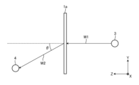
- FIG. 2 is a diagram for explaining how to use the radio wave refraction plate.
- the radio wave refraction plate 1a is configured to refract the radio wave W1 transmitted by the base station 3 at a predetermined angle and emit the refracted wave W2 to the receiving device 4.
- the angle between the straight line projecting the refracted wave W2 onto the XZ plane and the Z axis is defined as ⁇
- the angle between the straight line projecting the refracted wave W2 onto the XY plane and the Y axis is defined as ⁇ .
- the phase distribution of the radio wave refraction plate 1a is set according to the desired angle ⁇ and angle ⁇ . Typically, the phase distribution of the radio wave refraction plate 1a is determined based on the following formula (1).
- ⁇ is the phase difference between adjacent unit structures
- k is the wave number of the radio wave
- dx is the distance between adjacent unit structures in the X direction
- dy is the distance between adjacent unit structures in the Y direction.
- the refracted wave W2 emitted by the radio wave refraction plate 1a designed based on formula (1) has a problem in that the beam width is narrow in the far-field region.
- the receiving device 4 if the receiving device 4 is installed in the far-field region, the receiving device 4 may not be able to properly receive the refracted wave W2. Therefore, this disclosure provides a radio wave refraction plate that can widen the beam width of the refracted wave W2 even in the far-field region.
- Fig. 3 is a diagram showing a configuration example of the radio wave refraction plate according to the first embodiment.
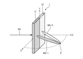
- the radio wave refraction plate 1 includes a first radio wave refraction region 11 and a second radio wave refraction region 12.
- the radio wave refraction plate 1 is configured to receive radio waves W1 transmitted by the base station 3 and emit them toward the vicinity of point C in the XZ plane (refractive surface).
- the radio wave refraction plate 1 is divided in the Y-axis direction (horizontal direction) in the XY plane.
- the first radio wave refraction region 11 and the second radio wave refraction region 12 are regions obtained by dividing the radio wave refraction plate 1 perpendicularly to the refraction surface.
- the first radio wave refraction region 11 is configured to refract the received radio wave W1 and emit the refracted wave W2-1 toward the vicinity of point C.
- the second radio wave refraction region 12 is configured to refract the received radio wave W1 and emit the refracted wave W2-2 toward the vicinity of point C.
- the first radio wave refraction region 11 and the second radio wave refraction region 12 are configured to have different refraction angles of the radio wave W1.
- the first radio wave refraction region 11 and the second radio wave refraction region 12 are configured to have different phase distributions, for example, to have different refraction angles of the radio wave W1. That is, the refraction angles of the radio wave W1 can be set independently for the first radio wave refraction region 11 and the second radio wave refraction region 12.
- the refraction angle of the radio wave W1 is set for each radio wave refraction region, thereby widening the beam width in the ⁇ direction of the refracted wave toward point C.
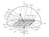
- FIG. 4 is a diagram for explaining the beam width of the refracted wave in the first embodiment.
- the first radio wave refraction region 11 emits a refracted wave W2-1 obtained by refracting the radio wave W1 toward the vicinity of point C.
- Region R11 shows the beam width of the refracted wave W2-1 on a hemisphere including point C.
- the second radio wave refraction region 12 emits a refracted wave W2-2 obtained by refracting the radio wave W1 toward the vicinity of point C.
- Region R12 shows the beam width of the refracted wave W2-2 on a hemisphere including point C.
- Region R1 shows the beam width of the refracted wave obtained by refracting the radio wave W1 by the radio wave refraction plate 1 on a hemisphere including point C.
- Region R1 is a region that combines regions R11 and R12. Regions R11 and R12 are aligned in the ⁇ direction. That is, in the first embodiment, by dividing the radio wave refraction plate 1 into multiple radio wave refraction regions, such as the first radio wave refraction region 11 and the second radio wave refraction region 12, it is possible to widen the beam width in the ⁇ direction on the hemisphere including point C.
- the first radio wave refraction region 11 and the second radio wave refraction region 12 may be the same size or different sizes.
- the first radio wave refraction region 11 and the second radio wave refraction region 12 may be formed, for example, by forming two regions with different phase distributions in one radio wave refraction plate 1.
- the first radio wave refraction region 11 and the second radio wave refraction region 12 may be formed, for example, by arranging two radio wave refraction plates with different phase distributions side by side.
- the two radio wave refraction plates may be arranged so as to be in contact with each other or with a predetermined distance between them.
- the radio wave refraction plate 1 has been described as including two radio wave refraction regions, the first radio wave refraction region 11 and the second radio wave refraction region 12, but the present disclosure is not limited to this.
- the radio wave refraction plate 1 may include three or more radio wave refraction regions.
- the radio wave refraction plate 1 is perpendicular to the refraction surface and includes multiple radio wave refraction regions in which the refraction angles of the radio waves W1 are different. This makes it possible for the first embodiment to widen the beam width in the distant region of the refracted waves refracted by the radio wave refraction plate 1.
- FIG. 5 is a diagram showing a configuration example of the radio wave refraction plate according to the second embodiment.
- the radio wave refraction plate 1A has a first radio wave refraction region 11A, a second radio wave refraction region 12A, a third radio wave refraction region 13A, and a fourth radio wave refraction region 14A.
- the radio wave refraction plate 1A is divided in both the X-axis direction (vertical direction) and the Y-axis direction (horizontal direction) in the XY plane.
- the first radio wave refraction region 11A is configured to refract the radio wave W1 and emit a refracted wave W2A-1 toward the vicinity of point C.
- the second radio wave refraction region 12A is configured to refract the radio wave W1 and emit a refracted wave W2A-2 toward the vicinity of point C.
- the third radio wave refraction region 13A is configured to refract the radio wave W1 and emit a refracted wave W2A-3 toward the vicinity of point C.
- the fourth radio wave refraction region 14A is configured to refract the radio wave W1 and emit a refracted wave W2A-4 toward the vicinity of point C.
- the first radio wave refraction region 11A to the fourth radio wave refraction region 14A are configured to have different refraction angles of the radio wave W1.
- the first radio wave refraction region 11A to the fourth radio wave refraction region 14A are configured to have different phase distributions, for example, to have different refraction angles of the radio wave W1. That is, the first radio wave refraction region 11A to the fourth radio wave refraction region 14A can each set the refraction angle of the radio wave W1 independently.
- the refraction angle of the radio wave W1 is set for each radio wave refraction region, thereby making it possible to widen the beam widths in the ⁇ and ⁇ directions of the refracted wave on the hemisphere including point C.
- Region R11A shows the beam width on the hemisphere including point C of refracted wave W2A-1.
- Region R12A shows the beam width on the hemisphere including point C of refracted wave W2A-2.
- Region R13A shows the beam width on the hemisphere including point C of refracted wave W2A-3.
- Region R14A shows the beam width on the hemisphere including point C of refracted wave W2A-4.
- Region R1A is the combined region of regions R11A, R12A, R13A, and R14A. Regions R11A and R12A are aligned in the ⁇ direction. Regions R13A and R14A are aligned in the ⁇ direction. Regions R11A and R13A are aligned in the ⁇ direction.
- Regions R12A and R14A are aligned in the ⁇ direction. Regions R11A and R12A, and regions R13A and R14A are aligned in a direction perpendicular to the refraction surface. Regions R11A and R13A, and regions R12A and R14A are aligned in a direction parallel to the refraction surface. That is, in the second embodiment, by dividing the radio wave refraction plate 1A into a plurality of radio wave refraction regions, such as the first radio wave refraction region 11A to the fourth radio wave refraction region 14A, it is possible to widen the beam width in the ⁇ direction and the ⁇ direction on the hemisphere including point C.
- the first radio wave refraction region 11A to the fourth radio wave refraction region 14A may each be the same size or different sizes.
- the first radio wave refraction region 11A to the fourth radio wave refraction region 14A may each be formed, for example, by forming four regions with different phase distributions in one radio wave refraction plate 1A.
- the first radio wave refraction region 11A to the fourth radio wave refraction region 14 may each be formed, for example, by arranging four radio wave refraction plates with different phase distributions.
- the four radio wave refraction plates may be arranged so as to be in contact with each other, or may be arranged with a predetermined interval between them.
- the radio wave refraction plate 1A has been described as including four radio wave refraction regions, the first radio wave refraction region 11A to the fourth radio wave refraction region 14A, but the present disclosure is not limited to this.
- the radio wave refraction plate 1A may include five or more radio wave refraction regions.
- the radio wave refraction plate 1A includes multiple radio wave refraction regions that are perpendicular and parallel to the refraction surface and have different refraction angles for the radio waves W1. This allows the second embodiment to more appropriately widen the beam width in the distant region of the refracted waves refracted by the radio wave refraction plate 1A.
- [Third embodiment] 6 is a diagram for explaining a method of refracting radio waves using a radio wave refraction plate according to the third embodiment.
- point C which is the center of the region where the refracted wave is to be expanded, is included within the beam widths in the ⁇ and ⁇ directions of the refracted waves from each of the first radio wave refraction region 11A to the fourth radio wave refraction region 14A, the received power at the position of point C may become larger than necessary, resulting in a narrow beam width of the refracted wave in the direction of point C.
- the refraction angle is set so that point C is not included within the beam width in both the ⁇ and ⁇ directions of the refracted wave from at least one of the multiple radio wave refraction regions. Also, in the third embodiment, the refraction angle of the radio wave refraction region that emits the refracted wave that is set so that point C is not included is set so that it overlaps within the half-width with the refracted wave from the radio wave refraction region that is set so that point C is included in both the ⁇ and ⁇ directions.
- FIG. 7 is a diagram for explaining the refraction angle of the radio wave refraction region according to the third embodiment.
- the horizontal axis indicates the refraction angle [deg (degrees)] in the ⁇ direction, and the vertical axis indicates the gain [dB (decibels)].
- Line 101 indicates the position of point C.
- Beam pattern 102 shows the gain characteristics of the refracted wave from the radio wave refraction region in which the refraction angle is set so that point C is not included within the beam width.
- Beam pattern 103 shows the gain characteristics of the refracted wave from the radio wave refraction region in which the beam width is set so that point C is included within the beam width.
- Half-width 104 indicates the half-width of the refracted wave from the radio wave refraction region where the refraction angle is set so that point C is not included within the beam width.
- Half-width 105 indicates the half-width of the refracted wave from the radio wave refraction region where the refraction angle is set so that point C is included within the beam width. As shown in FIG. 7, point C is located outside half-width 104 and within half-width 105.
- the third embodiment can prevent the received power at the position of point C from becoming greater than necessary. As a result, the third embodiment can prevent the beam width at a position on the hemisphere that includes point C from becoming narrow.
- FIG. 8 is a diagram showing the gain characteristics of the refracted wave according to a comparative example of the fourth embodiment.
- the horizontal axis indicates the refraction angle [deg]
- the vertical axis indicates the gain [dB].
- the beam pattern 110 shows the gain characteristics of the refracted wave emitted by the entire radio wave refraction plate 1 (see FIG. 4).
- the beam pattern 111 shows the gain characteristics of the refracted wave W2-1 emitted by the first radio wave refraction region 11 (see FIG. 4).
- the beam pattern 112 shows the gain characteristics of the refracted wave 2-2 emitted by the second radio wave refraction region 12 (see FIG. 4).
- the beam pattern 110 is a superposition of the beam pattern 111 and the beam pattern 112.
- the refracted wave does not form a flat beam pattern.
- beam pattern 111 has null point P1
- beam pattern 112 has null point P2.
- Null point P1 and null point P2 are located within range 113. Therefore, when beam pattern 111 and beam pattern 112 are superimposed, ripples occur in beam pattern 110 in range 113, and a flat beam pattern cannot be obtained in range 113. Therefore, in the fourth embodiment, a refracted wave with a flat beam pattern is formed by appropriately setting the aperture size of each radio wave refraction region.
- ⁇ be the range in which you want to create a flat beam pattern.
- the beam pattern should be formed between the first null on the high frequency side and the first null on the low frequency side, so the following equation (3) holds.
- FIG. 9 is a diagram showing a configuration example of a radio wave refraction plate according to the fourth embodiment.
- radio wave refraction plate 1B has a first radio wave refraction region 11B, a second radio wave refraction region 12B, a third radio wave refraction region 13B, and a fourth radio wave refraction region 14B.
- Radio wave refraction plate 1B is divided in the Y-axis direction (horizontal direction) on the XY plane.
- the sizes of the openings of first radio wave refraction region 11B to fourth radio wave refraction region 14B are each determined so as to satisfy formula (4).
- the first radio wave refraction region 11B is configured to refract the radio wave W1 and emit a refracted wave W2B-1.
- the first radio wave refraction region 11B is configured to refract the radio wave W1 by 42.5° in the ⁇ direction, for example.
- the second radio wave refraction region 12B is configured to refract the radio wave W1 and emit a refracted wave W2B-2.
- the second radio wave refraction region 12B is configured, for example, to refract the radio wave W1 by 44° in the ⁇ direction.
- the third radio wave refraction region 13B is configured to refract the radio wave W1 and emit a refracted wave W2B-3.
- the third radio wave refraction region 13B is configured, for example, to refract the radio wave W1 by 46° in the ⁇ direction.
- the fourth radio wave refraction region 14B is configured to refract the radio wave W1 and emit a refracted wave W2B-4.
- the fourth radio wave refraction region 14B is configured, for example, to refract the radio wave W1 by 50° in the ⁇ direction.
- the refraction angle of the radio wave W1 in the first radio wave refraction region 11B is configured to be the gentlest
- the refraction angle of the radio wave W1 in the fourth radio wave refraction region 14B is configured to be the steepest.
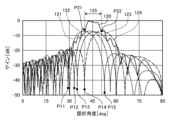
- FIG. 10 is a diagram showing the gain characteristics of the refracted wave according to the fourth embodiment.
- the horizontal axis indicates the refraction angle [deg]
- the vertical axis indicates the gain [dB].
- Beam pattern 120 indicates the gain characteristics of the refracted wave emitted by the entire radio wave refraction plate 1B.
- Beam pattern 121 indicates the gain characteristics of the refracted wave W2B-1 emitted by the first radio wave refraction region 11B.
- Beam pattern 122 indicates the gain characteristics of the refracted wave 2B-2 emitted by the second radio wave refraction region 12B.
- Beam pattern 123 indicates the gain characteristics of the refracted wave W2B-3 emitted by the third radio wave refraction region 13B.
- Beam pattern 124 indicates the gain characteristics of the refracted wave W2B-4 emitted by the fourth radio wave refraction region 14B.
- Beam pattern 120 is a superposition of beam pattern 121, beam pattern 122, beam pattern 123, and beam pattern 124.
- Beam pattern 121 has a null point P11.
- Beam pattern 122 has a null point P12.
- Beam pattern 123 has a null point P13.
- Beam pattern 124 has a null point P14.
- the refracted wave has a flat beam pattern with less ripples than beam pattern 110 shown in FIG. 8. This is because null point P11, null point P12, null point P13, and null point P14 are located outside range 125. Therefore, in the fourth embodiment, when beam pattern 121, beam pattern 122, beam pattern 123, and beam pattern 124 are superimposed, it is possible to prevent the occurrence of ripples in range 125 of beam pattern 120.
- range 125 which is a flat beam pattern, is formed between the first null (null point P14) on the low frequency side of beam pattern 124 and the first null (null point P15) on the high frequency side of beam pattern 121.
- angles of the peak point P21 and the null point P15 of the beam pattern 121 are ⁇ a and ⁇ a1H , respectively.
- the angles of the peak point P22 and the null point P14 of the beam pattern 124 are ⁇ d and ⁇ d1L , respectively. If the range 125 is ⁇ , ⁇ is expressed by the following equation (5).
- the size d of each opening can be calculated based on equations (2) to (4). Then, ⁇ a and ⁇ d can be calculated by substituting the calculated size d of each opening into equation (7).
- the fourth embodiment can calculate the size of the aperture based on the angle of the null point of the refracted wave emitted from each radio wave refraction region. The fourth embodiment can then calculate the angle of the peak point of the refracted wave emitted from each radio wave refraction region based on the calculated size of the aperture. This allows the fourth embodiment to form a more appropriately flat beam pattern within a desired range.
- Fig. 11 is a diagram for explaining the refraction angle in the first direction of the radio wave refraction plate according to the fifth embodiment.
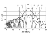
- Fig. 12 is a diagram showing the gain characteristic of the refracted wave in the first direction of the radio wave refraction plate according to the fifth embodiment.
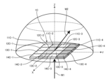
- Fig. 13 is a diagram for explaining the refraction angle in the second direction of the radio wave refraction plate according to the fifth embodiment.
- Fig. 14 is a diagram for explaining the refraction angle in the second direction of the radio wave refraction plate according to the fifth embodiment.
- the radio wave refraction plate 1C includes a first radio wave refraction region 11C-1, a first radio wave refraction region 11C-2, a first radio wave refraction region 11C-3, a first radio wave refraction region 11C-4, a second radio wave refraction region 12C-1, a second radio wave refraction region 12C-2, a second radio wave refraction region 12C-3, a second radio wave refraction region 12C-4, a third radio wave refraction region 13C-1, a third radio wave refraction region 13C-2, a third radio wave refraction region 13C-3, a third radio wave refraction region 13C-4, a fourth radio wave refraction region 14C-1, a fourth radio wave refraction region 14C-2, a fourth radio wave refraction region 14C-3, and a fourth radio wave refraction region 14C-4.
- the radio wave refraction plate 1C includes 16 radio wave refraction regions.
- the radio wave refraction plate 1C is configured to refract radio waves W1 using 16 radio wave refraction regions and emit refracted waves W2.
- the radio wave refraction plate 1C is divided in both the X-axis direction (vertical direction) and the Y-axis direction (horizontal direction) in the XY plane.
- the first radio wave refraction region 11C-1, the first radio wave refraction region 11C-2, the first radio wave refraction region 11C-3, and the first radio wave refraction region 11C-4 may be collectively referred to as the first radio wave refraction region group.
- the second radio wave refraction region 12C-1, the second radio wave refraction region 12C-2, the second radio wave refraction region 12C-3, and the second radio wave refraction region 12C-4 may be collectively referred to as the second radio wave refraction region group.
- the third radio wave refraction region 13C-1, the third radio wave refraction region 13C-2, the third radio wave refraction region 13C-3, and the third radio wave refraction region 13C-4 may be collectively referred to as the third radio wave refraction region group.
- the fourth radio wave refraction region 14C-1, the fourth radio wave refraction region 14C-2, the fourth radio wave refraction region 14C-3, and the fourth radio wave refraction region 14C-4 are sometimes collectively referred to as the fourth radio wave refraction region group.
- Beam pattern 130 indicates the gain characteristics of the refracted waves in the ⁇ direction emitted by the entire radio wave refraction plate 1C.
- Beam pattern 131 indicates the gain characteristics of the refracted waves emitted by the first radio wave refraction area group.
- Beam pattern 132 indicates the gain characteristics of the refracted waves emitted by the second radio wave refraction area group.
- Beam pattern 133 indicates the gain characteristics of the refracted waves emitted by the third radio wave refraction area group.
- Beam pattern 134 indicates the gain characteristics of the refracted waves emitted by the fourth radio wave refraction area group.
- Beam pattern 130 is a superposition of beam pattern 131, beam pattern 132, beam pattern 133, and beam pattern 134.
- radio wave refraction plate 1C can emit a refracted wave with a flat beam pattern in range 135 between the peak angle of beam pattern 131 and the peak angle of beam pattern 134.
- FIG. 13 is a diagram for explaining the refraction angle in the second direction of the radio wave refraction plate according to the fifth embodiment.
- the first radio wave refraction region 11C-4, the second radio wave refraction region 12C-4, the third radio wave refraction region 13C-4, and the fourth radio wave refraction region 14C-4 may be collectively referred to as the fifth radio wave refraction region group.
- the first radio wave refraction region 11C-3, the second radio wave refraction region 12C-3, the third radio wave refraction region 13C-3, and the fourth radio wave refraction region 14C-3 may be collectively referred to as the sixth radio wave refraction region group.
- the first radio wave refraction region 11C-2, the second radio wave refraction region 12C-2, the third radio wave refraction region 13C-2, and the fourth radio wave refraction region 14C-2 may be collectively referred to as the seventh radio wave refraction region group.
- the first radio wave refraction region 11C-1, the second radio wave refraction region 12C-1, the third radio wave refraction region 13C-1, and the fourth radio wave refraction region 14C-1 are sometimes collectively referred to as the eighth radio wave refraction region group.
- Beam pattern 140 indicates the gain characteristics of the refracted waves in the ⁇ direction emitted by the entire radio wave refraction plate 1C.
- Beam pattern 141 indicates the gain characteristics of the refracted waves emitted by the fifth radio wave refraction area group.
- Beam pattern 142 indicates the gain characteristics of the refracted waves emitted by the sixth radio wave refraction area group.
- Beam pattern 143 indicates the gain characteristics of the refracted waves emitted by the seventh radio wave refraction area group.
- Beam pattern 144 indicates the gain characteristics of the refracted waves emitted by the eighth radio wave refraction area group.
- Beam pattern 140 is a superposition of beam pattern 141, beam pattern 142, beam pattern 143, and beam pattern 144.
- radio wave refraction plate 1C can emit a refracted wave with a flat beam pattern in range 145 between the peak angle of beam pattern 141 and the peak angle of beam pattern 144.
- the size d of each opening is calculated based on formulas (2) to (4), and the calculated size d of each opening is substituted into formula (7) to calculate ⁇ a and ⁇ d .
- Formulas (5) to (7) are similar in the ⁇ direction, so the explanation will be omitted.
- the fifth embodiment can calculate the size of the aperture based on the angle of the null point of the refracted wave emitted from each radio wave refraction region.
- the fifth embodiment can then calculate the angle of the peak point of the refracted wave emitted from each radio wave refraction region based on the calculated size of the aperture. This allows the fifth embodiment to form a more appropriately flat beam pattern within a desired range.
- Radio wave refraction plate 3 Base station 4
Landscapes
- Aerials With Secondary Devices (AREA)
Priority Applications (2)
| Application Number | Priority Date | Filing Date | Title |
|---|---|---|---|
| JP2024574389A JPWO2024161966A1 (https=) | 2023-01-31 | 2024-01-15 | |
| EP24749920.5A EP4661214A1 (en) | 2023-01-31 | 2024-01-15 | Radio wave refraction plate |
Applications Claiming Priority (2)
| Application Number | Priority Date | Filing Date | Title |
|---|---|---|---|
| JP2023-013240 | 2023-01-31 | ||
| JP2023013240 | 2023-01-31 |
Publications (1)
| Publication Number | Publication Date |
|---|---|
| WO2024161966A1 true WO2024161966A1 (ja) | 2024-08-08 |
Family
ID=92146458
Family Applications (1)
| Application Number | Title | Priority Date | Filing Date |
|---|---|---|---|
| PCT/JP2024/000797 Ceased WO2024161966A1 (ja) | 2023-01-31 | 2024-01-15 | 電波屈折板 |
Country Status (3)
| Country | Link |
|---|---|
| EP (1) | EP4661214A1 (https=) |
| JP (1) | JPWO2024161966A1 (https=) |
| WO (1) | WO2024161966A1 (https=) |
Cited By (1)
| Publication number | Priority date | Publication date | Assignee | Title |
|---|---|---|---|---|
| WO2026004994A1 (ja) * | 2024-06-26 | 2026-01-02 | 京セラ株式会社 | 電波制御板 |
Citations (3)
| Publication number | Priority date | Publication date | Assignee | Title |
|---|---|---|---|---|
| JP2015231182A (ja) | 2014-06-06 | 2015-12-21 | 日本電信電話株式会社 | メタマテリアル受動素子 |
| JP2021141547A (ja) * | 2020-03-09 | 2021-09-16 | オムロン株式会社 | アンテナ装置及びレーダ装置 |
| WO2022091986A1 (ja) * | 2020-10-30 | 2022-05-05 | 京セラ株式会社 | 通信システム、通信方法、および電波屈折板の設置方法 |
Family Cites Families (2)
| Publication number | Priority date | Publication date | Assignee | Title |
|---|---|---|---|---|
| KR102482247B1 (ko) * | 2018-08-13 | 2022-12-28 | 삼성전자주식회사 | 평면 렌즈를 포함하는 안테나 장치 |
| JP7741024B2 (ja) * | 2021-04-19 | 2025-09-17 | 京セラ株式会社 | 電波屈折板 |
-
2024
- 2024-01-15 JP JP2024574389A patent/JPWO2024161966A1/ja active Pending
- 2024-01-15 WO PCT/JP2024/000797 patent/WO2024161966A1/ja not_active Ceased
- 2024-01-15 EP EP24749920.5A patent/EP4661214A1/en active Pending
Patent Citations (3)
| Publication number | Priority date | Publication date | Assignee | Title |
|---|---|---|---|---|
| JP2015231182A (ja) | 2014-06-06 | 2015-12-21 | 日本電信電話株式会社 | メタマテリアル受動素子 |
| JP2021141547A (ja) * | 2020-03-09 | 2021-09-16 | オムロン株式会社 | アンテナ装置及びレーダ装置 |
| WO2022091986A1 (ja) * | 2020-10-30 | 2022-05-05 | 京セラ株式会社 | 通信システム、通信方法、および電波屈折板の設置方法 |
Non-Patent Citations (2)
| Title |
|---|
| N. YU, P. GENEVET, M. A. KATS, F. AIETA, J.-P. TETIENNE, F. CAPASSO, Z. GABURRO: "Light Propagation with Phase Discontinuities: Generalized Laws of Reflection and Refraction", SCIENCE, AMERICAN ASSOCIATION FOR THE ADVANCEMENT OF SCIENCE, US, vol. 334, no. 6054, 21 October 2011 (2011-10-21), US , pages 333 - 337, XP055393074, ISSN: 0036-8075, DOI: 10.1126/science.1210713 * |
| See also references of EP4661214A1 |
Cited By (1)
| Publication number | Priority date | Publication date | Assignee | Title |
|---|---|---|---|---|
| WO2026004994A1 (ja) * | 2024-06-26 | 2026-01-02 | 京セラ株式会社 | 電波制御板 |
Also Published As
| Publication number | Publication date |
|---|---|
| JPWO2024161966A1 (https=) | 2024-08-08 |
| EP4661214A1 (en) | 2025-12-10 |
Similar Documents
| Publication | Publication Date | Title |
|---|---|---|
| JP6057380B2 (ja) | 交差偏波補償を備えた反射器アレイアンテナおよびそのようなアンテナを製造するための方法 | |
| JP5352645B2 (ja) | マルチビームリフレクトアレイ | |
| US9537221B2 (en) | Reflectarray | |
| CN109698407B (zh) | 一种基于超表面的四波束涡旋场卡塞格伦透镜天线 | |
| US10911963B1 (en) | Active antenna system | |
| JP5410558B2 (ja) | リフレクトアレー及び設計方法 | |
| WO2022092029A1 (ja) | 可変リフレクトアレーおよび可変リフレクトアレーの設計方法 | |
| US11189933B2 (en) | Phase control device, antenna system, and method of controlling phase of electromagnetic wave | |
| CN115548692A (zh) | 透镜单元、透镜阵列以及阵列天线 | |
| WO2024161966A1 (ja) | 電波屈折板 | |
| CN113519089A (zh) | 移动体用天线装置及通信装置 | |
| JP2006517073A (ja) | 位相アレイアンテナおよび素子間相互結合制御方法 | |
| WO2024162166A1 (ja) | 電波反射板 | |
| JP6409676B2 (ja) | 衛星通信用アレイアンテナおよびアンテナ | |
| JP2018137743A (ja) | リフレクトアレーアンテナ | |
| WO2025004939A1 (ja) | 通信システム、および電波制御板の設置方法 | |
| JP5469724B1 (ja) | リフレクトアレー | |
| US10862206B2 (en) | Antenna device | |
| JP2021027465A (ja) | フェーズドアレーアンテナおよびその配列方法 | |
| JP7767632B2 (ja) | 電波反射板 | |
| JP5993319B2 (ja) | リフレクトアレー及び素子 | |
| US20260058369A1 (en) | Radio wave control plate | |
| JP7846472B2 (ja) | フェーズドアレーアンテナ、移動体搭載型通信システム、および、プログラム | |
| JP7634715B1 (ja) | アンテナ装置および電波制御板 | |
| CN118431777B (zh) | 一种面向宽角波束扫描的异构天线阵列设计方法 |
Legal Events
| Date | Code | Title | Description |
|---|---|---|---|
| 121 | Ep: the epo has been informed by wipo that ep was designated in this application |
Ref document number: 24749920 Country of ref document: EP Kind code of ref document: A1 |
|
| ENP | Entry into the national phase |
Ref document number: 2024574389 Country of ref document: JP Kind code of ref document: A |
|
| WWE | Wipo information: entry into national phase |
Ref document number: 2024574389 Country of ref document: JP |
|
| NENP | Non-entry into the national phase |
Ref country code: DE |
|
| WWP | Wipo information: published in national office |
Ref document number: 2024749920 Country of ref document: EP |