WO2024157369A1 - 冷媒分配器及び熱交換器 - Google Patents
冷媒分配器及び熱交換器 Download PDFInfo
- Publication number
- WO2024157369A1 WO2024157369A1 PCT/JP2023/002189 JP2023002189W WO2024157369A1 WO 2024157369 A1 WO2024157369 A1 WO 2024157369A1 JP 2023002189 W JP2023002189 W JP 2023002189W WO 2024157369 A1 WO2024157369 A1 WO 2024157369A1
- Authority
- WO
- WIPO (PCT)
- Prior art keywords
- plate
- path
- return path
- refrigerant
- flat tube
- Prior art date
- Legal status (The legal status is an assumption and is not a legal conclusion. Google has not performed a legal analysis and makes no representation as to the accuracy of the status listed.)
- Ceased
Links
Images











Classifications
-
- F—MECHANICAL ENGINEERING; LIGHTING; HEATING; WEAPONS; BLASTING
- F28—HEAT EXCHANGE IN GENERAL
- F28D—HEAT-EXCHANGE APPARATUS, NOT PROVIDED FOR IN ANOTHER SUBCLASS, IN WHICH THE HEAT-EXCHANGE MEDIA DO NOT COME INTO DIRECT CONTACT
- F28D1/00—Heat-exchange apparatus having stationary conduit assemblies for one heat-exchange medium only, the media being in contact with different sides of the conduit wall, in which the other heat-exchange medium is a large body of fluid, e.g. domestic or motor car radiators
- F28D1/02—Heat-exchange apparatus having stationary conduit assemblies for one heat-exchange medium only, the media being in contact with different sides of the conduit wall, in which the other heat-exchange medium is a large body of fluid, e.g. domestic or motor car radiators with heat-exchange conduits immersed in the body of fluid
- F28D1/04—Heat-exchange apparatus having stationary conduit assemblies for one heat-exchange medium only, the media being in contact with different sides of the conduit wall, in which the other heat-exchange medium is a large body of fluid, e.g. domestic or motor car radiators with heat-exchange conduits immersed in the body of fluid with tubular conduits
- F28D1/053—Heat-exchange apparatus having stationary conduit assemblies for one heat-exchange medium only, the media being in contact with different sides of the conduit wall, in which the other heat-exchange medium is a large body of fluid, e.g. domestic or motor car radiators with heat-exchange conduits immersed in the body of fluid with tubular conduits the conduits being straight
- F28D1/0535—Heat-exchange apparatus having stationary conduit assemblies for one heat-exchange medium only, the media being in contact with different sides of the conduit wall, in which the other heat-exchange medium is a large body of fluid, e.g. domestic or motor car radiators with heat-exchange conduits immersed in the body of fluid with tubular conduits the conduits being straight the conduits having a non-circular cross-section
- F28D1/05366—Assemblies of conduits connected to common headers, e.g. core type radiators
- F28D1/05391—Assemblies of conduits connected to common headers, e.g. core type radiators with multiple rows of conduits or with multi-channel conduits combined with a particular flow pattern, e.g. multi-row multi-stage radiators
-
- F—MECHANICAL ENGINEERING; LIGHTING; HEATING; WEAPONS; BLASTING
- F25—REFRIGERATION OR COOLING; COMBINED HEATING AND REFRIGERATION SYSTEMS; HEAT PUMP SYSTEMS; MANUFACTURE OR STORAGE OF ICE; LIQUEFACTION SOLIDIFICATION OF GASES
- F25B—REFRIGERATION MACHINES, PLANTS OR SYSTEMS; COMBINED HEATING AND REFRIGERATION SYSTEMS; HEAT PUMP SYSTEMS
- F25B39/00—Evaporators; Condensers
- F25B39/02—Evaporators
- F25B39/028—Evaporators having distributing means
-
- F—MECHANICAL ENGINEERING; LIGHTING; HEATING; WEAPONS; BLASTING
- F25—REFRIGERATION OR COOLING; COMBINED HEATING AND REFRIGERATION SYSTEMS; HEAT PUMP SYSTEMS; MANUFACTURE OR STORAGE OF ICE; LIQUEFACTION SOLIDIFICATION OF GASES
- F25B—REFRIGERATION MACHINES, PLANTS OR SYSTEMS; COMBINED HEATING AND REFRIGERATION SYSTEMS; HEAT PUMP SYSTEMS
- F25B39/00—Evaporators; Condensers
- F25B39/04—Condensers
-
- F—MECHANICAL ENGINEERING; LIGHTING; HEATING; WEAPONS; BLASTING
- F28—HEAT EXCHANGE IN GENERAL
- F28F—DETAILS OF HEAT-EXCHANGE AND HEAT-TRANSFER APPARATUS, OF GENERAL APPLICATION
- F28F9/00—Casings; Header boxes; Auxiliary supports for elements; Auxiliary members within casings
- F28F9/02—Header boxes; End plates
- F28F9/0219—Arrangements for sealing end plates into casing or header box; Header box sub-elements
- F28F9/0221—Header boxes or end plates formed by stacked elements
-
- F—MECHANICAL ENGINEERING; LIGHTING; HEATING; WEAPONS; BLASTING
- F28—HEAT EXCHANGE IN GENERAL
- F28F—DETAILS OF HEAT-EXCHANGE AND HEAT-TRANSFER APPARATUS, OF GENERAL APPLICATION
- F28F9/00—Casings; Header boxes; Auxiliary supports for elements; Auxiliary members within casings
- F28F9/02—Header boxes; End plates
- F28F9/026—Header boxes; End plates with static flow control means, e.g. with means for uniformly distributing heat exchange media into conduits
- F28F9/0278—Header boxes; End plates with static flow control means, e.g. with means for uniformly distributing heat exchange media into conduits in the form of stacked distribution plates or perforated plates arranged over end plates
-
- F—MECHANICAL ENGINEERING; LIGHTING; HEATING; WEAPONS; BLASTING
- F25—REFRIGERATION OR COOLING; COMBINED HEATING AND REFRIGERATION SYSTEMS; HEAT PUMP SYSTEMS; MANUFACTURE OR STORAGE OF ICE; LIQUEFACTION SOLIDIFICATION OF GASES
- F25B—REFRIGERATION MACHINES, PLANTS OR SYSTEMS; COMBINED HEATING AND REFRIGERATION SYSTEMS; HEAT PUMP SYSTEMS
- F25B13/00—Compression machines, plants or systems, with reversible cycle
-
- F—MECHANICAL ENGINEERING; LIGHTING; HEATING; WEAPONS; BLASTING
- F28—HEAT EXCHANGE IN GENERAL
- F28D—HEAT-EXCHANGE APPARATUS, NOT PROVIDED FOR IN ANOTHER SUBCLASS, IN WHICH THE HEAT-EXCHANGE MEDIA DO NOT COME INTO DIRECT CONTACT
- F28D21/00—Heat-exchange apparatus not covered by any of the groups F28D1/00 - F28D20/00
- F28D2021/0019—Other heat exchangers for particular applications; Heat exchange systems not otherwise provided for
- F28D2021/0068—Other heat exchangers for particular applications; Heat exchange systems not otherwise provided for for refrigerant cycles
Definitions
- This disclosure relates to a refrigerant distributor, such as a stacked circulation header, and a heat exchanger having a refrigerant distributor, and in particular to a distribution structure for the downward flow of refrigerant.
- Some refrigerant distributors are made of multiple stacked plate-like members extending in the vertical direction, and are provided with an outward path that extends in the vertical direction and through which the refrigerant flows upward from a discharge hole provided at the bottom, a return path that extends in the vertical direction and through which the refrigerant flows downward, upper and lower communication paths that connect the outward path and return path, and multiple flat tube insertion holes into which the ends of flat tubes are inserted (see, for example, Patent Document 1).
- second flow paths are provided that are individually and directly connected to each of the flat tube insertion holes, and each second flow path is connected to the return path via a communication port. That is, in the refrigerant distributor of Patent Document 1, the flat tube insertion holes are connected to the return path by the second flow paths and the communication ports.
- the width of the second flow path is greater than the width of the return path, but the width of the communication port is smaller than the width of the return path. Therefore, while the refrigerant flows out of the return path and passes through the communication port, the refrigerant may gain flow inertia in the stacking direction. As a result, the refrigerant is less likely to diffuse laterally in the second flow path, which is the space between the communication port and the end of the flat tube, and it may be difficult to flow the refrigerant uniformly laterally into the flat tube.
- the present disclosure was made against the background of the above-mentioned problems, and provides a refrigerant distributor and heat exchanger that can cause refrigerant to flow more evenly into the flat tubes than conventional devices.
- the refrigerant distributor according to the present disclosure is formed by stacking a plurality of plate-like members each extending in the vertical direction, a plurality of flat tube insertion holes into which the ends of flat tubes are inserted are formed in the vertical direction, and a refrigerant inlet portion is formed.
- the flow path extends in the vertical direction and has a forward path in which the refrigerant flows upward with the inlet portion connected to its lower end, a return path that extends in the vertical direction and in which the refrigerant flows downward, an upper communication path and a lower communication path that annularly connect the forward path and the return path, and a plurality of flat tube communication paths that individually connect the plurality of flat tube insertion holes to the return path, and the width of the flat tube communication path is equal to or greater than the width of the return path across the stacking direction when the plurality of plate-like members are viewed in the stacking direction.
- the refrigerant distributor according to the present disclosure is a refrigerant distributor which is formed by stacking a plurality of plate-shaped members each extending in the vertical direction, including an inlet plate member in which a refrigerant inlet is formed, and an insertion side plate member in which a plurality of flat tube insertion holes into which ends of flat tubes are inserted are formed in the vertical direction, and the refrigerant flowing in from the inlet is branched and flows into a plurality of the flat tubes, the plurality of plate-shaped members being formed with an outward path extending in the vertical direction, and between the inlet plate member and the insertion side plate member, an outward path plate member provided adjacent to the inlet plate member so that the inlet is connected to a lower end of the outward path, and a return path extending in the vertical direction are formed,
- the device has a return path plate member provided between the outward path plate member and the insertion side plate member and adjacent to the outward path plate member, and a communication path plate member provided between the return
- the refrigerant distributor according to the present disclosure is a refrigerant distributor which is formed by stacking a plurality of plate-shaped members each extending in the vertical direction, including an inlet plate member in which a refrigerant inlet is formed, and an insertion side plate member in which a plurality of flat tube insertion holes into which ends of flat tubes are inserted are formed in the vertical direction, and the refrigerant flowing in from the inlet is branched and flows into a plurality of the flat tubes, the plurality of plate-shaped members are formed with an outward path extending in the vertical direction, and a portion of a return path which extends in the vertical direction while meandering in the stacking direction, a first plate-shaped member provided adjacent to the inlet plate member between the inlet plate member and the insertion side plate member so that the inlet is connected to the lower end of the outward path, and the remaining portion of the return path
- a second plate-shaped member is provided between the first plate-shaped member and the insertion side plate-shaped member and adjacent to
- first plate-shaped member and the second plate-shaped member are formed with an upper communication passage and a lower communication passage that connect the outward path and the return path in an annular manner, and when the multiple plate-shaped members are viewed in the stacking direction, the width of the flat tube communication passage is equal to or greater than the width of the return path in the stacking direction.
- the heat exchanger according to the present disclosure includes the above-mentioned refrigerant distributor and a plurality of flat tubes connected to the refrigerant distributor.
- the width of each of the multiple flat tube connecting passages that individually connect the multiple flat tube insertion holes to the return path is equal to or greater than the width of the return path in the stacking direction.
- FIG. 1 is a refrigerant circuit diagram showing a configuration of a refrigeration cycle device including a heat exchanger according to a first embodiment.
- 2 is a schematic diagram showing the configuration of a refrigerant distributor and its surrounding parts in the heat exchanger according to the first embodiment;
- FIG. 3 is a schematic development view showing the configuration of each plate member of the refrigerant distributor according to the first embodiment.
- FIG. 4 is a diagram showing the outward path, the discharge hole, and a plurality of flat tube communicating passages projected onto the inward path plate-shaped member of FIG. 3 .
- 3 is a cross-sectional view showing a schematic cross section of the refrigerant distributor of FIG. 2 taken along line AA.
- FIG. 4 is a schematic development view showing a modified example of the refrigerant distributor of FIG. 3 .
- 10 is a schematic exploded view showing the configuration of each plate member of a refrigerant distributor according to embodiment 2.
- FIG. FIG. 8 is a schematic development view showing a modified example of the refrigerant distributor of FIG. 7 .
- 11 is a schematic exploded view showing the configuration of each plate member of a refrigerant distributor according to embodiment 3.
- FIG. FIG. 10 is a vertical cross-sectional view showing a schematic diagram of a flow path in the refrigerant distributor of FIG. 9 .
- FIG. 10 is a schematic development view showing a first modified example of the refrigerant distributor of FIG. 9 .
- FIG. 12 is a vertical cross-sectional view showing a schematic diagram of a flow path in the refrigerant distributor of FIG. 11 .
- FIG. 10 is a schematic development view showing a second modified example of the refrigerant distributor of FIG. 9 .
- FIG. 14 is a vertical cross-sectional view showing a schematic diagram of a flow path in the refrigerant distributor of FIG. 13.
- 10 is a longitudinal sectional view showing a schematic cross section of the refrigerant distributor of FIG. 9 taken along line BB.
- FIG. 14 is a schematic development view showing a configuration example in which the return passage expansion portions provided discretely in the refrigerant distributor of FIG. 13 are integrally provided.
- FIG. 13 is a schematic exploded view showing the configuration of each plate member of a refrigerant distributor according to embodiment 4.
- FIG. FIG. 18 is a schematic development view showing a modified example of the refrigerant distributor of FIG. 17 .
- 13 is a schematic exploded view showing the configuration of each plate member of a refrigerant distributor according to embodiment 5.
- FIG. FIG. 20 is a vertical cross-sectional view showing a schematic diagram of a flow path in the refrigerant distributor of FIG. 19 .
- 20 is a cross-sectional view showing a cross section on a horizontal plane passing through a first communication passage portion of the refrigerant distributor of FIG. 19.
- Fig. 1 is a refrigerant circuit diagram showing the configuration of a refrigeration cycle apparatus 200 including a heat exchanger 100 according to embodiment 1.
- the arrows shown by dotted lines indicate the direction of refrigerant flow in a refrigerant circuit 100C during cooling operation, and the arrows shown by solid lines indicate the direction of refrigerant flow in a heating operation.
- the refrigeration cycle apparatus 200 will be described with reference to Fig. 1.
- an air conditioner is used as an example of the refrigeration cycle device 200, but the refrigeration cycle device 200 is used for refrigeration or air conditioning purposes, such as refrigerators or freezers, vending machines, air conditioners, refrigeration devices, and water heaters.
- the illustrated refrigerant circuit 100C is only one example, and the configuration of the circuit elements is not limited to the contents described in the embodiment, and can be modified as appropriate within the scope of the technology related to the embodiment.
- the refrigeration cycle device 200 has a refrigerant circuit 100C in which a compressor 101, a flow path switching device 102, an indoor heat exchanger 103, a pressure reducing device 104, and an outdoor heat exchanger 105 are connected in a ring shape via refrigerant piping.
- the refrigeration cycle device 200 has an outdoor unit 106 and an indoor unit 107.
- the outdoor unit 106 houses the compressor 101, the flow path switching device 102, the outdoor heat exchanger 105, the pressure reducing device 104, and an outdoor blower 108 that supplies outdoor air to the outdoor heat exchanger 105.
- the indoor unit 107 houses the indoor heat exchanger 103 and an indoor blower 109 that supplies air to the indoor heat exchanger 103.
- the outdoor unit 106 and the indoor unit 107 are connected via two extension pipes L1 and L2 that are part of the refrigerant piping.
- the compressor 101 compresses the sucked refrigerant and discharges it.
- the flow path switching device 102 is, for example, a four-way valve, and switches the flow path of the refrigerant between cooling operation and heating operation under the control of a control device (not shown).
- the indoor heat exchanger 103 is a heat exchanger that exchanges heat between the refrigerant circulating inside and the indoor air supplied by the indoor blower 109.
- the indoor heat exchanger 103 functions as a condenser during heating operation and as an evaporator during cooling operation.
- the pressure reducing device 104 is, for example, an expansion valve, and is a device that reduces the pressure of the refrigerant.
- an electronic expansion valve whose opening is adjusted by the control of the control device can be used.
- the outdoor heat exchanger 105 is a heat exchanger that exchanges heat between the refrigerant circulating inside and the air supplied by the outdoor blower 108.
- the outdoor heat exchanger 105 functions as an evaporator during heating operation and as a condenser during cooling operation.
- At least one of the outdoor heat exchanger 105 and the indoor heat exchanger 103 uses a heat exchanger (heat exchanger 100 in FIG. 2 described later) equipped with a heat exchange section 4 and a refrigerant distributor 1 described later.
- the refrigerant distributor 1 is disposed at a position in the heat exchanger where there is more liquid-phase refrigerant.
- the refrigerant distributor 1 is desirably disposed on the inlet side of the heat exchanger functioning as an evaporator, i.e., the outlet side of the heat exchanger functioning as a condenser, in the flow of refrigerant in the refrigerant circuit 100C.
- the refrigerant distributor 1 is provided in both the indoor heat exchanger 103 and the outdoor heat exchanger 105 in FIG. 1, it may be provided in only one of the indoor heat exchanger 103 and the outdoor heat exchanger 105.
- the low-pressure gas-liquid two-phase refrigerant flows into the outdoor heat exchanger 105, and evaporates by heat exchange with air supplied by the outdoor blower 108.
- the evaporated refrigerant becomes a low-pressure gaseous state and is sucked into the compressor 101.
- the refrigerant flowing through the refrigerant circuit 100C flows in the opposite direction to that during heating operation. That is, during cooling operation of the refrigeration cycle device 200, the high-pressure, high-temperature gaseous refrigerant discharged from the compressor 101 flows into the outdoor heat exchanger 105 via the flow path switching device 102, and condenses through heat exchange with air supplied by the outdoor blower 108. The condensed refrigerant becomes a high-pressure liquid state, flows out of the outdoor heat exchanger 105, and becomes a low-pressure gas-liquid two-phase state by the pressure reducing device 104.
- the low-pressure gas-liquid two-phase refrigerant flows into the indoor heat exchanger 103, and evaporates through heat exchange with air supplied by the indoor blower 109.
- the evaporated refrigerant becomes a low-pressure gaseous state and is sucked into the compressor 101.
- FIG. 2 is a schematic diagram showing the configuration of the refrigerant distributor 1 and its surrounding parts in the heat exchanger 100 according to the first embodiment.
- the heat exchanger 100 according to the first embodiment will be described with reference to FIG. 2.
- the heat exchange section 4 of the heat exchanger 100 has a plurality of flat tubes 5 through which a refrigerant flows, and performs heat exchange between the refrigerant flowing through the pipes of the flat tubes 5 and the air outside the flat tubes 5.
- the plurality of flat tubes 5 are arranged at intervals from each other in a first direction (Z-axis direction), and the pipes of each flat tube 5 extend in a second direction (X-axis direction) perpendicular to the first direction (Z-axis direction).
- the second direction (X-axis direction), which is the extension direction of the pipes, is also the flow direction of the refrigerant in the flat tubes 5.
- the heat exchanger 100 is installed with the arrangement direction of the plurality of flat tubes 5, which is the first direction (Z-axis direction), as the up-down direction, and the extension direction of the pipes of the plurality of flat tubes 5, which is the second direction (X-axis direction), is horizontal.
- the direction perpendicular to both the first direction (Z-axis direction), which is the arrangement direction of the multiple flat tubes 5 in the heat exchanger 100, and the second direction (X-axis direction), which is the extension direction of the pipelines of the flat tubes 5, is referred to as the third direction.
- the refrigerant distributor 1 is connected to the end 5a of the flat tube 5, which is the refrigerant inlet side of the heat exchange section 4 when the heat exchanger 100 functions as an evaporator.
- the refrigerant distributor 1 is provided on the refrigerant inlet side of the outdoor heat exchanger 105 when the refrigeration cycle device 200 shown in FIG. 1 is performing heating operation.
- the heat exchanger 100 also has a refrigerant inlet pipe 2 attached to the lower part of the refrigerant distributor 1.
- the refrigerant distributor 1 is composed of a number of plate-like members 1p, each of which extends in a first direction (Z-axis direction), i.e., in the vertical direction, stacked in a second direction (X-axis direction). At one end of the refrigerant distributor 1 in the direction in which the plate-like members 1p are stacked (hereinafter referred to as the stacking direction), a refrigerant inlet portion 11 connected to the refrigerant inlet tube 2 is formed. At the other end of the refrigerant distributor 1 in the stacking direction, a number of flat tube insertion holes 51 into which the ends 5a of the flat tubes 5 are inserted are formed in the vertical direction.
- a gap 4a is formed between two adjacent flat tubes 5 among the plurality of flat tubes 5, through which air can flow. Air flows in the third direction of the heat exchanger 100 (the front-to-rear direction on the paper surface of FIG. 2) through the gap 4a.
- the heat exchange section 4 may have a heat transfer fin 6 as shown in FIG. 2 between two adjacent flat tubes 5.
- the heat exchanger 100 may have a heat transfer fin 6 as shown in FIG. 2, which is a heat transfer promotion member, in part, and may have an area where adjacent flat tubes 5 are not connected by a heat transfer promotion member.
- adjacent flat tubes 5 among the multiple flat tubes 5 may not have heat transfer fins 6, and the flat tubes 5 may not be connected to each other by a heat transfer promotion member.
- the heat transfer promotion member is a member that promotes heat transfer, and is, for example, a plate fin like the heat transfer fins 6 or a corrugated fin. Therefore, the outdoor heat exchanger 105 may be configured as a so-called finless heat exchanger.
- the heat exchanger 100 functions as an evaporator of the refrigeration cycle device 200, in each of the multiple flat tubes 5, the refrigerant flows through the internal pipes of the flat tubes 5 from one end to the other end in the extension direction. Also, when the heat exchanger 100 functions as a condenser of the refrigeration cycle device 200, in each of the multiple flat tubes 5, the refrigerant flows through the internal pipes of the flat tubes 5 from the other end to one end in the extension direction.
- the flat tube 5 has a cross-sectional shape that is flat in one direction, such as an oval shape, in a cross section perpendicular to its extension direction. More specifically, the cross-sectional shape of the flat tube 5 is a cross-sectional shape that extends in the third direction, i.e., the air flow direction in the heat exchanger 100.
- the flat tube 5 is, for example, a flat porous tube, and is configured such that a plurality of tube flow paths extending in the second direction (X-axis direction) are provided in the third direction (front-to-back direction on the paper in FIG. 2), which is the air flow direction. It is to be noted that a flat tube 5 having only one tube flow path (pipe line) may be used.
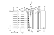
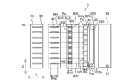
- FIG. 3 is a schematic diagram showing the configuration of each plate-like member 1p of the refrigerant distributor 1 according to the first embodiment.
- a plurality of plate-like members 1p stacked in the first direction (Z-axis direction) are shown laid out from the right side to the left side in the figure in order from the side to which the refrigerant inlet tube 2 is connected.
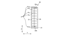
- FIG. 4 is a projection of the outward path Pu, the discharge hole 21, and a plurality of flat tube connecting passages Po onto the return path plate-like member 30 in FIG. 3.
- FIG. 5 is a cross-sectional view showing a schematic cross section A-A of the refrigerant distributor 1 in FIG. 2. Below, the structure of the refrigerant distributor 1 will be described in detail based on FIGS. 3 to 5 and with reference to FIG. 2.
- the refrigerant distributor 1 has a branched flow path P therein, and distributes the refrigerant flowing in from the inlet portion 11 to a plurality of flat tubes 5 (see FIG. 2) when the heat exchanger 100 (see FIG. 2) functions as an evaporator.
- the outline arrows F1, F2, and dashed arrow F3 in FIG. 3 indicate the flow direction of the refrigerant in each flow path portion in the refrigerant distributor 1.
- each of the multiple plate-shaped members 1p constituting the refrigerant distributor 1 is formed, for example, using a metal plate, and has a strip-like shape that is long in one direction.
- the longitudinal direction of the plate-shaped member 1p is the arrangement direction of the multiple flat tubes 5 (see FIG. 2) connected to the refrigerant distributor 1, that is, the vertical direction (Z-axis direction).
- the short side direction of the plate-shaped member 1p is a third direction (Y-axis direction) perpendicular to the vertical direction (Z-axis direction) which is the arrangement direction of the multiple flat tubes 5 (see FIG. 2) and the second direction (X-axis direction) which is the extension direction of the pipes of the flat tubes 5.
- the short side direction (Y-axis direction) of the plate-shaped member 1p is also the horizontal direction when the refrigerant distributor 1 is viewed from one side of the stacking direction (X-axis direction).
- the stacking direction of the multiple plate-shaped members 1p i.e., the second direction (X-axis direction)
- the plate thickness direction of the plate-shaped member 1p may be referred to as the plate thickness direction of the plate-shaped member 1p.
- the flow path P has an outgoing path Pu and a return path Pd that extend in the vertical direction (Z-axis direction), and an upper communication path Pca and a lower communication path Pcb that connect the outgoing path Pu and the return path Pd in an annular shape.
- An inlet 11 is connected to the lower end of the outgoing path Pu, and the refrigerant from the inlet 11 circulates through the outgoing path Pu, the upper communication path Pca, the return path Pd, and the lower communication path Pcb. In other words, the refrigerant flows upward in the outgoing path Pu and downward in the return path Pd.
- the flow path P also has multiple flat tube communication paths Po that individually connect the multiple flat tube insertion holes 51 to the return path Pd.
- the refrigerant distributor 1 of the first embodiment is composed of five plate-shaped members 1p. Adjacent members among the multiple plate-shaped members 1p are joined by brazing.
- both side surfaces in the stacking direction are composed of an inlet plate-shaped member 10 in which a refrigerant inlet 11 is formed, and an insertion side plate-shaped member 50 in which multiple flat tube insertion holes 51 are formed.
- an outward path plate-shaped member 20 in which an outward path Pu is formed a return path plate-shaped member 30 in which a return path Pd is formed, and a communication path plate-shaped member 40 in which multiple flat tube communication paths Po are formed are arranged.
- an upper communication path Pca and a lower communication path Pcb are formed in the return path plate-shaped member 30.
- the refrigerant inlet 11 is, for example, a circular hole penetrating the inlet plate member 10 in the plate thickness direction (X-axis direction), and the end of the refrigerant inlet pipe 2 is inserted into the inlet 11.
- the inlet 11 is provided at the lower end of the inlet plate member 10.
- the outgoing path Pu is, for example, a rectangular hole 22 penetrating the outgoing path plate member 20 in the plate thickness direction (X-axis direction). Below the outgoing path Pu in the outgoing plate member 20, a discharge hole 21 connected to the outgoing path Pu is provided opposite the inlet 11 of the inlet plate member 10.
- the width of the connection between the hole 22 and the discharge hole 21 constituting the outgoing path Pu in the outgoing plate member 20 is smaller than the width Wu of the outgoing path Pu and the width of the discharge hole 21, and the refrigerant flowing in from the inlet 11 is blown out into the outgoing path Pu through the discharge hole 21.
- the width of each flow path section refers to the length of each flow path section in the horizontal direction (i.e., the short side direction (Y-axis direction) of the plate-shaped member 1p).
- the return path Pd is, for example, a rectangular hole 31 that penetrates the return path plate member 30 in the plate thickness direction (X-axis direction).
- the return path Pd and the outgoing path Pu are arranged approximately parallel to each other so as not to overlap each other when viewed in the stacking direction (X-axis direction) and spaced apart in the short direction (Y-axis direction).
- the width Wd of the return path Pd is approximately the same width as the width Wu of the outgoing path Pu.
- the upper communication passage Pca is, for example, a rectangular hole 32a that penetrates the return path plate member 30 in the plate thickness direction (X-axis direction), and is a flow path portion that communicates the upper end of the return path Pd with the upper end of the outgoing path Pu in the stacking direction (X-axis direction).
- the upper communication passage Pca extends from the upper end of the return path Pd to the side of the outgoing path Pu (right side in the figure) in the short direction (Y-axis direction) and is provided so as to overlap with the upper end of the outgoing path Pu.
- the lower communication passage Pcb is, for example, a rectangular hole 32b that penetrates the return path plate member 30 in the plate thickness direction (X-axis direction), and is a flow path portion that communicates the lower end of the return path Pd with the lower end of the outgoing path Pu in the stacking direction (X-axis direction).
- the lower communication passage Pcb extends from the lower end of the return path Pd to the side of the outgoing path Pu in the short direction (Y-axis direction) and is provided so as to overlap with the lower end of the outgoing path Pu.
- the lower communication passage Pcb is connected to the inside of the outward passage Pu above the discharge hole 21.
- the outgoing path Pu is formed to the right of the center in the short side direction (Y-axis direction) of the outgoing plate member 20 and the returning path Pd is formed to the left of the center in the short side direction (Y-axis direction) of the returning plate member 30.
- the discharge hole 21 is formed on the right side of the lower part of the outgoing plate member 20, and the inflow section 11 is formed on the right side of the lower part of the inflow section plate member 10 so as to face the discharge hole 21.
- the returning path Pd, the upper communication passage Pca, and the lower communication passage Pcb are formed in the returning plate member 30.
- the outgoing path Pu of the outgoing plate member 20 except for the part overlapping with the upper communication passage Pca and the lower communication passage Pcb in the stacking direction, as well as the entire discharge hole 21, are covered by the plate surface portion 35 of the returning plate member 30.
- the flat tube insertion holes 51 are spaced apart from one another in the vertical direction so as to correspond to the flat tubes 5.
- the flat tube insertion holes 51 are holes that penetrate the insertion side plate member 50 in the plate thickness direction (X-axis direction) and have the same shape as the cross-sectional shape of the flat tube 5 described above.
- the flat tube communication passage Po that connects the return path Pd and the flat tube insertion hole 51 is a hole 41 that penetrates the communication passage plate member 40 in the plate thickness direction (X-axis direction) and has, for example, approximately the same shape as the flat tube insertion hole 51.
- the width Wo of the flat tube communication passage Po that connects the return path Pd and the flat tube insertion hole 51 in the stacking direction (X-axis direction) is set to be equal to or greater than the width Wd of the return path Pd.
- the flat tube communication passage Po is a flow path portion that diffuses the refrigerant that flows out of the return path Pd in the short direction (Y-axis direction) and causes it to flow into the flat tube 5.
- the width Wo of the flat tube communicating passage Po may be constant or may vary in the plate thickness direction of the communicating passage plate member 40 (i.e., the stacking direction (X-axis direction) of the multiple plate-shaped members 1p), but is made greater than the width Wd of the return path Pd throughout the plate thickness direction (X-axis direction).
- the flat tube communicating passage Po does not have a flow path portion that is smaller than the width Wd of the return path Pd in the short direction (Y-axis direction) of the communicating passage plate member 40.
- the refrigerant is less likely to experience flow inertia in the stacking direction (X-axis direction) between the return path Pd and the flat tube insertion hole 51, making it easier for the refrigerant to diffuse laterally (Y-axis direction).
- the width Wo of the flat tube communication passage Po changes in the plate thickness direction (X-axis direction)
- it is preferable that the width Wo of the flat tube communication passage Po increases as it approaches the flat tube insertion hole 51.
- the width Wo of the flat tube communication passage Po is equal to or greater than the width Wd of the return path Pd, and is preferably equal to or greater than the width Wp of the pipe of the flat tube 5. If the flat tube 5 is a flat porous pipe having multiple pipe passages, the flat tube communication passage Po is provided so as to communicate with all of the pipe passages.
- the width Wo of the flat tube communication passage Po is made smaller than the width of the flat tube insertion hole 51 by the thickness of the tube wall of the flat tube 5.
- the width Wo of the flat tube communication passage Po slightly smaller than the width of the flat tube insertion hole 51, when the end 5a of the flat tube 5 is inserted into the flat tube insertion hole 51, the end face of the flat tube 5 comes into contact with the plate surface of the insertion side plate member 50 of the communication passage plate member 40 and stops. Therefore, the flat tube communication passage Po, which is the space in which the refrigerant diffuses between the return path Pd and the end face of the flat tube 5, can be easily secured, and a refrigerant distributor 1 with good manufacturability can be provided.
- the refrigerant distributor 1 may have any configuration as long as it has the above-mentioned flow path P, and the number of plate-like members 1p constituting the refrigerant distributor 1 may be, for example, six or more.
- the upper communication passage Pca and the lower communication passage Pcb may be configured to connect the outward path Pu and the return path Pd, and may be provided, for example, in the outward path plate-like member 20 of the outward path plate-like member 20 and the return path plate-like member 30.
- the upper communication passage Pca may be provided in one of the outward path plate-like member 20 and the return path plate-like member 30, and the lower communication passage Pcb may be provided in the other plate-like member.
- the upper communication passage Pca and the lower communication passage Pcb may be provided in both the outward path plate-like member 20 and the return path plate-like member 30, respectively, so as to penetrate these two plate-like members 1p.
- FIG. 6 is an exploded schematic diagram showing a modified example of the refrigerant distributor 1 of FIG. 3.
- the return path plate member 130 is configured such that, of the outward path Pu, the return path Pd, the upper communicating path Pca, and the lower communicating path Pcb that constitute the circulation path, only the return path Pd is formed.
- the upper communicating path Pca and the lower communicating path Pcb are formed in the outward path plate member 120.
- the operation of the refrigerant distributor 1 according to the first embodiment will be described with reference to Figs. 1 to 3 and 5, taking as an example the operation when the heat exchanger 100 (see Fig. 2) functions as an evaporator of the refrigeration cycle device 200.
- the outdoor heat exchanger 105 functions as an evaporator.
- the refrigerant flowing into the refrigerant distributor 1 of the outdoor heat exchanger 105 is a gas-liquid two-phase flow.
- the gas-liquid two-phase refrigerant flows from the refrigerant inlet pipe 2 (see FIG. 2) into the flow path P of the refrigerant distributor 1.
- the gas-liquid two-phase refrigerant that flows into the flow path P is discharged upward into the outgoing path Pu through the discharge hole 21 having a discharge mechanism formed at the bottom of the outgoing path plate member 20, and flows upward in the outgoing path Pu in the extension direction of the outgoing path Pu and reaches the upper end of the outgoing path Pu as indicated by the white arrow F1.
- the gas-liquid two-phase refrigerant When the gas-liquid two-phase refrigerant reaches the upper end of the outgoing path Pu, it flows horizontally from the outgoing path Pu toward the upper connecting passage Pca formed in the return path plate member 30, and flows into the upper end of the return path Pd through the upper connecting passage Pca.
- the gas-liquid two-phase refrigerant that flows into the upper end of the return path Pd flows downward in the return path Pd along the direction of gravity as indicated by the white arrow F2.
- the gas-liquid two-phase refrigerant flowing downward in the return path Pd descends, it branches off and flows into multiple flat tube communication passages Po formed in the communication passage plate member 40 adjacent to the return path plate member 30, as indicated by the dashed arrows.
- the gas-liquid two-phase refrigerant that flows into each flat tube communication passage Po from the return path Pd flows into the pipe of the flat tube 5 inserted in the flat tube insertion hole 51 that communicates with that flat tube communication passage Po.
- the width Wo of the flat tube communication passage Po which is the flow path portion that communicates the return path Pd and the flat tube 5 is set to be greater than or equal to the width Wd of the return path Pd in the plate thickness direction (X-axis direction) of the communication passage plate member 40, as described above. Therefore, in the present disclosure, there is no flow path portion between the return path Pd and the end face of the flat tube 5 that is narrower than the width Wd of the return path Pd, so compared to the conventional case, the gas-liquid two-phase refrigerant that flows out of the return path Pd is less likely to have flow inertia in the stacking direction (X-axis direction).
- the gas-liquid two-phase refrigerant can be made to flow more uniformly in the horizontal direction in each flat tube 5 than in the conventional case, and the heat exchange performance of the heat exchanger 100 can be improved.
- the refrigerant distributor 1 is formed by stacking a plurality of plate-like members 1p each extending in the vertical direction (Z-axis direction), has a plurality of flat tube insertion holes 51 formed in the vertical direction into which the ends 5a of the flat tubes 5 are inserted, and has a refrigerant inlet section 11 formed therein.
- the flow path P is formed internally and branches the refrigerant flowing in from the inlet section 11 to flow into the plurality of flat tubes 5.
- the flow path P has an outward path Pu that extends in the vertical direction and is connected to the inlet section 11 at its lower end so that the refrigerant flows upward, a return path Pd that extends in the vertical direction so that the refrigerant flows downward, and an upper communication path Pca and a lower communication path Pcb that annularly connect the outward path Pu and the return path Pd.
- the flow path P has multiple flat tube connection passages Po that individually connect the multiple flat tube insertion holes 51 to the return path Pd, and when the multiple plate-like members 1p are viewed in the stacking direction (X-axis direction), the width Wo of the flat tube connection passages Po is equal to or greater than the width Wd of the return path Pd across the stacking direction.
- the refrigerant distributor 1 includes an inlet plate member 10 in which a refrigerant inlet 11 is formed, and an insertion side plate member 50 in which a plurality of flat tube insertion holes 51 into which the ends 5a of the flat tubes 5 are inserted are formed in the vertical direction.
- the refrigerant distributor 1 is formed by stacking a plurality of plate members 1p each extending in the vertical direction, and the refrigerant flowing in from the inlet 11 is branched and flows into the plurality of flat tubes 5.
- the plurality of plate members 1p have an outward path Pu extending in the vertical direction, and an outward path plate member 20 provided adjacent to the inlet plate member 10 between the inlet plate member 10 and the insertion side plate member 50 so that the inlet 11 is connected to the lower end of the outward path Pu.
- the plurality of plate members 1p also have a return path Pd extending in the vertical direction, and a return path plate member 30 provided adjacent to the outward path plate member 20 between the outward path plate member 20 and the insertion side plate member 50.
- the plate members 1p also have a communication passage plate member 40 that is provided between the return path plate member 30 and the insertion side plate member 50 and adjacent to each of the return path plate member 30 and the insertion side plate member 50, and has a plurality of flat tube communication passages Po formed therein that individually connect the flat tube insertion holes 51 to the return path Pd.
- One or both of the outward path plate member 20 and the return path plate member 30 are formed with an upper communication passage Pca and a lower communication passage Pcb that connect the outward path Pu and the return path Pd in an annular shape.
- the width Wo of the flat tube communication passage Po is equal to or greater than the width Wd of the return path Pd in the stacking direction.
- the width Wo of each of the flat tube communication passages Po that individually connect the flat tube insertion holes 51 to the return path Pd is equal to or greater than the width Wd of the return path Pd in the stacking direction.
- the refrigerant is less likely to experience flow inertia in the stacking direction, and the refrigerant is more likely to diffuse in the horizontal direction (Y-axis direction) in the flat tube communication passages Po. Therefore, it is possible to provide a refrigerant distributor 1 that can cause the refrigerant to flow more uniformly in the horizontal direction (Y-axis direction) into the flat tubes 5 than conventional devices.
- the plurality of plate-shaped members 1p also include an outward path plate-shaped member 20 in which the outward path Pu is formed, and a return path plate-shaped member 30 in which the return path Pd is formed.
- the upper communication passage Pca and the lower communication passage Pcb are formed in one or both of the outward path plate-shaped member 20 and the return path plate-shaped member 30, respectively.
- the outward path Pu and the return path Pd are provided in different plate-shaped members.
- the width of the portion separating the outward path Pu and the return path Pd (the lateral distance between the outward path Pu and the return path Pd shown in FIG.
- the return path plate member 30 is formed with only the return path Pd, one of the upper communication path Pca and the lower communication path Pcb and only the return path Pd, or both the upper communication path Pca and the lower communication path Pcb and only the return path Pd.
- the return path Pd is formed in the return path plate member 30, and multiple small holes that form part of the flow path P are provided in the return path plate member 30.
- the width Wd of the return path Pd is limited in order to secure an area for providing multiple small holes in the return path plate member 30.
- the return path plate member 30 is configured so that only the return path Pd, the upper communication path Pca, and the lower communication path Pcb of the flow path P are provided, thereby improving the design freedom of the width Wd of the return path Pd.
- the multiple plate-shaped members 1p also include an insertion side plate-shaped member 50 in which multiple flat tube insertion holes 51 are formed, and a communication passage plate-shaped member 40 in which multiple flat tube communication passages Po are formed that communicate with the multiple flat tube insertion holes 51.
- the communication passage plate-shaped member 40 is disposed between the return path plate-shaped member 30 and the insertion side plate-shaped member 50 so as to be adjacent to each of the return path plate-shaped member 30 and the insertion side plate-shaped member 50.
- the heat exchanger 100 includes the above-mentioned refrigerant distributor 1 or 1a and a plurality of flat tubes 5 connected to the refrigerant distributor 1 or 1a. Because the heat exchanger 100 includes the above-mentioned refrigerant distributor 1 or 1a, the gas-liquid two-phase refrigerant can flow more uniformly in the horizontal direction (Y-axis direction) in each flat tube 5 than in the past, improving the heat exchange performance.
- Embodiment 2. 7 is a schematic development view showing the configuration of each plate-shaped member 1p of the refrigerant distributor 1b according to the second embodiment.
- the same reference numerals are used for components having the same functions and actions as those of the first embodiment, and the description thereof is omitted.
- the relationship between the width Wd of the return path Pd and the width Wu of the forward path Pu is different from that in the first embodiment.
- the outgoing path Pu extends in the longitudinal direction (Z-axis direction) of the outgoing plate member 220
- the returning path Pd extends in the longitudinal direction (Z-axis direction) of the returning plate member 230.
- the returning path Pd and the outgoing path Pu are arranged approximately parallel to each other and spaced apart in the short direction (Y-axis direction) so as not to overlap each other when viewed in the stacking direction (X-axis direction).
- the width Wd of the return path Pd is approximately the same as the width Wu of the forward path Pu, but in the refrigerant distributor 1b of the second embodiment, the width Wd of the return path Pd is different from the width Wu of the forward path Pu.
- the width Wu of the forward path Pu is narrower and the width Wd of the return path Pd is wider, so that the width Wd of the return path Pd, where the refrigerant flows downward, is wider than the width Wu of the forward path Pu, where the refrigerant flows upward.
- the width of the plate surface portion 235 on the right side of the return path Pd in the return path plate member 30 is narrower than the width of the plate surface portion 35 (see FIG. 3) in the refrigerant distributor 1 of the first embodiment.
- the width Wu of the outgoing path Pu and the width Wd of the return path Pd are different sizes.
- the refrigerant becomes easier to circulate, improving the distribution performance of the refrigerant to the multiple flat tubes 5.
- FIG. 8 is an exploded schematic diagram showing a modified example of the refrigerant distributor 1b in FIG. 7.
- the return path Pd and the outgoing path Pu are spaced apart in the short direction (Y-axis direction) so as not to overlap each other when viewed in the stacking direction (X-axis direction).
- the hole 322 formed in the outgoing path plate member 320 that constitutes the outgoing path Pu has a constant width Wu in the vertical direction (Z-axis direction).
- the hole 331 formed in the return path plate member 330 that constitutes the return path Pd is configured so that the width Wd changes in the vertical direction (Z-axis direction).
- the edge of the hole 331 that constitutes the return path Pd on the outgoing path Pu side is inclined so that the width Wd1 of the return path Pd gradually increases from the bottom end to the top end of the return path Pd. Therefore, the separation distance in the short direction (Y-axis direction) between the return path Pd and the outgoing path Pu decreases from the bottom end to the top end of the return path Pd.
- the width Wd1 of the upper end of the return path Pd is greater than the width Wd2 of the lower end of the return path Pd.
- Fig. 9 is a schematic development view showing the configuration of each plate-like member 1p of the refrigerant distributor 1d according to the third embodiment.
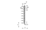
- Fig. 10 is a vertical cross-sectional view showing the flow path P in the refrigerant distributor 1d of Fig. 9.
- the refrigerant flow in the stacking direction is indicated by dashed arrows. Note that components having the same functions and actions as those in the first embodiment are given the same reference numerals and their description is omitted.
- the refrigerant distributor 1d according to the third embodiment differs from the refrigerant distributor 1 according to the first embodiment in that the flow path P has a return path extension portion 424 that further extends the return path Pd.
- the return path extension portion 424 extends the return path Pd in the stacking direction (X-axis direction). As shown in FIG. 9, the return path extension portion 424 is formed in the outgoing plate member 420 arranged adjacent to the return path plate member 30 in which the return path Pd is formed.
- the return path extension portion 424 is, for example, a rectangular hole penetrating the outgoing plate member 420 in the plate thickness direction (X-axis direction).
- the return path extension portion 424 may be a recess formed in the plate surface of the outgoing plate member 420 on the return path plate member 30 side.
- the volume of the return path extension portion 424 can be made constant depending on the plate thickness of the outgoing plate member 420, and can be made the same as the design dimension regardless of the insertion variation of the multiple flat tubes 5.
- the outgoing plate member 420 has a plurality of return extensions 424 formed thereon, which are arranged in the vertical direction (Z-axis direction) in the projection region R of the return path Pd when the plate members 1p are viewed in the stacking direction (X-axis direction).
- the number of return extensions 424 formed on the outgoing plate member 420 may be one.
- the width of each return extension 424 is approximately the same as the width Wd of the return path Pd.
- an upper communication passage Pca is provided across the outward path plate member 420 and the return path plate member 30 in the stacking direction (X-axis direction).
- the outward path plate member 420 has, for example, a rectangular hole 423a extending from the upper end of the outward path Pu to the return path Pd side (left side in the figure) in the short direction (Y-axis direction).
- this hole 423a is provided so as to overlap with the upper end of the return path Pd provided in the return path plate member 30 and the hole 32a extending from the upper end of the return path Pd.
- the upper communication passage Pca is formed by the hole 423a of the outward path plate member 420 and the hole 32a of the return path plate member 30.
- each return path extension 424 is provided in a region lower than the upper communication passage Pca in the projection region R of the return path Pd. Also, in FIG. 9, each return path extension 424 is formed between two adjacent flat tube insertion holes 51 in the projection region R of the return path Pd.
- the gas-liquid two-phase refrigerant that flows into the flow path P of the refrigerant distributor 1d rises in the forward path Pu, then flows into the return path Pd via the upper connecting path Pca and descends.
- the dashed arrow in FIG. 10 while the gas-liquid two-phase refrigerant descends toward the lower end of the return path Pd, a portion of the liquid refrigerant, particularly the liquid refrigerant flowing along the wall surface, flows into and stagnates in the return path expansion section 424. This reduces the amount of liquid refrigerant that stagnates at the lower end of the return path Pd, and prevents the refrigerant from flowing unevenly into the flat tubes 5 at the bottom. As a result, the refrigerant is more easily distributed evenly to the flat tubes 5 arranged in the vertical direction, improving the heat exchange performance of the heat exchanger 100.
- the location of the return extension section 424 in the refrigerant distributor 1d is not limited to the above. Two modified examples are described below.
- FIG. 11 is a schematic development view showing a first modified example of the refrigerant distributor 1d of FIG. 9.
- FIG. 12 is a vertical cross-sectional view showing a flow path P in the refrigerant distributor 1e of FIG. 11.
- a plurality of return path extensions 424 are provided in the outward path plate member 420, and a plurality of return path extensions 442 are also provided in the communication path plate member 440 arranged on the opposite side of the return path plate member 30 from the outward path plate member 420.
- the configuration of the outward path plate member 420 is the same as that of the refrigerant distributor 1d shown in FIG. 9, so a description thereof will be omitted here.
- the return path extension portion 442 is, for example, a rectangular hole that penetrates the communication path plate member 440 in the plate thickness direction (X-axis direction).
- the multiple return path extension portions 442 are formed in positions facing the multiple return path extension portions 424 of the outward path plate member 420.
- the return path extension portion 442 may be a recess formed in the plate surface of the communication path plate member 440 on the side of the return path plate member 30.
- a plurality of return path extensions 424 are provided in the up-down direction on the forward path plate member 420, and a plurality of return path extensions 442 are provided in the up-down direction on the flat tube communication passage Po. Therefore, as shown in FIG. 12, the gas-liquid two-phase refrigerant descending in the return path Pd alternately passes through the first space S1 having a width in the stacking direction (X-axis direction) the same as the plate thickness of the return path plate member 30, and the second space S2 formed by the return path Pd being expanded on both sides in the stacking direction by the return path extensions 442 and the return path extensions 424.
- the refrigerant distributor 1e of the first modified example when the gas-liquid two-phase refrigerant passes through the second space S2, a portion of the liquid refrigerant flows into the return path extensions 424 and 442 and stagnates there. Therefore, compared to the configuration of FIG. 9, in which the return path Pd is expanded in only one direction in the stacking direction, the refrigerant distributor 1e of the first modified example can further reduce the amount of liquid refrigerant remaining at the lower end of the return path Pd, improving the refrigerant distribution performance.
- FIG. 13 is a schematic development view showing a second modified example of the refrigerant distributor 1d of FIG. 9.
- FIG. 14 is a vertical cross-sectional view showing a flow path P in the refrigerant distributor 1f of FIG. 13.
- the multiple return path extensions 424 are provided between two adjacent flat tube insertion holes 51 in the projection region R of the return path Pd.
- the multiple return path extensions 524 are provided at positions that overlap at least a portion of the multiple flat tube insertion holes 51 in the projection region R of the return path Pd when the multiple plate-shaped members 1p are viewed in the stacking direction (X-axis direction).
- the upper communication passage Pca is provided only in the return path plate-shaped member 30 out of the outward path plate-shaped member 520 and the return path plate-shaped member 30.
- the multiple return path extension portions 524 are formed in positions that overlap with at least a portion of the multiple flat tube insertion holes 51 in the projection region R of the return path Pd when the multiple plate-like members 1p are viewed in the stacking direction (X-axis direction).
- each flat tube 5 the stagnant liquid refrigerant and the end portion 5a of each flat tube 5 are in the same position in the vertical direction (Z-axis direction), making it easier for the liquid refrigerant to flow out of the refrigerant distributor 1 through each flat tube 5.
- the amount of liquid refrigerant stagnating at the lower end of the return path Pd can be further reduced.
- FIG. 15 is a vertical cross-sectional view showing a schematic cross section of the refrigerant distributor 1d of FIG. 9 along the line B-B.
- the relationship between the cross-sectional area Sc1 of the upper communication passage Pca and the cross-sectional area Sc2 of the lower communication passage Pcb will be described below with reference to FIG. 9 and FIG. 15.
- the cross-sectional area Sc1 of the upper communication passage Pca is larger than the cross-sectional area Sc2 of the lower communication passage Pcb so that the refrigerant can easily flow from the forward path Pu to the return path Pd in the flow path P shown in FIG. 9.
- FIG. 9 the example of FIG.
- the upper communication passage Pca and the lower communication passage Pcb have the same length in the vertical direction (Z-axis direction).
- the length of the upper communication passage Pca in the stacking direction (X-axis direction) is longer than the length of the lower communication passage Pcb in the stacking direction (X-axis direction) by the thickness of the forward path plate-shaped member 420, so the cross-sectional area Sc1 of the upper communication passage Pca is larger than the cross-sectional area Sc2 of the lower communication passage Pcb.
- the flow path cross-sectional areas Sc1 and Sc2 can be adjusted by the vertical (Z-axis) lengths of the upper communication passage Pca and the lower communication passage Pcb.
- FIG. 16 is a schematic diagram showing an example of a configuration in which the return path extensions 524 provided discretely in the refrigerant distributor 1f of FIG. 13 are provided as a single unit.
- the return path extension 524a is, for example, a rectangular hole that penetrates the forward path plate member 520 in the plate thickness direction (X-axis direction) and extends in the longitudinal direction (Z-axis direction).
- the return path extension 524a and the forward path Pu are provided approximately parallel to each other and spaced apart in the short direction (Y-axis direction).
- the return path extension sections 424 provided discretely on the forward path plate member 420 may be integrated to provide a single return path extension section.
- the flow path P has one return path extension section 524a extending in the vertical direction, or multiple return path extension sections 424 arranged in the vertical direction, which extend the return path Pd in the stacking direction, in the projection area R of the return path Pd when the multiple plate-like members 1p are viewed in the stacking direction (X-axis direction).
- the refrigerant distributor 1d makes it less likely for the refrigerant to stagnate at the lower end of the return path Pd. This makes it easier to evenly distribute and cool the refrigerant to the multiple flat tubes 5, and applying the refrigerant distributor 1d to the heat exchanger 100 improves heat exchange performance.
- the flow path cross-sectional area Sc1 of the upper communication passage Pca is larger than the flow path cross-sectional area Sc2 of the lower communication passage Pcb. This makes it easier for the refrigerant discharged from the discharge hole 21 to the lower end of the return path Pd to flow upward through the outward path Pu and then to flow into the return path Pd via the upper communication passage Pca, suppressing backflow in the circulation path. Suppressing backflow in the circulation path promotes the circulation of the refrigerant and also promotes the inflow of the refrigerant into each flat tube 5.
- Embodiment 4. 17 is a schematic development view showing the configuration of each plate-like member 1p of a refrigerant distributor 1g according to embodiment 4. Note that components having the same functions and actions as those in embodiment 1 are given the same reference numerals and their description is omitted.
- the refrigerant distributor 1g according to embodiment 4 differs from the refrigerant distributor 1g according to embodiment 1 in that the flat tube communication passage Po connecting the return path Pd and the flat tube insertion hole 51 is provided across multiple plate-like members 1p.
- the flow path P has a refrigerant circulation path consisting of an outward path Pu, a return path Pd, an upper communication path Pca, and a lower communication path Pcb, and a number of flat tube communication paths Po that individually connect the multiple flat tube insertion holes 51 to the return path Pd.
- the refrigerant distributor 1g of the fourth embodiment is composed of seven plate-shaped members 1p. These seven plate-shaped members 1p are fastened to each other by fasteners (not shown). For this reason, mounting holes h1 and h2 for inserting fasteners are formed in two diagonal locations, for example, at the upper end and lower end of each plate-shaped member 1p. Note that multiple plate-shaped members 1p may be integrated by joining adjacent members of the multiple plate-shaped members 1p by brazing, without using fasteners.
- the refrigerant distributor 1g has two side surfaces in the stacking direction (X-axis direction) that are made up of an inlet plate member 610 in which the refrigerant inlet 11 is formed, and an insertion side plate member 650 in which multiple flat tube insertion holes 51 are formed. Between the inlet plate member 610 and the insertion side plate member 650, in order from the inlet plate member 610 side in the stacking direction, there are arranged an outward path plate member 620 in which an outward path Pu is formed, a return path plate member 630 in which a return path Pd is formed, and a communication path plate member group 640 in which multiple flat tube communication paths Po that communicate with the multiple flat tube insertion holes 51 are formed.
- the return path plate member 630 is also formed with an upper communication passage Pca and a lower communication passage Pcb.
- the upper communication passage Pca is a hole 32a that penetrates the return path plate member 630 in the plate thickness direction (X-axis direction) and is a flow path that connects the upper end of the return path Pd to the upper end of the outgoing path Pu in the stacking direction (X-axis direction).
- the lower communication passage Pcb is a hole 632b that penetrates the return path plate member 630 in the plate thickness direction (X-axis direction) and is a flow path that connects the lower end of the return path Pd to the lower end of the outgoing path Pu in the stacking direction (X-axis direction).
- the lower communication passage Pcb in the first embodiment extends linearly from the lower end of the return path Pd toward the outgoing path Pu in the short side direction (Y axis direction), but the lower communication passage Pcb in the fourth embodiment has a shape including a crank portion C when viewed in the stacking direction (X axis direction).
- the lower communication passage Pcb in the fourth embodiment is composed of a first extension portion Pcb1 extending in the short side direction (Y axis direction) from the return path Pd to approach the outgoing path Pu, a second extension portion Pcb2 extending upward from the end of the first extension portion Pcb1 on the outgoing path Pu side, and a third extension portion Pcb3 extending in the short side direction (Y axis direction) from the upper end of the second extension portion Pcb2 to approach the outgoing path Pu again, and has an approximately Z-shaped shape when viewed in the stacking direction (X axis direction).
- the outward plate member 620 is formed with a return path extension portion 624 that extends the return path Pd in the stacking direction (X-axis direction).
- the return path extension portion 624 is, for example, a rectangular hole that penetrates the outward plate member 620 in the plate thickness direction (X-axis direction).
- the outward plate member 620 is formed with a plurality of return path extension portions 624.
- the plurality of return path extension portions 624 are arranged in the vertical direction (Z-axis direction) in the projection region R of the return path Pd when the plurality of plate members 1p are viewed in the stacking direction (X-axis direction).
- Each return path extension portion 624 is provided between two adjacent flat tube insertion holes 51 in the vertical direction (Z-axis direction).
- each of the flat tube communication passages Po has a width Wo that changes in the stacking direction (X-axis direction). Therefore, the flat tube communication passage Po has a first communication passage portion Po1 having a width Wo1 and a second communication passage portion Po2 having a width Wo2 larger than the width Wo1 of the first communication passage portion Po1.
- the first communication passage portion Po1 communicates the return path Pd with the second communication passage portion Po2, and the second communication passage portion Po2 communicates the first communication passage portion Po1 with the flat tube insertion hole 51.
- the width Wo of the flat tube communication passage Po changes in the stacking direction (X-axis direction), but as in the first embodiment, the width Wo of the flat tube communication passage Po is equal to or greater than the width Wd of the return path Pd in the plate thickness direction (X-axis direction).
- first communication path plate member 640a adjacent to the return path plate member 630, and two second communication path plate members 640b and 640c arranged between the first communication path plate member 640a and the insertion side plate member 650. Between the return path plate member 630 and the insertion side plate member 650, the first communication path plate member 640a, the second communication path plate member 640b, and the second communication path plate member 640c are arranged in this order from the return path plate member 630 side.
- the second communication path plate member 640b is adjacent to the first communication path plate member 640a
- the second communication path plate member 640c is adjacent to each of the second communication path plate member 640b and the insertion side plate member 50.
- the first communication passage plate member 640a adjacent to the return path plate member 630 has a first communication passage portion Po1 in the multiple flat tube communication passages Po.
- the two multiple second communication passage plate members 640b and 640c have a second communication passage portion Po2 in the multiple flat tube communication passages Po.
- the first communication passage portion Po1 is, for example, a rectangular hole 643 that penetrates the first communication passage plate member 640a in the plate thickness direction (X-axis direction), and the first communication passage plate member 640a has multiple holes 643 in the vertical direction (Z-axis direction) so as to face the multiple flat tube insertion holes 51.
- the second communication passage portion Po2 is holes 641b and 641c that penetrate the two second communication passage plate members 640b and 640c in the plate thickness direction (X-axis direction), and has, for example, approximately the same shape as the flat tube insertion hole 51.
- Each of the second communication passage plate members 640b and 640c has multiple holes 641b or 641c in the vertical direction (Z-axis direction) that face the multiple flat tube insertion holes 51.
- the group of communication passage plate members 640 that constitute the flat tube communication passage Po is not limited to the above configuration.
- one of the two second communication passage plate members 640c may be omitted, and the flat tube communication passage Po may be constituted by the hole 643 of the first communication passage plate member 640a and the hole 641b of the second communication passage plate member 640b.
- the configuration of the lower communication passage Pcb is not limited to the above configuration. Modified examples are shown below.
- FIG 18 is an exploded schematic diagram showing a modified example of the refrigerant distributor 1g of Figure 17.
- the lower communication passage Pcb is composed of two parts: an outward path plate member 720 and a return path plate member 730.
- the lower communication passage Pcb is formed by connecting a hole 723b formed in the outward path plate member 720 and a hole 732b formed in the return path plate member 730.
- the hole 723b of the outward path plate member 720 extends in a straight line from the outward path Pu to the return path Pd in the short direction (Y-axis direction).
- the hole 732b formed in the return path plate member 730 extends from the return path Pd to the outward path Pu in the short direction (Y-axis direction) and then extends upward to form an inverted L-shape.
- the upper end of the hole 732b of the return path plate member 730 is provided to overlap the end of the hole 723b of the forward path plate member 720 on the return path Pd side, and the hole 732b of the return path plate member 730 and the hole 723b of the forward path plate member 720 are connected.
- the lower communication passage Pcb has an approximately Z-shaped shape when viewed in the stacking direction (X-axis direction).
- the crank portion C of the lower communication passage Pcb is formed in the return path plate member 730, and the remaining linear portion of the lower communication passage Pcb is formed in the forward path plate member 720.
- the shape of the lower communication passage Pcb is not limited to the above shape.
- the lower communication passage Pcb may be formed only by the crank portion C and have an inverted L-shape.
- the lower communication passage Pcb has a crank portion C composed of a first extension portion Pcb1 extending in the horizontal direction (Y-axis direction) from the return path Pd to approach the outgoing path Pu, and a second extension portion Pcb2 extending upward from the end of the first extension portion Pcb1 on the outgoing path Pu side.
- the resistance to the refrigerant that tries to flow back through the circulation passage from the lower end of the outgoing path Pu to the lower end of the return path Pd is increased, and the backflow can be suppressed. Therefore, the refrigerant that flows into the lower end of the outgoing path Pu from the discharge hole 21 is suppressed from flowing directly through the lower communication passage Pcb to the lower end of the return path Pd, and the outflow of the refrigerant biased to the lowest flat tube 5 is suppressed, improving the distribution performance.
- each of the multiple flat tube connecting passages Po is composed of a first connecting passage portion Po1 connected to the return path Pd, and a second connecting passage portion Po2 connected to the flat tube insertion hole 51 and having a width Wo2 larger than the width Wo1 of the first connecting passage portion Po1 when viewed in the stacking direction.
- the multiple plate-shaped members 1p include an insertion side plate-shaped member 650 in which multiple flat tube insertion holes 51 are formed, a first communication passage plate-shaped member 640a that is arranged between the return path plate-shaped member 630 and the insertion side plate-shaped member 650 so as to be adjacent to the return path plate-shaped member 630 and in which a first communication passage portion Po1 in the multiple flat tube communication passages Po is formed, and a second communication passage plate-shaped member 640c that is arranged between the first communication passage plate-shaped member 640a and the insertion side plate-shaped member 650 so as to be adjacent to the insertion side plate-shaped member 650 and in which a second communication passage portion Po2 in the multiple flat tube communication passages Po is formed.
- the width Wo of the flat tube communication passage Po can be changed in the stacking direction (X-axis direction), improving the freedom of design.
- Fig. 19 is a schematic development view showing the configuration of each plate-like member 1p of the refrigerant distributor 1i according to the fifth embodiment.
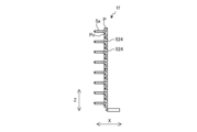
- Fig. 20 is a vertical cross-sectional view showing the flow path P in the refrigerant distributor 1i of Fig. 19.
- Fig. 21 is a horizontal cross-sectional view showing a cross section of the refrigerant distributor 1i of Fig. 19, which passes through the first communication passage portion Po1. Note that components having the same functions and actions as those of the first embodiment are given the same reference numerals and their description is omitted.
- the refrigerant distributor 1i according to the fifth embodiment differs from the refrigerant distributor 1 according to the first embodiment in that a part of the return path Pd is formed in the first plate-like member 820 in which the outward path Pu is formed.
- the flow path P has a refrigerant circulation path consisting of an outgoing path Pu, a return path Pd, an upper communication path Pca, and a lower communication path Pcb, and a plurality of flat tube communication paths Po that individually connect the plurality of flat tube insertion holes 51 to the return path Pd.
- the return path Pd was configured to extend in the vertical direction (Z-axis direction) in a flat plate shape, but as shown in FIG. 20, the return path Pd in embodiment 5 is configured to extend in the vertical direction (Z-axis direction) while meandering in the stacking direction (X-axis direction).
- each of the flat tube communication passages Po has a width Wo that changes in the stacking direction (X-axis direction). Therefore, the flat tube communication passage Po has a first communication passage portion Po1 having a width Wo1 and a second communication passage portion Po2 having a width Wo2 larger than the width Wo1 of the first communication passage portion Po1.
- the first communication passage portion Po1 communicates the return path Pd with the second communication passage portion Po2, and the second communication passage portion Po2 communicates the first communication passage portion Po1 with the flat tube insertion hole 51.
- the width Wo of the flat tube communication passage Po changes in the stacking direction (X-axis direction), but as in the first embodiment, the width Wo of the flat tube communication passage Po is equal to or larger than the width Wd of the return path Pd in the plate thickness direction (X-axis direction).
- the refrigerant distributor 1i of the fifth embodiment is composed of five plate-shaped members 1p. Adjacent members among the multiple plate-shaped members 1p are joined by brazing.
- both side surfaces in the stacking direction are composed of an inlet plate member 10 in which a refrigerant inlet 11 is formed, and an insertion side plate member 50 in which a plurality of flat tube insertion holes 51 are formed in the up-down direction (Z-axis direction).
- a first plate member 820, a second plate member 830, and a third plate member 840 are arranged in this order in the stacking direction from the side of the inlet plate member 10.
- the first plate-like member 820 is provided with most of the circulation paths, such as part of the return path Pd, the outward path Pu, the upper communication path Pca, and the lower communication path Pcb.
- the first plate-like member 820 is formed with a plurality of first return path holes 825 that form part of the serpentine return path Pd, a hole 22 that forms the outward path Pu, a hole 823a that forms the upper communication path Pca, and a hole 823b that forms the lower communication path Pcb.
- the second plate-like member 830 is provided with the remaining portion of the return path Pd and a portion of each of the multiple flat tube communication passages Po.
- the second plate-like member 830 is formed with multiple second return path holes 831 that form the remaining portion of the serpentine return path Pd, and multiple holes 832 that form the first communication passage portions Po1 in the multiple flat tube communication passages Po.
- each of the flat tube communication passages Po are provided in the third plate-shaped member 840. More specifically, the third plate-shaped member 840 has a plurality of holes 41 formed therein that constitute the second communication passage portions Po2 of the flat tube communication passages Po.
- the second return holes 831 are spaced apart in the vertical direction of the second plate-shaped member 830, and each of the second return holes 831 connects two adjacent first return holes 825 in the vertical direction (Z-axis direction) of the first plate-shaped member 820.
- the first return holes 825 are spaced apart in the vertical direction of the first plate-shaped member 820, and each of the first return holes 825 connects two adjacent second return holes 831 in the vertical direction (Z-axis direction) of the second plate-shaped member 830.
- the refrigerant descending in the return path Pd collides with a portion 826 that separates the two adjacent first return holes 825 in the first plate-shaped member 820, and this portion 826 functions as a descending suppression plate for the refrigerant.
- the holes 832 constituting the first communication passage portion Po1 and the second return passage holes 831 are arranged alternately in the vertical direction (Z-axis direction) in the second plate-shaped member 830.
- the second plate-shaped member 830 also has a plate surface portion 835 that covers the outgoing passage Pu, the upper communication passage Pca, and the lower communication passage Pcb in the first plate-shaped member 820.
- each flow path section is not limited to the above.
- the shape of the return path Pd does not have to be serpentine.
- the descending suppression plate through which the refrigerant descends (the portion 826 that separates the two adjacent first return path holes 825 in the first plate-shaped member 820) only needs to be located in at least one location above or below the topmost flat tube 5.
- the refrigerant distributor 1i of the fifth embodiment includes an inlet plate member 10 in which the inlet 11 of the refrigerant is formed, and an insertion side plate member 50 in which a plurality of flat tube insertion holes 51 into which the ends 5a of the flat tubes 5 are inserted are formed in the vertical direction.
- the refrigerant distributor 1i is formed by stacking a plurality of plate members 1p each extending in the vertical direction, and the refrigerant flowing in from the inlet 11 is branched and flows into a plurality of flat tubes 5.
- the plurality of plate members 1p are formed with an outward path Pu extending in the vertical direction, and a part of a return path Pd extending in the vertical direction (Z-axis direction) while meandering in the stacking direction (X-axis direction), and has a first plate member 820 provided adjacent to the inlet plate member 10 between the inlet plate member 10 and the insertion side plate member 50 so that the inlet 11 is connected to the lower end of the outward path Pu.
- the plate-shaped members 1p also have a second plate-shaped member 830 in which the remaining portion of the return path Pd is formed and which is provided adjacent to the first plate-shaped member 820 between the first plate-shaped member 820 and the insertion side plate-shaped member 50.
- the plate-shaped members 1p also have a third plate-shaped member 840 in which the second plate-shaped member 830 and the insertion side plate-shaped member 50 are provided adjacent to each of the second plate-shaped member 830 and the insertion side plate-shaped member 50 and in which at least a portion of each of the flat tube communication passages Po that individually communicate the flat tube insertion holes 51 with the return path Pd is formed.
- a third plate-shaped member 840 in which the second plate-shaped member 830 and the insertion side plate-shaped member 50 are provided adjacent to each of the second plate-shaped member 830 and the insertion side plate-shaped member 50 and in which at least a portion of each of the flat tube communication passages Po that individually communicate the flat tube insertion holes 51 with the return path Pd is formed.
- an upper communication passage Pca and a lower communication passage Pcb that annularly communicate the outward path Pu and the return path Pd are formed.
- the return path Pd extends in the vertical direction (Z-axis direction) while meandering in the stacking direction (X-axis direction).
- the plurality of plate-shaped members 1p includes an insertion side plate-shaped member 50 in which a plurality of flat tube insertion holes 51 are formed, and a first plate-shaped member 820 in which a plurality of first return path holes 825 and an outward path Pu that constitute a part of the return path Pd are formed.
- the plurality of plate-shaped members 1p also includes a second plate-shaped member 830 disposed between the first plate-shaped member 820 and the insertion side plate-shaped member 50 so as to be adjacent to the first plate-shaped member 820.
- the second plate-shaped member 830 has a plurality of second return path holes 831 that constitute the remaining part of the return path Pd.
- the plurality of plate-shaped members 1p also includes a third plate-shaped member 840 disposed between the second plate-shaped member 830 and the insertion side plate-shaped member 50 so as to be adjacent to each of the second plate-shaped member 830 and the insertion side plate-shaped member 50. At least a portion of each of the flat tube communication passages Po is formed in the third plate member 840.
- the upper communication passage Pca and the lower communication passage Pcb are formed in the first plate member 820 or the second plate member 830.
- the second return holes 831 are provided in the vertical direction (Z-axis direction) of the second plate member 830, and each of them connects two first return holes 825 adjacent to each other in the vertical direction of the first plate member 820.
- the second plate member 830 has a plate surface portion 835 that covers the outward passage Pu, the upper communication passage Pca, and the lower communication passage Pcb in the first plate member 820.
- the return path Pd has a curved shape, so the gas-liquid two-phase refrigerant is agitated in the return path Pd, compared to the configuration in the first embodiment in which the return path Pd is flat.
- the refrigerant distribution in the vertical direction in the return path Pd is made uniform, improving distribution performance.
- Each of the flat tube communication passages Po is composed of a first communication passage portion Po1 connected to the return path Pd, and a second communication passage portion Po2 connected to the flat tube insertion hole 51 and having a width Wo2 larger than the width Wo1 of the first communication passage portion Po1 when viewed in the stacking direction (X-axis direction).
- the first communication passage portion Po1 of the flat tube communication passages Po is formed in the second plate-shaped member 830.
- the second communication passage portion Po2 of the flat tube communication passages Po is formed in the third plate-shaped member 840.
- the first communication passage portion Po1 and the second return path hole 831 are arranged alternately in the vertical direction in the second plate-shaped member 830.
- the width Wo of the flat tube communication passage Po can be changed in the stacking direction (X-axis direction), improving the freedom of design.
Landscapes
- Engineering & Computer Science (AREA)
- Physics & Mathematics (AREA)
- Mechanical Engineering (AREA)
- Thermal Sciences (AREA)
- General Engineering & Computer Science (AREA)
- Heat-Exchange Devices With Radiators And Conduit Assemblies (AREA)
Priority Applications (4)
| Application Number | Priority Date | Filing Date | Title |
|---|---|---|---|
| CN202380091760.5A CN120548449A (zh) | 2023-01-25 | 2023-01-25 | 制冷剂分配器和热交换器 |
| DE112023005676.5T DE112023005676T5 (de) | 2023-01-25 | 2023-01-25 | Kältemittel-verteiler und wärmetauscher |
| PCT/JP2023/002189 WO2024157369A1 (ja) | 2023-01-25 | 2023-01-25 | 冷媒分配器及び熱交換器 |
| JP2024572580A JP7805488B2 (ja) | 2023-01-25 | 2023-01-25 | 冷媒分配器及び熱交換器 |
Applications Claiming Priority (1)
| Application Number | Priority Date | Filing Date | Title |
|---|---|---|---|
| PCT/JP2023/002189 WO2024157369A1 (ja) | 2023-01-25 | 2023-01-25 | 冷媒分配器及び熱交換器 |
Publications (1)
| Publication Number | Publication Date |
|---|---|
| WO2024157369A1 true WO2024157369A1 (ja) | 2024-08-02 |
Family
ID=91969991
Family Applications (1)
| Application Number | Title | Priority Date | Filing Date |
|---|---|---|---|
| PCT/JP2023/002189 Ceased WO2024157369A1 (ja) | 2023-01-25 | 2023-01-25 | 冷媒分配器及び熱交換器 |
Country Status (4)
| Country | Link |
|---|---|
| JP (1) | JP7805488B2 (https=) |
| CN (1) | CN120548449A (https=) |
| DE (1) | DE112023005676T5 (https=) |
| WO (1) | WO2024157369A1 (https=) |
Citations (6)
| Publication number | Priority date | Publication date | Assignee | Title |
|---|---|---|---|---|
| JP2005513403A (ja) * | 2001-12-21 | 2005-05-12 | ベール ゲーエムベーハー ウント コー カーゲー | 特に自動車用の熱交換器 |
| JP2009150574A (ja) * | 2007-12-19 | 2009-07-09 | Mitsubishi Electric Corp | 分配器、およびそれを搭載した熱交換器並びに空気調和機 |
| WO2015049727A1 (ja) * | 2013-10-01 | 2015-04-09 | 三菱電機株式会社 | 積層型ヘッダー、熱交換器、及び、空気調和装置 |
| WO2015063875A1 (ja) * | 2013-10-30 | 2015-05-07 | 三菱電機株式会社 | 積層型ヘッダー、熱交換器、及び、空気調和装置 |
| JP2020051632A (ja) * | 2018-09-21 | 2020-04-02 | 日立ジョンソンコントロールズ空調株式会社 | 熱交換器、及び、これを備える空気調和機 |
| WO2021149223A1 (ja) * | 2020-01-23 | 2021-07-29 | 三菱電機株式会社 | 熱交換器及び冷凍サイクル装置 |
Family Cites Families (1)
| Publication number | Priority date | Publication date | Assignee | Title |
|---|---|---|---|---|
| CN114127488B (zh) | 2019-06-28 | 2023-01-13 | 大金工业株式会社 | 热交换器和热泵装置 |
-
2023
- 2023-01-25 JP JP2024572580A patent/JP7805488B2/ja active Active
- 2023-01-25 DE DE112023005676.5T patent/DE112023005676T5/de active Pending
- 2023-01-25 CN CN202380091760.5A patent/CN120548449A/zh active Pending
- 2023-01-25 WO PCT/JP2023/002189 patent/WO2024157369A1/ja not_active Ceased
Patent Citations (6)
| Publication number | Priority date | Publication date | Assignee | Title |
|---|---|---|---|---|
| JP2005513403A (ja) * | 2001-12-21 | 2005-05-12 | ベール ゲーエムベーハー ウント コー カーゲー | 特に自動車用の熱交換器 |
| JP2009150574A (ja) * | 2007-12-19 | 2009-07-09 | Mitsubishi Electric Corp | 分配器、およびそれを搭載した熱交換器並びに空気調和機 |
| WO2015049727A1 (ja) * | 2013-10-01 | 2015-04-09 | 三菱電機株式会社 | 積層型ヘッダー、熱交換器、及び、空気調和装置 |
| WO2015063875A1 (ja) * | 2013-10-30 | 2015-05-07 | 三菱電機株式会社 | 積層型ヘッダー、熱交換器、及び、空気調和装置 |
| JP2020051632A (ja) * | 2018-09-21 | 2020-04-02 | 日立ジョンソンコントロールズ空調株式会社 | 熱交換器、及び、これを備える空気調和機 |
| WO2021149223A1 (ja) * | 2020-01-23 | 2021-07-29 | 三菱電機株式会社 | 熱交換器及び冷凍サイクル装置 |
Also Published As
| Publication number | Publication date |
|---|---|
| CN120548449A (zh) | 2025-08-26 |
| JPWO2024157369A1 (https=) | 2024-08-02 |
| JP7805488B2 (ja) | 2026-01-23 |
| DE112023005676T5 (de) | 2025-11-13 |
Similar Documents
| Publication | Publication Date | Title |
|---|---|---|
| EP3370000B1 (en) | Outdoor unit for air conditioner | |
| JP6012857B2 (ja) | 積層型ヘッダー、熱交換器、及び、空気調和装置 | |
| JP6038302B2 (ja) | 積層型ヘッダー、熱交換器、及び、空気調和装置 | |
| US20030188857A1 (en) | Heat exchanger for exchanging heat between internal fluid and external fluid and manufacturing method thereof | |
| JP6138264B2 (ja) | 積層型ヘッダー、熱交換器、及び、空気調和装置 | |
| TWI768340B (zh) | 熱交換器及冷凍循環裝置 | |
| CN115111939B (zh) | 热交换器、室外机以及制冷循环装置 | |
| WO2014184914A1 (ja) | 積層型ヘッダー、熱交換器、及び、空気調和装置 | |
| WO2014184917A1 (ja) | 積層型ヘッダー、熱交換器、及び、空気調和装置 | |
| CN115298507A (zh) | 换热器 | |
| CN111902683B (zh) | 热交换器及制冷循环装置 | |
| JP7805488B2 (ja) | 冷媒分配器及び熱交換器 | |
| CN113739454A (zh) | 热交换器 | |
| JP2022043207A (ja) | 熱交換器、室外機、及び冷凍サイクル装置 | |
| JP2020085267A (ja) | 熱交換器 | |
| JP7799178B2 (ja) | 熱交換器および空気調和装置 | |
| JP2020112274A (ja) | 熱交換器 | |
| JP7493585B2 (ja) | 熱交換器、熱交換器ユニット及び冷凍サイクル装置 | |
| JP7209821B2 (ja) | 熱交換器及び冷凍サイクル装置 | |
| CN117545970A (zh) | 制冷循环装置 | |
| JP7496832B2 (ja) | 熱交換器、熱交換器ユニット、冷凍サイクル装置、及び熱交換部材の製造方法 | |
| JP7756851B1 (ja) | 冷凍サイクル装置 | |
| JP7678359B2 (ja) | 熱交換器及び冷凍サイクル装置 | |
| JP2025154120A (ja) | 熱交換器 | |
| JP2025163892A (ja) | 熱交換器および熱交換器を備えた冷凍サイクル装置 |
Legal Events
| Date | Code | Title | Description |
|---|---|---|---|
| 121 | Ep: the epo has been informed by wipo that ep was designated in this application |
Ref document number: 23918336 Country of ref document: EP Kind code of ref document: A1 |
|
| WWE | Wipo information: entry into national phase |
Ref document number: 2024572580 Country of ref document: JP |
|
| WWE | Wipo information: entry into national phase |
Ref document number: 202380091760.5 Country of ref document: CN |
|
| WWE | Wipo information: entry into national phase |
Ref document number: 112023005676 Country of ref document: DE |
|
| WWP | Wipo information: published in national office |
Ref document number: 202380091760.5 Country of ref document: CN |
|
| 122 | Ep: pct application non-entry in european phase |
Ref document number: 23918336 Country of ref document: EP Kind code of ref document: A1 |