WO2024154403A1 - 巻線切替装置及び巻線切替システム - Google Patents
巻線切替装置及び巻線切替システム Download PDFInfo
- Publication number
- WO2024154403A1 WO2024154403A1 PCT/JP2023/038740 JP2023038740W WO2024154403A1 WO 2024154403 A1 WO2024154403 A1 WO 2024154403A1 JP 2023038740 W JP2023038740 W JP 2023038740W WO 2024154403 A1 WO2024154403 A1 WO 2024154403A1
- Authority
- WO
- WIPO (PCT)
- Prior art keywords
- connection state
- windings
- winding
- abnormal heat
- heat generation
- Prior art date
- Legal status (The legal status is an assumption and is not a legal conclusion. Google has not performed a legal analysis and makes no representation as to the accuracy of the status listed.)
- Ceased
Links
Images





Classifications
-
- B—PERFORMING OPERATIONS; TRANSPORTING
- B60—VEHICLES IN GENERAL
- B60L—PROPULSION OF ELECTRICALLY-PROPELLED VEHICLES; SUPPLYING ELECTRIC POWER FOR AUXILIARY EQUIPMENT OF ELECTRICALLY-PROPELLED VEHICLES; ELECTRODYNAMIC BRAKE SYSTEMS FOR VEHICLES IN GENERAL; MAGNETIC SUSPENSION OR LEVITATION FOR VEHICLES; MONITORING OPERATING VARIABLES OF ELECTRICALLY-PROPELLED VEHICLES; ELECTRIC SAFETY DEVICES FOR ELECTRICALLY-PROPELLED VEHICLES
- B60L3/00—Electric devices on electrically-propelled vehicles for safety purposes; Monitoring operating variables, e.g. speed, deceleration or energy consumption
-
- B—PERFORMING OPERATIONS; TRANSPORTING
- B60—VEHICLES IN GENERAL
- B60L—PROPULSION OF ELECTRICALLY-PROPELLED VEHICLES; SUPPLYING ELECTRIC POWER FOR AUXILIARY EQUIPMENT OF ELECTRICALLY-PROPELLED VEHICLES; ELECTRODYNAMIC BRAKE SYSTEMS FOR VEHICLES IN GENERAL; MAGNETIC SUSPENSION OR LEVITATION FOR VEHICLES; MONITORING OPERATING VARIABLES OF ELECTRICALLY-PROPELLED VEHICLES; ELECTRIC SAFETY DEVICES FOR ELECTRICALLY-PROPELLED VEHICLES
- B60L9/00—Electric propulsion with power supply external to the vehicle
- B60L9/16—Electric propulsion with power supply external to the vehicle using AC induction motors
- B60L9/18—Electric propulsion with power supply external to the vehicle using AC induction motors fed from DC supply lines
-
- H—ELECTRICITY
- H02—GENERATION; CONVERSION OR DISTRIBUTION OF ELECTRIC POWER
- H02P—CONTROL OR REGULATION OF ELECTRIC MOTORS, ELECTRIC GENERATORS OR DYNAMO-ELECTRIC CONVERTERS; CONTROLLING TRANSFORMERS, REACTORS OR CHOKE COILS
- H02P25/00—Arrangements or methods for the control of AC motors characterised by the kind of AC motor or by structural details
- H02P25/16—Arrangements or methods for the control of AC motors characterised by the kind of AC motor or by structural details characterised by the circuit arrangement or by the kind of wiring
- H02P25/18—Arrangements or methods for the control of AC motors characterised by the kind of AC motor or by structural details characterised by the circuit arrangement or by the kind of wiring with arrangements for switching the windings, e.g. with mechanical switches or relays
Definitions
- This disclosure relates to a winding switching device and a winding switching system.
- This application claims priority to Japanese Application No. 2023-004338, filed on January 16, 2023, and incorporates by reference all of the contents of said Japanese application.
- some motors installed in electric vehicles can switch between a low-speed, high-torque operating state and a high-speed, low-torque operating state by switching the connections of multiple windings.
- Patent Document 1 discloses a device that estimates the temperature of the windings.
- a winding switching device is a winding switching device that switches the connection states of multiple windings included in a motor, and includes a switching unit that switches the connection states of the multiple windings, and a control unit that causes the switching unit to switch the connection state of the multiple windings from a first connection state to a second connection state in which a smaller current flows through the windings than in the first connection state, based on a detection value from a sensor that detects a physical quantity related to heat generated by the windings.
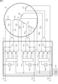
- FIG. 1 is a diagram illustrating an example of the configuration of a winding switching system according to the first embodiment.
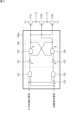
- FIG. 2 is a circuit diagram illustrating an example of the configuration of a connection switching unit according to the first embodiment.
- FIG. 3 is a circuit diagram showing an example of the configuration of the control circuit.
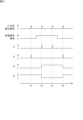
- FIG. 4 is a timing chart showing an example of transition of states of signals in the connection switching unit according to the first embodiment.
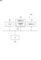
- FIG. 5 is a block diagram illustrating an example of a hardware configuration of the processing unit.
- FIG. 6 is a functional block diagram showing an example of the function of the winding switching device according to the first embodiment.
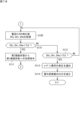
- FIG. 7A is the first half of a flowchart illustrating an example of switching control processing of the winding switching device according to the first embodiment.
- FIG. 7B is the second half of the flowchart showing an example of the switching control process of the winding switching device according to the first embodiment.
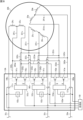
- FIG. 8 is a circuit diagram showing an example of the configuration of a winding switching device according to the second embodiment.
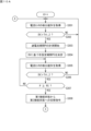
- FIG. 9 is a flowchart showing an example of a switching control process of the winding switching device according to the third embodiment.
- FIG. 10A is the first half of a flowchart illustrating an example of switching control processing of the winding switching device according to the fourth embodiment.
- FIG. 10B is the second half of the flowchart showing an example of the switching control process of the winding switching device according to the fourth embodiment.
- the winding switching device is a winding switching device that switches the connection states of multiple windings included in a motor, and includes a switching unit that switches the connection states of the multiple windings, and a control unit that causes the switching unit to switch the connection state of the multiple windings from a first connection state to a second connection state in which a smaller current flows through the windings than in the first connection state, based on a detection value from a sensor that detects a physical quantity related to heat generated by the windings. This makes it possible to change the current flowing through the windings depending on the state of heat generation in the windings, thereby suppressing heat generation.
- the winding switching device may further include a determination unit that determines whether abnormal heat generation will occur during operation of the motor based on a detection value of a sensor that detects a physical quantity related to heat generation by the windings, and the control unit may cause the switching unit to switch the connection state of the multiple windings from the first connection state to the second connection state when the determination unit determines that abnormal heat generation will occur.
- the control unit may cause the switching unit to switch the connection state of the multiple windings from the first connection state to the second connection state when the determination unit determines that abnormal heat generation will occur.
- the determination unit may determine whether or not abnormal heat generation has occurred based on a comparison between the detection value of the sensor and a first threshold value. In this way, by setting a first threshold value related to the occurrence of abnormal heat generation, it is possible to accurately determine whether or not abnormal heat generation has occurred.
- the sensor may be a current sensor that detects the current flowing through the winding, and the determination unit may determine that the abnormal heating has occurred when the period during which the detection value of the current sensor exceeds the first threshold is equal to or longer than a set period. This allows the occurrence of abnormal heating to be accurately determined using the detection value of the current flowing through the winding.
- a determination unit may be further provided that determines the set period based on the detection value of the current sensor.
- the amount of heat generated in the winding varies depending on the amount of current flowing through the winding. Therefore, by determining an appropriate set period depending on the detection value of the current flowing through the winding, it is possible to accurately determine whether abnormal heat has occurred.
- the sensor may be a temperature sensor that detects the temperature around the winding switching device. This makes it possible to accurately determine the occurrence of abnormal heat generation using the detected temperature around the winding switching device.
- the determination unit may determine whether the abnormal heat generation that has occurred has been eliminated based on the detection value of the sensor, and when the determination unit determines that the abnormal heat generation that has occurred has been eliminated, the control unit may cause the switching unit to switch the connection state of the multiple windings from the second connection state to the first connection state. This makes it possible to determine whether the abnormal heat generation has been eliminated, and when it is determined that the abnormal heat generation has been eliminated, the connection state of the windings may be restored to the first connection state in which a large current flows through the windings.
- the determination unit may determine that the abnormal heat generation has been resolved when the detection value of the sensor falls below a second threshold. This allows accurate determination of the elimination of the abnormal heat generation by setting a second threshold related to the elimination of the abnormal heat generation.
- the determination unit determines whether or not a second abnormal heat generation having a temperature equal to or higher than the abnormal heat generation has occurred based on the detection value of the sensor, and the winding switching device may further include a notification unit that notifies a user of the occurrence of an abnormality when the determination unit determines that the second abnormal heat generation has occurred. This makes it possible to determine the occurrence of a more serious second abnormal heat generation.
- the occurrence of the abnormality is notified to the user, allowing the user to take action to resolve the abnormality.
- control unit may reduce the current supplied to the winding when the determination unit determines that the second abnormal heat generation has occurred. In this way, when the second abnormal heat generation occurs, the current flowing through the winding can be reduced to suppress heat generation.
- the winding switching device may further include a detection unit that detects a zero-cross point of a measurement value of a current sensor that measures a current flowing through the winding, and the switching unit may switch the connection state of the multiple windings between the first connection state and the second connection state based on a result of detection of the zero-cross point by the detection unit. This makes it possible to suppress the occurrence of a surge voltage when switching the connection of the windings.
- the winding switching system includes a motor capable of switching the connection state of multiple windings, a power converter that converts DC power output from a battery into AC power and supplies the AC power to the motor, and a winding switching device for switching the connection state of the multiple windings, the winding switching device including a switching unit that switches the connection state of the multiple windings, and a control unit that causes the switching unit to switch the connection state of the multiple windings from a first connection state to a second connection state in which a smaller current flows through the windings than in the first connection state based on a detection value of a sensor that detects a physical quantity related to heat generated by the windings.
- the present disclosure can be realized not only as a winding switching device having the characteristic configuration described above, but also as a winding switching method that includes steps of characteristic processing in a winding switching device, or as a winding switching system that includes a winding switching device.
- FIG. 1 is a diagram illustrating an example of the configuration of a winding switching system according to the first embodiment.
- the winding switching system 10 is mounted on a vehicle (hereinafter referred to as an "electric vehicle") that is propelled by a motor, such as an electric vehicle or a plug-in hybrid vehicle.
- the winding switching system 10 includes a motor 20, a power converter 30, a battery 40, and a winding switching device 100.
- the motor 20 is a driving motor that generates propulsive force for the electric vehicle.
- the motor 20 is driven by three-phase AC power.
- One example of the motor 20 is a permanent magnet synchronous motor.
- the battery 40 is a battery that supplies power to drive the motor 20.
- the battery 40 is a secondary battery, for example a lithium ion battery.
- the power converter 30 is an inverter that converts DC power supplied from the battery 40 into three-phase AC power.
- the power converter 30 may also have the function of converting the three-phase AC power output when the motor 20 functions as a generator into DC power and charging the battery 40.
- the power converter 30 includes legs for the U, V, and W phases.
- the U-phase leg includes switches 31u and 32u
- the V-phase leg includes switches 31v and 32v
- the W-phase leg includes switches 31w and 32w.
- the switches 31u, 32u, 31v, 32v, 31w, and 32w perform switching to convert DC power into three-phase AC power.
- the switches 31u, 32u, 31v, 32v, 31w, and 32w are, for example, IGBTs (Insulated Gate Bipolar Transistors) or power MOSFETs (Metal Oxide Semiconductor Field-Effect Transistors).
- Power line 35u corresponding to U phase extends from the U phase leg
- power line 35v corresponding to V phase extends from the V phase leg
- power line 35w corresponding to W phase extends from the W phase leg.
- current sensor 33u is provided on power line 35u
- current sensor 33v is provided on power line 35v
- current sensor 33w is provided on power line 35w.
- Current sensor 33u detects the current value of current Iu of U phase.
- Current sensor 33v detects the current value of current Iv of V phase.
- Current sensor 33w detects the current value of current Iw of W phase.
- Current sensors 33u, 33v, 33w can detect the current values of currents Iu, Iv, Iw flowing through power lines 35u, 35v, 35w, including DC and AC components.
- the current sensors 33u, 33v, and 33w are, for example, DCCTs (direct current transformers) or shunt resistors.
- the winding switching device 100 is disposed between the motor 20 and the power converter 30. However, the position of the winding switching device 100 is not limited to between the motor 20 and the power converter 30.
- the power converter 30 and the winding switching device 100 are connected by power lines 35u, 35v, and 35w, and the winding switching device 100 and the motor 20 are connected by a plurality of power lines 25.
- the winding switching device 100 switches the connection state of the multiple windings of the motor 20. The configuration of the winding switching device 100 will be described later.
- the three-phase AC currents Iu, Iv, and Iw output from the power converter 30 are supplied to the motor 20 via the winding switching device 100.
- the winding switching device 100 includes a connection switching unit 110 and a processing unit 150 .
- FIG. 2 is a circuit diagram showing an example of the configuration of the connection switching unit according to the first embodiment.
- the motor 20 includes a plurality of windings 21u, 22u, 21v, 22v, 21w, and 22w.
- the windings 21u and 22u correspond to the U phase
- the windings 21v and 22v correspond to the V phase
- the windings 21w and 22w correspond to the W phase.
- the number of windings for each phase is not limited to two, and may be three or more.
- the windings 22u, 22v, and 22w are connected at the neutral point 23.
- the connection switching unit 110 switches the connection state of the windings 21u, 22u, 21v, 22v, 21w, and 22w for each phase between a series connection state and a parallel connection state.
- the connection switching unit 110 includes current sensors 101u, 101v, and 101w, zero-cross detection circuits 102u, 102v, and 102w, control circuits 103u, 103v, and 103w, and switching circuits 104u, 104v, and 104w.
- the zero-cross detection circuits 102u, 102v, and 102w detect the zero-cross point of the measurement value of the current sensors 101u, 101v, and 101w.
- the zero-cross detection circuits 102u, 102v, and 102w compare the output voltage from the current sensors 101u, 101v, and 101w with zero voltage, and detect the point in time when the output voltage from the current sensors 101u, 101v, and 101w matches the zero voltage as the zero-cross point.
- the zero voltage is an example of a reference voltage.
- the reference voltage is a voltage that corresponds to the output voltage of the current sensors 101u, 101v, and 101w when the current flowing through the windings 21u, 22u, 21v, 22v, 21w, and 22w becomes zero current, and is not limited to zero voltage.
- the zero-cross detection circuits 102u, 102v, and 102w are an example of a detection unit.
- the switching circuits 104u, 104v, and 104w switch the connection state of the windings 21u, 22u, 21v, 22v, 21w, and 22w between a series connection state and a parallel connection state when the zero-cross detection circuits 102u, 102v, and 102w detect a zero-cross point.
- the switching circuits 104u, 104v, and 104w are an example of a switching unit.
- connection switching unit 110 the connection switching unit 110, the power line 35u, and the motor 20 will be explained for the U phase.
- Power line 35u is connected to one end of winding 21u.
- Power line 212u extends from the other end of winding 21u.
- Power line 221u extends from one end of winding 22u, and power line 222u extends from the other end.
- the switching circuit 104u includes semiconductor relays 111u, 112u, and 113u.
- the semiconductor relays 111u, 112u, and 113u are, for example, IGBTs or power MOSFETs.
- the power line 35u is drawn into the connection switching unit 110. Inside the connection switching unit 110, the power line 35u branches off at a midpoint and is connected to a first terminal of a semiconductor relay 111u. The second terminal of the semiconductor relay 111u is connected to a first terminal of a semiconductor relay 112u. A power line 221u extending from the winding 22u is connected to the connection point between the second terminal of the semiconductor relay 111u and the first terminal of the semiconductor relay 112u.
- the second terminal of the semiconductor relay 112u is connected to the first terminal of the semiconductor relay 113u.
- a power line 212u extending from the winding 21u is connected to the connection point between the second terminal of the semiconductor relay 112u and the first terminal of the semiconductor relay 113u.
- a power line 222u extending from the winding 22u is connected to the second terminal of the semiconductor relay 113u.
- the windings 21u and 22u are connected in series.
- the semiconductor relays 111u and 113u are in the ON state and the semiconductor relay 112u is in the OFF state, the windings 21u and 22u are connected in parallel.
- a signal line extending from the control circuit 103u is connected to each of the gate terminals of the semiconductor relays 111u, 112u, and 113u.
- the power lines 212u, 221u, and 222u extend from the motor 20 and are drawn into the connection switching unit 110.
- a current sensor 101u is attached to the power line 221u.
- the current sensor 101u may be attached to the power lines 35u, 212u, or 222u instead of the power line 221u.
- the current sensor 101u detects the U-phase current flowing through the power line 221u.
- the current sensor 101u is, for example, an ACCT that detects only the AC component of the current.
- the signal line extending from the current sensor 101u is connected to the zero-cross detection circuit 102u.
- a signal line transmitting the output signal of the zero-cross detection circuit 102u (hereinafter referred to as the "zero-cross detection signal") extends from the zero-cross detection circuit 102u to the control circuit 103u.
- a signal line extending from the processing unit 150 is connected to the control circuit 103u.
- the zero-cross detection circuit 102u detects the zero-cross point of the measurement value by the current sensor 101u of the winding current flowing through the power line 221u.
- the zero-cross detection circuit 102u is a comparator.
- the inverting input of the comparator is set to a zero reference voltage, and the output signal of the current sensor 101u is applied to the non-inverting input.
- the output of the comparator changes from low to high at the point when the AC signal output from the current sensor 101u crosses the zero reference voltage (zero-cross point).
- FIG. 3 is a circuit diagram showing an example of the configuration of the control circuit 103u.
- the control circuit 103u includes AND circuits 131 and 133, a NOT circuit 132, and a latch circuit 120.
- a signal line extending from the zero-cross detection circuit 102u is connected to a first input terminal of the AND circuit 131 and a first input terminal of the AND circuit 133.
- a signal line extending from the processing unit 150 is connected to a second input terminal of the AND circuit 131.
- the signal line from the processing unit 150 is connected to an input terminal of the NOT circuit 132.
- a signal line extending from the output terminal of the NOT circuit 132 is connected to a second input terminal of the AND circuit 133.
- the latch circuit 120 is an RS flip-flop.
- the output terminal of the AND circuit 131 is connected to the input S (set) of the RS flip-flop 120.
- the output terminal of the AND circuit 133 is connected to the input R (reset) of the RS flip-flop 120.
- the RS flip-flop 120 includes two NOT circuits 121 and 123 and two NAND circuits 122 and 124. However, the RS flip-flop 120 may also be composed of two NOR circuits.
- the output Q of the RS flip-flop 120 is connected to the gates of the semiconductor relays 111u and 113u.
- the output Q bar of the RS flip-flop 120 is connected to the gate of the semiconductor relay 112u.
- connection switching control at zero crossing points Next, a description will be given of the connection switching control at the zero crossing point by the winding switching device 100. Note that the following description will be given mainly of the operation of switching the connection states of the windings 21u, 22u for the U phase. The same applies to the V and W phases, and therefore the description will be omitted.
- FIG. 4 is a timing chart showing an example of the transition of the states of the signals of the connection switching unit 110 according to the first embodiment.
- the current sensor 101u measures the winding current Iu flowing through the power line 221u.
- the zero-cross detection circuit 102u detects the zero-cross points of the measured value of the winding current Iu. That is, the zero-cross detection signal output from the zero-cross detection circuit 102u is low when the winding current Iu is not zero, and becomes high when the winding current Iu becomes zero. In FIG. 4, the zero-cross detection signal is low under normal conditions, and is high at times T1, T2, T3, and T4.
- the processing unit 150 sets the value of the switching command signal to Low when windings 21u, 22u, 21v, 22v, 21w, and 22w of the motor 20 are connected in series, and sets the value of the switching command signal to High when windings 21u, 22u, 21v, 22v, 21w, and 22w are connected in parallel.
- the switching command signal is Low in the initial state, and changes to High at a point between times T1 and T2.
- the switching command signal changes again to Low at a point between times T3 and T4.
- the zero-cross detection signal and the switching command signal are input to the AND circuit 131.
- the AND circuit 131 outputs Low when the zero-cross detection signal and the switching command signal are a combination of (Low, Low), (Low, High), and (High, Low).
- the AND circuit 131 outputs High when the zero-cross detection signal and the switching command signal are a combination of (High, High). That is, Low is normally input to S of the RS flip-flop 120, and High is input when a zero-cross point of the winding current Iu is detected and a parallel connection command for the windings 21u, 22u, 21v, 22v, 21w, and 22w is given.
- the input signal to S is High at times T2 and T3.
- the zero-cross detection signal and the inverted signal of the switching command signal are input to the AND circuit 133.
- the AND circuit 133 outputs Low when the zero-cross detection signal and the switching command signal are a combination of (Low, Low), (High, Low), and (High, High).
- the AND circuit 133 outputs High when the zero-cross detection signal and the switching command signal are a combination of (High, Low). That is, Low is normally input to R of the RS flip-flop 120, and High is input when a zero-cross point of the winding current Iu is detected and a command to connect the windings 21u, 22u, 21v, 22v, 21w, and 22w in series is given.
- the input signal of R is High at times T1 and T4.
- RS flip-flop 120 holds the previous output values of Q and Q-bar when inputs S and R are Low and Low. When inputs S and R are Low and High, RS flip-flop 120 outputs Q and Q-bar as Low and High, and when inputs S and R are High and Low, Q and Q-bar as High and Low. In RS flip-flop 120, the combination of High and High inputs S and R is prohibited.
- connection state of the windings 21u, 22u, 21v, 22v, 21w, and 22w can be switched between a series connection state and a parallel connection state at the timing of the zero-crossing points of the winding currents Iu, Iv, and Iw. This suppresses the occurrence of surge voltages. Furthermore, there is no need for complex processing to identify the period during which the winding currents Iu, Iv, and Iw are below a predetermined value, and the connection switching unit 110 can be configured without using a processor such as a CPU, FPGA, or ASIC.
- the processing unit 150 controls the power converter 30 and the connection switching unit 110. Specifically, signal lines extend from the processing unit 150 to each of the switches 31u, 32u, 31v, 32v, 31w, and 32w, and the processing unit 150 controls the on/off timing of the switches 31u, 32u, 31v, 32v, 31w, and 32w. A signal line extends from the processing unit 150 to the connection switching unit 110, and the processing unit 150 outputs a switching command signal to command the connection switching unit 110 to switch the connection state of the windings.
- FIG. 5 is a block diagram showing an example of the hardware configuration of the processing unit.
- the processing unit 150 includes a processor 151, a non-volatile memory 152, a volatile memory 153, and an interface (I/F) 154.
- I/F interface
- the volatile memory 153 is, for example, a semiconductor memory such as SRAM (Static Random Access Memory) or DRAM (Dynamic Random Access Memory).
- the non-volatile memory 152 is, for example, a flash memory, a hard disk, or a ROM (Read Only Memory).
- the non-volatile memory 152 stores a switching control program 155, which is a computer program, and data used to execute the switching control program 155. Each function of the processing unit 150 is exercised by the switching control program 155 being executed by the processor 151.
- the switching control program 155 can be stored in a recording medium such as a flash memory, a ROM, or a CD-ROM.
- the processor 151 controls the power converter 30 and the connection switching unit 110 using the switching control program 155.
- the processor 151 is, for example, a CPU (Central Processing Unit). However, the processor 151 is not limited to a CPU.
- the processor 151 may be a GPU (Graphics Processing Unit).
- the processor 151 is, for example, a multi-core processor.
- the processor 151 may be a single-core processor.
- the processor 151 may be, for example, an ASIC (Application Specific Integrated Circuit), or a programmable logic device such as a gate array or an FPGA (Field Programmable Gate Array). In this case, the ASIC or programmable logic device is configured to be capable of executing the same processing as the switching control program 155.
- ASIC Application Specific Integrated Circuit
- FPGA Field Programmable Gate Array
- the I/F 154 is connected to the switches 31u, 32u, 31v, 32v, 31w, and 32w of the power converter 30.
- the I/F 154 transmits on or off control signals to each of the switches 31u, 32u, 31v, 32v, 31w, and 32w.
- the I/F 154 is connected to the control circuits 103u, 103v, and 103w (see FIG. 2) of the connection switching unit 110.
- the I/F 154 transmits switching command signals to the control circuits 103u, 103v, and 103w.
- the I/F 154 is further connected to the current sensors 101u, 101v, and 101w (see FIG. 2).
- the I/F 154 receives the detection values output from the current sensors 101u, 101v, and 101w.
- the I/F 154 is connected to the display device 50 (see FIG. 1).
- the display device 50 includes, for example, a liquid crystal panel or an OEL (organic electroluminescence) panel.
- the display device 50 can display text or graphic information.
- the I/F 154 outputs a video signal to the display device 50 and controls the display on the display device 50.
- FIG. 6 Function of the winding switching device] 6 is a functional block diagram showing an example of functions of the winding switching device according to the first embodiment.
- the processor 151 executes the switching control program 155
- the winding switching device 100 executes the functions of an acquisition unit 161, a determination unit 162, a determination unit 163, a control unit 164, and a notification unit 165.
- Current sensor 101u detects the current flowing through windings 21u and 22u
- current sensor 101v detects the current flowing through windings 21v and 22v
- current sensor 101w detects the current flowing through windings 21w and 22w.
- Current sensors 101u, 101v, and 101w are examples of sensors that detect physical quantities related to heat generated by windings.
- Acquisition unit 161 acquires the current detection values from current sensors 101u, 101v, and 101w. Each of current sensors 101u, 101v, and 101w continuously detects a current value and continuously outputs the detected current value. Acquisition unit 161 acquires, for example, detection values from current sensors 101u, 101v, and 101w in chronological order.
- the determination unit 162 determines whether or not abnormal heat is generated in the motor 20 while the motor 20 is in operation based on the detection values of the current sensors 101u, 101v, and 101w.
- the windings 21u, 22u, 21v, 22v, 21w, and 22w generate heat depending on the current flowing through the windings 21u, 22u, 21v, 22v, 21w, and 22w. In other words, the greater the current flowing through the windings 21u, 22u, 21v, 22v, 21w, and 22w, the higher the temperatures of the windings 21u, 22u, 21v, 22v, 21w, and 22w. If the current flowing through the windings 21u, 22u, 21v, 22v, 21w, and 22w is excessive, the windings 21u, 22u, 21v, 22v, 21w, and 22w will generate abnormal heat. In this embodiment, the current flowing through the windings 21u, 22u, 21v, 22v, 21w, and 22w is used to determine whether abnormal heat generation will occur in the motor 20.
- the determination unit 162 determines that abnormal heat generation has occurred when the period P during which the detection values of the current sensors 101u, 101v, and 101w exceed the first threshold (hereinafter also referred to as the "overcurrent period P") is equal to or longer than the set period PS.
- the determination unit 162 compares the detection values of the current sensors 101u, 101v, and 101w with a first threshold value.
- the first threshold value is, for example, a current value corresponding to abnormal heat generation in the motor 20.
- the first threshold value may be a value lower than the current value corresponding to abnormal heat generation. This makes it possible to determine whether or not abnormal heat generation will occur before the abnormal heat generation actually occurs.
- the determination unit 162 can determine that abnormal heat generation has occurred when the period during which all detection values of the current sensors 101u, 101v, and 101w exceed the first threshold as the overcurrent period P, and determine that abnormal heat generation has occurred when the overcurrent period P is equal to or longer than the set period PS. In another example, the determination unit 162 can determine that abnormal heat generation has occurred when the period during which at least one detection value of the current sensors 101u, 101v, and 101w exceeds the first threshold as the overcurrent period P, and determine that abnormal heat generation has occurred when the overcurrent period P is equal to or longer than the set period PS.
- the determination unit 162 can determine that abnormal heat generation has occurred when the period during which at least two detection values of the current sensors 101u, 101v, and 101w exceed the first threshold as the overcurrent period P, and determine that abnormal heat generation has occurred when the overcurrent period P is equal to or longer than the set period PS.
- the determination unit 163 determines the set period PS based on the detection values of the current sensors 101u, 101v, and 101w. The higher the current flowing through the windings 21u, 22u, 21v, 22v, 21w, and 22w, the shorter the temperature will rise. In other words, there is a correlation between the current value flowing through the windings 21u, 22u, 21v, 22v, 21w, and 22w and the period until the windings 21u, 22u, 21v, 22v, 21w, and 22w reach a certain temperature.
- the determination unit 163 determines the set period PS that corresponds to the detection values of the current sensors 101u, 101v, and 101w according to a predetermined relationship between the current value and the set period PS. Specifically, the determination unit 163 shortens the set period PS as the detection values of the current sensors 101u, 101v, and 101w become higher, and lengthens the set period PS as the detection values of the current sensors 101u, 101v, and 101w become lower.
- the determination unit 163 determines the set period PS based on at least one of the detection values of the current sensors 101u, 101v, and 101w. For example, the determination unit 163 can determine the set period PS based on the average value of the detection values of the current sensors 101u, 101v, and 101w. In another example, the determination unit 163 can determine the set period PS based on the maximum value of the detection values of the current sensors 101u, 101v, and 101w. In yet another example, the determination unit 163 can determine the set period PS based on the minimum value of the detection values of the current sensors 101u, 101v, and 101w.
- the determination unit 163 can determine the set period PS corresponding to the detection values of the current sensors 101u, 101v, and 101w using a table that specifies the correspondence between the current value and the set period PS.
- the table is stored in advance in the non-volatile memory 152.
- the determination unit 163 can determine the set period PS corresponding to the detection values of the current sensors 101u, 101v, and 101w using a relational expression between the current value and the set period PS.
- the set period PS may be a fixed value. In this case, the determination unit 163 may be omitted.
- the control unit 164 causes the switching circuits 104u, 104v, and 104w to switch the connection state of the multiple windings 21u, 22u, 21v, 22v, 21w, and 22w from a parallel connection state to a series connection state.
- the control unit 164 switches the switching command signal output to the control circuits 103u, 103v, and 103w from High to Low when it is determined that abnormal heat generation will occur.
- the permanent magnet interlinkage magnetic flux is about twice as large as in the parallel connection state, and the armature current required to obtain the same torque output is about half. Therefore, the current flowing through the windings 21u, 22u, 21v, 22v, 21w, and 22w in the series connection state is smaller than the current flowing through the windings 21u, 22u, 21v, 22v, 21w, and 22w in the parallel connection state. Therefore, by switching the connection state of the windings 21u, 22u, 21v, 22v, 21w, and 22w from the parallel connection state to the series connection state, the temperature of the windings 21u, 22u, 21v, 22v, 21w, and 22w can be reduced.
- the parallel connection state is the "first connection state” and the series connection state is the "second connection state.”
- the determination unit 162 monitors the detection values of the current sensors 101u, 101v, and 101w. When the determination unit 162 determines that abnormal heat generation has occurred, it determines whether the abnormal heat generation has been resolved based on the detection values of the current sensors 101u, 101v, and 101w.
- the determination unit 162 determines that the abnormal heat generation has been resolved when the detection values of the current sensors 101u, 101v, and 101w fall below the second threshold.
- the determination unit 162 can determine that the abnormal heat generation has been resolved when all of the detection values of the current sensors 101u, 101v, and 101w fall below the second threshold.
- the determination unit 162 can determine that the abnormal heat generation has been resolved when at least one of the detection values of the current sensors 101u, 101v, and 101w falls below the second threshold.
- the determination unit 162 can determine that the abnormal heat generation has been resolved when at least two of the detection values of the current sensors 101u, 101v, and 101w fall below the second threshold.
- the second threshold is set to a value equal to or less than the first threshold. By setting the second threshold to a value smaller than the first threshold, it is possible to prevent abnormal heat generation from reoccurring shortly after the abnormal heat generation has been eliminated.
- the second threshold may be the same value as the first threshold.
- the control unit 164 causes the switching circuits 104u, 104v, and 104w to switch the connection state of the multiple windings 21u, 22u, 21v, 22v, 21w, and 22w from a series connection state to a parallel connection state.
- the control unit 164 determines that the abnormal heat generation has been eliminated, it switches the switching command signal output to the switching circuits 104u, 104v, and 104w from Low to High. This returns the connection state of the windings 21u, 22u, 21v, 22v, 21w, and 22w to a parallel connection state.
- the determination unit 162 determines whether or not a second abnormal heat generation has occurred at a temperature equal to or higher than the abnormal heat generation, based on the detection values of the current sensors 101u, 101v, and 101w.
- the determination unit 162 determines that the second abnormal heating has occurred when the detection values of the current sensors 101u, 101v, and 101w exceed the third threshold.
- the determination unit 162 can determine that the second abnormal heating has occurred when all the detection values of the current sensors 101u, 101v, and 101w exceed the third threshold.
- the determination unit 162 can determine that the second abnormal heating has occurred when at least one detection value of the current sensors 101u, 101v, and 101w exceeds the third threshold.
- the determination unit 162 can determine that the second abnormal heating has occurred when at least two detection values of the current sensors 101u, 101v, and 101w exceed the third threshold.
- the third threshold is set to a value equal to or greater than the first threshold.
- a second abnormal fever which is a temperature equal to or greater than the abnormal fever, can be accurately detected.
- the third threshold may be the same value as the first threshold.
- the notification unit 165 notifies the user of the occurrence of the abnormality.
- the notification unit 165 causes the display device 50 to display a screen for notifying the user of the occurrence of the abnormality.
- the control unit 164 When the determination unit 162 determines that the second abnormal heat generation has occurred, the control unit 164 reduces the current supplied to the windings 21u, 22u, 21v, 22v, 21w, and 22w. In other words, when the control unit 164 determines that the second abnormal heat generation has occurred, it controls the power converter 30 to reduce the output power from the power converter 30.
- FIGS. 7A and 7B are flowcharts showing an example of the switching control process of the winding switching device according to the first embodiment.
- the processor 151 acquires the detection values DVu, DVv, and DVw of the current sensors 101u, 101v, and 101w (step S101).
- the processor 151 compares each of the detection values DVu, DVv, and DVw with the first threshold value Th1 (step S102). If each of the detection values DVu, DVv, and DVw is equal to or less than the first threshold value Th1 (NO in step S102), the processor 151 returns to step S101.
- step S102 If each of the detection values DVu, DVv, and DVw exceeds the first threshold value Th1 (YES in step S102), the processor 151 starts measuring the overcurrent period P (step S103).
- the processor 151 determines the set period PS based on the detection values DVu, DVv, and DVw (step S104).
- the processor 151 acquires new detection values DVu, DVv, and DVw of the current sensors 101u, 101v, and 101w (step S105).
- the processor 151 compares each of the detection values DVu, DVv, and DVw with the first threshold value Th1 (step S106). If each of the detection values DVu, DVv, and DVw is equal to or less than the first threshold value Th1 (NO in step S106), the processor 151 returns to step S101.
- step S106 If each of the detection values DVu, DVv, and DVw exceeds the first threshold value Th1 (YES in step S106), the processor 151 compares the overcurrent period P with the set period PS (step S107).
- step S107 If the overcurrent period P is less than the set period PS (NO in step S107), the processor 151 returns to step S105.
- the processor 151 If the overcurrent period P is equal to or greater than the set period PS (YES in step S107), the processor 151 outputs a switching command signal to the control circuits 103u, 103v, and 103w to switch the connection state of the windings 21u, 22u, 21v, 22v, 21w, and 22w from the first connection state (parallel connection state) to the second connection state (series connection state) (step S108). This switches the connection state of the windings 21u, 22u, 21v, 22v, 21w, and 22w from the parallel connection state to the series connection state.
- the processor 151 acquires new detection values DVu, DVv, and DVw of the current sensors 101u, 101v, and 101w (step S109).
- the processor 151 compares each of the detection values DVu, DVv, and DVw with the second threshold value Th2 (step S110).
- step S110 If each of the detection values DVu, DVv, and DVw falls below the second threshold value Th2 (YES in step S110), the processor 151 outputs a switching command signal to the control circuits 103u, 103v, and 103w to switch the connection state of the windings 21u, 22u, 21v, 22v, 21w, and 22w from the second connection state (series connection state) to the first connection state (parallel connection state) (step S111). This switches the connection state of the windings 21u, 22u, 21v, 22v, 21w, and 22w from the series connection state to the parallel connection state. The processor 151 then returns to step S101.
- step S110 If each of the detection values DVu, DVv, and DVw is greater than or equal to the second threshold value Th2 (NO in step S110), the processor 151 compares each of the detection values DVu, DVv, and DVw with the third threshold value Th3 (step S112).
- step S112 If each of the detection values DVu, DVv, and DVw is less than or equal to the third threshold value Th3 (NO in step S112), the processor 151 returns to step S109.
- step S112 If each of the detection values DVu, DVv, and DVw exceeds the third threshold value Th3 (YES in step S112), the processor 151 displays an abnormality notification screen on the display device 50 and notifies the user of the occurrence of an abnormality (step S113). Furthermore, the processor 151 reduces the output power of the power converter 30 (step S114). This ends the switching control process.
- the winding switching device of the second embodiment switches the connection state of the multiple windings of a motor between a full connection state in which all of the multiple windings are connected, and a partial connection state in which some of the multiple windings are connected.
- FIG. 8 is a circuit diagram showing an example of the configuration of a winding switching device according to the second embodiment.
- Motor 20A includes a plurality of windings 24u, 25u, 24v, 25v, 24w, and 25w. Windings 24u and 25u correspond to the U phase, windings 24v and 25v correspond to the V phase, and windings 24w and 25w correspond to the W phase. However, the number of windings for each phase is not limited to two, and may be three or more.
- connection switching unit 110A switches the connection state of the windings 24u, 25u, 24v, 25v, 24w, and 25w for each phase between a fully connected state and a partially connected state.
- the connection switching unit 110A includes current sensors 131u, 131v, and 131w, zero-cross detection circuits 102u, 102v, and 102w, control circuits 103u, 103v, and 103w, and switching circuits 140u, 140v, and 140w.
- the zero-cross detection circuits 102u, 102v, and 102w detect the zero-cross points of the measured values of the current sensors 131u, 131v, and 131w.
- the configuration of the zero-cross detection circuits 102u, 102v, and 102w is the same as that of the first embodiment, so a description thereof will be omitted.
- the switching circuits 140u, 140v, and 140w switch the connection state of the windings 24u, 25u, 24v, 25v, 24w, and 25w between a fully connected state and a partially connected state when the zero-cross detection circuits 102u, 102v, and 102w detect a zero-cross point.
- the switching circuits 140u, 140v, and 140w are an example of a switching unit.
- Power line 35u is connected to one end of winding 24u.
- the other end of winding 24u and one end of winding 25u are connected to each other, and power line 241u extends from the midpoint between winding 24u and winding 25u.
- Power line 241u branches into power lines 242u and 243w.
- Power line 251u extends from the other end of winding 25u.
- Power line 251u branches into power lines 252u and 253w.
- Power line 35v is connected to one end of winding 24v.
- the other end of winding 24v and one end of winding 25v are connected to each other, and power line 241v extends from the midpoint between winding 24v and winding 25v.
- Power line 241v branches into power lines 242v and 243u.
- Power line 251v extends from the other end of winding 25v.
- Power line 251v branches into power lines 252v and 253u.
- Power line 35w is connected to one end of winding 24w.
- the other end of winding 24w and one end of winding 25w are connected to each other, and power line 241w extends from the midpoint between winding 24w and winding 25w.
- Power line 241w branches into power lines 242w and 243v.
- Power line 251w extends from the other end of winding 25w.
- Power line 251w branches into power lines 252w and 253v.
- the switching circuit 140u includes semiconductor relays 141u and 142u.
- the switching circuit 140v includes semiconductor relays 141v and 142v.
- the switching circuit 140w includes semiconductor relays 141w and 142w.
- the semiconductor relays 141u, 142u, 141v, 142v, 141w, and 142w are, for example, IGBTs or power MOSFETs.
- the first terminal of the semiconductor relay 141u is connected to the power line 242u, and the second terminal is connected to the power line 243u.
- the first terminal of the semiconductor relay 142u is connected to the power line 252u, and the second terminal is connected to the power line 253u.
- the connection relationship between the switching circuits 140v and 140w is the same as that of the switching circuit 140u, so a description is omitted.
- the power line 35u is drawn into the connection switching unit 110A.
- a current sensor 131u is attached to the power line 35u.
- the current sensor 131u detects the U-phase current flowing through the power line 35u.
- the current sensor 131u is, for example, an ACCT that detects only the AC component of the current.
- a signal line extending from the current sensor 131u is connected to the zero-cross detection circuit 102u. The same applies to the V-phase and W-phase.
- the output Q of the RS flip-flop 120 in the control circuit 103u is connected to the gate of the semiconductor relay 141u.
- the output Q bar of the RS flip-flop 120 is connected to the gate of the semiconductor relay 142u. The same is true for the V phase and the W phase.
- winding switching device 100A according to the second embodiment are similar to those of the winding switching device 100 according to the first embodiment, so the same components are given the same reference numerals and their description is omitted.
- the processing unit 150 sets the value of the switching command signal to Low when the windings 24u, 25u, 24v, 25v, 24w, and 25w of the motor 20 are to be fully connected, and sets the value of the switching command signal to High when the windings 24u, 25u, 24v, 25v, 24w, and 25w are to be partially connected.
- connection state of windings 21u, 22u, 21v, 22v, 21w, and 22w can be switched between a fully connected state and a partially connected state at the timing of the zero-crossing points of winding currents Iu, Iv, and Iw.
- the determination unit 162 determines whether or not abnormal heat is generated in the motor 20A while the motor 20A is operating, based on the detection values of the current sensors 131u, 131v, and 131w.
- the judgment unit 162 judges that abnormal heat generation has occurred when the overcurrent period P during which the detection values of the current sensors 131u, 131v, and 131w exceed the first threshold is equal to or longer than the set period PS.
- the decision unit 163 decides the set period PS based on the detection values of the current sensors 131u, 131v, and 131w.
- the control unit 164 when the determination unit 162 determines that abnormal heat generation will occur, the control unit 164 causes the switching circuits 140u, 140v, and 140w to switch the connection state of the multiple windings 24u, 25u, 24v, 25v, 24w, and 25w from a partial connection state to a full connection state. That is, when the connection state of the windings 24u, 25u, 24v, 25, 24w, and 25w is a partial connection state, the control unit 164 switches the switching command signal output to the control circuits 103u, 103v, and 103w from High to Low when it is determined that abnormal heat generation will occur.
- the partial connection state is the "first connection state”
- the full connection state is the "second connection state.”
- a temperature sensor 20T is disposed on the housing of the motor 20.
- the temperature sensor 20T detects the temperature around the motor 20.
- the temperature sensor 20T is an example of a sensor that detects a physical quantity related to heat generated by the windings.
- the temperature sensor 20T is connected to an I/F 154 (see FIG. 5) of the processing unit 150.
- the other configurations of the winding switching system according to the third embodiment are the same as those of the winding switching system according to the first embodiment, so the same components are given the same reference numerals and descriptions are omitted.
- the acquisition unit 161 acquires the temperature detection value by the temperature sensor 20T.
- the temperature sensor 20T continuously detects the temperature and continuously outputs the detected temperature.
- the acquisition unit 161 acquires, for example, the detection value from the temperature sensor 20T in chronological order.
- the determination unit 162 determines whether or not abnormal heat is generated in the motor 20 while the motor 20 is in operation based on the detection value of the temperature sensor 20T.
- the determination unit 162 compares the detection value of the temperature sensor 20T with a first threshold value.
- the first threshold value is, for example, a temperature value corresponding to abnormal heat generation of the motor 20.
- the first threshold value may be a value lower than the temperature value corresponding to abnormal heat generation. This makes it possible to determine whether or not abnormal heat generation will occur before the abnormal heat generation actually occurs.
- the judgment unit 162 does not use the set period PS to judge whether abnormal heat generation occurs. Therefore, the decision unit 163 can be omitted.
- the determination unit 162 determines whether the abnormal heat generation has been resolved based on the detection value of the temperature sensor 20T.
- the determination unit 162 determines that the abnormal heat generation has been resolved when the detection value of the temperature sensor 20T falls below the second threshold value.
- the second threshold is set to a value equal to or less than the first threshold. By setting the second threshold to a value smaller than the first threshold, it is possible to prevent abnormal heat generation from reoccurring shortly after the abnormal heat generation has been eliminated.
- the second threshold may be the same value as the first threshold.
- the determination unit 162 determines whether a second abnormal heat generation with a temperature equal to or higher than the abnormal heat generation has occurred based on the detection value of the temperature sensor 20T.
- the determination unit 162 determines that a second abnormal heat has occurred when the detection value of the temperature sensor 20T exceeds the third threshold value.
- the third threshold is set to a value equal to or greater than the first threshold.
- a second abnormal fever which is a temperature equal to or greater than the abnormal fever, can be accurately detected.
- the third threshold may be the same value as the first threshold.
- control unit 164 and the notification unit 165 are the same as those in the first embodiment, so the description will be omitted.
- FIG. 9 is a flowchart showing an example of the switching control process of the winding switching device according to the third embodiment.
- the processor 151 acquires the detection value DT of the temperature sensor 20T (step S201).
- the processor 151 compares each of the detection values DT with the first threshold TTh1 (step S202). If the detection value DT is equal to or less than the first threshold TTh1 (NO in step S202), the processor 151 returns to step S201.
- the processor 151 If the detection value DT exceeds the first threshold TTh1 (YES in step S202), the processor 151 outputs a switching command signal to the control circuits 103u, 103v, and 103w to switch the connection state of the windings 21u, 22u, 21v, 22v, 21w, and 22w from the first connection state (parallel connection state) to the second connection state (series connection state) (step S203). As a result, the connection state of the windings 21u, 22u, 21v, 22v, 21w, and 22w is switched from the parallel connection state to the series connection state.
- the processor 151 acquires a new detection value DT of the temperature sensor 20T (step S204).
- the processor 151 compares the detection value DT with the second threshold TTh2 (step S205).
- step S205 If the detection value DT is below the second threshold TTh2 (YES in step S205), the processor 151 outputs a switching command signal to the control circuits 103u, 103v, and 103w to switch the connection state of the windings 21u, 22u, 21v, 22v, 21w, and 22w from the second connection state (series connection state) to the first connection state (parallel connection state) (step S206). This switches the connection state of the windings 21u, 22u, 21v, 22v, 21w, and 22w from the series connection state to the parallel connection state. The processor 151 then returns to step S201.
- the processor 151 compares the detection value DT with the third threshold TTh3 (step S207).
- step S207 If the detection value DT is equal to or less than the third threshold TTh3 (NO in step S207), the processor 151 returns to step S204.
- the processor 151 causes the display device 50 to display an abnormality notification screen, and notifies the user of the occurrence of an abnormality (step S208). Furthermore, the processor 151 reduces the output power of the power converter 30 (step S209). This ends the switching control process.
- the connection state of the windings 21u, 22u, 21v, 22v, 21w, and 22w is switched from a parallel connection state to a series connection state.
- this is not limited to the above.
- the determination of abnormal heat generation based on the detection value of the temperature sensor 20T can also be applied to the second embodiment.
- connection state of the windings 24u, 25u, 24v, 25v, 24w, and 25w can also be switched from a partial connection state to a full connection state.
- a current sensor 33 is disposed on a power line connected to the battery 40.
- the current sensor 33 detects the output current of the battery 40.
- the output current of the battery 40 is supplied to the motor 20 via the power converter 30 and the connection switching unit 110.
- the current sensor 33 is an example of a sensor that detects a physical quantity related to heat generated by the windings.
- the current sensor 33 is connected to an I/F 154 (see FIG. 5) of the processing unit 150.
- the acquisition unit 161 acquires the current detection value by the current sensor 33.
- the current sensor 33 continuously detects the current value and continuously outputs the detected current value.
- the acquisition unit 161 acquires the detection value from the current sensor 33 in time series, for example.
- the determination unit 162 determines whether abnormal heat generation occurs in the battery 40 while the motor 20 is operating based on the detection value of the current sensor 33.
- the battery 40 When the battery 40 is over-discharged, it generates abnormal heat.
- the current output from the battery 40 is used to determine whether the battery 40 generates abnormal heat.
- the determination unit 162 determines that abnormal heat generation has occurred when the overcurrent period P during which the detection value of the current sensor 33 exceeds the first threshold is equal to or longer than the set period PS.
- the determination unit 162 compares the detection values of each of the current sensors 101u, 101v, and 101w with a first threshold value.
- the first threshold value is, for example, a current value corresponding to abnormal heat generation in the battery 40.
- the first threshold value may be a value lower than the current value corresponding to abnormal heat generation. This makes it possible to determine whether or not abnormal heat generation will occur before the abnormal heat generation actually occurs.
- the determination unit 162 determines that the period during which the detection value of the current sensor 33 exceeds the first threshold value as the overcurrent period P, and can determine that abnormal heat generation has occurred if the overcurrent period P is equal to or longer than the set period PS. However, the overcurrent period P does not have to be used to determine whether abnormal heat generation has occurred. For example, the determination unit 162 may determine that abnormal heat generation has occurred if the detection value of the current sensor 33 exceeds the first threshold value.
- the determination unit 163 determines the set period PS based on the detection value of the current sensor 33.
- the determination unit 163 can determine the set period PS corresponding to the detection value of the current sensor 33 using a table that specifies the correspondence between the current value and the set period PS.
- the table is stored in advance in the non-volatile memory 152.
- the determination unit 163 can determine the set period PS corresponding to the detection value of the current sensor 33 using a relational expression between the current value and the set period PS.
- the set period PS may be a fixed value. In this case, the determination unit 163 may be omitted.
- the control unit 164 causes the switching circuits 104u, 104v, and 104w to switch the connection state of the multiple windings 21u, 22u, 21v, 22v, 21w, and 22w from a series connection state to a parallel connection state.
- the control unit 164 switches the switching command signal output to the control circuits 103u, 103v, and 103w from Low to High when it is determined that abnormal heat generation will occur.
- the parallel connection state generally operates more efficiently than the series connection state, to obtain the same torque output, the current output from the battery 40 in the parallel connection state is smaller than the current output from the battery 40 in the series connection state. Therefore, by switching the connection state of the windings 21u, 22u, 21v, 22v, 21w, and 22w from the series connection state to the parallel connection state, the temperature of the battery 40 can be reduced.
- the series connection state is the "first connection state” and the parallel connection state is the "second connection state.”
- the determination unit 162 monitors the detection value of the current sensor 33. If the determination unit 162 determines that abnormal heat generation has occurred, it determines whether the abnormal heat generation has been resolved based on the detection value of the current sensor 33.
- the determination unit 162 determines that the abnormal heat generation has been resolved when the detection value of the current sensor 33 falls below the second threshold value.
- the second threshold is set to a value equal to or less than the first threshold. By setting the second threshold to a value smaller than the first threshold, it is possible to prevent abnormal heat generation from reoccurring shortly after the abnormal heat generation has been eliminated.
- the second threshold may be the same value as the first threshold.
- the control unit 164 causes the switching circuits 104u, 104v, and 104w to switch the connection state of the multiple windings 21u, 22u, 21v, 22v, 21w, and 22w from a parallel connection state to a series connection state.
- the control unit 164 determines that the abnormal heat generation has been eliminated, it switches the switching command signal output to the switching circuits 104u, 104v, and 104w from High to Low. This returns the connection state of the windings 21u, 22u, 21v, 22v, 21w, and 22w to a series connection state.
- the determination unit 162 determines whether a second abnormal heat generation with a temperature equal to or higher than the abnormal heat generation has occurred based on the detection value of the current sensor 33.
- the determination unit 162 determines that a second abnormal heat has occurred when the detection value of the current sensor 33 exceeds the third threshold value.
- the third threshold is set to a value equal to or greater than the first threshold.
- a second abnormal fever which is a temperature equal to or greater than the abnormal fever, can be accurately detected.
- the third threshold may be the same value as the first threshold.
- the notification unit 165 notifies the user of the occurrence of the abnormality.
- the notification unit 165 causes the display device 50 to display a screen for notifying the user of the occurrence of the abnormality.
- the control unit 164 When the determination unit 162 determines that the second abnormal heat generation has occurred, the control unit 164 reduces the current supplied to the windings 21u, 22u, 21v, 22v, 21w, and 22w. In other words, when the control unit 164 determines that the second abnormal heat generation has occurred, it controls the power converter 30 to reduce the output power from the power converter 30.
- FIGS. 10A and 10B are flowcharts showing an example of the switching control process of the winding switching device according to the fourth embodiment.
- the processor 151 acquires the detection value DV of the current sensor 33 (step S301).
- the processor 151 compares the detection value DV with the first threshold value Th1_2 (step S302). If the detection value DV is equal to or less than the first threshold value Th1_2 (NO in step S302), the processor 151 returns to step S301.
- step S302 If the detection value DV exceeds the first threshold value Th1_2 (YES in step S302), the processor 151 starts measuring the overcurrent period P (step S303).
- the processor 151 determines the set period PS based on the detection value DV (step S304).
- the processor 151 acquires a new detection value DV of the current sensor 33 (step S305).
- the processor 151 compares each of the detection values DV with the first threshold value Th1_2 (step S306). If the detection value DV is equal to or less than the first threshold value Th1_2 (NO in step S306), the processor 151 returns to step S301.
- step S306 If the detection value DV exceeds the first threshold value Th1_2 (YES in step S306), the processor 151 compares the overcurrent period P with the set period PS (step S307).
- step S307 If the overcurrent period P is less than the set period PS (NO in step S307), the processor 151 returns to step S305.
- the processor 151 If the overcurrent period P is equal to or greater than the set period PS (YES in step S307), the processor 151 outputs a switching command signal to the control circuits 103u, 103v, and 103w to switch the connection state of the windings 21u, 22u, 21v, 22v, 21w, and 22w from the first connection state (series connection state) to the second connection state (parallel connection state) (step S308). This switches the connection state of the windings 21u, 22u, 21v, 22v, 21w, and 22w from the series connection state to the parallel connection state.
- the processor 151 acquires a new detection value DV of the current sensor 33 (step S309).
- the processor 151 compares the detection value DV with the second threshold value Th2_2 (step S310).
- step S310 If the detection value DV is below the second threshold value Th2_2 (YES in step S310), the processor 151 outputs a switching command signal to the control circuits 103u, 103v, and 103w to switch the connection state of the windings 21u, 22u, 21v, 22v, 21w, and 22w from the second connection state (parallel connection state) to the first connection state (series connection state) (step S311). As a result, the connection state of the windings 21u, 22u, 21v, 22v, 21w, and 22w is switched from the parallel connection state to the series connection state. The processor 151 then returns to step S301.
- the processor 151 compares the detection value DV with the third threshold value Th3_2 (step S312).
- step S312 If the detection value DV is equal to or less than the third threshold value Th3_2 (NO in step S312), the processor 151 returns to step S309.
- step S312 If the detection value DV exceeds the third threshold value Th3_2 (YES in step S312), the processor 151 displays an abnormality notification screen on the display device 50 and notifies the user of the occurrence of an abnormality (step S313). Furthermore, the processor 151 reduces the output power of the power converter 30 (step S314). This ends the switching control process.
- the connection state of the windings 21u, 22u, 21v, 22v, 21w, and 22w is switched from a series connection state to a parallel connection state.
- this is not limited to the above.
- the determination of abnormal heat generation based on the detection value of the current sensor 33 can also be applied to the second embodiment.
- connection state of the windings 24u, 25u, 24v, 25v, 24w, and 25w can also be switched from a full connection state to a partial connection state.
- the full connection state is the "first connection state”
- the partial connection state is the "second connection state.”
- a temperature sensor 40T is disposed in the battery 40.
- the temperature sensor 40T detects the temperature of the battery 40.
- the temperature sensor 40T is an example of a sensor that detects a physical quantity related to heat generated by a winding.
- the temperature sensor 40T is connected to an I/F 154 (see FIG. 5) of the processing unit 150.
- the other configurations of the winding switching system according to the fifth embodiment are the same as those of the winding switching system according to the first embodiment, so the same components are given the same reference numerals and descriptions are omitted.
- the acquisition unit 161 acquires the temperature detection value by the temperature sensor 40T.
- the temperature sensor 40T continuously detects the temperature and continuously outputs the detected temperature.
- the acquisition unit 161 acquires, for example, the detection value from the temperature sensor 40T in chronological order.
- the determination unit 162 determines whether abnormal heat is generated in the battery 40 while the motor 20 is operating based on the detection value of the temperature sensor 40T.
- the determination unit 162 compares the detection value of the temperature sensor 40T with a first threshold value.
- the first threshold value is, for example, a temperature value corresponding to abnormal heat generation of the battery 40.
- the first threshold value may be a value lower than the temperature value corresponding to abnormal heat generation. This makes it possible to determine whether or not abnormal heat generation will occur before the abnormal heat generation actually occurs.
- the judgment unit 162 does not use the set period PS to judge whether abnormal heat generation occurs. Therefore, the decision unit 163 can be omitted.
- the determination unit 162 determines whether the abnormal heat generation has been resolved based on the detection value of the temperature sensor 40T.
- the determination unit 162 determines that the abnormal heat generation has been resolved when the detection value of the temperature sensor 40T falls below the second threshold value.
- the second threshold is set to a value equal to or less than the first threshold. By setting the second threshold to a value smaller than the first threshold, it is possible to prevent abnormal heat generation from reoccurring shortly after the abnormal heat generation has been eliminated.
- the second threshold may be the same value as the first threshold.
- the determination unit 162 determines whether a second abnormal heat generation has occurred at a temperature equal to or higher than the abnormal heat generation, based on the detection value of the temperature sensor 40T.
- the determination unit 162 determines that a second abnormal heat has occurred when the detection value of the temperature sensor 40T exceeds the third threshold value.
- the third threshold is set to a value equal to or greater than the first threshold.
- a second abnormal fever which is a temperature equal to or greater than the abnormal fever, can be accurately detected.
- the third threshold may be the same value as the first threshold.
- control unit 164 and the notification unit 165 are the same as those in the fourth embodiment, so the description will be omitted.
- the processor 151 acquires the detection value DT of the temperature sensor 40T (step S201).
- the processor 151 compares each of the detection values DT with the first threshold TTh1 (step S202). If the detection value DT is equal to or less than the first threshold TTh1 (NO in step S202), the processor 151 returns to step S201.
- the processor 151 If the detection value DT exceeds the first threshold TTh1 (YES in step S202), the processor 151 outputs a switching command signal to the control circuits 103u, 103v, and 103w to switch the connection state of the windings 21u, 22u, 21v, 22v, 21w, and 22w from the first connection state (series connection state) to the second connection state (parallel connection state) (step S203). As a result, the connection state of the windings 21u, 22u, 21v, 22v, 21w, and 22w is switched from the series connection state to the parallel connection state.
- the processor 151 acquires a new detection value DT of the temperature sensor 40T (step S204).
- the processor 151 compares the detection value DT with the second threshold TTh2 (step S205).
- step S205 If the detection value DT is below the second threshold TTh2 (YES in step S205), the processor 151 outputs a switching command signal to the control circuits 103u, 103v, and 103w to switch the connection state of the windings 21u, 22u, 21v, 22v, 21w, and 22w from the second connection state (parallel connection state) to the first connection state (series connection state) (step S206). This switches the connection state of the windings 21u, 22u, 21v, 22v, 21w, and 22w from the parallel connection state to the series connection state. The processor 151 then returns to step S201.
- the processor 151 compares the detection value DT with the third threshold TTh3 (step S207).
- step S207 If the detection value DT is equal to or less than the third threshold TTh3 (NO in step S207), the processor 151 returns to step S204.
- the processor 151 causes the display device 50 to display an abnormality notification screen, and notifies the user of the occurrence of an abnormality (step S208). Furthermore, the processor 151 reduces the output power of the power converter 30 (step S209). This ends the switching control process.
- the connection state of the windings 21u, 22u, 21v, 22v, 21w, and 22w is switched from a series connection state to a parallel connection state.
- this is not limited to the above.
- the determination of abnormal heat generation based on the detection value of the temperature sensor 40T can also be applied to the second embodiment.
- connection state of the windings 24u, 25u, 24v, 25v, 24w, and 25w can also be switched from a full connection state to a partial connection state.
- the full connection state is the "first connection state”
- the partial connection state is the "second connection state.”
- Winding switching system 20 Motor 21u, 22u, 21v, 22v, 21w, 22w Winding 23 Neutral point 25 Power line 30 Power converter 31u, 32u, 31v, 32v, 31w, 32w Switch 33u, 33v, 33w Current sensor 35u, 35v, 35w Power line 40 Battery 50 Display device 100 Winding switching device 101u, 101v, 101w Current sensor 102u, 102v, 102w Zero cross detection circuit (detection unit) 103u, 103v, 103w Control circuit 104u, 104v, 104w Switching circuit (switching unit) 110 Connection switching unit 111u, 112u, 113u, 111v, 112v, 113v, 111w, 112w, 113w Semiconductor relay 212u, 221u, 222u, 212v, 221v, 222v, 212w, 221w, 222w Power line 131, 133 AND circuit 132 NOT circuit 120 Latch circuit (RS flip-flop) 121,
Landscapes
- Engineering & Computer Science (AREA)
- Power Engineering (AREA)
- Life Sciences & Earth Sciences (AREA)
- Sustainable Development (AREA)
- Sustainable Energy (AREA)
- Transportation (AREA)
- Mechanical Engineering (AREA)
- Control Of Ac Motors In General (AREA)
Abstract
巻線切替装置は、モータに含まれる複数の巻線の接続状態を切り替える巻線切替装置であって、前記複数の巻線の接続状態を切り替える切替部と、前記巻線によって生じる発熱に関する物理量を検出するセンサの検出値に基づいて、前記複数の巻線の接続状態を、第1接続状態から、前記第1接続状態よりも前記巻線に流れる電流が小さい第2接続状態へ、前記切替部に切り替えさせる制御部と、を備える。
Description
本開示は、巻線切替装置及び巻線切替システムに関する。本出願は、2023年1月16日出願の日本出願第2023-004338号に基づく優先権を主張し、前記日本出願に記載された全ての内容を援用するものである。
例えば電気自動車に搭載されるモータには、複数の巻線の接続を切り替えることによって、低速且つ高トルクの動作状態と、高速且つ低トルクの動作状態とを切り替えることが可能なものがある。
モータの巻線に流れる電流量に応じて巻線は発熱する。特許文献1には、巻線の温度を推定する装置が開示されている。
本開示の一態様に係る巻線切替装置は、モータに含まれる複数の巻線の接続状態を切り替える巻線切替装置であって、前記複数の巻線の接続状態を切り替える切替部と、前記巻線によって生じる発熱に関する物理量を検出するセンサの検出値に基づいて、前記複数の巻線の接続状態を、第1接続状態から、前記第1接続状態よりも前記巻線に流れる電流が小さい第2接続状態へ、前記切替部に切り替えさせる制御部と、を備える。
<本開示が解決しようとする課題>
モータ又はモータに電力を供給するバッテリに異常発熱が生じると、巻線の焼損、巻線の接続を切り替えるリレー又はバッテリの破損等を引き起こすおそれがある。
モータ又はモータに電力を供給するバッテリに異常発熱が生じると、巻線の焼損、巻線の接続を切り替えるリレー又はバッテリの破損等を引き起こすおそれがある。
<本開示の効果>
本開示によれば、モータ又はバッテリによる異常発熱を抑制することができる。
本開示によれば、モータ又はバッテリによる異常発熱を抑制することができる。
<本開示の実施形態の概要>
以下、本開示の実施形態の概要を列記して説明する。
以下、本開示の実施形態の概要を列記して説明する。
(1) 本実施形態に係る巻線切替装置は、モータに含まれる複数の巻線の接続状態を切り替える巻線切替装置であって、前記複数の巻線の接続状態を切り替える切替部と、前記巻線によって生じる発熱に関する物理量を検出するセンサの検出値に基づいて、前記複数の巻線の接続状態を、第1接続状態から、前記第1接続状態よりも前記巻線に流れる電流が小さい第2接続状態へ、前記切替部に切り替えさせる制御部と、を備える。これにより、巻線における発熱の状態に応じて、巻線に流れる電流を変化させ、発熱を抑制することができる。
(2) 上記(1)において、前記巻線切替装置は、前記巻線によって生じる発熱に関する物理量を検出するセンサの検出値に基づいて、前記モータの動作中に異常発熱が発生するか否かを判定する判定部をさらに備え、前記制御部は、前記判定部によって前記異常発熱が発生すると判定された場合に、前記複数の巻線の接続状態を、前記第1接続状態から前記第2接続状態へ、前記切替部に切り替えさせてもよい。これにより、異常発熱が発生すると判定した場合に、巻線に流れる電流量を抑えることで、異常発熱の発生を回避したり、発生した異常発熱を解消したりすることができる。
(3) 上記(2)において、前記判定部は、前記センサの検出値と第1閾値との比較に基づいて、前記異常発熱が発生するか否かを判定してもよい。これにより、異常発熱の発生に関連する第1閾値を設定することで、異常発熱が発生するか否かを正確に判定することができる。
(4) 上記(3)において、前記センサは、前記巻線に流れる電流を検出する電流センサであり、前記判定部は、前記電流センサの検出値が前記第1閾値を超えている期間が設定期間以上である場合に、前記異常発熱が発生すると判定してもよい。これにより、巻線に流れる電流の検出値を用いて、異常発熱の発生を正確に判定することができる。
(5) 上記(4)において、前記電流センサの検出値に基づいて、前記設定期間を決定する決定部をさらに備えてもよい。巻線に流れる電流量に応じて、巻線に生じる発熱量は変化する。このため、巻線に流れる電流の検出値に応じて適切な設定期間を定めることで、異常発熱が発生を正確に判定することができる。
(6) 上記(3)において、前記センサは、前記巻線切替装置周辺の温度を検出する温度センサであってもよい。これにより、巻線切替装置周辺の温度の検出値を用いて、異常発熱の発生を正確に判定することができる。
(7) 上記(2)から(6)のいずれか1つにおいて、前記判定部は、前記異常発熱が発生すると判定した場合に、前記センサの検出値に基づいて、発生した前記異常発熱が解消したか否かを判定し、前記制御部は、前記判定部によって前記発生した異常発熱が解消したと判定された場合に、前記複数の巻線の接続状態を、前記第2接続状態から前記第1接続状態へ、前記切替部に切り替えさせてもよい。これにより、異常発熱の解消を判定することができ、異常発熱が解消したと判定された場合に、巻線の接続状態を、巻線に流れる電流が大きい第1接続状態へ復帰させることができる。
(8) 上記(7)において、前記判定部は、前記センサの検出値が第2閾値を下回った場合に、前記発生した異常発熱が解消したと判定してもよい。これにより、異常発熱の解消に関連する第2閾値を設定することで、異常発熱の解消を正確に判定することができる。
(9) 上記(2)から(8)のいずれか1つにおいて、前記判定部は、前記異常発熱が発生すると判定した場合に、前記センサの検出値に基づいて、前記異常発熱以上の温度の第2異常発熱が発生するか否かを判定し、前記巻線切替装置は、前記判定部によって前記第2異常発熱が発生すると判定された場合に、ユーザに異常の発生を通知する通知部をさらに備えてもよい。これにより、より深刻な第2異常発熱の発生を判定することできる。第2異常発熱が発生すると判定された場合には、ユーザに異常の発生を通知することで、ユーザは異常を解消するために対処することができる。
(10) 上記(9)において、前記制御部は、前記判定部によって前記第2異常発熱が発生すると判定された場合に、前記巻線への供給電流を減少させてもよい。これにより、第2異常発熱が発生する場合に、巻線に流れる電流を減少させることで発熱を抑えることができる。
(11) 上記(1)から(10)のいずれか1つにおいて、前記巻線切替装置は、前記巻線に流れる電流を計測する電流センサの計測値のゼロクロス点を検出する検出部をさらに備え、前記切替部は、前記検出部による前記ゼロクロス点の検出結果に基づいて、前記複数の巻線の接続状態を前記第1接続状態及び前記第2接続状態の間で切り替えてもよい。これにより、巻線の接続切替時におけるサージ電圧の発生を抑制することができる。
(12) 本実施形態に係る巻線切替システムは、複数の巻線の接続状態を切り替えることが可能なモータと、バッテリから出力される直流電力を交流電力に変換し、前記交流電力を前記モータに供給する電力変換器と、前記複数の巻線の接続状態を切り替えるための巻線切替装置と、を備え、前記巻線切替装置は、前記複数の巻線の接続状態を切り替える切替部と、前記巻線によって生じる発熱に関する物理量を検出するセンサの検出値に基づいて、前記複数の巻線の接続状態を、第1接続状態から、前記第1接続状態よりも前記巻線に流れる電流が小さい第2接続状態へ、前記切替部に切り替えさせる制御部と、を含む。これにより、巻線における発熱の状態に応じて、巻線に流れる電流を変化させ、発熱を抑制することができる。
本開示は、上記のような特徴的な構成を備える巻線切替装置として実現することができるだけでなく、巻線切替装置における特徴的な処理をステップとする巻線切替方法として実現したり、巻線切替装置を含む巻線切替システムとして実現したりすることができる。
<本開示の実施形態の詳細>
以下、図面を参照しつつ、本発明の実施形態の詳細を説明する。なお、以下に記載する実施形態の少なくとも一部を任意に組み合わせてもよい。
以下、図面を参照しつつ、本発明の実施形態の詳細を説明する。なお、以下に記載する実施形態の少なくとも一部を任意に組み合わせてもよい。
[1.第1実施形態]
[1-1.巻線切替システム]
図1は、第1実施形態に係る巻線切替システムの構成の一例を示す図である。
[1-1.巻線切替システム]
図1は、第1実施形態に係る巻線切替システムの構成の一例を示す図である。
巻線切替システム10は、電気自動車、プラグインハイブリッド車等のモータで推進する車両(以下、「電動車」という)に搭載される。巻線切替システム10は、モータ20と、電力変換器30と、バッテリ40と、巻線切替装置100とを含む。
モータ20は、電動車の推進力を発生する走行用のモータである。モータ20は、三相交流電力によって駆動される。モータ20の一例は、永久磁石同期モータである。
バッテリ40は、モータ20を駆動するための電力を供給するための電池である。バッテリ40は、二次電池であり、例えばリチウムイオンバッテリである。
電力変換器30は、バッテリ40から供給される直流電力を三相交流電力に変換するインバータである。電力変換器30は、モータ20が発電機として機能したときに出力する三相交流電力を直流電力に変換し、バッテリ40を充電する機能を有してもよい。
電力変換器30は、U相、V相、及びW相それぞれのレグを含む。U相のレグは、スイッチ31u,32uを含み、V相のレグは、スイッチ31v,32vを含み、W相のレグは、スイッチ31w,32wを含む。スイッチ31u,32u,31v,32v,31w,32wがスイッチングを行うことにより、直流電力が三相交流電力に変換される。スイッチ31u,32u,31v,32v,31w,32wは、例えば、IGBT(Insulated Gate Bipolar Transistor)又はパワーMOSFET(Metal Oxide Semiconductor Field-Effect Transistor)である。
U相のレグからは、U相に対応する電力線35uが延び、V相のレグからは、V相に対応する電力線35vが延び、W相のレグからは、W相に対応する電力線35wが延びている。電力変換器30において、電力線35uには電流センサ33uが設けられ、電力線35vには電流センサ33vが設けられ、電力線35wには電流センサ33wが設けられる。電流センサ33uは、U相の電流Iuの電流値を検出する。電流センサ33vは、V相の電流Ivの電流値を検出する。電流センサ33wは、W相の電流Iwの電流値を検出する。電流センサ33u,33v,33wは、直流成分及び交流成分を含め、電力線35u,35v,35wに流れる電流Iu,Iv,Iwの電流値を検出することができる。電流センサ33u,33v,33wは、例えば、DCCT(直流カレントトランス)又はシャント抵抗である。
巻線切替装置100は、モータ20と電力変換器30との間に配置される。ただし、巻線切替装置100の位置は、モータ20と電力変換器30との間に限られない。電力変換器30と巻線切替装置100とは電力線35u,35v,35wによって接続されており、巻線切替装置100とモータ20とは複数の電力線25によって接続されている。巻線切替装置100は、モータ20の複数の巻線の接続状態を切り替える。巻線切替装置100の構成については後述する。電力変換器30から出力される三相交流電流Iu,Iv,Iwは、巻線切替装置100を経由してモータ20に供給される。
[1-2.巻線切替装置の構成]
巻線切替装置100は、接続切替部110と、処理部150とを含む。
巻線切替装置100は、接続切替部110と、処理部150とを含む。
図2は、第1実施形態に係る接続切替部の構成の一例を示す回路図である。モータ20は、複数の巻線21u,22u,21v,22v,21w,22wを含む。巻線21u,22uはU相に対応し、巻線21v,22vはV相に対応し、巻線21w,22wはW相に対応する。ただし、各相の巻線数は2つに限られず、3以上であってもよい。巻線22u,22v,22wは、中性点23において接続されている。
接続切替部110は、相毎に、巻線21u,22u,21v,22v,21w,22wの接続状態を、直列接続状態及び並列接続状態の間で切り替える。接続切替部110は、電流センサ101u,101v,101wと、ゼロクロス検出回路102u,102v,102wと、制御回路103u,103v,103wと、切替回路104u,104v,104wとを含む。
ゼロクロス検出回路102u,102v,102wは、電流センサ101u,101v,101wの計測値のゼロクロス点を検出する。さらに具体的な一例では、ゼロクロス検出回路102u,102v,102wは、電流センサ101u,101v,101wからの出力電圧とゼロ電圧とを比較し、電流センサ101u,101v,101wからの出力電圧がゼロ電圧と一致した時点をゼロクロス点として検出する。ゼロ電圧は、基準電圧の一例である。基準電圧は、巻線21u,22u,21v,22v,21w,22wに流れる電流がゼロ電流となるときの電流センサ101u,101v,101wの出力電圧に対応する電圧であり、ゼロ電圧に限られない。ゼロクロス検出回路102u,102v,102wは、検出部の一例である。
切替回路104u,104v,104wは、ゼロクロス検出回路102u,102v,102wがゼロクロス点を検出したタイミングで巻線21u,22u,21v,22v,21w,22wの接続状態を直列接続状態と並列接続状態との間で切り替える。切替回路104u,104v,104wは、切替部の一例である。
以下、U相について、接続切替部110と、電力線35uと、モータ20との接続関係を代表して説明する。V相及びW相については同様であるので、説明を省略する。
電力線35uは、巻線21uの一端に接続されている。巻線21uの他端からは電力線212uが延びている。巻線22uの一端からは電力線221uが延びており、他端からは電力線222uが延びている。
切替回路104uは、半導体リレー111u,112u及び113uを含む。半導体リレー111u,112u,113uは、例えばIGBT又はパワーMOSFETである。
電力線35uは、接続切替部110の内部に引き込まれる。接続切替部110内において、電力線35uは中間点で分岐し、半導体リレー111uの第1端子に接続されている。半導体リレー111uの第2端子は、半導体リレー112uの第1端子に接続されている。半導体リレー111uの第2端子と半導体リレー112uの第1端子の間の接続点には、巻線22uから延びる電力線221uが接続されている。
半導体リレー112uの第2端子は、半導体リレー113uの第1端子に接続されている。半導体リレー112uの第2端子と半導体リレー113uの第1端子の間の接続点には、巻線21uから延びる電力線212uが接続されている。半導体リレー113uの第2端子は、巻線22uから延びる電力線222uが接続されている。
半導体リレー111u及び113uがオフ状態であり、半導体リレー112uがオン状態である場合、巻線21u及び22uは直列接続される。半導体リレー111u及び113uがオン状態であり、半導体リレー112uがオフ状態である場合、巻線21u及び22uは並列接続される。
半導体リレー111u,112u,113uのゲート端子のそれぞれには、制御回路103uから延びる信号線が接続されている。
電力線212u,221u,222uは、モータ20から延び、接続切替部110の内部に引き込まれている。電力線221uには、電流センサ101uが取り付けられている。ただし、電流センサ101uは、電力線221uではなく、電力線35u,212u又は222uに取り付けられてもよい。電流センサ101uは、電力線221uに流れるU相の電流を検出する。電流センサ101uは、例えば、電流の交流成分のみを検出するACCTである。
電流センサ101uから延びる信号線は、ゼロクロス検出回路102uに接続されている。ゼロクロス検出回路102uの出力信号(以下、「ゼロクロス検出信号」という)を伝送する信号線がゼロクロス検出回路102uから制御回路103uまで延びている。さらに、処理部150から延びる信号線が、制御回路103uに接続されている。
ゼロクロス検出回路102uは、電力線221uに流れる巻線電流の電流センサ101uによる計測値のゼロクロス点を検出する。ゼロクロス検出回路102uは、コンパレータである。例えば、コンパレータの反転入力がゼロ基準電圧に設定され、電流センサ101uの出力信号が非反転入力に印加される。これにより、電流センサ101uから出力されるAC信号がゼロ基準電圧と交差する時点(ゼロクロス点)で、コンパレータの出力がLowからHighへ変化する。
図3は、制御回路103uの構成の一例を示す回路図である。制御回路103uは、AND回路131,133と、NOT回路132と、ラッチ回路120とを含む。AND回路131の第1入力端子及びAND回路133の第1入力端子には、ゼロクロス検出回路102uから延びる信号線が接続されている。AND回路131の第2入力端子には、処理部150から延びる信号線が接続されている。さらに、処理部150からの信号線は、NOT回路132の入力端子に接続されている。NOT回路132の出力端子から延びる信号線は、AND回路133の第2入力端子に接続されている。
ラッチ回路120は、RSフリップフロップである。AND回路131の出力端子は、RSフリップフロップ120の入力S(セット)に接続されている。AND回路133の出力端子は、RSフリップフロップ120の入力R(リセット)に接続されている。RSフリップフロップ120は、2つのNOT回路121,123と、2つのNAND回路122,124とを含む。ただし、RSフリップフロップ120は、2つのNOR回路によって構成されてもよい。
RSフリップフロップ120の出力Qは、半導体リレー111u及び113uのゲートに接続されている。RSフリップフロップ120の出力Qバーは、半導体リレー112uのゲートに接続されている。
[1-3.ゼロクロス点での接続切替制御]
次に、巻線切替装置100によるゼロクロス点での接続切替制御について説明する。なお、以下では、U相についての巻線21u,22uの接続状態の切替動作を代表して説明する。V相及びW相については同様であるので、説明を省略する。
次に、巻線切替装置100によるゼロクロス点での接続切替制御について説明する。なお、以下では、U相についての巻線21u,22uの接続状態の切替動作を代表して説明する。V相及びW相については同様であるので、説明を省略する。
図4は、第1実施形態に係る接続切替部110の各信号の状態の遷移の一例を示すタイミングチャートである。
電流センサ101uは、電力線221uに流れる巻線電流Iuを計測する。ゼロクロス検出回路102uは、巻線電流Iuの計測値のゼロクロス点を検出する。すなわち、ゼロクロス検出回路102uから出力されるゼロクロス検出信号は、巻線電流Iuがゼロではない場合にLowであり、巻線電流Iuがゼロになった時点でHighになる。図4では、ゼロクロス検出信号は通常時にLowであり、時刻T1,T2,T3,T4においてHighである。
処理部150は、モータ20の巻線21u,22u,21v,22v,21w,22wを直列接続する場合には、切替指令信号の値をLowにし、巻線21u,22u,21v,22v,21w,22wを並列接続する場合には、切替指令信号の値をHighにする。図4では、切替指令信号は初期状態においてLowであり、時刻T1とT2との間のある時点でHighに変化する。切替指令信号は、時刻T3とT4との間のある時点で再びLowに変化する。
ゼロクロス検出信号及び切替指令信号は、AND回路131に入力される。AND回路131は、ゼロクロス検出信号及び切替指令信号が(Low,Low)、(Low,High)、及び(High,Low)の組み合わせの場合にはLowを出力する。AND回路131は、ゼロクロス検出信号及び切替指令信号が(High,High)の組み合わせの場合にはHighを出力する。すなわち、RSフリップフロップ120のSには、通常時にLowが入力され、巻線電流Iuのゼロクロス点が検出され、且つ、巻線21u,22u,21v,22v,21w,22wの並列接続指令が与えられた場合に、Highが入力される。図4では、時刻T2及びT3において、Sの入力信号がHighである。
ゼロクロス検出信号と、切替指令信号の反転信号(NOT回路132による出力信号)が、AND回路133に入力される。AND回路133は、ゼロクロス検出信号及び切替指令信号が(Low,Low)、(High,Low)、及び(High,High)の組み合わせの場合にはLowを出力する。AND回路133は、ゼロクロス検出信号及び切替指令信号が(High,Low)の組み合わせの場合にはHighを出力する。すなわち、RSフリップフロップ120のRには、通常時にLowが入力され、巻線電流Iuのゼロクロス点が検出され、且つ、巻線21u,22u,21v,22v,21w,22wの直列接続指令が与えられた場合に、Highが入力される。図4では、時刻T1及びT4において、Rの入力信号がHighである。
RSフリップフロップ120は、入力S,RがLow,Lowの場合にQ,Qバーのそれまでの出力値を保持する。RSフリップフロップ120は、入力S,RがLow,Highの場合にQ,QバーがLow,Highを出力し、入力S,RがHigh,Lowの場合にQ,QバーがHigh,Lowを出力する。RSフリップフロップ120では、入力S,RがHigh,Highの組み合わせは禁止されている。
図4の例では、時刻T2まではQがLowであり、QバーがHighである。したがって、時刻T2までは半導体リレー111u及び113uがオフ状態であり、半導体リレー112uがオン状態である。このため、巻線21u及び22uが直列接続される。
時刻T2が到来すると、QがLowからHighに変化し、QバーがHighからLowに変化する。したがって、半導体リレー111u及び113uがオフ状態からオン状態に変化し、半導体リレー112uがオン状態からオフ状態に変化する。このため、巻線21u及び22uの接続状態が直列接続状態から並列接続状態に切り替わる。
時刻T2からT4まではQがHighであり、QバーがLowである。したがって、時刻T2からT4までは半導体リレー111u及び113uがオン状態を維持し、半導体リレー112uがオフ状態を維持する。このため、巻線21u及び22uの接続状態が並列接続状態で保持される。
時刻T4が到来すると、QがHighからLowに変化し、QバーがLowからHighに変化する。したがって、半導体リレー111u及び113uがオン状態からオフ状態に変化し、半導体リレー112uがオフ状態からオン状態に変化する。このため、巻線21u及び22uの接続状態が並列接続状態から直列接続状態に切り替わる。
時刻T4以降はQがLowであり、QバーがHighである。したがって、時刻T2までは半導体リレー111u及び113uがオフ状態を維持し、半導体リレー112uがオン状態を維持する。このため、巻線21u及び22uの接続状態が直列接続状態で保持される。
以上より、巻線電流Iu,Iv,Iwのゼロクロス点のタイミングで、巻線21u,22u,21v,22v,21w,22wの接続状態を直列接続状態と並列接続状態との間で切り替えることができる。したがって、サージ電圧の発生が抑制される。さらに、巻線電流Iu,Iv,Iwが所定値以下となっている期間を特定するような複雑な処理が必要なく、CPU、FPGA、ASIC等のプロセッサを用いずに接続切替部110を構成することができる。
[1-4.処理部のハードウェア構成]
処理部150は、電力変換器30及び接続切替部110を制御する。具体的には、処理部150からスイッチ31u,32u,31v,32v,31w,32wのそれぞれに信号線が延びており、処理部150はスイッチ31u,32u,31v,32v,31w,32wのオンオフタイミングを制御する。処理部150から接続切替部110に信号線が延びており、処理部150は接続切替部110へ巻線の接続状態の切替を指令するための切替指令信号を出力する。
処理部150は、電力変換器30及び接続切替部110を制御する。具体的には、処理部150からスイッチ31u,32u,31v,32v,31w,32wのそれぞれに信号線が延びており、処理部150はスイッチ31u,32u,31v,32v,31w,32wのオンオフタイミングを制御する。処理部150から接続切替部110に信号線が延びており、処理部150は接続切替部110へ巻線の接続状態の切替を指令するための切替指令信号を出力する。
図5は、処理部のハードウェア構成の一例を示すブロック図である。処理部150は、プロセッサ151と、不揮発性メモリ152と、揮発性メモリ153と、インタフェース(I/F)154とを含む。
揮発性メモリ153は、例えばSRAM(Static Random Access Memory)、DRAM(Dynamic Random Access Memory)等の半導体メモリである。不揮発性メモリ152は、例えばフラッシュメモリ、ハードディスク、ROM(Read Only Memory)等である。不揮発性メモリ152には、コンピュータプログラムである切替制御プログラム155及び切替制御プログラム155の実行に使用されるデータが格納される。処理部150の各機能は、切替制御プログラム155がプロセッサ151によって実行されることで発揮される。切替制御プログラム155は、フラッシュメモリ、ROM、CD-ROMなどの記録媒体に記憶させることができる。プロセッサ151は、切替制御プログラム155によって、電力変換器30及び接続切替部110を制御する。
プロセッサ151は、例えばCPU(Central Processing Unit)である。ただし、プロセッサ151は、CPUに限られない。プロセッサ151は、GPU(Graphics Processing Unit)であってもよい。プロセッサ151は、例えば、マルチコアプロセッサである。プロセッサ151は、シングルコアプロセッサであってもよい。プロセッサ151は、例えば、ASIC(Application Specific Integrated Circuit)であってもよいし、ゲートアレイ、FPGA(Field Programmable Gate Array)等のプログラマブルロジックデバイスであってもよい。この場合、ASIC又はプログラマブルロジックデバイスは、切替制御プログラム155と同一の処理を実行可能に構成される。
I/F154は、電力変換器30のスイッチ31u,32u,31v,32v,31w,32wに接続されている。I/F154は、スイッチ31u,32u,31v,32v,31w,32wのそれぞれにオン又はオフの制御信号を送信する。I/F154は、接続切替部110の制御回路103u,103v,103w(図2参照)に接続されている。I/F154は、制御回路103u,103v,103wへ切替指令信号を送信する。
I/F154はさらに、電流センサ101u,101v,101w(図2参照)に接続されている。I/F154は、電流センサ101u,101v,101wから出力される検出値を受信する。
I/F154は、表示装置50(図1参照)に接続されている。表示装置50は、例えば液晶パネル又はOEL(有機エレクトロルミネッセンス)パネルを含む。表示装置50は、文字又は図形の情報を表示することができる。I/F154は、表示装置50に映像信号を出力し、表示装置50における表示を制御する。
[1-5.巻線切替装置の機能]
図6は、第1実施形態に係る巻線切替装置の機能の一例を示す機能ブロック図である。プロセッサ151が切替制御プログラム155を実行することにより、巻線切替装置100は、取得部161と、判定部162と、決定部163と、制御部164と、通知部165との各機能を実行する。
図6は、第1実施形態に係る巻線切替装置の機能の一例を示す機能ブロック図である。プロセッサ151が切替制御プログラム155を実行することにより、巻線切替装置100は、取得部161と、判定部162と、決定部163と、制御部164と、通知部165との各機能を実行する。
電流センサ101uは、巻線21u,22uに流れる電流を検出し、電流センサ101vは、巻線21v,22vに流れる電流を検出し、電流センサ101wは、巻線21w,22wに流れる電流を検出する。電流センサ101u,101v,101wは、巻線によって生じる発熱に関する物理量を検出するセンサの例である。取得部161は、電流センサ101u,101v,101wによる電流の検出値を取得する。電流センサ101u,101v,101wのそれぞれは、連続的に電流値を検出し、検出された電流値を連続的に出力する。取得部161は、例えば、電流センサ101u,101v,101wからの検出値を時系列的に取得する。
判定部162は、電流センサ101u,101v,101wの検出値に基づいて、モータ20の動作中にモータ20に異常発熱が発生するか否かを判定する。
巻線21u,22u,21v,22v,21w,22wに流れる電流に応じて、巻線21u,22u,21v,22v,21w,22wは発熱する。すなわち、巻線21u,22u,21v,22v,21w,22wに流れる電流が大きいほど、巻線21u,22u,21v,22v,21w,22wの温度は高くなる。巻線21u,22u,21v,22v,21w,22wに流れる電流が過大であると、巻線21u,22u,21v,22v,21w,22wは異常に発熱する。本実施形態では、巻線21u,22u,21v,22v,21w,22wに流れる電流を用いて、モータ20の異常発熱が生じるか否かを判定する。
具体的な一例では、判定部162は、電流センサ101u,101v,101wの検出値が第1閾値を超えている期間P(以下、「過電流期間P」ともいう)が設定期間PS以上である場合に、異常発熱が発生すると判定する。
例えば、判定部162は、電流センサ101u,101v,101wのそれぞれの検出値と第1閾値とを比較する。第1閾値は、例えば、モータ20の異常発熱に対応する電流値である。他の例では、第1閾値は、異常発熱に対応する電流値よりも低い値であってもよい。これにより、異常発熱が発生する前に、異常発熱が発生するか否かを判定することができる。
判定部162は、電流センサ101u,101v,101wの全ての検出値が第1閾値を超えている期間を過電流期間Pとし、過電流期間Pが設定期間PS以上である場合に、異常発熱が発生すると判定することができる。他の例では、判定部162は、電流センサ101u,101v,101wの少なくとも1つの検出値が第1閾値を超えている期間を過電流期間Pとし、過電流期間Pが設定期間PS以上である場合に、異常発熱が発生すると判定することができる。さらに他の例では、判定部162は、電流センサ101u,101v,101wの少なくとも2つの検出値が第1閾値を超えている期間を過電流期間Pとし、過電流期間Pが設定期間PS以上である場合に、異常発熱が発生すると判定することができる。
決定部163は、電流センサ101u,101v,101wの検出値に基づいて、設定期間PSを決定する。巻線21u,22u,21v,22v,21w,22wに流れる電流が高いほど、短期間に温度が上昇する。すなわち、巻線21u,22u,21v,22v,21w,22wに流れる電流値と、巻線21u,22u,21v,22v,21w,22wが一定の温度に達するまでの期間とには相関がある。決定部163は、電流値と設定期間PSとの予め定められた関係にしたがって、電流センサ101u,101v,101wの検出値に対応する設定期間PSを決定する。具体的には、決定部163は、電流センサ101u,101v,101wの検出値が高いほど設定期間PSを短くし、電流センサ101u,101v,101wの検出値が低いほど設定期間PSを長くする。
決定部163は、電流センサ101u,101v,101wの検出値の少なくとも1つに基づいて、設定期間PSを決定する。例えば、決定部163は、電流センサ101u,101v,101wの検出値の平均値に基づいて、設定期間PSを決定することができる。他の例では、決定部163は、電流センサ101u,101v,101wの検出値のうちの最大値に基づいて、設定期間PSを決定することができる。さらに他の例では、決定部163は、電流センサ101u,101v,101wの検出値のうちの最小値に基づいて、設定期間PSを決定することができる。
例えば、決定部163は、電流値と設定期間PSとの対応関係を規定するテーブルを用いて、電流センサ101u,101v,101wの検出値に対応する設定期間PSを決定することができる。例えば、テーブルは、不揮発性メモリ152に予め記憶されている。他の例では、決定部163は、電流値と設定期間PSとの関係式を用いて、電流センサ101u,101v,101wの検出値に対応する設定期間PSを決定することができる。
なお、設定期間PSは固定値であってもよい。この場合、決定部163を省略することができる。
制御部164は、判定部162によって異常発熱が発生すると判定された場合に、複数の巻線21u,22u,21v,22v,21w,22wの接続状態を、並列接続状態から直列接続状態へ切替回路104u,104v,104wに切り替えさせる。すなわち、制御部164は、巻線21u,22u,21v,22v,21w,22wの接続状態が並列接続状態のときにおいて、異常発熱が発生すると判定された場合に、制御回路103u,103v,103wへ出力する切替指令信号をHighからLowへ切り替える。
直列接続状態のときは、並列接続状態のときよりも永久磁石鎖交磁束が2倍程度であり、同等のトルク出力を得るために必要な電機子電流が半分程度となる。したがって、並列接続状態のときに巻線21u,22u,21v,22v,21w,22wに流れる電流よりも、直列接続状態のときに巻線21u,22u,21v,22v,21w,22wに流れる電流の方が小さい。したがって、巻線21u,22u,21v,22v,21w,22wの接続状態を、並列接続状態から直列接続状態へ切り替えることで、巻線21u,22u,21v,22v,21w,22wの温度を低下させることができる。第1実施形態において、並列接続状態は「第1接続状態」であり、直列接続状態は「第2接続状態」である。
巻線21u,22u,21v,22v,21w,22wの接続状態を並列接続状態から直列接続状態へ切り替えた後も、判定部162は、電流センサ101u,101v,101wの検出値を監視する。判定部162は、異常発熱が発生すると判定した場合に、電流センサ101u,101v,101wの検出値に基づいて、発生した異常発熱が解消したか否かを判定する。
具体的な一例では、判定部162は、電流センサ101u,101v,101wの検出値が第2閾値を下回った場合に、発生した異常発熱が解消したと判定する。判定部162は、電流センサ101u,101v,101wの全ての検出値が第2閾値を下回った場合に、異常発熱が解消した判定することができる。他の例では、判定部162は、電流センサ101u,101v,101wの少なくとも1つの検出値が第2閾値を下回った場合に、異常発熱が解消したと判定することができる。さらに他の例では、判定部162は、電流センサ101u,101v,101wの少なくとも2つの検出値が第2閾値を下回った場合に、異常発熱が解消したと判定することができる。
第2閾値は、第1閾値以下の値に設定される。第2閾値を第1閾値より小さい値に設定することにより、一度異常発熱が解消された後まもなく異常発熱が再発することを抑制することができる。なお、第2閾値は、第1閾値と同じ値でもよい。
制御部164は、判定部162によって、発生した異常発熱が解消したと判定された場合に、複数の巻線21u,22u,21v,22v,21w,22wの接続状態を、直列接続状態から並列接続状態へ、切替回路104u,104v,104wに切り替えさせる。すなわち、制御部164は、異常発熱が解消したと判定された場合に、切替回路104u,104v,104wへ出力する切替指令信号をLowからHighへ切り替える。これにより、巻線21u,22u,21v,22v,21w,22wの接続状態が並列接続状態に復帰する。
判定部162は、異常発熱が発生すると判定した場合に、電流センサ101u,101v,101wの検出値に基づいて、異常発熱以上の温度の第2異常発熱が発生するか否かを判定する。
具体的な一例では、判定部162は、電流センサ101u,101v,101wの検出値が第3閾値を超えた場合に、第2異常発熱が発生すると判定する。判定部162は、電流センサ101u,101v,101wの全ての検出値が第3閾値を超えた場合に、第2異常発熱が発生すると判定することができる。他の例では、判定部162は、電流センサ101u,101v,101wの少なくとも1つの検出値が第3閾値を超える場合に、第2異常発熱が発生すると判定することができる。さらに他の例では、判定部162は、電流センサ101u,101v,101wの少なくとも2つの検出値が第3閾値を超える場合に、第2異常発熱が発生すると判定することができる。
第3閾値は、第1閾値以上の値に設定される。第3閾値を第1閾値より大きい値に設定することにより、異常発熱以上の温度の第2異常発熱を正確に検出することができる。なお、第3閾値は、第1閾値と同じ値でもよい。
巻線21u,22u,21v,22v,21w,22wの接続状態を直列接続状態へ切り替えても、巻線21u,22u,21v,22v,21w,22wの温度が上昇し続ける場合、モータ20に異常が発生したと考えられる。このため、通知部165は、判定部162によって第2異常発熱が発生すると判定された場合に、ユーザに異常の発生を通知する。具体的な一例では、通知部165は、表示装置50に、ユーザに異常の発生を通知するための画面を表示させる。
制御部164は、判定部162によって第2異常発熱が発生すると判定された場合に、巻線21u,22u,21v,22v,21w,22wへの供給電流を減少させる。すなわち、制御部164は、第2異常発熱が発生すると判定された場合に、電力変換器30を制御して、電力変換器30からの出力電力を減少させる。
[1-6.巻線切替装置の動作]
プロセッサ151が切替制御プログラム155を実行することにより、巻線切替装置100は以下のような切替制御処理を実行する。図7A及び図7Bは、第1実施形態に係る巻線切替装置の切替制御処理の一例を示すフローチャートである。
プロセッサ151が切替制御プログラム155を実行することにより、巻線切替装置100は以下のような切替制御処理を実行する。図7A及び図7Bは、第1実施形態に係る巻線切替装置の切替制御処理の一例を示すフローチャートである。
巻線21u,22u,21v,22v,21w,22wの接続状態が並列接続状態でモータ20が動作中であるとする。プロセッサ151は、電流センサ101u,101v,101wの検出値DVu,DVv,DVwを取得する(ステップS101)。
プロセッサ151は、検出値DVu,DVv,DVwのそれぞれと第1閾値Th1とを比較する(ステップS102)。検出値DVu,DVv,DVwのそれぞれが第1閾値Th1以下である場合(ステップS102においてNO)、プロセッサ151は、ステップS101に戻る。
検出値DVu,DVv,DVwのそれぞれが第1閾値Th1を超える場合(ステップS102においてYES)、プロセッサ151は、過電流期間Pの計測を開始する(ステップS103)。
プロセッサ151は、検出値DVu,DVv,DVwに基づいて、設定期間PSを決定する(ステップS104)。
プロセッサ151は、電流センサ101u,101v,101wの検出値DVu,DVv,DVwを新たに取得する(ステップS105)。
プロセッサ151は、検出値DVu,DVv,DVwのそれぞれと第1閾値Th1とを比較する(ステップS106)。検出値DVu,DVv,DVwのそれぞれが第1閾値Th1以下である場合(ステップS106においてNO)、プロセッサ151は、ステップS101に戻る。
検出値DVu,DVv,DVwのそれぞれが第1閾値Th1を超える場合(ステップS106においてYES)、プロセッサ151は、過電流期間Pと設定期間PSとを比較する(ステップS107)。
過電流期間Pが設定期間PSより小さい場合(ステップS107においてNO)、プロセッサ151は、ステップS105に戻る。
過電流期間Pが設定期間PS以上である場合(ステップS107においてYES)、プロセッサ151は、巻線21u,22u,21v,22v,21w,22wの接続状態を、第1接続状態(並列接続状態)から第2接続状態(直列接続状態)へ切り替えるための切替指令信号を、制御回路103u,103v,103wへ出力する(ステップS108)。これにより、巻線21u,22u,21v,22v,21w,22wの接続状態が、並列接続状態から直列接続状態へ切り替わる。
プロセッサ151は、電流センサ101u,101v,101wの検出値DVu,DVv,DVwを新たに取得する(ステップS109)。
プロセッサ151は、検出値DVu,DVv,DVwのそれぞれと第2閾値Th2とを比較する(ステップS110)。
検出値DVu,DVv,DVwのそれぞれが第2閾値Th2を下回る場合(ステップS110においてYES)、プロセッサ151は、巻線21u,22u,21v,22v,21w,22wの接続状態を、第2接続状態(直列接続状態)から第1接続状態(並列接続状態)へ切り替えるための切替指令信号を、制御回路103u,103v,103wへ出力する(ステップS111)。これにより、巻線21u,22u,21v,22v,21w,22wの接続状態が、直列接続状態から並列接続状態へ切り替わる。その後、プロセッサ151は、ステップS101へ戻る。
検出値DVu,DVv,DVwのそれぞれが第2閾値Th2以上である場合(ステップS110においてNO)、プロセッサ151は、検出値DVu,DVv,DVwのそれぞれと第3閾値Th3とを比較する(ステップS112)。
検出値DVu,DVv,DVwのそれぞれが第3閾値Th3以下である場合(ステップS112においてNO)、プロセッサ151は、ステップS109に戻る。
検出値DVu,DVv,DVwのそれぞれが第3閾値Th3を超える場合(ステップS112においてYES)、プロセッサ151は、表示装置50に異常通知画面を表示させ、ユーザに異常の発生を通知する(ステップS113)。さらにプロセッサ151は、電力変換器30の出力電力を減少させる(ステップS114)。以上で、切替制御処理が終了する。
[2.第2実施形態]
第2実施形態に係る巻線切替装置は、モータの複数の巻線の接続状態を、複数の巻線の全てを接続した全接続状態と、複数の巻線の一部を接続した部分接続状態との間で切り替える。
第2実施形態に係る巻線切替装置は、モータの複数の巻線の接続状態を、複数の巻線の全てを接続した全接続状態と、複数の巻線の一部を接続した部分接続状態との間で切り替える。
図8は、第2実施形態に係る巻線切替装置の構成の一例を示す回路図である。モータ20Aは、複数の巻線24u,25u,24v,25v,24w,25wを含む。巻線24u,25uはU相に対応し、巻線24v,25vはV相に対応し、巻線24w,25wはW相に対応する。ただし、各相の巻線数は2つに限られず、3以上であってもよい。
第2実施形態に係る接続切替部110Aは、相毎に、巻線24u,25u,24v,25v,24w,25wの接続状態を、全接続状態及び部分続状態の間で切り替える。接続切替部110Aは、電流センサ131u,131v,131wと、ゼロクロス検出回路102u,102v,102wと、制御回路103u,103v,103wと、切替回路140u,140v,140wとを含む。
ゼロクロス検出回路102u,102v,102wは、電流センサ131u,131v,131wの計測値のゼロクロス点を検出する。ゼロクロス検出回路102u,102v,102wの構成は、第1実施形態と同様であるので、説明を省略する。
切替回路140u,140v,140wは、ゼロクロス検出回路102u,102v,102wがゼロクロス点を検出したタイミングで巻線24u,25u,24v,25v,24w,25wの接続状態を全接続状態と部分接続状態との間で切り替える。切替回路140u,140v,140wは、切替部の一例である。
電力線35uは、巻線24uの一端に接続されている。巻線24uの他端と巻線25uの一端とは互いに接続されており、巻線24uと巻線25uとの中間点からは電力線241uが延びている。電力線241uは電力線242u及び243wに分岐している。巻線25uの他端からは電力線251uが延びている。電力線251uは電力線252u及び253wに分岐している。
電力線35vは、巻線24vの一端に接続されている。巻線24vの他端と巻線25vの一端とは互いに接続されており、巻線24vと巻線25vとの中間点からは電力線241vが延びている。電力線241vは電力線242v及び243uに分岐している。巻線25vの他端からは電力線251vが延びている。電力線251vは電力線252v及び253uに分岐している。
電力線35wは、巻線24wの一端に接続されている。巻線24wの他端と巻線25wの一端とは互いに接続されており、巻線24wと巻線25wとの中間点からは電力線241wが延びている。電力線241wは電力線242w及び243vに分岐している。巻線25wの他端からは電力線251wが延びている。電力線251wは電力線252w及び253vに分岐している。
切替回路140uは、半導体リレー141u及び142uを含む。切替回路140vは、半導体リレー141v及び142vを含む。切替回路140wは、半導体リレー141w及び142wを含む。半導体リレー141u,142u,141v,142v,141w,142wは、例えばIGBT又はパワーMOSFETである。
切替回路140uにおいて、半導体リレー141uの第1端子は電力線242uに接続されており、第2端子は電力線243uに接続されている。半導体リレー142uの第1端子は電力線252uに接続されており、第2端子は電力線253uに接続されている。切替回路140v,140wの接続関係は、切替回路140uと同様であるので、説明を省略する。
半導体リレー141u,141v,141wがオフ状態であり、半導体リレー142u,142v,142wがオン状態である場合、巻線24u,25u,24v,25v,24w,25wの全てが接続される全接続状態となる。半導体リレー141u,141v,141wがオン状態であり、半導体リレー142u,142v,142wがオフ状態である場合、巻線24u,25u,24v,25v,24w,25wのうち、巻線24u,24v,24wのみが接続される部分接続状態となる。
電力線35uは、接続切替部110Aの内部に引き込まれる。電力線35uには、電流センサ131uが取り付けられている。電流センサ131uは、電力線35uに流れるU相の電流を検出する。電流センサ131uは、例えば、電流の交流成分のみを検出するACCTである。電流センサ131uから延びる信号線は、ゼロクロス検出回路102uに接続されている。V相、W相についても同様である。
制御回路103uのRSフリップフロップ120の出力Qは、半導体リレー141uのゲートに接続されている。RSフリップフロップ120の出力Qバーは、半導体リレー142uのゲートに接続されている。V相、W相についても同様である。
第2実施形態に係る巻線切替装置100Aのその他の構成は、第1実施形態に係る巻線切替装置100の構成と同様であるので、同一構成要素については同一符号を付し、その説明を省略する。
第2実施形態では、処理部150は、モータ20の巻線24u,25u,24v,25v,24w,25wを全接続状態にする場合には、切替指令信号の値をLowにし、巻線24u,25u,24v,25v,24w,25wを部分接続する場合には、切替指令信号の値をHighにする。
巻線が全接続状態のときに、ゼロクロス検出信号及び切替指令信号が共にHighとなったタイミングで、出力QがLowとなり、出力QバーがHighとなる。したがって、半導体リレー141uがオン状態からオフ状態に変化し、半導体リレー142uがオフ状態からオン状態に変化する。V相、W相についても同様である。このため、巻線24u,25u,24v,25v,24w,25wの接続状態が全接続状態から部分接続状態に切り替わる。
巻線が部分接続状態のときに、ゼロクロス検出信号がHighとなり、且つ、切替指令信号がLowとなったタイミングで、出力QがHighとなり、出力QバーがLowとなる。したがって、半導体リレー141uがオフ状態からオン状態に変化し、半導体リレー142uがオン状態からオフ状態に変化する。V相、W相についても同様である。このため、巻線24u,25u,24v,25v,24w,25wの接続状態が部分接続状態から全接続状態に切り替わる。
以上より、巻線電流Iu,Iv,Iwのゼロクロス点のタイミングで、巻線21u,22u,21v,22v,21w,22wの接続状態を全接続状態と部分接続状態との間で切り替えることができる。
第2実施形態では、判定部162は、電流センサ131u,131v,131wの検出値に基づいて、モータ20Aの動作中にモータ20Aに異常発熱が発生するか否かを判定する。
具体的な一例では、判定部162は、電流センサ131u,131v,131wの検出値が第1閾値を超えている過電流期間Pが設定期間PS以上である場合に、異常発熱が発生すると判定する。決定部163は、電流センサ131u,131v,131wの検出値に基づいて、設定期間PSを決定する。
第2実施形態において、制御部164は、判定部162によって異常発熱が発生すると判定された場合に、複数の巻線24u,25u,24v,25v,24w,25wの接続状態を、部分接続状態から全接続状態へ切替回路140u,140v,140wに切り替えさせる。すなわち、制御部164は、巻線24u,25u,24v,25,24w,25wの接続状態が部分接続状態のときにおいて、異常発熱が発生すると判定された場合に、制御回路103u,103v,103wへ出力する切替指令信号をHighからLowへ切り替える。
部分接続状態では、巻線24u,25u,24v,25v,24w,25wのうち、巻線24u,24v,24wのみが接続される。全接続状態では、巻線24u,25u,24v,数25v,24w,25wの全てが接続される。つまり、部分接続状態において接続される巻線数よりも、全接続状態において接続される巻線数の方が多い。したがって、各相において生じる磁界の強度が部分接続状態と全接続状態とにおいて同一である場合(つまり、モータ20の出力トルクが同一である場合)、部分接続状態のときに巻線24u,24v,24wに流れる電流よりも、全接続状態のときに巻線24u,25u,24v,25v,24w,25wに流れる電流の方が小さい。したがって、巻線24u,25u,24v,25v,24w,25wの接続状態を、部分接続状態から全接続状態へ切り替えることで、巻線24u,25u,24v,25v,24w,25wの温度を低下させることができる。第2実施形態において、部分接続状態は「第1接続状態」であり、全接続状態は「第2接続状態」である。
[3.第3実施形態]
図1を参照し、モータ20のハウジングに温度センサ20Tが配置されている。温度センサ20Tは、モータ20の周辺の温度を検出する。温度センサ20Tは、巻線によって生じる発熱に関する物理量を検出するセンサの例である。温度センサ20Tは、処理部150のI/F154(図5参照)に接続されている。
図1を参照し、モータ20のハウジングに温度センサ20Tが配置されている。温度センサ20Tは、モータ20の周辺の温度を検出する。温度センサ20Tは、巻線によって生じる発熱に関する物理量を検出するセンサの例である。温度センサ20Tは、処理部150のI/F154(図5参照)に接続されている。
第3実施形態に係る巻線切替システムのその他の構成は、第1実施形態に係る巻線切替システムの構成と同一であるため、同一構成要素については同一符号を付し、説明を省略する。
図6を参照する。第3実施形態では、取得部161は、温度センサ20Tによる温度の検出値を取得する。温度センサ20Tは、連続的に温度を検出し、検出された温度を連続的に出力する。取得部161は、例えば、温度センサ20Tからの検出値を時系列的に取得する。
判定部162は、温度センサ20Tの検出値に基づいて、モータ20の動作中にモータ20に異常発熱が発生するか否かを判定する。
例えば、判定部162は、温度センサ20Tの検出値と第1閾値とを比較する。第1閾値は、例えば、モータ20の異常発熱に対応する温度値である。他の例では、第1閾値は、異常発熱に対応する温度値よりも低い値であってもよい。これにより、異常発熱が発生する前に、異常発熱が発生するか否かを判定することができる。
第3実施形態では、判定部162は、異常発熱が発生するか否かの判定に、設定期間PSを用いない。したがって、決定部163を省略することができる。
判定部162は、異常発熱が発生すると判定した場合に、温度センサ20Tの検出値に基づいて、発生した異常発熱が解消したか否かを判定する。
具体的な一例では、判定部162は、温度センサ20Tの検出値が第2閾値を下回った場合に、発生した異常発熱が解消したと判定する。
第2閾値は、第1閾値以下の値に設定される。第2閾値を第1閾値より小さい値に設定することにより、一度異常発熱が解消された後まもなく異常発熱が再発することを抑制することができる。なお、第2閾値は、第1閾値と同じ値でもよい。
判定部162は、異常発熱が発生すると判定した場合に、温度センサ20Tの検出値に基づいて、異常発熱以上の温度の第2異常発熱が発生するか否かを判定する。
具体的な一例では、判定部162は、温度センサ20Tの検出値が第3閾値を超えた場合に、第2異常発熱が発生すると判定する。
第3閾値は、第1閾値以上の値に設定される。第3閾値を第1閾値より大きい値に設定することにより、異常発熱以上の温度の第2異常発熱を正確に検出することができる。なお、第3閾値は、第1閾値と同じ値でもよい。
なお、制御部164及び通知部165の各機能は、第1実施形態と同様であるため、説明を省略する。
図9は、第3実施形態に係る巻線切替装置の切替制御処理の一例を示すフローチャートである。
巻線21u,22u,21v,22v,21w,22wの接続状態が並列接続状態でモータ20が動作中であるとする。プロセッサ151は、温度センサ20Tの検出値DTを取得する(ステップS201)。
プロセッサ151は、検出値DTのそれぞれと第1閾値TTh1とを比較する(ステップS202)。検出値DTが第1閾値TTh1以下である場合(ステップS202においてNO)、プロセッサ151は、ステップS201に戻る。
検出値DTが第1閾値TTh1を超える場合(ステップS202においてYES)、プロセッサ151は、巻線21u,22u,21v,22v,21w,22wの接続状態を、第1接続状態(並列接続状態)から第2接続状態(直列接続状態)へ切り替えるための切替指令信号を、制御回路103u,103v,103wへ出力する(ステップS203)。これにより、巻線21u,22u,21v,22v,21w,22wの接続状態が、並列接続状態から直列接続状態へ切り替わる。
プロセッサ151は、温度センサ20Tの検出値DTを新たに取得する(ステップS204)。
プロセッサ151は、検出値DTと第2閾値TTh2とを比較する(ステップS205)。
検出値DTが第2閾値TTh2を下回る場合(ステップS205においてYES)、プロセッサ151は、巻線21u,22u,21v,22v,21w,22wの接続状態を、第2接続状態(直列接続状態)から第1接続状態(並列接続状態)へ切り替えるための切替指令信号を、制御回路103u,103v,103wへ出力する(ステップS206)。これにより、巻線21u,22u,21v,22v,21w,22wの接続状態が、直列接続状態から並列接続状態へ切り替わる。その後、プロセッサ151は、ステップS201へ戻る。
検出値DTが第2閾値TTh2以上である場合(ステップS205においてNO)、プロセッサ151は、検出値DTと第3閾値TTh3とを比較する(ステップS207)。
検出値DTが第3閾値TTh3以下である場合(ステップS207においてNO)、プロセッサ151は、ステップS204に戻る。
検出値DTが第3閾値TTh3を超える場合(ステップS207においてYES)、プロセッサ151は、表示装置50に異常通知画面を表示させ、ユーザに異常の発生を通知する(ステップS208)。さらにプロセッサ151は、電力変換器30の出力電力を減少させる(ステップS209)。以上で、切替制御処理が終了する。
なお、第3実施形態においては、巻線21u,22u,21v,22v,21w,22wの接続状態を並列接続状態と直列接続状態との間で切り替えることができる巻線切替システムにおいて、温度センサ20Tの検出値に基づいて異常発熱が発生すると判定される場合に、巻線21u,22u,21v,22v,21w,22wの接続状態を並列接続状態から直列接続状態へ切り替える構成について述べたが、これに限定されない。温度センサ20Tの検出値に基づく異常発熱の判定を、第2実施形態に適用することもできる。すなわち、巻線24u,25u,24v,25v,24w,25wの接続状態を部分接続状態と全接続状態との間で切り替えることができる巻線切替システムにおいて、温度センサ20Tの検出値に基づいて異常発熱が発生すると判定される場合に、巻線24u,25u,24v,25v,24w,25wの接続状態を部分接続状態から全接続状態へ切り替えることもできる。
[4.第4実施形態]
図1を参照し、バッテリ40に接続された電力線には、電流センサ33が配置されている。電流センサ33は、バッテリ40の出力電流を検出する。バッテリ40の出力電流は、電力変換器30及び接続切替部110を介してモータ20に供給される。電流センサ33は、巻線によって生じる発熱に関する物理量を検出するセンサの例である。電流センサ33は、処理部150のI/F154(図5参照)に接続されている。
図1を参照し、バッテリ40に接続された電力線には、電流センサ33が配置されている。電流センサ33は、バッテリ40の出力電流を検出する。バッテリ40の出力電流は、電力変換器30及び接続切替部110を介してモータ20に供給される。電流センサ33は、巻線によって生じる発熱に関する物理量を検出するセンサの例である。電流センサ33は、処理部150のI/F154(図5参照)に接続されている。
第4実施形態に係る巻線切替システムのその他の構成は、第1実施形態に係る巻線切替システムの構成と同一であるため、同一構成要素については同一符号を付し、説明を省略する。
図6を参照する。第4実施形態では、取得部161は、電流センサ33による電流の検出値を取得する。電流センサ33は、連続的に電流値を検出し、検出された電流値を連続的に出力する。取得部161は、例えば、電流センサ33からの検出値を時系列的に取得する。
判定部162は、電流センサ33の検出値に基づいて、モータ20の動作中にバッテリ40に異常発熱が発生するか否かを判定する。
バッテリ40は過放電すると異常に発熱する。本実施形態では、バッテリ40から出力される電流を用いて、バッテリ40の異常発熱が生じるか否かを判定する。
具体的な一例では、判定部162は、電流センサ33の検出値が第1閾値を超えている過電流期間Pが設定期間PS以上である場合に、異常発熱が発生すると判定する。
例えば、判定部162は、電流センサ101u,101v,101wのそれぞれの検出値と第1閾値とを比較する。第1閾値は、例えば、バッテリ40の異常発熱に対応する電流値である。他の例では、第1閾値は、異常発熱に対応する電流値よりも低い値であってもよい。これにより、異常発熱が発生する前に、異常発熱が発生するか否かを判定することができる。
判定部162は、電流センサ33の検出値が第1閾値を超えている期間を過電流期間Pとし、過電流期間Pが設定期間PS以上である場合に、異常発熱が発生すると判定することができる。ただし、異常発熱が発生するか否かの判定に、過電流期間Pを用いなくてもよい。例えば、判定部162は、電流センサ33の検出値が第1閾値を超える場合に、異常発熱が発生すると判定してもよい。
決定部163は、電流センサ33の検出値に基づいて、設定期間PSを決定する。
例えば、決定部163は、電流値と設定期間PSとの対応関係を規定するテーブルを用いて、電流センサ33の検出値に対応する設定期間PSを決定することができる。例えば、テーブルは、不揮発性メモリ152に予め記憶されている。他の例では、決定部163は、電流値と設定期間PSとの関係式を用いて、電流センサ33の検出値に対応する設定期間PSを決定することができる。
なお、設定期間PSは固定値であってもよい。この場合、決定部163を省略することができる。
制御部164は、判定部162によって異常発熱が発生すると判定された場合に、複数の巻線21u,22u,21v,22v,21w,22wの接続状態を、直列接続状態から並列接続状態へ切替回路104u,104v,104wに切り替えさせる。すなわち、制御部164は、巻線21u,22u,21v,22v,21w,22wの接続状態が直列接続状態のときにおいて、異常発熱が発生すると判定された場合に、制御回路103u,103v,103wへ出力する切替指令信号をLowからHighへ切り替える。
直列接続状態のときと比べ、並列接続状態のときの方が概ね効率的に動作するため、同等のトルク出力を得るために、直列接続状態のときにバッテリ40から出力される電流よりも、並列接続状態のときにバッテリ40から出力される電流の方が小さい。したがって、巻線21u,22u,21v,22v,21w,22wの接続状態を、直列接続状態から並列接続状態へ切り替えることで、バッテリ40の温度を低下させることができる。第4実施形態において、直列接続状態は「第1接続状態」であり、並列接続状態は「第2接続状態」である。
巻線21u,22u,21v,22v,21w,22wの接続状態を並列接続状態から直列接続状態へ切り替えた後も、判定部162は、電流センサ33の検出値を監視する。判定部162は、異常発熱が発生すると判定した場合に、電流センサ33の検出値に基づいて、発生した異常発熱が解消したか否かを判定する。
具体的な一例では、判定部162は、電流センサ33の検出値が第2閾値を下回った場合に、発生した異常発熱が解消したと判定する。
第2閾値は、第1閾値以下の値に設定される。第2閾値を第1閾値より小さい値に設定することにより、一度異常発熱が解消された後まもなく異常発熱が再発することを抑制することができる。なお、第2閾値は、第1閾値と同じ値でもよい。
制御部164は、判定部162によって、発生した異常発熱が解消したと判定された場合に、複数の巻線21u,22u,21v,22v,21w,22wの接続状態を、並列接続状態から直列接続状態へ、切替回路104u,104v,104wに切り替えさせる。すなわち、制御部164は、異常発熱が解消したと判定された場合に、切替回路104u,104v,104wへ出力する切替指令信号をHighからLowへ切り替える。これにより、巻線21u,22u,21v,22v,21w,22wの接続状態が直列接続状態に復帰する。
判定部162は、異常発熱が発生すると判定した場合に、電流センサ33の検出値に基づいて、異常発熱以上の温度の第2異常発熱が発生するか否かを判定する。
具体的な一例では、判定部162は、電流センサ33の検出値が第3閾値を超えた場合に、第2異常発熱が発生すると判定する。
第3閾値は、第1閾値以上の値に設定される。第3閾値を第1閾値より大きい値に設定することにより、異常発熱以上の温度の第2異常発熱を正確に検出することができる。なお、第3閾値は、第1閾値と同じ値でもよい。
巻線21u,22u,21v,22v,21w,22wの接続状態を直列接続状態へ切り替えても、バッテリ40の温度が上昇し続ける場合、モータ20又はバッテリ40に異常が発生したと考えられる。このため、通知部165は、判定部162によって第2異常発熱が発生すると判定された場合に、ユーザに異常の発生を通知する。具体的な一例では、通知部165は、表示装置50に、ユーザに異常の発生を通知するための画面を表示させる。
制御部164は、判定部162によって第2異常発熱が発生すると判定された場合に、巻線21u,22u,21v,22v,21w,22wへの供給電流を減少させる。すなわち、制御部164は、第2異常発熱が発生すると判定された場合に、電力変換器30を制御して、電力変換器30からの出力電力を減少させる。
図10A及び図10Bは、第4実施形態に係る巻線切替装置の切替制御処理の一例を示すフローチャートである。
巻線21u,22u,21v,22v,21w,22wの接続状態が直列接続状態でモータ20が動作中であるとする。プロセッサ151は、電流センサ33の検出値DVを取得する(ステップS301)。
プロセッサ151は、検出値DVと第1閾値Th1_2とを比較する(ステップS302)。検出値DVが第1閾値Th1_2以下である場合(ステップS302においてNO)、プロセッサ151は、ステップS301に戻る。
検出値DVが第1閾値Th1_2を超える場合(ステップS302においてYES)、プロセッサ151は、過電流期間Pの計測を開始する(ステップS303)。
プロセッサ151は、検出値DVに基づいて、設定期間PSを決定する(ステップS304)。
プロセッサ151は、電流センサ33の検出値DVを新たに取得する(ステップS305)。
プロセッサ151は、検出値DVのそれぞれと第1閾値Th1_2とを比較する(ステップS306)。検出値DVが第1閾値Th1_2以下である場合(ステップS306においてNO)、プロセッサ151は、ステップS301に戻る。
検出値DVが第1閾値Th1_2を超える場合(ステップS306においてYES)、プロセッサ151は、過電流期間Pと設定期間PSとを比較する(ステップS307)。
過電流期間Pが設定期間PSより小さい場合(ステップS307においてNO)、プロセッサ151は、ステップS305に戻る。
過電流期間Pが設定期間PS以上である場合(ステップS307においてYES)、プロセッサ151は、巻線21u,22u,21v,22v,21w,22wの接続状態を、第1接続状態(直列接続状態)から第2接続状態(並列接続状態)へ切り替えるための切替指令信号を、制御回路103u,103v,103wへ出力する(ステップS308)。これにより、巻線21u,22u,21v,22v,21w,22wの接続状態が、直列接続状態から並列接続状態へ切り替わる。
プロセッサ151は、電流センサ33の検出値DVを新たに取得する(ステップS309)。
プロセッサ151は、検出値DVと第2閾値Th2_2とを比較する(ステップS310)。
検出値DVが第2閾値Th2_2を下回る場合(ステップS310においてYES)、プロセッサ151は、巻線21u,22u,21v,22v,21w,22wの接続状態を、第2接続状態(並列接続状態)から第1接続状態(直列接続状態)へ切り替えるための切替指令信号を、制御回路103u,103v,103wへ出力する(ステップS311)。これにより、巻線21u,22u,21v,22v,21w,22wの接続状態が、並列接続状態から直列接続状態へ切り替わる。その後、プロセッサ151は、ステップS301へ戻る。
検出値DVが第2閾値Th2_2以上である場合(ステップS310においてNO)、プロセッサ151は、検出値DVと第3閾値Th3_2とを比較する(ステップS312)。
検出値DVが第3閾値Th3_2以下である場合(ステップS312においてNO)、プロセッサ151は、ステップS309に戻る。
検出値DVが第3閾値Th3_2を超える場合(ステップS312においてYES)、プロセッサ151は、表示装置50に異常通知画面を表示させ、ユーザに異常の発生を通知する(ステップS313)。さらにプロセッサ151は、電力変換器30の出力電力を減少させる(ステップS314)。以上で、切替制御処理が終了する。
なお、第4実施形態においては、巻線21u,22u,21v,22v,21w,22wの接続状態を並列接続状態と直列接続状態との間で切り替えることができる巻線切替システムにおいて、電流センサ33の検出値に基づいて異常発熱が発生すると判定される場合に、巻線21u,22u,21v,22v,21w,22wの接続状態を直列接続状態から並列接続状態へ切り替える構成について述べたが、これに限定されない。電流センサ33の検出値に基づく異常発熱の判定を、第2実施形態に適用することもできる。すなわち、巻線24u,25u,24v,25v,24w,25wの接続状態を部分接続状態と全接続状態との間で切り替えることができる巻線切替システムにおいて、電流センサ33の検出値に基づいて異常発熱が発生すると判定される場合に、巻線24u,25u,24v,25v,24w,25wの接続状態を全接続状態から部分接続状態へ切り替えることもできる。すなわち、この場合、全接続状態は「第1接続状態」であり、部分接続状態は「第2接続状態」である。
[5.第5実施形態]
図1を参照し、バッテリ40に温度センサ40Tが配置されている。温度センサ40Tは、バッテリ40の温度を検出する。温度センサ40Tは、巻線によって生じる発熱に関する物理量を検出するセンサの例である。温度センサ40Tは、処理部150のI/F154(図5参照)に接続されている。
図1を参照し、バッテリ40に温度センサ40Tが配置されている。温度センサ40Tは、バッテリ40の温度を検出する。温度センサ40Tは、巻線によって生じる発熱に関する物理量を検出するセンサの例である。温度センサ40Tは、処理部150のI/F154(図5参照)に接続されている。
第5実施形態に係る巻線切替システムのその他の構成は、第1実施形態に係る巻線切替システムの構成と同一であるため、同一構成要素については同一符号を付し、説明を省略する。
図6を参照する。第3実施形態では、取得部161は、温度センサ40Tによる温度の検出値を取得する。温度センサ40Tは、連続的に温度を検出し、検出された温度を連続的に出力する。取得部161は、例えば、温度センサ40Tからの検出値を時系列的に取得する。
判定部162は、温度センサ40Tの検出値に基づいて、モータ20の動作中にバッテリ40に異常発熱が発生するか否かを判定する。
例えば、判定部162は、温度センサ40Tの検出値と第1閾値とを比較する。第1閾値は、例えば、バッテリ40の異常発熱に対応する温度値である。他の例では、第1閾値は、異常発熱に対応する温度値よりも低い値であってもよい。これにより、異常発熱が発生する前に、異常発熱が発生するか否かを判定することができる。
第5実施形態では、判定部162は、異常発熱が発生するか否かの判定に、設定期間PSを用いない。したがって、決定部163を省略することができる。
判定部162は、異常発熱が発生すると判定した場合に、温度センサ40Tの検出値に基づいて、発生した異常発熱が解消したか否かを判定する。
具体的な一例では、判定部162は、温度センサ40Tの検出値が第2閾値を下回った場合に、発生した異常発熱が解消したと判定する。
第2閾値は、第1閾値以下の値に設定される。第2閾値を第1閾値より小さい値に設定することにより、一度異常発熱が解消された後まもなく異常発熱が再発することを抑制することができる。なお、第2閾値は、第1閾値と同じ値でもよい。
判定部162は、異常発熱が発生すると判定した場合に、温度センサ40Tの検出値に基づいて、異常発熱以上の温度の第2異常発熱が発生するか否かを判定する。
具体的な一例では、判定部162は、温度センサ40Tの検出値が第3閾値を超えた場合に、第2異常発熱が発生すると判定する。
第3閾値は、第1閾値以上の値に設定される。第3閾値を第1閾値より大きい値に設定することにより、異常発熱以上の温度の第2異常発熱を正確に検出することができる。なお、第3閾値は、第1閾値と同じ値でもよい。
なお、制御部164及び通知部165の各機能は、第4実施形態と同様であるため、説明を省略する。
図9を参照し、第5実施形態に係る巻線切替装置の切替制御処理の一例を説明する。
巻線21u,22u,21v,22v,21w,22wの接続状態が直列接続状態でモータ20が動作中であるとする。プロセッサ151は、温度センサ40Tの検出値DTを取得する(ステップS201)。
プロセッサ151は、検出値DTのそれぞれと第1閾値TTh1とを比較する(ステップS202)。検出値DTが第1閾値TTh1以下である場合(ステップS202においてNO)、プロセッサ151は、ステップS201に戻る。
検出値DTが第1閾値TTh1を超える場合(ステップS202においてYES)、プロセッサ151は、巻線21u,22u,21v,22v,21w,22wの接続状態を、第1接続状態(直列接続状態)から第2接続状態(並列接続状態)へ切り替えるための切替指令信号を、制御回路103u,103v,103wへ出力する(ステップS203)。これにより、巻線21u,22u,21v,22v,21w,22wの接続状態が、直列接続状態から並列接続状態へ切り替わる。
プロセッサ151は、温度センサ40Tの検出値DTを新たに取得する(ステップS204)。
プロセッサ151は、検出値DTと第2閾値TTh2とを比較する(ステップS205)。
検出値DTが第2閾値TTh2を下回る場合(ステップS205においてYES)、プロセッサ151は、巻線21u,22u,21v,22v,21w,22wの接続状態を、第2接続状態(並列接続状態)から第1接続状態(直列接続状態)へ切り替えるための切替指令信号を、制御回路103u,103v,103wへ出力する(ステップS206)。これにより、巻線21u,22u,21v,22v,21w,22wの接続状態が、並列接続状態から直列接続状態へ切り替わる。その後、プロセッサ151は、ステップS201へ戻る。
検出値DTが第2閾値TTh2以上である場合(ステップS205においてNO)、プロセッサ151は、検出値DTと第3閾値TTh3とを比較する(ステップS207)。
検出値DTが第3閾値TTh3以下である場合(ステップS207においてNO)、プロセッサ151は、ステップS204に戻る。
検出値DTが第3閾値TTh3を超える場合(ステップS207においてYES)、プロセッサ151は、表示装置50に異常通知画面を表示させ、ユーザに異常の発生を通知する(ステップS208)。さらにプロセッサ151は、電力変換器30の出力電力を減少させる(ステップS209)。以上で、切替制御処理が終了する。
なお、第5実施形態においては、巻線21u,22u,21v,22v,21w,22wの接続状態を並列接続状態と直列接続状態との間で切り替えることができる巻線切替システムにおいて、温度センサ40Tの検出値に基づいて異常発熱が発生すると判定される場合に、巻線21u,22u,21v,22v,21w,22wの接続状態を直列接続状態から並列接続状態へ切り替える構成について述べたが、これに限定されない。温度センサ40Tの検出値に基づく異常発熱の判定を、第2実施形態に適用することもできる。すなわち、巻線24u,25u,24v,25v,24w,25wの接続状態を部分接続状態と全接続状態との間で切り替えることができる巻線切替システムにおいて、温度センサ40Tの検出値に基づいて異常発熱が発生すると判定される場合に、巻線24u,25u,24v,25v,24w,25wの接続状態を全接続状態から部分接続状態へ切り替えることもできる。すなわち、この場合、全接続状態は「第1接続状態」であり、部分接続状態は「第2接続状態」である。
[6.補記]
今回開示された実施の形態はすべての点で例示であって、制限的ではない。本発明の権利範囲は、上述の実施形態ではなく請求の範囲によって示され、請求の範囲と均等の意味及びその範囲内でのすべての変更が含まれる。
今回開示された実施の形態はすべての点で例示であって、制限的ではない。本発明の権利範囲は、上述の実施形態ではなく請求の範囲によって示され、請求の範囲と均等の意味及びその範囲内でのすべての変更が含まれる。
10 巻線切替システム
20 モータ
21u,22u,21v,22v,21w,22w 巻線
23 中性点
25 電力線
30 電力変換器
31u,32u,31v,32v,31w,32w スイッチ
33u,33v,33w 電流センサ
35u,35v,35w 電力線
40 バッテリ
50 表示装置
100 巻線切替装置
101u,101v,101w 電流センサ
102u,102v,102w ゼロクロス検出回路(検出部)
103u,103v,103w 制御回路
104u,104v,104w 切替回路(切替部)
110 接続切替部
111u,112u,113u,111v,112v,113v,111w,112w,113w 半導体リレー
212u,221u,222u,212v,221v,222v,212w,221w,222w 電力線
131,133 AND回路
132 NOT回路
120 ラッチ回路(RSフリップフロップ)
121,123 NOT回路
122,124 NAND回路
150 処理部
151 プロセッサ
152 不揮発性メモリ
153 揮発性メモリ
154 インタフェース(I/F)
155 切替制御プログラム
161 取得部
162 判定部
163 決定部
164 制御部
165 通知部
20A モータ
24u,25u,24v,25v,24w,25w 巻線
100A 巻線切替装置
110A 接続切替部
131u,131v,131w 電流センサ
140u,140v,140w 切替回路
141u,142u,141v,142v,141w,142w 半導体リレー
241u,242u,243u,251u,252u,253u,241v,242v,243v,251v,252v,253v,241w,242w,243w,251w,252w,253w 電力線
20T 温度センサ
33 電流センサ
40T 温度センサ
DVu,DVv,DVw,DT,DV 検出値
P 過電流期間
PS 設定期間
T1,T2,T3,T4 時刻
Th1,TTh1,Th1_2 第1閾値
Th2,TTh2,Th2_2 第2閾値
Th3,TTh3,Th3_2 第3閾値
20 モータ
21u,22u,21v,22v,21w,22w 巻線
23 中性点
25 電力線
30 電力変換器
31u,32u,31v,32v,31w,32w スイッチ
33u,33v,33w 電流センサ
35u,35v,35w 電力線
40 バッテリ
50 表示装置
100 巻線切替装置
101u,101v,101w 電流センサ
102u,102v,102w ゼロクロス検出回路(検出部)
103u,103v,103w 制御回路
104u,104v,104w 切替回路(切替部)
110 接続切替部
111u,112u,113u,111v,112v,113v,111w,112w,113w 半導体リレー
212u,221u,222u,212v,221v,222v,212w,221w,222w 電力線
131,133 AND回路
132 NOT回路
120 ラッチ回路(RSフリップフロップ)
121,123 NOT回路
122,124 NAND回路
150 処理部
151 プロセッサ
152 不揮発性メモリ
153 揮発性メモリ
154 インタフェース(I/F)
155 切替制御プログラム
161 取得部
162 判定部
163 決定部
164 制御部
165 通知部
20A モータ
24u,25u,24v,25v,24w,25w 巻線
100A 巻線切替装置
110A 接続切替部
131u,131v,131w 電流センサ
140u,140v,140w 切替回路
141u,142u,141v,142v,141w,142w 半導体リレー
241u,242u,243u,251u,252u,253u,241v,242v,243v,251v,252v,253v,241w,242w,243w,251w,252w,253w 電力線
20T 温度センサ
33 電流センサ
40T 温度センサ
DVu,DVv,DVw,DT,DV 検出値
P 過電流期間
PS 設定期間
T1,T2,T3,T4 時刻
Th1,TTh1,Th1_2 第1閾値
Th2,TTh2,Th2_2 第2閾値
Th3,TTh3,Th3_2 第3閾値
Claims (12)
- モータに含まれる複数の巻線の接続状態を切り替える巻線切替装置であって、
前記複数の巻線の接続状態を切り替える切替部と、
前記巻線によって生じる発熱に関する物理量を検出するセンサの検出値に基づいて、前記複数の巻線の接続状態を、第1接続状態から、前記第1接続状態よりも前記巻線に流れる電流が小さい第2接続状態へ、前記切替部に切り替えさせる制御部と、
を備える、
巻線切替装置。 - 前記巻線によって生じる発熱に関する物理量を検出するセンサの検出値に基づいて、前記モータの動作中に異常発熱が発生するか否かを判定する判定部をさらに備え、
前記制御部は、前記判定部によって前記異常発熱が発生すると判定された場合に、前記複数の巻線の接続状態を、前記第1接続状態から前記第2接続状態へ、前記切替部に切り替えさせる、
請求項1に記載の巻線切替装置。 - 前記判定部は、前記センサの検出値と第1閾値との比較に基づいて、前記異常発熱が発生するか否かを判定する、
請求項2に記載の巻線切替装置。 - 前記センサは、前記巻線に流れる電流を検出する電流センサであり、
前記判定部は、前記電流センサの検出値が前記第1閾値を超えている期間が設定期間以上である場合に、前記異常発熱が発生すると判定する、
請求項3に記載の巻線切替装置。 - 前記電流センサの検出値に基づいて、前記設定期間を決定する決定部をさらに備える、
請求項4に記載の巻線切替装置。 - 前記センサは、前記巻線切替装置周辺の温度を検出する温度センサである、
請求項3に記載の巻線切替装置。 - 前記判定部は、前記異常発熱が発生すると判定した場合に、前記センサの検出値に基づいて、発生した前記異常発熱が解消したか否かを判定し、
前記制御部は、前記判定部によって前記発生した異常発熱が解消したと判定された場合に、前記複数の巻線の接続状態を、前記第2接続状態から前記第1接続状態へ、前記切替部に切り替えさせる、
請求項2から請求項6のいずれか1項に記載の巻線切替装置。 - 前記判定部は、前記センサの検出値が第2閾値を下回った場合に、前記発生した異常発熱が解消したと判定する、
請求項7に記載の巻線切替装置。 - 前記判定部は、前記異常発熱が発生すると判定した場合に、前記センサの検出値に基づいて、前記異常発熱以上の温度の第2異常発熱が発生するか否かを判定し、
前記巻線切替装置は、前記判定部によって前記第2異常発熱が発生すると判定された場合に、ユーザに異常の発生を通知する通知部をさらに備える、
請求項2から請求項8のいずれか1項に記載の巻線切替装置。 - 前記制御部は、前記判定部によって前記第2異常発熱が発生すると判定された場合に、前記巻線への供給電流を減少させる、
請求項9に記載の巻線切替装置。 - 前記巻線切替装置は、前記巻線に流れる電流を計測する電流センサの計測値のゼロクロス点を検出する検出部をさらに備え、
前記切替部は、前記検出部が前記ゼロクロス点を検出したタイミングで前記複数の巻線の接続状態を前記第1接続状態及び前記第2接続状態の間で切り替える、
請求項1から請求項10のいずれか1項に記載の巻線切替装置。 - 複数の巻線の接続状態を切り替えることが可能なモータと、
バッテリから出力される直流電力を交流電力に変換し、前記交流電力を前記モータに供給する電力変換器と、
前記複数の巻線の接続状態を切り替えるための巻線切替装置と、
を備え、
前記巻線切替装置は、
前記複数の巻線の接続状態を切り替える切替部と、
前記巻線によって生じる発熱に関する物理量を検出するセンサの検出値に基づいて、前記複数の巻線の接続状態を、第1接続状態から、前記第1接続状態よりも前記巻線に流れる電流が小さい第2接続状態へ、前記切替部に切り替えさせる制御部と、
を含む、
巻線切替システム。
Applications Claiming Priority (2)
| Application Number | Priority Date | Filing Date | Title |
|---|---|---|---|
| JP2023-004338 | 2023-01-16 | ||
| JP2023004338 | 2023-01-16 |
Publications (1)
| Publication Number | Publication Date |
|---|---|
| WO2024154403A1 true WO2024154403A1 (ja) | 2024-07-25 |
Family
ID=91955566
Family Applications (1)
| Application Number | Title | Priority Date | Filing Date |
|---|---|---|---|
| PCT/JP2023/038740 Ceased WO2024154403A1 (ja) | 2023-01-16 | 2023-10-26 | 巻線切替装置及び巻線切替システム |
Country Status (1)
| Country | Link |
|---|---|
| WO (1) | WO2024154403A1 (ja) |
Citations (4)
| Publication number | Priority date | Publication date | Assignee | Title |
|---|---|---|---|---|
| JP2010110027A (ja) * | 2008-10-28 | 2010-05-13 | Sawafuji Electric Co Ltd | インバータ発電機 |
| JP2016116273A (ja) * | 2014-12-12 | 2016-06-23 | 株式会社日立産機システム | モータ制御装置 |
| WO2018147054A1 (ja) * | 2017-02-08 | 2018-08-16 | 日立オートモティブシステムズ株式会社 | ブラシレスモータ |
| JP2020043740A (ja) * | 2018-09-13 | 2020-03-19 | マツダ株式会社 | 電動発電機の制御装置 |
-
2023
- 2023-10-26 WO PCT/JP2023/038740 patent/WO2024154403A1/ja not_active Ceased
Patent Citations (4)
| Publication number | Priority date | Publication date | Assignee | Title |
|---|---|---|---|---|
| JP2010110027A (ja) * | 2008-10-28 | 2010-05-13 | Sawafuji Electric Co Ltd | インバータ発電機 |
| JP2016116273A (ja) * | 2014-12-12 | 2016-06-23 | 株式会社日立産機システム | モータ制御装置 |
| WO2018147054A1 (ja) * | 2017-02-08 | 2018-08-16 | 日立オートモティブシステムズ株式会社 | ブラシレスモータ |
| JP2020043740A (ja) * | 2018-09-13 | 2020-03-19 | マツダ株式会社 | 電動発電機の制御装置 |
Similar Documents
| Publication | Publication Date | Title |
|---|---|---|
| Errabelli et al. | Fault-tolerant voltage source inverter for permanent magnet drives | |
| CN101133546B (zh) | 用于驱动电路的故障判断设备和包括故障判断设备的驱动单元以及用于判断驱动电路故障的方法 | |
| JPWO2009107233A1 (ja) | 交流電動機の駆動制御装置 | |
| CN105556816B (zh) | 电力转换装置和电力转换装置的控制方法 | |
| JP5986005B2 (ja) | 無停電電源装置 | |
| JP6704466B2 (ja) | 電動機駆動装置 | |
| CN103887767B (zh) | 防止开关支路过电流的装置、及相关转换系统、控制方法 | |
| JP2013183635A (ja) | 同期電気機械のためのフィードチェーンと、そのようなフィードチェーンを有する電気牽引システムと、そのようなフィードチェーンのための制御方法 | |
| JPWO2018078851A1 (ja) | 電動機駆動装置 | |
| Qin et al. | PWM voltage-based modeling for PM machines with interturn short circuit fault considering the effect of drives | |
| KR20150019224A (ko) | 인버터 시스템의 단락 검지 장치 및 방법 | |
| JP3926618B2 (ja) | 電力変換装置 | |
| WO2024154403A1 (ja) | 巻線切替装置及び巻線切替システム | |
| JP7530756B2 (ja) | 電力変換装置及び電力変換制御装置 | |
| KR20100050159A (ko) | 정격감소 연속운전 장치 및 방법을 실행하는 전자장치가 판독 가능한 기록매체 | |
| JP5223320B2 (ja) | 共用プリント基板およびそれを用いた直流電源回路 | |
| Manikandan et al. | Open Switch Fault Diagnosis of VSI-fed PMSM Drive using MPC Cost Function and Burg Algorithm | |
| CN105487018B (zh) | 变流器的测试装置、电气倒切柜和测试系统 | |
| JP2006246649A (ja) | インバータ装置 | |
| WO2024009558A1 (ja) | 巻線切替装置及び巻線切替システム | |
| WO2024185339A1 (ja) | 制御装置、巻線切替システム、車両、制御方法、及び制御プログラム | |
| Li et al. | Junction temperature post-fault analysis of single IGBT short-circuit for double-side cooling inverter used for electric vehicle | |
| JP2025176575A (ja) | 制御装置、巻線切替システム、制御方法、及び制御プログラム | |
| JP2006238637A (ja) | インバータ装置 | |
| CA2788827A1 (en) | System employing a thermoelectric device to power an electronic circuit from heat generated by semiconductor devices, and method of powering a system |
Legal Events
| Date | Code | Title | Description |
|---|---|---|---|
| 121 | Ep: the epo has been informed by wipo that ep was designated in this application |
Ref document number: 23917615 Country of ref document: EP Kind code of ref document: A1 |
|
| NENP | Non-entry into the national phase |
Ref country code: DE |
|
| 122 | Ep: pct application non-entry in european phase |
Ref document number: 23917615 Country of ref document: EP Kind code of ref document: A1 |
|
| NENP | Non-entry into the national phase |
Ref country code: JP |